1
AlliedWare™ OS
How To | Configure IGMP for Multicasting on Routers and
Managed Layer 3 Switches
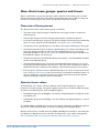
Introduction
Allied Telesis routers and managed layer 3 switches use IGMP—Internet Group Management
Protocol—to track which multicast groups their clients belong to. This enables them to send
the correct multimedia streams to the correct destination.
This How To Note describes basic and advanced IGMP configuration, in the following major
sections:
z
an overview of IGMP and definitions of some of the IGMP terminology
z
examples and discussion of the most common IGMP functionality—IGMP snooping, IGMP
Querier behaviour and selection, and IGMP proxy
z
examples and discussion of the advanced functionality available through AlliedWare’s
feature-rich IGMP implementation
z
information for debugging
z
information about the STP state of the simple three-switch ring used in most examples
Contents
Introduction .............................................................................................................................................. 1
Products and software versions this note applies to ............................................................... 3
IGMP overview .........................................................................................................................................
Queriers and Snoopers ..................................................................................................................
Messages .............................................................................................................................................
Choosing group addresses .............................................................................................................
5
5
6
7
IGMP snooping ......................................................................................................................................... 9
Example .............................................................................................................................................. 9
Explanation of IGMP snooping .................................................................................................... 11
C613-16087-00 REV C
www.alliedtelesis.com
Introduction > Contents
Multiple potential IGMP queriers ...................................................................................................... 15
Example ............................................................................................................................................ 15
Explanation of multiple potential IGMP queriers .................................................................... 17
IGMP proxy ............................................................................................................................................. 21
Example ............................................................................................................................................ 21
Explanation of IGMP proxy .......................................................................................................... 23
Query solicitation (rapid recovery from topology changes) .......................................................
How query solicitation works .....................................................................................................
Why convergence takes so long without query solicitation ................................................
Speeding up IGMP convergence in a non-looped topology .................................................
Enabling query solicitation on multiple switches in a looped topology .............................
26
26
28
33
33
IGMP filtering (controlling multicast distribution) ......................................................................... 35
Example ............................................................................................................................................ 35
Explanation of IGMP filtering (controlling multicast distribution) ...................................... 38
IGMP throttling (limiting the number of streams for each subscriber) .................................... 40
Example ............................................................................................................................................ 40
Explanation of IGMP throttling (limiting the number of streams for each subscriber) . 43
Static IGMP ............................................................................................................................................. 48
Example ............................................................................................................................................ 48
Explanation of Static IGMP .......................................................................................................... 51
How clients leave groups: queries and timers ................................................................................
Overview of leave process ...........................................................................................................
Querier timer values .....................................................................................................................
Snooper timer values ....................................................................................................................
Comparing the Querier and Snooper timers ..........................................................................
Consequences for high-loss and high-lag networks ...............................................................
58
58
58
59
60
60
IGMP fast leave ....................................................................................................................................... 61
Example ............................................................................................................................................ 61
Explanation of IGMP fast leave .................................................................................................... 63
Configurable IGMP timers and counters .........................................................................................
Timer and counter relationships ................................................................................................
Software versions ...........................................................................................................................
Initial configuration ........................................................................................................................
Default values ..................................................................................................................................
Last Member Query Count and Last Member Query Interval ...........................................
Robustness Variable .......................................................................................................................
Default Query Interval .................................................................................................................
Query Response Interval .............................................................................................................
Default Timeout Interval ..............................................................................................................
69
69
70
70
72
72
75
76
77
78
Example of bad choices for timer values .........................................................................................
Example ............................................................................................................................................
Problem 1: Last Member Query Interval too short ..............................................................
Problem 2: Query Response Interval short .............................................................................
Problem 3: Default Timeout Interval too short .....................................................................
83
83
84
84
84
Page 2 | AlliedWare™ OS How To Note: IGMP
Introduction > Products and software versions this note applies to
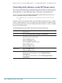
Stopping snoopers from snooping non-IGMP messages ..............................................................
Example ............................................................................................................................................
Preventing an All Groups entry for a port ...............................................................................
Controlling which addresses create All Groups entries .......................................................
86
86
90
95
Statically specifying that a port is a router port ........................................................................... 101
Example .......................................................................................................................................... 101
IGMP debugging ................................................................................................................................... 103
Example .......................................................................................................................................... 103
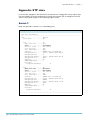
Appendix: STP state ............................................................................................................................
Switch 1 ........................................................................................................................
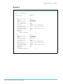
Switch 2 ..........................................................................................................................................
Switch 3 ..........................................................................................................................................
Products and software versions this note applies to
IGMP is available on all the following Allied Telesis routers and managed layer 3 switches:
z
AR400 series routers
z
AR700 series routers
z
AT-8600 series switches
z
AT-8700XL series switches
z
Rapier and Rapier i series switches
z
AT-8800 series switches
z
AT-9800 series switches
z
SwitchBlade 4000 series switches
z
AT-8948 switches
z
AT-9900 series switches
z
AT-9900s series switches
z
x900 series switches
Page 3 | AlliedWare™ OS How To Note: IGMP
108
108
109
110
Introduction > Products and software versions this note applies to
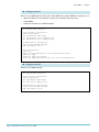
The following table shows the software versions and products each feature is available on.
IGMP feature
Software versions
Products
Snooping
All
All except AR410, AR410S, AR725 and
AR745
Multiple potential queriers
All
All
Proxy
AT-8948, x900-48: 2.8.1 and later All except AT-9800 and SwitchBlade
Other products: all versions
Filtering
2.7.5 and later
All that support this version
2.8.1 and later
All that support this version
Throttling
2.7.5 and later
All that support this version
Static IGMP
All
All switches
Configurable counters and timers
All
All
Query Solicitation
281-03 and 2.9.1 and later
All switches that support this version
Fast Leave
2.7.5 and later
All that support this version and snooping
Controlling which addresses create
All Groups entries
All
All that support snooping
Preventing All Groups entries
2.7.1 and later
All that support this version and snooping
Statically specifying router ports
281-04 and 291-04 and later
All that support this version and snooping
Filtering different message types
Snooping sub-features:
For most examples in this How To Note, we used:
z
one AT-8948 switch, with Software Version 2.7.6
z
two Rapier 24i switches, with Software Version 2.7.6
z
one PC running VLC media player as the multicast server (see www.videolan.org)
z
client PCs
Page 4 | AlliedWare™ OS How To Note: IGMP
IGMP overview > Queriers and Snoopers
IGMP overview
Clients in an IP subnetwork use IGMP to indicate
that they are interested in receiving a multicast.
IGMP then ensures that routers and switches
forward multicast packets out the appropriate
ports to the interested clients.
IGMP terms:
IGMP is very flexible, as the examples in this
How To Note show, but the basic operation is
simple. When a client wants to start receiving a
multicast—which is also called joining a multicast
group—the client sends an IGMP Membership
Report message. When a router or switch is
running IGMP and receives a Report message, it
starts forwarding traffic for the relevant multicast
group to the client.
Group
IGMP periodically polls clients by sending
General Query messages, to check that the
clients still belong to their multicast groups.
To leave a group, a client sends an IGMP Leave
message to indicate that it no longer needs to
receive the group traffic.
Note that IGMP does not exchange multicast
routing information between subnets. The
multicast routing protocols PIM and DVMRP do
this.
Queriers and Snoopers
It is neither necessary nor desirable for every
router or switch in an IP subnetwork to
coordinate multicast traffic flows. Instead, a single
router or switch does this and is called the
Querier or the Designated Router. The Querier
generates Query messages to check group
membership, and processes Membership Reports
and Leave messages.
However, other routers and switches in the
network need to know whether to send
multicasts out each of their ports. They find out
this information by becoming Snoopers. Each
Snooper checks IGMP messages before
forwarding them to and from the Querier, and
uses the information in the messages to
determine which ports to send multicasts out of.
Page 5 | AlliedWare™ OS How To Note: IGMP
Multicast or Multicast stream
A flow of information—usually video or
audio—that can go from one source to
many destination clients.
A multicast stream that clients can join.
Groups have IP addresses in the
224.0.0.0/4 network.
Group member
A client that belongs to a particular
multicast group.
IGMP Querier or Designated Router
A device in a subnetwork that is the
coordinator for all multicast streams
and IGMP membership information.
Each subnetwork has only one Querier
(see "Multiple potential IGMP
queriers" on page 15). The Querier
generates Membership Query messages
to check which clients are group
members, and processes Membership
Reports and Leave messages.
IGMP Snooper
A device that spies on IGMP messages
to create flow efficiencies by ensuring
that multicast data streams are only sent
to interested ports. A Snooper can
decide on the best path to send
multicast packets at Layer 2 but it
cannot alter those packets or generate
its own IGMP messages.
IGMP Proxy
A device that passes membership
reports upstream and multicast streams
and queries downstream. The proxy
acts on behalf of clients and servers by
altering packets.
IGMP overview > Messages
The key differences between a network’s Querier and its Snoopers are:
z
The Querier generates Query messages to find out which ports need to transmit each
multicast stream. The Snoopers also use Query messages to find this out, but they use the
Querier’s messages—Snoopers cannot create Query messages themselves.
z
The Querier has IGMP enabled as part of its IP configuration. Snoopers do not require any
configuration because snooping is enabled by default on Allied Telesis routers and managed
layer 3 switches.
z
Querying is a layer 3 feature—the Querier looks into the IP headers of packets to
determine whether to forward them. IGMP snooping is a layer 2 feature. It does not
require an IP configuration.
Messages
The following table describes the different IGMP messages in more detail.
IGMP message types:
Membership Report
A client sends this when it wants to receive a multicast group. The Membership Report is
essentially a message that declares an interest in listening to a specified group.
Leave
A client sends this when it wants to leave a group.
General Query
The Querier sends this to all clients—whether or not the Querier is currently sending multicasts
to the client—to find out which groups they are listening to. Responses to General Queries ensure
that the Querier’s group membership information stays up to date.
The group address field for General Queries is set to 0.0.0.0. They are sent to a destination
address of 224.0.0.1, and by default Allied Telesis routers and switches send them every 125
seconds.
Specific Query
The Querier sends this to a group address, to check whether clients are still listening to that group.
The Querier sends a Specific Query after a client sends a Leave message for that group. Specific
Queries enable the Querier to confirm when all downstream clients have left a group, so that the
Querier can stop sending the multicast stream.
Membership Query
This is a general term for both Specific and General Queries.
Query Solicit
Switches send this when STP or EPSR detects a topology change. The Querier responds by sending
a General Query immediately instead of waiting until groups time out. This remaps IGMP to the
new topology as quickly as possible.
Page 6 | AlliedWare™ OS How To Note: IGMP
IGMP overview > Choosing group addresses
Choosing group addresses
This section describes things you need to be aware of when choosing addresses for your
multicast groups.
Reserved IP
addresses
IP addresses in the range 224.0.0.0-239.255.255.255 are multicast addresses, but many
addresses in this range are reserved. Therefore, before choosing a multicast address, you
should check its status in the “Internet Multicast Addresses” document at the IANA website
at www.iana.org/assignments/multicast-addresses.
IPs using the
same MAC
Another complication is that multicasting is designed to use each packet’s group IP address to
determine a multicast MAC address to send the packet to. However, multicasting does not
have a 1:1 mapping of IP address to MAC address—instead each multicast MAC address
corresponds to 32 multicast IP addresses. This means that different multicast IP addresses
use the same MAC address.
The MAC address only uses the last 23 bits of the IP address; it ignores the IP’s first octet and
the first bit of the second octet. Note that all IP multicast MAC addresses start with
01-00-5E.
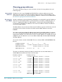
You need to avoid using multiple IP addresses that have the same MAC address. In practice,
this means that if you use x.0.y.z, then do not use x.128.y.z (or vice versa), where x is
anything from 224-239, and y and z are the same in each IP address. For example, if y=6 and
z=200 then these IP addresses use the same MAC: 224.0.6.200, 224.128.6.200, 225.0.6.200,
225.128.6.200, etc.
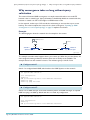
To see this in detail, consider 224.0.6.200. This has a multicast MAC of 01-00-5E-00-06-C8,
like this:
IP address, decimal:
224.
IP address, binary:
11100000 00000000 00000110 11001000
MAC address, binary:
MAC address, hex:
0.
6.
200
0000000 00000110 11001000
01-00-5E -00
-06
-C8
Therefore, the following multicast IP addresses will all have the same MAC address as
224.0.6.200, because their last 23 bits are all the same:
IP address, decimal:
IP address, binary:
224.0.6.200
11100000 0 0000000 00000110 11001000
224.128.6.200
11100000 1 0000000 00000110 11001000
225.0.6.200
11100001 0 0000000 00000110 11001000
225.128.6.200
11100001 1 0000000 00000110 11001000
226.0.6.200
11100010 0 0000000 00000110 11001000
226.128.6.200
11100010 1 0000000 00000110 11001000
227.0.6.200
11100011 0 0000000 00000110 11001000
227.128.6.200
11100011 1 0000000 00000110 11001000
...
...
239.0.6.200
11101111 0 0000000 00000110 11001000
239.128.6.200
11101111 1 0000000 00000110 11001000
...
Different IPs The same MAC
Page 7 | AlliedWare™ OS How To Note: IGMP
IGMP overview > Choosing group addresses
Avoid x.0.0.y, x.0.1.y, x.128.0.y, and x.128.1.y
It is particularly important to avoid using any address in the ranges x.0.0.y, x.128.0.y, x.0.1.y,
or x.128.1.y (where x is 224-239 and y is 1-254).
This is because x.0.0.y and x.128.0.y will map to the same multicast MAC address as 224.0.0.y.
Similarly, x.0.1.y and x.128.1.y will map to the same multicast MAC address as 224.0.1.y. Most
addresses in the ranges 224.0.0.y and 224.0.1.y are reserved for contacting all routers, or for
routing protocol messages, so they are always flooded out all ports in the relevant VLAN.
Therefore, all addresses in the ranges x.0.0.y, x.128.0.y, x.0.1.y, or x.128.1.y are flooded out
every port in the relevant VLAN. Using these addresses can significantly increase multicast
traffic in your network.
If you are debugging a situation where it seems that certain multicast groups are forwarded
when you think they shouldn’t be, check whether the choice of group addresses has violated
any of the recommendations above.
Page 8 | AlliedWare™ OS How To Note: IGMP
IGMP snooping > Example
IGMP snooping
In this example, we discuss IGMP snooping, the key to efficient multicast traffic flow in a
layer 2 network. IGMP snooping is enabled by default on switch ports in Allied Telesis
managed layer 3 switches and routers—it does not require any configuration.
In a single-switch network, IGMP snooping makes multicasting happen with no configuration
at all. All you need to do is connect your server and clients to the switch.
In a multi-switch network, at least one switch must also have an IGMP configuration. This
switch is called the IGMP Querier and coordinates the flow of multicast information through
the network. The following example describes a multi-switch configuration, so as well as
discussing the effect of IGMP snooping, it outlines the actions that the Querier takes.
"Multiple potential IGMP queriers" on page 15 discusses the role of the Querier in greater
detail.
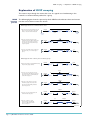
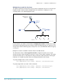
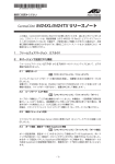
Example
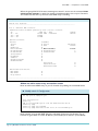
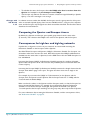
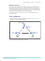
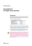
This example has a 3-switch loop, as shown in the following figure. One of the switches is
running IGMP and the other two switches are running IGMP snooping.
Multicast Server
port 1
port 50
(blocked by STP)
Switch 2:
Snooper
Rapier 24i
port 26
port 25
AT-8948
Switch 1:
Querier
port 49
port 26
Rapier 24i
port 25
port 2
port 3
Client 1
Client 2
Switch 3:
Snooper
igmp-snooper.eps
Page 9 | AlliedWare™ OS How To Note: IGMP
IGMP snooping > Example
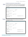
X Configure switch 1
Switch 1 is configured with IGMP, which makes it the IGMP Querier in this network. It is best
practice to make the Querier the closest switch to the multicast source, and in this example
switch 1 is closest. For more information about queriers see "Multiple potential IGMP
queriers" on page 15.
set system name="Switch 1"
# VLAN general configuration
create vlan=vlan100 vid=100
add vlan=100 port=1-52
# IP configuration
enable ip
add ip int=vlan100 ip=172.31.0.254 mask=255.255.255.0
enable ip igmp
enable ip igmp int=vlan100
# STP general configuration
enable stp=default
set stp=default mode=rapid
set stp=default port=1 edgeport=yes
X Configure switch 2
Switch 2 is an IGMP Snooper. It forwards multicast packets and IGMP messages as required.
IGMP snooping is enabled by default and does not need any configuration.
set system name="Switch 2"
# VLAN general configuration
create vlan=vlan100 vid=100
add vlan=100 port=1-26
# STP general configuration
enable stp=default
set stp=default mode=rapid
set stp port=2 edgeport=yes
X Configure switch 3
Switch 3 is also an IGMP Snooper. It forwards multicast packets and IGMP messages as
required. IGMP snooping is enabled by default and does not need any configuration.
set system name="Switch 3"
# VLAN general configuration
create vlan=vlan100 vid=100
add vlan=100 port=1-26
# STP general configuration
enable stp=default
set stp=default mode=rapid
set stp port=3 edgeport=yes
Page 10 | AlliedWare™ OS How To Note: IGMP
IGMP snooping > Explanation of IGMP snooping
Explanation of IGMP snooping
This section steps through the events that occur in a typical use of multicasting in this
network: to stream multicast packets for a group.
IGMP
learning
process
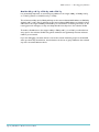
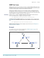
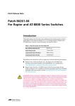
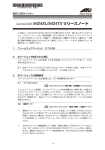
The following figure shows the process by which IGMP tracks multicast clients and ensures
that the correct clients receive the stream.
What happens before a multicast client exists:
1. Querier starts receiving multicast stream
from server. Querier has no interested
clients so doesn’t forward multicast.
Multicast
49
26
3
Querier
Blocked
by STP
Snooper 1
Snooper 2
Pontential
client
Multicast
server
GQ
2. Querier sends General Query (GQ)
to find out if any would-be clients exist.
Snooper 1 receives Query on port 26,
snoops Query, and creates All Groups
entry for port 26.
3. Snooper 1 forwards Query out all ports.
No clients exist, so no clients reply to
Query.
Multicast
49
26
Querier
Snooper 1
3
Multicast
49
GQ
26
GQ
3
Snooper 1
Querier
What happens when a client joins a multicast group:
4. Client joins group by sending Membership
Report to the group address.
Multicast
49
26
Querier
Snooper 1
Report
3
Client
Report
5. Snooper 1 receives Report on port 3,
snoops Report, and adds a group entry
for port 3. Snooper 1 forwards Report
out its All Groups port.
Multicast
49
26
Querier
Snooper 1
3
Multicast
6. Querier receives Report on port 49
and adds a group entry for port 49.
Querier starts forwarding multicast
stream out port 49.
Multicast
49
26
Querier
Snooper 1
3
Multicast
7. Snooper 1 receives multicast stream
and forwards it out port 3.
Multicast
49
26
Querier
Snooper 1
GQ
8. Querier continues to send
General Queries periodically.
These keep All Groups entries
alive on Snoopers.
Multicast
Multicast
3
Multicast
49
26
Querier
Snooper 1
Multicast
3
igmp-join.eps
Page 11 | AlliedWare™ OS How To Note: IGMP
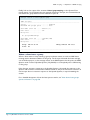
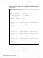
IGMP snooping > Explanation of IGMP snooping
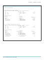
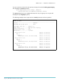
Using Show command output to investigate IGMP state
No group
members
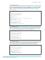
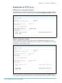
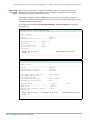
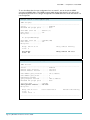
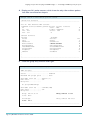
In the first stage of the figure above, the multicast server is turned on and is streaming group
224.12.13.14 to the Querier, switch 1. Switch 1 knows about the group, but has nobody
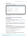
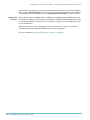
interested in receiving it. You can see this by using the command show igmpsnooping on
switch 1. The output of this command shows that switch 1 has an entry for the group, but no
associated ports.
Manager Switch 1> show igmpsnooping
IGMP Snooping
-----------------------------------------------------------------------Status ........................... Enabled
Disabled All-groups ports ........ None
Vlan Name (vlan id) ..... default (1)
Fast Leave .............. Off
Group List ..............
No group memberships.
Vlan Name (vlan id) ..... vlan100 (100)
Fast Leave .............. Off
Group List ..............
Group. 224.12.13.14
Ports None
Entry timeout 136 secs
------------------------------------------------------------------------
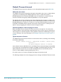
Client joins
the group
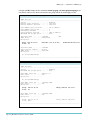
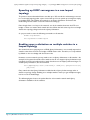
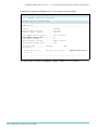
When a client joins the group, the Group List changes for the Snooper that the client is
attached to, and for the Querier. First, look at the output of the command show
igmpsnooping on the Snooper.
Manager Switch 3> show igmpsnooping
IGMP Snooping
-----------------------------------------------------------------------Status ........................... Enabled
Disabled All-groups ports ........ None
Vlan Name (vlan id) ..... default (1)
Fast Leave .............. Off
Group List ..............
No group memberships.
Vlan Name (vlan id) ..... vlan100 (100)
Fast Leave .............. Off
Group List ..............
Group. 224.12.13.14
Ports 3
Entry timeout 257 secs
All Groups
Ports 26
Entry timeout 235 secs
------------------------------------------------------------------------
Page 12 | AlliedWare™ OS How To Note: IGMP
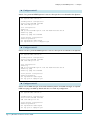
IGMP snooping > Explanation of IGMP snooping
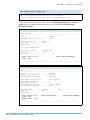
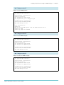
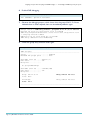
This output now shows two entries, one for each of the following:
z
group 224.12.13.14 and port 3, which shows that the client is attached to the Snooper
through port 3 and is listening to group 224.12.13.14. The Snooper created this entry at
stage 5 in the process ("IGMP learning process" on page 11). This entry means that the
Snooper forwards packets from 224.12.13.14 out port 3.
z
All Groups and port 26, which shows that the Snooper is connected to the Querier
through port 26. The Snooper created this entry at stage 2 in the process. This entry
means that the Snooper forwards all IGMP Reports and Leave messages out port 26.
The All Groups entry means that the Snooper forwards the Report from the client out port
26 to the Querier, switch 1. The Querier receives the Report on port 49.
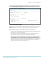
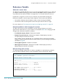
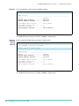
Next, look at the output of the command show ip igmp on the Querier.
Manager Switch 1> show ip igmp
IGMP Protocol
-----------------------------------------------------------------------Status ........................... Enabled
Default Query Interval ........... 125 secs
Default Timeout Interval ......... 260 secs
Last Member Query Interval .......
Last Member Query Count ..........
Robustness Variable ..............
Query Response Interval ..........
Disabled All-groups ports ........
Interface Name .......... vlan100
Group List ..............
Group. 224.12.13.14
Ports 49
10 (1/10secs)
2
2
100 (1/10secs)
None
(DR)
Last Adv. 172.31.0.223
Refresh time 256 secs
------------------------------------------------------------------------
The output above shows an entry for group 224.12.13.14 and port 49. This entry shows that
the Querier knows about a client for 224.12.13.14 which it reaches by forwarding the
multicast out port 49. The Querier created this entry at stage 6 in the process.
Page 13 | AlliedWare™ OS How To Note: IGMP
IGMP snooping > Explanation of IGMP snooping
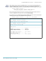
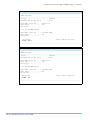
Finally, look at the output of the command show igmpsnooping on the Querier. Even
though switch 1 is the Querier for this network instead of a Snooper, this command shows
that a client for group 224.12.13.14 is reached out port 49.
Manager Switch 1> show igmpsnooping
IGMP Snooping
-----------------------------------------------------------------------Status ........................... Enabled
Disabled All-groups ports ........ None
Vlan Name (vlan id) ..... default (1)
Fast Leave .............. Off
Group List ..............
No group memberships.
Vlan Name (vlan id) ..... vlan100 (100)
Fast Leave .............. Off
Group List ..............
Group. 224.12.13.14
Ports 49
Entry timeout 247 secs
------------------------------------------------------------------------
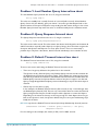
When a client leaves a group
When a client wants to stop receiving a group’s multicast stream, it sends an IGMP Leave
message with a destination address of the group. The Snooper forwards the Leave message
out its All Groups port, so the message arrives at the IGMP Querier. At this point, the IGMP
Querier sends a series of Specific Queries (2 by default) to see if anybody else is still listening
to this group.
If the Snooper receives a response to the Specific Queries, it forwards the response to the
Querier and continues to forward the multicast stream to the ports that want to receive it. If
the Snooper does not receive a response to the Specific Queries, it stops forwarding the
stream.
For a detailed description of how the leave process works, see "How clients leave groups:
queries and timers" on page 58.
Page 14 | AlliedWare™ OS How To Note: IGMP
Multiple potential IGMP queriers > Example
Multiple potential IGMP queriers
To find out more about IGMP, we next investigate what happens when more than one router
or switch has an IGMP configuration.
RFC 2236, Internet Group Management Protocol, Version 2, says that each Layer 2 network
should have only one IGMP Querier. You may configure IGMP on more than router or
switch, perhaps for redundancy, but the routers and switches have a pseudo election and the
device with the lower IP becomes the operating IGMP Querier. This example describes a
network with two potential Queriers.
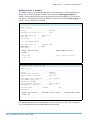
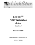
Example
The network for this example uses the same loop as for "IGMP snooping" on page 9 and is
shown in the following figure.
Multicast Server
port 1
port 50
(blocked by STP)
Switch 2:
Elected Querier
Rapier 24i
port 26
port 25
AT-8948
Switch 1:
Potential Querier
port 49
port 26
Rapier 24i
port 25
port 2
port 3
Client 1
Client 2
Switch 3:
Snooper
igmp-querier.eps
Both switch 1 and switch 2 are configured with IGMP, making both of them potential
Queriers. Switch 3, by default configuration, is an IGMP Snooper.
Page 15 | AlliedWare™ OS How To Note: IGMP
Multiple potential IGMP queriers > Example
X Configure switch 1
Switch 1 is a potential IGMP Querier. It acts as a Snooper if it is not elected as the Querier.
set system name="Switch 1"
# VLAN general configuration
create vlan=vlan100 vid=100
add vlan=100 port=1-52
# IP configuration
enable ip
add ip int=vlan100 ip=172.31.0.254 mask=255.255.255.0
enable ip igmp
enable ip igmp int=vlan100
# STP general configuration
enable stp=default
set stp=default mode=rapid
set stp=default port=1 edgeport=yes
X Configure switch 2
Switch 2 is also a potential IGMP Querier. It acts as a Snooper if not elected as the Querier.
set system name="Switch 2"
# VLAN general configuration
create vlan=vlan100 vid=100
add vlan=100 port=1-26
# IP configuration
enable ip
add ip int=vlan100 ip=172.31.0.253 mask=255.255.255.0
enable ip igmp
enable ip igmp int=vlan100
# STP general configuration
enable stp=default
set stp=default mode=rapid
set stp port=2 edgeport=yes
X Configure switch 3
Switch 3 is an IGMP Snooper. It forwards multicast packets and IGMP messages as required.
IGMP snooping is enabled by default and does not need any configuration.
set system name="Switch 3"
# VLAN general configuration
create vlan=vlan100 vid=100
add vlan=100 port=1-26
# STP general configuration
enable stp=default
set stp=default mode=rapid
set stp port=3 edgeport=yes
Page 16 | AlliedWare™ OS How To Note: IGMP
Multiple potential IGMP queriers > Explanation of Multiple potential IGMP queriers
Explanation of Multiple potential IGMP queriers
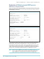
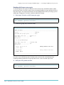
When there are no group members
Switch 1 and switch 2 are both possible Queriers, and an election determines which switch
becomes the actual Querier. We can see the results of the election by using the command
show ip igmp on each switch.
Manager Switch 1> show ip igmp
IGMP Protocol
-----------------------------------------------------------------------Status ........................... Enabled
Default Query Interval ........... 125 secs
Default Timeout Interval ......... 260 secs
Last Member Query Interval .......
Last Member Query Count ..........
Robustness Variable ..............
Query Response Interval ..........
Disabled All-groups ports ........
10 (1/10secs)
2
2
100 (1/10secs)
None
Interface Name .......... vlan100
Other Querier timeout ... 209 secs
Group List ..............
------------------------------------------------------------------------
Manager Switch 2> show ip igmp
IGMP Protocol
-----------------------------------------------------------------------Status ........................... Enabled
Default Query Interval ........... 125 secs
Default Timeout Interval ......... 260 secs
Last Member Query Interval .......
Last Member Query Count ..........
Robustness Variable ..............
Query Response Interval ..........
Disabled All-groups ports ........
Interface Name .......... vlan100
IGMP Proxy .............. Off
Group List ..............
10 (1/10secs)
2
2
100 (1/10secs)
None
(DR)
------------------------------------------------------------------------
In the output from switch 2 above, switch 2 reports that it has become the Querier by
displaying (DR)—which stands for Designated Router—next to the interface name.
In the output from switch 1 above, switch 1 has an entry for Other Querier timeout, which
indicates that it is aware that another device is the IGMP Querier. If the timer expires,
switch 1 will decide that the other Querier no longer exists, and will become the Querier
itself. The timer is refreshed by a Membership Query or an IGMP Querier election.
Note:
Switch 2 shows an IGMP Proxy entry, which is set to Off (see "IGMP proxy" on
page 21). Switch 1 does not show a Proxy entry because the AT-8948 did not
support IGMP Proxy on Software Version 2.7.6 which this example used.
Page 17 | AlliedWare™ OS How To Note: IGMP
Multiple potential IGMP queriers > Explanation of Multiple potential IGMP queriers
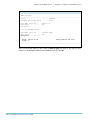
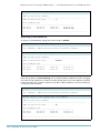
When a client joins a group
Now imagine that Client 1 sends a Membership Report to switch 2 for the group
224.12.13.14. If we check the group membership for switch 2 by using the command show
igmpsnooping, we see a group entry for 224.12.13.14.
Manager Switch 2> show igmpsnooping
IGMP Snooping
-----------------------------------------------------------------------Status ........................... Enabled
Disabled All-groups ports ........ None
Vlan Name (vlan id) ..... default (1)
Fast Leave .............. Off
Group List ..............
No group memberships.
Vlan Name (vlan id) ..... vlan100 (100)
Fast Leave .............. Off
Group List ..............
Group. 224.12.13.14
Ports 2
Entry timeout 225 secs
------------------------------------------------------------------------
If we check the group membership for switches 1 and 3, we see no entries for 224.12.13.14,
but see an All Groups entry on each switch. The All Groups entry points to the Querier,
switch 2. The output for switch 1, for example, shows port 49 as the All Groups port,
indicating that switch 1 reaches the Querier via port 49.
Manager Switch 1> show igmpsnooping
IGMP Snooping
-----------------------------------------------------------------------Status ........................... Enabled
Disabled All-groups ports ........ None
Vlan Name (vlan id) ..... default (1)
Fast Leave .............. Off
Group List ..............
No group memberships.
Vlan Name (vlan id) ..... vlan100 (100)
Fast Leave .............. Off
Group List ..............
Group. 224.12.13.14
Ports None
Entry timeout 25 secs
All Groups
Ports 49
Entry timeout 177 secs
------------------------------------------------------------------------
Note:
An All Groups port does not necessarily indicate that an IGMP Querier can be found
via that port—it could be a router instead. See "Controlling which addresses create
All Groups entries" on page 95 for more information.
Page 18 | AlliedWare™ OS How To Note: IGMP
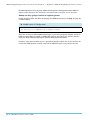
Multiple potential IGMP queriers > Explanation of Multiple potential IGMP queriers
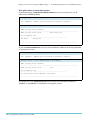
To see the difference between a switch acting as a Snooper and a switch acting as a Querier,
compare the IGMP snooping table for switch 1 (above) with its IGMP table (below). They
seem to contradict each other. The IGMP snooping table tells us that switch 1 is aware that it
is receiving the group 224.12.13.14 and will send all groups (including this one) out port 49
towards the IGMP Querier, switch 2. However, the IGMP table shows that IGMP has not
registered any interested clients—the group list is empty.
Manager Switch 1> show ip igmp
IGMP Protocol
-----------------------------------------------------------------------Status ........................... Enabled
Default Query Interval ........... 125 secs
Default Timeout Interval ......... 260 secs
Last Member Query Interval .......
Last Member Query Count ..........
Robustness Variable ..............
Query Response Interval ..........
Disabled All-groups ports ........
10 (1/10secs)
2
2
100 (1/10secs)
None
Interface Name .......... vlan100
Other Querier timeout ... 214 secs
Group List ..............
------------------------------------------------------------------------
This disparity between the IGMP snooping table and the IGMP table simply shows that
switch 1 is acting as a Snooper because it did not become the Querier. The IGMP table on
switch 1 has no entries because no Report message has been seen on switch 1. The disparity
does not appear in the output for switch 2, because switch 2 is the Querier. The IGMP and
IGMP snooping tables show the same group entries on switch 2.
Manager Switch 2> show ip igmp
IGMP Protocol
-----------------------------------------------------------------------Status ........................... Enabled
Default Query Interval ........... 125 secs
Default Timeout Interval ......... 260 secs
Last Member Query Interval .......
Last Member Query Count ..........
Robustness Variable ..............
Query Response Interval ..........
Disabled All-groups ports ........
Interface Name .......... vlan100
IGMP Proxy .............. Off
Group List ..............
10 (1/10secs)
2
2
100 (1/10secs)
None
(DR)
Group. 224.12.13.14
Last Adv. 172.31.0.222
Refresh time 228 secs
Ports 2
------------------------------------------------------------------------
Page 19 | AlliedWare™ OS How To Note: IGMP
Multiple potential IGMP queriers > Explanation of Multiple potential IGMP queriers
Manager Switch 2> show igmpsnooping
IGMP Snooping
-----------------------------------------------------------------------Status ........................... Enabled
Disabled All-groups ports ........ None
Vlan Name (vlan id) ..... default (1)
Fast Leave .............. Off
Group List ..............
No group memberships.
Vlan Name (vlan id) ..... vlan100 (100)
Fast Leave .............. Off
Group List ..............
Group. 224.12.13.14
Ports 2
Entry timeout 225 secs
------------------------------------------------------------------------
Also, note that (DR) appears in the output of show ip igmp on switch 2. This tells you that
switch 2 is the Designated Router (the IGMP Querier) for vlan100.
Page 20 | AlliedWare™ OS How To Note: IGMP
IGMP proxy > Example
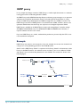
IGMP proxy
In very simple tree-design networks, IGMP Proxy is a useful simple alternative to a multicast
routing protocol for multicasting between VLANs.
An IGMP Proxy sends IGMP Membership Report and Leave group messages to an upstream
subnetwork on behalf of downstream devices, and sends Queries downstream. In other
words, an IGMP Proxy effectively ferries IGMP messages from one VLAN to another. The
IGMP Proxy looks like an IGMP Querier to the downstream VLAN, and like a client to the
upstream VLAN. Note that the Proxy can only have one configured upstream VLAN.
IGMP Proxy is available on all Allied Telesis routers and managed layer 3 switches except
AT-9800 and SwitchBlade series. For AT-8948, AT-9900 and x900-48 series switches, it
requires software version 2.8.1 or later.
If you use IGMP Proxy on a switch, multicast data packets are processed by the CPU so are
not forwarded at wirespeed.
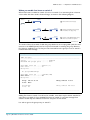
Example
IGMP Proxy only works in tree networks, so for this example we convert the network from
a loop into a tree by disabling port 50 on the AT-8948 switch.
Switch 3 is the IGMP Proxy. Switch 1 is upstream of the Proxy. Switch 2 is downstream of the
Proxy on vlan100. Therefore, the multicast server and client 1 are now in different VLANs
and switch 3 sits on the boundary between the two VLANs. This network is shown in the
following figure.
Multicast Server
port 1
vlan200
AT-8948
Switch 1:
Querier
port 49
upstream
vlan200
Switch 2:
Snooper
port 26
Rapier 24i
port 25
downstream
vlan100
port 25
Rapier 24i
Switch 3:
Proxy
port 2
Client 1
igmp-proxy.eps
Page 21 | AlliedWare™ OS How To Note: IGMP
IGMP proxy > Example
X Configure switch 1
Switch 1—the closest switch to the multicast source—is an IGMP Querier.
set system name="Switch 1"
# Switching configuration
disable switch port=50 link=disable
# VLAN general configuration
create vlan=vlan200 vid=200
add vlan=200 port=1-49
# IP configuration
enable ip
add ip int=vlan200 ip=172.31.1.254 mask=255.255.255.0
enable ip igmp
enable ip igmp int=vlan200
X Configure switch 2
Switch 2 is an IGMP Snooper. IGMP snooping is enabled by default and does not need any
configuration.
set system name="Switch 2"
# VLAN general configuration
create vlan=vlan100 vid=100
add vlan=100 port=1-26
# IP configuration
enable ip
add ip int=vlan100 ip=172.31.0.252 mask=255.255.255.0
X Configure switch 3
Switch 3 is an IGMP Proxy.
set system name="Switch 3"
# VLAN general configuration
create vlan=vlan100 vid=100
add vlan=100 port=1-25
create vlan=vlan200 vid=200
add vlan=200 port=26
# IP configuration
enable ip
add ip int=vlan100 ip=172.31.0.253 mask=255.255.255.0
igmpproxy=downstream
add ip int=vlan200 ip=172.31.1.253 mask=255.255.255.0 igmpproxy=upstream
enable ip igmp
enable ip igmp int=vlan100
enable ip igmp int=vlan200
Page 22 | AlliedWare™ OS How To Note: IGMP
IGMP proxy > Explanation of IGMP proxy
Explanation of IGMP proxy
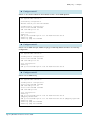
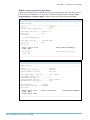
When there are no group members
The multicast server streams group 224.12.13.14 to switch 1 through port 1. IGMP snooping
detects the stream, as you can see by using the command show igmpsnooping on switch 1.
Manager Switch 1> show igmpsnooping
IGMP Snooping
-----------------------------------------------------------------------Status ........................... Enabled
Disabled All-groups ports ........ None
Vlan Name (vlan id) ..... default (1)
Group List ..............
No group memberships.
Vlan Name (vlan id) ..... vlan200 (200)
Group List ..............
Group. 224.12.13.14
Ports None
Entry timeout 122 secs
------------------------------------------------------------------------
When a client joins a group
Client 1 (attached to switch 2, the Snooper) sends an IGMP Membership Report for the
group 224.12.13.14. Switch 2 forwards that report message in an unmodified state out its All
Groups ports—in this case port 25.
Manager Switch 2> show igmpsnooping
IGMP Snooping
-----------------------------------------------------------------------Status ........................... Enabled
Disabled All-groups ports ........ None
Vlan Name (vlan id) ..... default (1)
Fast Leave .............. Off
Group List ..............
No group memberships.
Vlan Name (vlan id) ..... vlan100 (100)
Fast Leave .............. Off
Group List ..............
Group. 224.12.13.14
Ports 2
Entry timeout 256 secs
All Groups
Ports 25
Entry timeout 145 secs
------------------------------------------------------------------------
Switch 3—the Proxy—receives the report on its downstream interface, vlan100. Switch 3
then creates a new report with itself as the sender. It sends this report upstream to switch 1
Page 23 | AlliedWare™ OS How To Note: IGMP
IGMP proxy > Explanation of IGMP proxy
through vlan200. Output of the commands show ip igmp and show igmpsnooping show
that switch 3 knows of a client interested in the group 224.12.13.14 through port 25.
Manager Switch 3> show ip igmp
IGMP Protocol
-----------------------------------------------------------------------Status ........................... Enabled
Default Query Interval ........... 125 secs
Default Timeout Interval ......... 260 secs
Last Member Query Interval .......
Last Member Query Count ..........
Robustness Variable ..............
Query Response Interval ..........
Disabled All-groups ports ........
10 (1/10secs)
2
2
100 (1/10secs)
None
Interface Name .......... vlan100
IGMP Proxy .............. Downstream
Group List ..............
Group. 224.12.13.14
Ports 25
(DR)
Last Adv. 172.31.0.222
Refresh time 243 secs
Interface Name .......... vlan200
Other Querier timeout ... 0 secs
IGMP Proxy .............. Upstream
Group List ..............
No group memberships.
------------------------------------------------------------------------
Manager Switch 3> show igmpsnooping
IGMP Snooping
-----------------------------------------------------------------------Status ........................... Enabled
Disabled All-groups ports ........ None
Vlan Name (vlan id) ..... default (1)
Fast Leave .............. Off
Group List ..............
No group memberships.
Vlan Name (vlan id) ..... vlan100 (100)
Fast Leave .............. Off
Group List ..............
Group. 224.12.13.14
Ports 25
Entry timeout 239 secs
Vlan Name (vlan id) ..... vlan200 (200)
Fast Leave .............. Off
Group List ..............
Group. 224.12.13.14
Ports None
Entry timeout 260 secs
------------------------------------------------------------------------
Page 24 | AlliedWare™ OS How To Note: IGMP
IGMP proxy > Explanation of IGMP proxy
Switch 1 receives the proxied report from switch 3. Switch 1 notes that switch 3 is interested
in the group 224.12.13.14 and sends the group multicast to switch 3 on port 49. Output of
the command show igmpsnooping shows the membership that switch 1 is aware of.
Manager Switch 1> show igmpsnooping
IGMP Snooping
-----------------------------------------------------------------------Status ........................... Enabled
Disabled All-groups ports ........ None
Vlan Name (vlan id) ..... default (1)
Group List ..............
No group memberships.
Vlan Name (vlan id) ..... vlan200 (200)
Group List ..............
Group. 224.12.13.14
Entry timeout 182 secs
Ports 49
------------------------------------------------------------------------
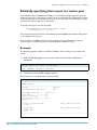
When a client leaves a group
When the client on switch 2 wants to stop receiving the group’s multicast stream, it sends an
IGMP Leave message. The switches use the above process to transfer the message to
switch 1.
Note the following points about how IGMP Proxy deals with Leave messages:
z
The Proxy sends an IGMP Leave Group message via its upstream interface only when the
last interface on the Proxy leaves the group.
z
The Proxy does not respond to IGMP Join or Leave Group messages received via its
upstream interface, but only to those received via downstream interfaces.
z
The Proxy does respond to IGMP query messages received via its upstream interface.
When the Proxy—switch 3 in this example—sends a Leave Group message upstream, the
upstream IGMP Querier—switch 1—sends a membership query. Switch 3 takes that
query and proxies it to the downstream interface, vlan100, with its own IP as the source
(172.31.0.253). This means any other interested clients on switch 2 can declare their
interest in continuing to receive the multicast stream.
Page 25 | AlliedWare™ OS How To Note: IGMP
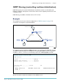
Query solicitation (rapid recovery from topology changes) > How query solicitation works
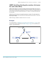
Query solicitation (rapid recovery from topology
changes)
Query Solicitation minimises loss of multicast data after a topology change. It is a built-in
feature of Allied Telesis managed layer 3 switches since software versions 281-03 and 2.9.1
when running EPSR or spanning tree (STP, RSTP, or MSTP) for loop protection.
Without Query Solicitation, when the underlying link layer topology changes, multicast data
flow can stop for up to several minutes, depending on which port goes down and how much
of the timeout period was left (see "Why convergence takes so long without query
solicitation" on page 28). Query Solicitation greatly reduces this disruption.
Query Solicitation operates without configuration in networks of Allied Telesis managed
layer 3 switches running STP, RSTP, MSTP or EPSR. You may find it helpful to manually enable
it in the following other situations:
z
loop-free networks running IGMP (see page 33)
z
networks in which not all switches support Query Solicitation (see page 33)
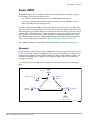
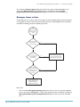
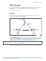
How query solicitation works
Query Solicitation monitors STP, RSTP, MSTP and EPSR messages for topology changes.
When it detects a change, it generates a special IGMP Leave message called a Query Solicit.
The switch floods the Query Solicit message to all ports in every VLAN that Query
Solicitation is enabled on. When the Querier receives the Query Solicit message, it sends out
a General Query and waits for clients to respond with Membership Reports. These Reports
update the snooping information throughout the network.
Query Solicit messages have a group address of 0.0.0.0.
Query Solicitation works by default (without you enabling it) on all VLANs on the root
bridge in an STP instance and on all data VLANs on the master node in an EPSR instance. By
default, the root bridge or master node always sends a Query Solicit message when any of
the following events occur:
z
an STP BPDU packet with the Topology Change (TC) flag arrives at the root bridge
z
an STP port on a switch goes from a Discarding to Forwarding state
z
the FDB gets flushed by EPSR
If necessary, you can make clients respond more quickly to the General Query by tuning the
IGMP timers, especially the Query Response Interval—see page 77.
Page 26 | AlliedWare™ OS How To Note: IGMP
Query solicitation (rapid recovery from topology changes) > How query solicitation works
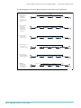
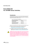
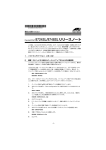
The following figure shows how Query Solicitation works when a port goes down.
Multicast
Initial state:
Port on Switch 3
is blocking.
Multicasts flow
from server to
client via Switches
1 and 4
Switch 2: STP root
Switch 1: Querier
Switch 4
Switch 3
Multicast
Multicast
1. Link to Switch 4
goes down.
Switch 3 stops
blocking and
sends topology
change (TC)
Switch 2: STP root
Switch 3
TC
2. Switch 2 receives
TC and sends
Query Solicit (QS)
Switch 2: STP root
3. Switch 1 receives
QS and sends
General Query (GQ)
QS
QS
QS
GQ
GQ
GQ
Report
Report
Switch 1: Querier
GQ
4. Host receives GQ
and responds with
Membership Report
Final state:
Multicasts flow
from server to
client via Switches
1, 2, 3, and 4
Switch 1: Querier
Multicast
Switch 2: STP root
Multicast
Multicast
Report
Report
Switch 4
Switch 3
Multicast
Multicast
igmp-qs.eps
Page 27 | AlliedWare™ OS How To Note: IGMP
Query solicitation (rapid recovery from topology changes) > Why convergence takes so long without query solicitation
Why convergence takes so long without query
solicitation
This section illustrates IGMP convergence in a simple network that does not need STP
because it has no switch loops. Query Solicitation is disabled by default in networks like this,
because no switch is an STP root bridge or an EPSR master node.
In this network, it takes up to 125 seconds for multicasting to recover after a port comes
back up. This section explains the reason for the slow convergence. "Speeding up IGMP
convergence in a non-looped topology" on page 33 explains the solution.
Example
The following figure shows the network for the example in this section.
Multicast Server
Client 1
port 24
Switch 1:
Querier
port 9
port 1
port 1
Rapier 24i
Rapier 24i
Switch 2:
Snooper
igmp-no-qs.eps
The example considers what happens when a port comes up. When the port was down, the
client stopped receiving multicasts, because there was no backup route available. The
example shows how the network recovers. The multicast group is 224.12.13.14.
X Configure switch 1
Switch 1 is configured with IGMP, which makes it the IGMP Querier in this network.
set system name="Switch 1"
# IP configuration
enable ip
add ip int=vlan1 ip=10.13.2.191 mask=255.255.255.0
enable ip igmp
enable ip igmp int=vlan1
X Configure switch 2
Switch 2 is an IGMP Snooper. It forwards multicast packets and IGMP messages as required.
IGMP snooping is enabled by default and does not need any configuration.
set system name="Switch 2"
# IP configuration
enable ip
add ip int=vlan1 ip=10.13.2.193 mask=255.255.255.0
Page 28 | AlliedWare™ OS How To Note: IGMP
Query solicitation (rapid recovery from topology changes) > Why convergence takes so long without query solicitation
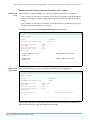
Explanation from the perspective of switch 2, the snooper
When link
is up
When the link is connected (all ports are up), the Snooper has entries for two ports:
z
port 9, which is the Snooper’s connection to the client. The Snooper sends the multicast
stream out this port, as well as sending Queries (the Snooper floods Queries out all its
ports)
z
port 1, which is the Snooper’s connection to the Querier. This is an All Groups entry, so
the Snooper forwards Reports out this port.
The output of the command show igmpsnooping shows both entries.
Manager Switch 2> show igmpsnooping
IGMP Snooping
-----------------------------------------------------------------------Status ........................... Enabled
Disabled All-groups ports ........ None
Vlan Name (vlan id) .....
Fast Leave ..............
Query Solicitation ......
Static Router Ports .....
Group List ..............
default (1)
Off
Off
None
Group. 224.12.13.14
Ports 9
Entry timeout 228 secs
All Groups
Ports 1
Entry timeout 232 secs
------------------------------------------------------------------------
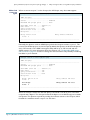
When link
goes down
When we disconnect port 1 on the Snooper, the All Groups entry disappears.
Manager Switch 2> show igmpsnooping
IGMP Snooping
-----------------------------------------------------------------------Status ........................... Enabled
Disabled All-groups ports ........ None
Vlan Name (vlan id) .....
Fast Leave ..............
Query Solicitation ......
Static Router Ports .....
Group List ..............
Group. 224.12.13.14
Ports 9
default (1)
Off
Off
None
Entry timeout 196 secs
------------------------------------------------------------------------
The Snooper still knows to send Queries and the multicast stream out port 9. However, it
does not know where to send any IGMP Report messages.
Page 29 | AlliedWare™ OS How To Note: IGMP
Query solicitation (rapid recovery from topology changes) > Why convergence takes so long without query solicitation
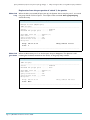
When link
comes up
again
When we reconnect port 1 on the Snooper, the All Groups entry does not reappear.
Manager Switch 2> show igmpsnooping
IGMP Snooping
-----------------------------------------------------------------------Status ........................... Enabled
Disabled All-groups ports ........ None
Vlan Name (vlan id) .....
Fast Leave ..............
Query Solicitation ......
Static Router Ports .....
Group List ..............
default (1)
Off
Off
None
Group. 224.12.13.14
Ports 9
Entry timeout 140 secs
------------------------------------------------------------------------
Eventually, the Querier sends an IGMP Query, which the Snooper receives on port 1. This
restores the All Groups port on the Snooper. By default the Querier sends General Queries
every 125 seconds, so the IGMP convergence delay will be up to 125 seconds with the
default settings. For more information about this timeout, see "Configurable IGMP timers
and counters" on page 69—but do not change the timeout without very carefully considering
the effect on your network.
Manager Switch 2> show igmpsnooping
IGMP Snooping
-----------------------------------------------------------------------Status ........................... Enabled
Disabled All-groups ports ........ None
Vlan Name (vlan id) .....
Fast Leave ..............
Query Solicitation ......
Static Router Ports .....
Group List ..............
default (1)
Off
Off
None
Group. 224.12.13.14
Ports 9
Entry timeout 107 secs
All Groups
Ports 1
Entry timeout 236 secs
------------------------------------------------------------------------
When the Snooper receives the General Query, it forwards it out all its ports. The client
responds with a Report. The Snooper forwards the Report out its All Groups port towards
the Querier. The Querier responds by sending the multicast stream to the Snooper, which
forwards the multicast stream out port 9 to the client.
Page 30 | AlliedWare™ OS How To Note: IGMP
Query solicitation (rapid recovery from topology changes) > Why convergence takes so long without query solicitation
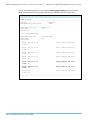
Explanation from the perspective of switch 1, the querier
When link
is up
When the link is connected (all ports are up), the Querier has an entry for port 1, so it sends
the group 224.12.13.14 out port 1. The output of the command show igmpsnooping
shows this entry.
Manager Switch 1> show igmpsnooping
Manager A> show igmpsnooping
IGMP Snooping
-----------------------------------------------------------------------Status ........................... Enabled
Disabled All-groups ports ........ None
Vlan Name (vlan id) .....
Fast Leave ..............
Query Solicitation ......
Static Router Ports .....
Group List ..............
default (1)
Off
Off
None
Group. 224.12.13.14
Ports 1
Entry timeout 18 secs
------------------------------------------------------------------------
When link
goes down
When we disconnect port 1 on the Snooper, the port disappears. The Querier is still
receiving the multicast stream from the server, so the group entry remains.
Manager Switch 1> show igmpsnooping
IGMP Snooping
-----------------------------------------------------------------------Status ........................... Enabled
Disabled All-groups ports ........ None
Vlan Name (vlan id) .....
Fast Leave ..............
Query Solicitation ......
Static Router Ports .....
Group List ..............
Group. 224.12.13.14
Ports None
default (1)
Off
Off
None
Entry timeout 255 secs
------------------------------------------------------------------------
Page 31 | AlliedWare™ OS How To Note: IGMP
Query solicitation (rapid recovery from topology changes) > Why convergence takes so long without query solicitation
When link
comes up
again
When we reconnect port 1 on the Snooper, the port does not reappear because the
Querier has not yet received a Report over it. Therefore, the Querier does not start
forwarding the multicast stream out the port.
Eventually, the Querier sends an IGMP Query out all its ports. In response it receives a
Report from the client (via the Snooper). This restores the port entry and the Querier starts
sending the multicast stream again.
The output of the commands show igmpsnooping and show ip igmp both show this
restored entry.
Manager Switch 1> show igmpsnooping
IGMP Snooping
-----------------------------------------------------------------------Status ........................... Enabled
Disabled All-groups ports ........ None
Vlan Name (vlan id) .....
Fast Leave ..............
Query Solicitation ......
Static Router Ports .....
Group List ..............
default (1)
Off
Off
None
Group. 224.12.13.14
Ports 1
Entry timeout 115 secs
------------------------------------------------------------------------
Manager Switch 1> show ip igmp
IGMP Protocol
-----------------------------------------------------------------------Status ........................... Enabled
Default Query Interval ........... 125 secs
Default Timeout Interval ......... 260 secs
Last Member Query Interval .......
Last Member Query Count ..........
Robustness Variable ..............
Query Response Interval ..........
Disabled All-groups ports ........
10 (1/10secs)
2
2
100 (1/10secs)
None
Interface Name .....................
IGMP Status ........................
IGMP Proxy .........................
General Query Reception Timeout ....
Group List .........................
vlan1
Enabled
Off
None
(DR)
Group. 224.12.13.14
Last Adv. 10.13.2.11
Refresh time 110 secs
Ports 1
------------------------------------------------------------------------
Page 32 | AlliedWare™ OS How To Note: IGMP
Query solicitation (rapid recovery from topology changes) > Speeding up IGMP convergence in a non-looped topology
Speeding up IGMP convergence in a non-looped
topology
The previous section described how it can take up to 125 seconds for multicasting to recover
in a non-looped topology after a port comes back up. You can speed up convergence simply
by enabling RSTP. This enables the network to use Query Solicitation and means that
multicasting resumes within 3 seconds of the link coming up.
Even though there is no loop in the network, one of the switches becomes the STP root
bridge—it does not matter which switch does this. When the link comes up, the root bridge
detects the topology change and sends a Query Solicitation.
So you just need to enter the following commands on all switches:
enable stp=default
set stp=default mode=rapid
Enabling query solicitation on multiple switches in a
looped topology
On networks that use spanning tree or EPSR, Query Solicitation is not normally required on
switches other than the STP root bridge or EPSR master node. Therefore, it is only enabled
by default on the root bridge and the master node.
However, in some networks you may need to turn on Query Solicitation on all switches—for
example, if the network includes other switches that do not support Query Solicitation and
therefore the STP root bridge may be a switch that does not send Query Solicit messages. To
enable Query Solicitation, use the command:
set igmpsnooping vlan={vlan-name|1..4094|all} querysolicit={on|
yes|true}
Every switch that has Query Solicitation enabled sends a Query Solicit message when it
detects a topology change. Enabling it on multiple switches means you get multiple messages,
but has no other disadvantage.
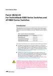
The following figure shows a the packet flow for a four-switch network with Query
Solicitation enabled on all the switches.
Page 33 | AlliedWare™ OS How To Note: IGMP
Query solicitation (rapid recovery from topology changes) > Enabling query solicitation on multiple switches in a looped topology
Multicast
Initial state:
Port on switch 3
is blocking.
Multicasts flow
from server to
client via switches
1 and 4
Switch 2: STP root
Switch 1: Querier
Multicast
1. Link to switch 4
goes down.
Switch 3 stops
blocking and
sends Topology
Change (TC) and
Query Solicit (QS).
Switch 2 forwards
QS to switch 1.
Switch 1 sends
General Query (GQ)
Multicast
Switch 1: Querier
2. Switch 2 receives TC
from switch 3.
Switch 2 sends QS.
to switch 1.
Switch 1 sends GQ
Switch 2: STP root
Switch 4
Switch 3
QS from 3
QS from 3
GQ from 1
GQ from 1
GQ from 1
TC from 3
TC from 3
Switch 1: Querier
Switch 2: STP root
GQ from 1
Switch 4
Switch 3
QS from 2
GQ from 1
3. Switch 4 receives TC
from switch 3.
Switch 4 sends QS.
towards switch 1.
Switch 1 sends GQ
Switch 1: Querier
4. Client replies to each
GQ by sending
Membership Reports
Final state:
Multicasts flow
from server to
client via Switches
1, 2, 3, and 4
Switch 3
Switch 2: STP root
GQ from 1
QS from 4
QS from 4
GQ from 1
GQ from 1
GQ from 1
Switch 1: Querier
Switch 2: STP root
GQ from 1
Switch 4
Switch 3
QS from 4
Switch 1: Querier
Multicast
GQ from 1
GQ from 1
Switch 4
Switch 3
Report
Report
Report
Report
Report
Report
Report
Report
Report
Report
Report
Report
Switch 2: STP root
Multicast
Multicast
Switch 4
Switch 3
Multicast
Multicast
igmp-qs.eps
So one topology change caused three Query Solicits, three General Queries, and three
Reports.
Page 34 | AlliedWare™ OS How To Note: IGMP
IGMP filtering (controlling multicast distribution) > Example
IGMP filtering (controlling multicast distribution)
IGMP filtering lets you control the distribution of multicast services on each switch port.
Filtering is useful for subscription services when clients must be explicitly authorised to view
a multicast stream.
IGMP Filtering is available in Software Version 2.7.5 or later.
Example
This example uses the same network configuration as "IGMP snooping" on page 9. For
convenience, the diagram is reproduced below.
Multicast Server
port 1
port 50
(blocked by STP)
Switch 2:
Snooper
Rapier 24i
AT-8948
Switch 1:
Querier
port 49
port 26
port 26
port 25
Rapier 24i
port 25
port 2
port 3
Client 1
Client 2
Switch 3:
Snooper
igmp-snooper.eps
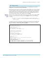
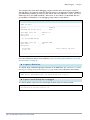
The network contains a Windows 2000 workstation that regularly sends SVRLOC messages
(an IGMP Membership Report for 224.0.1.22). This group gets added to the list of groups in
vlan100 on switch 1, as shown in the following output of the show ip igmp command.
Manager Switch 1> show ip igmp
IGMP Protocol
-----------------------------------------------------------------------Status ........................... Enabled
Default Query Interval ........... 125 secs
Default Timeout Interval ......... 260 secs
...
Interface Name .......... vlan100
Group List ..............
Group. 224.0.1.22
Ports 1
(DR)
Last Adv. 172.31.0.99
Refresh time 251 secs
------------------------------------------------------------------------
We do not need to receive this multicast, so we will filter it out.
Page 35 | AlliedWare™ OS How To Note: IGMP
IGMP filtering (controlling multicast distribution) > Example
X Configure switch 1
Switch 1—the closest switch to the multicast source—is an IGMP Querier. The filter is
configured on it, as shown in bold in the script below.
Note that the order of entries in a filter is important. When IGMP tries to match a message
to a filter, it performs a linear search of the filter to find a matching entry, starting with the
lowest-numbered entry. It stops processing the filter at the first match it finds. Therefore,
this filter has an entry with one multicast group and an action of exclude, followed by an
entry with all multicast groups and an (implicit) action of include.
Different
message
types
Also note that in software versions 2.8.1 and later, each entry filters only one type of IGMP
message. To control the type of message, use the msgtype parameter in the following
command:
add igmp filter=filter-id groupaddress={ipadd|ipadd-ipadd}
[entry=1..65535] [action={include|exclude}] [msgtype={query|
report|leave}]
In software version 2.8.1, this parameter is mandatory. Since software versions 281-01 and
2.9.1, the parameter is optional with a default of report. In this example we are filtering
Reports, so we do not need to specify the message type.
set system name="Switch 1"
# STP general configuration
enable stp=default
set stp=default mode=rapid
set stp=default port=1 edgeport=yes
# VLAN general configuration
create vlan=vlan100 vid=100
add vlan=100 port=1-52
# Switching configuration
set switch port=1 igmpfilter=1
# IP configuration
enable ip
add ip int=vlan100 ip=172.31.0.254 mask=255.255.255.0
enable ip igmp
enable ip igmp int=vlan100
create igmp filter=1
add igmp filter=1 entry=1 group=224.0.1.22 action=exclude
add igmp filter=1 entry=2 group=224.0.0.0-239.255.255.255
Page 36 | AlliedWare™ OS How To Note: IGMP
IGMP filtering (controlling multicast distribution) > Example
X Configure switch 2
Switch 2 is an IGMP Snooper. IGMP snooping is enabled by default and does not need any
configuration.
set system name="Switch 2"
# STP general configuration
enable stp=default
set stp=default mode=rapid
set stp port=2 edgeport=yes
# VLAN general configuration
create vlan=vlan100 vid=100
add vlan=100 port=1-26
X Configure switch 3
Switch 3 is also an IGMP Snooper.
set system name="Switch 3"
# STP general configuration
enable stp=default
set stp=default mode=rapid
set stp port=3 edgeport=yes
# VLAN general configuration
create vlan=vlan100 vid=100
add vlan=100 port=1-26
Page 37 | AlliedWare™ OS How To Note: IGMP
IGMP filtering (controlling multicast distribution) > Explanation of IGMP filtering (controlling multicast distribution)
Explanation of IGMP filtering (controlling multicast
distribution)
Immediately after applying the filter, we check the group entries on switch 1 by using the
command show ip igmp, and see that the switch still has an entry for the group we are
filtering out.
Manager Switch 1> show ip igmp
IGMP Protocol
-----------------------------------------------------------------------Status ........................... Enabled
Default Query Interval ........... 125 secs
Default Timeout Interval ......... 260 secs
Last Member Query Interval .......
Last Member Query Count ..........
Robustness Variable ..............
Query Response Interval ..........
Disabled All-groups ports ........
10 (1/10secs)
2
2
100 (1/10secs)
None
Interface Name .......... vlan100
Group List ..............
Group. 224.0.1.22
Ports 1
Last Adv. 172.31.0.99
(DR)
Refresh time 192 secs
------------------------------------------------------------------------
This entry is still there because the switch had previously received a report for the group.
Since applying the filter, there have not been any messages for the group, so the switch has
not yet filtered the group out. We can see this by using the command show igmp filter to
check the number of processed messages.
Manager Switch 1> show igmp filter=1
IGMP Filters
-----------------------------------------------------------------No. Entry Group Address
Action
Matches
-----------------------------------------------------------------1
1
224.0.1.22
224.0.1.22
Exclude
0
2
224.0.0.0
224.255.255.255 Include
0
Received: 0
Passed: 0
Dropped: 0
------------------------------------------------------------------------
Page 38 | AlliedWare™ OS How To Note: IGMP
IGMP filtering (controlling multicast distribution) > Explanation of IGMP filtering (controlling multicast distribution)
If we enter these commands again a few minutes later, we see that the filter has dropped
packets and the group entry has expired and disappeared.
Manager Switch 1> show igmp filter=1
IGMP Filters
-----------------------------------------------------------------No. Entry Group Address
Action
Matches
-----------------------------------------------------------------1
1
224.0.1.22
224.0.1.22
Exclude
2
2
224.0.0.0
224.255.255.255 Include
0
Received: 2
Passed: 0
Dropped: 2
------------------------------------------------------------------
Manager Switch 1> show ip igmp
IGMP Protocol
-----------------------------------------------------------------------Status ........................... Enabled
Default Query Interval ........... 125 secs
Default Timeout Interval ......... 260 secs
Last Member Query Interval .......
Last Member Query Count ..........
Robustness Variable ..............
Query Response Interval ..........
Disabled All-groups ports ........
Interface Name .......... vlan100
Group List ..............
10 (1/10secs)
2
2
100 (1/10secs)
None
(DR)
No group memberships.
------------------------------------------------------------------------
Page 39 | AlliedWare™ OS How To Note: IGMP
IGMP throttling (limiting the number of streams for each subscriber) > Example
IGMP throttling (limiting the number of streams
for each subscriber)
IGMP throttling allows you to limit the number of streams that subscribers may access at a
given time, for example, to protect from bandwidth oversubscription. When the number of
multicast group memberships associated with a switch port reaches the configured limit, the
port can either deny further Membership Reports, or replace an existing membership with
the new group.
IGMP filtering and throttling can be applied separately or together. The switch applies the
filters first, then subjects any multicast group memberships passed by the filter to the limits
imposed by throttling.
IGMP Throttling is available in Software Version 2.7.5 or later.
Example
This example builds on "IGMP filtering (controlling multicast distribution)" on page 35 and
uses the same network configuration as "IGMP snooping" on page 9. For convenience, the
diagram is reproduced below.
Multicast Server
port 1
port 50
(blocked by STP)
Switch 2:
Snooper
Rapier 24i
port 26
port 25
AT-8948
Switch 1:
Querier
port 49
port 26
Rapier 24i
port 25
port 2
port 3
Client 1
Client 2
Switch 3:
Snooper
igmp-snooper.eps
Page 40 | AlliedWare™ OS How To Note: IGMP
IGMP throttling (limiting the number of streams for each subscriber) > Example
X Configure switch 1
Switch 1 is an IGMP Querier. Note that it has a filter configured on it, which is from the
previous example.
set system name="Switch 1"
# STP general configuration
enable stp=default
set stp=default mode=rapid
set stp=default port=1 edgeport=yes
# VLAN general configuration
create vlan=vlan100 vid=100
add vlan=100 port=1-52
# Switching configuration
set switch port=1 igmpfilter=1
# IP configuration
enable ip
add ip int=vlan100 ip=172.31.0.254 mask=255.255.255.0
enable ip igmp
enable ip igmp int=vlan100
create igmp filter=1
add igmp filter=1 entry=1 group=224.0.1.22 action=exclude
add igmp filter=1 entry=2 group=224.0.0.0-224.255.255.255
X Configure switch 2
Switch 2 is an IGMP Snooper. IGMP snooping is enabled by default and does not need any
configuration. Switch 2 is limited to six multicast groups on port 2.
set system name="Switch 2"
# STP general configuration
enable stp=default
set stp=default mode=rapid
set stp port=2 edgeport=yes
# VLAN general configuration
create vlan=vlan100 vid=100
add vlan=100 port=1-26
# Switching configuration
set switch port=2 igmpmaxgroup=6 igmpaction=replace
Page 41 | AlliedWare™ OS How To Note: IGMP
IGMP throttling (limiting the number of streams for each subscriber) > Example
X Configure switch 3
Switch 3 is also an IGMP Snooper.
set system name="Switch 3"
# STP general configuration
enable stp=default
set stp=default mode=rapid
set stp port=3 edgeport=yes
# VLAN general configuration
create vlan=vlan100 vid=100
add vlan=100 port=1-26
Page 42 | AlliedWare™ OS How To Note: IGMP
IGMP throttling (limiting the number of streams for each subscriber) > Explanation of IGMP throttling (limiting the number of streams
Explanation of IGMP throttling (limiting the number of
streams for each subscriber)
In this example, switch 2’s configuration limits port 2 to six concurrent multicast groups. The
port has a throttling action of replace, meaning that any additional group replaces the oldest
group.
Consider switch 2 after a client on port 2 has joined six groups from 224.12.13.11224.12.13.16. Output from the command show igmpsnooping shows the six memberships.
Manager Switch 2> show igmpsnooping
IGMP Snooping
-----------------------------------------------------------------------Status ........................... Enabled
Disabled All-groups ports ........ None
Vlan Name (vlan id) ..... default (1)
Fast Leave .............. Off
Group List ..............
No group memberships.
Vlan Name (vlan id) ..... vlan100 (100)
Fast Leave .............. Off
Group List ..............
Group. 224.12.13.11
Ports 2
Entry timeout 251 secs
Group. 224.12.13.12
Ports 2
Entry timeout 251 secs
Group. 224.12.13.13
Ports 2
Entry timeout 251 secs
Group. 224.12.13.14
Ports 2
Entry timeout 251 secs
Group. 224.12.13.15
Ports 2
Entry timeout 251 secs
Group. 224.12.13.16
Ports 2
Entry timeout 251 secs
All Groups
Ports 25
Entry timeout 257 secs
------------------------------------------------------------------------
Page 43 | AlliedWare™ OS How To Note: IGMP
IGMP throttling (limiting the number of streams for each subscriber) > Explanation of IGMP throttling (limiting the number of streams
Next, the client joins three more groups (224.12.13.17-224.12.13.19). Output from the
command show igmpsnooping still shows six memberships, but the oldest three groups
have been dropped.
Manager Switch 2> show igmpsnooping
IGMP Snooping
-----------------------------------------------------------------------Status ........................... Enabled
Disabled All-groups ports ........ None
Vlan Name (vlan id) ..... default (1)
Fast Leave .............. Off
Group List ..............
No group memberships.
Vlan Name (vlan id) ..... vlan100 (100)
Fast Leave .............. Off
Group List ..............
Group. 224.12.13.14
Ports 2
Entry timeout 254 secs
Group. 224.12.13.15
Ports 2
Entry timeout 254 secs
Group. 224.12.13.16
Ports 2
Entry timeout 254 secs
Group. 224.12.13.17
Ports 2
Entry timeout 256 secs
Group. 224.12.13.18
Ports 2
Entry timeout 256 secs
Group. 224.12.13.19
Ports 2
Entry timeout 256 secs
All Groups
Ports 25
Entry timeout 243 secs
------------------------------------------------------------------------
Page 44 | AlliedWare™ OS How To Note: IGMP
IGMP throttling (limiting the number of streams for each subscriber) > Explanation of IGMP throttling (limiting the number of streams
When switch 2 drops groups by throttling, it does not send a Leave message, because IGMP
snooping cannot generate IGMP packets. Therefore, the Querier (switch 1) still believes that
switch 2 is interested in the throttled groups, as output from the command show ip igmp
on switch 1 shows.
Manager Switch 1> show ip igmp
IGMP Protocol
-----------------------------------------------------------------------Status ........................... Enabled
Default Query Interval ........... 125 secs
Default Timeout Interval ......... 260 secs
Last Member Query Interval .......
Last Member Query Count ..........
Robustness Variable ..............
Query Response Interval ..........
Disabled All-groups ports ........
Interface Name .......... vlan100
Group List ..............
10 (1/10secs)
2
2
100 (1/10secs)
None
(DR)
Group. 224.12.13.13
Ports 49
Last Adv. 172.31.0.222
Refresh time 215 secs
Group. 224.12.13.14
Ports 49
Last Adv. 172.31.0.222
Refresh time 215 secs
Group. 224.12.13.15
Ports 49
Last Adv. 172.31.0.222
Refresh time 215 secs
Group. 224.12.13.16
Ports 49
Last Adv. 172.31.0.222
Refresh time 215 secs
Group. 224.12.13.17
Ports 49
Last Adv. 172.31.0.222
Refresh time 217 secs
Group. 224.12.13.18
Ports 49
Last Adv. 172.31.0.222
Refresh time 217 secs
Group. 224.12.13.19
Ports 49
Last Adv. 172.31.0.222
Refresh time 217 secs
Group. 224.12.13.11
Ports 49
Last Adv. 172.31.0.222
Refresh time 238 secs
Group. 224.12.13.12
Ports 49
Last Adv. 172.31.0.222
Refresh time 238 secs
------------------------------------------------------------------------
This can cause the Querier to temporarily send more groups than necessary to a switch. The
older groups will eventually time out.
Note that the group list is sorted by refresh time, not group address.
The output above also shows that the IGMP Querier only records the IP address of the last
interested client—the Last Adv field shows the IP of the client who last sent an IGMP
Page 45 | AlliedWare™ OS How To Note: IGMP
IGMP throttling (limiting the number of streams for each subscriber) > Explanation of IGMP throttling (limiting the number of streams
Membership Report for that group. IGMP throttling cannot distinguish between different
clients on the same port. For this reason, the limit is tied to the port, not to the client.
When we deny groups instead of replacing them
Finally, we will consider the effect of changing the IGMP throttle action to deny, by using the
command below.
X Modify switch 2 Configuration
set switch port=2 igmpmaxgroup=6 igmpaction=deny
Once the six slots are filled, additional attempts to join other groups fail. Neither switch 2’s
IGMP snooping table nor switch 1’s IGMP table register the new groups, because switch 2
drops the client’s Membership Report without taking any further action.
However, if the client attempts to join a group that already occupies one of the six slots, this
renews the IGMP Querier’s refresh time and the IGMP Snooper’s entry timeout for the
Page 46 | AlliedWare™ OS How To Note: IGMP
IGMP throttling (limiting the number of streams for each subscriber) > Explanation of IGMP throttling (limiting the number of streams
group. The following output for the command show igmpsnooping demonstrates this.
Note that the timeout for the groups 224.12.13.11 and 224.12.13.12 has been reset.
Manager Switch 2> show igmpsnooping
IGMP Snooping
-----------------------------------------------------------------------Status ........................... Enabled
Disabled All-groups ports ........ None
Vlan Name (vlan id) ..... default (1)
Fast Leave .............. Off
Group List ..............
No group memberships.
Vlan Name (vlan id) ..... vlan100 (100)
Fast Leave .............. Off
Group List ..............
Group. 224.12.13.13
Ports 2
Entry timeout 228 secs
Group. 224.12.13.14
Ports 2
Entry timeout 228 secs
Group. 224.12.13.15
Ports 2
Entry timeout 228 secs
Group. 224.12.13.16
Ports 2
Entry timeout 228 secs
Group. 224.12.13.11
Ports 2
Entry timeout 255 secs
Group. 224.12.13.12
Ports 2
Entry timeout 255 secs
All Groups
Ports 25
Entry timeout 168 secs
------------------------------------------------------------------------
Page 47 | AlliedWare™ OS How To Note: IGMP
Static IGMP > Example
Static IGMP
Static IGMP enables you to configure a switch with specified group-to-interface or group-toport mappings, which you may want to do if:
z
your network includes hosts that cannot send IGMP Membership Reports
z
you need to guarantee that a specific multicast stream is instantly available on a port,
without any delay from the joining process
A common usage of Static IGMP is for protocols like Service Location Protocol (SLP). This
protocol sends out multicast packets that need to be forwarded to designated ports. You may
want SLP packets to be forwarded to ports that have servers who need to respond to these
packets. Static IGMP allows you to specify that traffic for this group should go to hosts who
will respond to, or are interested in, these messages. For detailed information about using
Static IGMP and SLP, see How to configure IGMP snooping with unregistered multicast addresses
such as Service Location Protocol (SLP) in the Allied Telesis website’s Technical Library.
Static IGMP is available on all the Allied Telesis managed layer 3 switches listed on page 3.
Example
In this example, we will start by setting an IGMP static entry for the group 224.12.13.14 to go
to port 5 on switch 1 (part of vlan100). On that port we have attached a host which has no
multicast client software running. After examining the effect of static IGMP on switch 1, we
will add a static IGMP entry to switch 3 and consider the effect this has on multicasting
through the network.
The network for this example has three switches in a loop and is shown in the following
figure.
Static client
port 5
Multicast Server
port 1
port 50
(blocked by STP)
Switch 2:
Snooper
Rapier 24i
port 26
port 25
AT-8948
Switch 1:
Querier
port 49
port 26
Rapier 24i
Switch 3
port 25
port 5
Static client
(added later in example)
igmp-static.eps
Page 48 | AlliedWare™ OS How To Note: IGMP
Static IGMP > Example
X Configure switch 1
Switch 1 is an IGMP Querier and has the static IGMP entry. Static IGMP also requires you to:
z
add an IP address to the interface to which you will attach the static entry
z
enable IGMP
z
enable the interface as an IGMP interface
set system name="Switch 1"
# STP general configuration
enable stp=default
set stp=default mode=rapid
set stp=default port=1 edgeport=yes
set stp=default port=5 edgeport=yes
# VLAN general configuration
create vlan=vlan100 vid=100
add vlan=100 port=1-52
# IP configuration
enable ip
add ip int=vlan100 ip=172.31.0.254 mask=255.255.255.0
enable ip igmp
enable ip igmp int=vlan100
create ip igmp destination=224.12.13.14 int=vlan100 port=5
X Configure switch 2
Switch 2 is an IGMP Snooper.
set system name="Switch 2"
# STP general configuration
enable stp=default
set stp=default mode=rapid
set stp port=2 edgeport=yes
# VLAN general configuration
create vlan=vlan100 vid=100
add vlan=100 port=1-26
Page 49 | AlliedWare™ OS How To Note: IGMP
Static IGMP > Example
X Configure switch 3
Switch 3 is also an IGMP Snooper. Later in this example, we will add a static IGMP entry on
this switch. "Modify switch 3 Configuration" on page 52 shows the extra commands for this.
set system name="Switch 3"
# STP general configuration
enable stp=default
set stp=default mode=rapid
set stp port=3 edgeport=yes
# VLAN general configuration
create vlan=vlan100 vid=100
add vlan=100 port=1-26
Page 50 | AlliedWare™ OS How To Note: IGMP
Static IGMP > Explanation of Static IGMP
Explanation of Static IGMP
When the IGMP static entry is created on switch 1, entries immediately appear in the IGMP
snooping table and the IGMP table.
Manager Switch 1> show igmpsnooping
IGMP Snooping
-----------------------------------------------------------------------Status ........................... Enabled
Disabled All-groups ports ........ None
Vlan Name (vlan id) ..... default (1)
Fast Leave .............. Off
Group List ..............
No group memberships.
Vlan Name (vlan id) ..... vlan100 (100)
Fast Leave .............. Off
Group List ..............
Group. 224.12.13.14
Ports 5
Entry timeout Infinity
------------------------------------------------------------------------
Manager Switch 1> show ip igmp
IGMP Protocol
-----------------------------------------------------------------------Status ........................... Enabled
Default Query Interval ........... 125 secs
Default Timeout Interval ......... 260 secs
Last Member Query Interval .......
Last Member Query Count ..........
Robustness Variable ..............
Query Response Interval ..........
Disabled All-groups ports ........
10 (1/10secs)
2
2
100 (1/10secs)
None
Interface Name .......... vlan100
Group List ..............
Group. 224.12.13.14
Ports 5
Static Ports 5
Static association
(DR)
Refresh time Infinity
------------------------------------------------------------------------
Page 51 | AlliedWare™ OS How To Note: IGMP
Static IGMP > Explanation of Static IGMP
When the group 224.12.13.14 starts streaming into switch 1, we can use the command show
switch port=5 counter to watch the number of multicast packets sent on port 5 increase.
This means that the link is up and the static IGMP entry is working.
Manager Switch 1> show switch port=5 counter
Switch Port Counters
-------------------------------------------------------------------------Port 5. Ethernet MAC counters:
Combined receive/transmit packets by size (octets) counters:
64
5502 512 - 1023
65 - 127
153355 1024 - MaxPktSz
128 - 255
110102
256 - 511
137200
General Counters:
Receive
Octets
Pkts
CRCErrors
MulticastPkts
BroadcastPkts
FlowCtrlFrms
OversizePkts
Fragments
Jabbers
UpsupportOpcode
UndersizePkts
Miscellaneous Counters:
MAC TxErr
MAC RxErr
Drop Events
Transmit
0 Octets
0 Pkts
0
0 MulticastPkts
0 BroadcastPkts
0 FlowCtrlFrms
0
0
0
0
0
Collisions
LateCollisions
ExcessivCollsns
160356
109314
341385876
675829
675826
3
0
0
0
0
0
0
0
--------------------------------------------------------------------------
When we add a static entry on another switch
Now we add a static IGMP entry on port 5 of switch 3, by adding the commands below.
X Modify switch 3 Configuration
set stp port=5 edgeport=yes
# IP configuration
enable ip
add ip int=vlan100 ip=172.31.0.253 mask=255.255.255.0
enable ip igmp
enable ip igmp int=vlan100
create ip igmp destination=224.12.13.14 int=vlan100 po=5
Both switches are potential IGMP Queriers and switch 3 becomes the Querier. This is
because we gave switch 3 a lower IP address (172.31.0.253) than switch 1 (173.31.0.254).
Page 52 | AlliedWare™ OS How To Note: IGMP
Static IGMP > Explanation of Static IGMP
To see the effect that the new configuration has on switch 1, we can check the IGMP
snooping and IGMP tables. The IGMP snooping table shows that switch 1 now has an All
Groups entry because it is no longer the Querier. The IGMP table also shows that switch 1 is
not the Querier.
Manager Switch 1> show igmpsnooping
IGMP Snooping
-----------------------------------------------------------------------Status ........................... Enabled
Disabled All-groups ports ........ None
Vlan Name (vlan id) ..... default (1)
Fast Leave .............. Off
Group List ..............
No group memberships.
Vlan Name (vlan id) ..... vlan100 (100)
Fast Leave .............. Off
Group List ..............
Group. 224.12.13.14
Ports 5
Entry timeout Infinity
All Groups
Ports 49
Entry timeout 247 secs
------------------------------------------------------------------------
Manager Switch 1> show ip igmp
IGMP Protocol
-----------------------------------------------------------------------Status ........................... Enabled
Default Query Interval ........... 125 secs
Default Timeout Interval ......... 260 secs
Last Member Query Interval .......
Last Member Query Count ..........
Robustness Variable ..............
Query Response Interval ..........
Disabled All-groups ports ........
10 (1/10secs)
2
2
100 (1/10secs)
None
Interface Name .......... vlan100
Other Querier timeout ... 239 secs
Group List ..............
Group. 224.12.13.14
Ports 5
Static Ports 5
Static association
Refresh time Infinity
------------------------------------------------------------------------
Page 53 | AlliedWare™ OS How To Note: IGMP
Static IGMP > Explanation of Static IGMP
We can see the static entry on switch 3 by checking the IGMP snooping and IGMP tables.
Manager Switch 3> show igmpsnooping
IGMP Snooping
-----------------------------------------------------------------------Status ........................... Enabled
Disabled All-groups ports ........ None
Vlan Name (vlan id) ..... default (1)
Fast Leave .............. Off
Group List ..............
No group memberships.
Vlan Name (vlan id) ..... vlan100 (100)
Fast Leave .............. Off
Group List ..............
Group. 224.12.13.14
Ports 5
Entry timeout Infinity
------------------------------------------------------------------------
Manager Switch 3> show ip igmp
IGMP Protocol
-----------------------------------------------------------------------Status ........................... Enabled
Default Query Interval ........... 125 secs
Default Timeout Interval ......... 260 secs
Last Member Query Interval .......
Last Member Query Count ..........
Robustness Variable ..............
Query Response Interval ..........
Disabled All-groups ports ........
10 (1/10secs)
2
2
100 (1/10secs)
None
Interface Name .......... vlan100
IGMP Proxy .............. Off
Group List ..............
Group. 224.12.13.14
Ports 5
Static Ports 5
Static association
(DR)
Refresh time Infinity
------------------------------------------------------------------------
Note that switch 3—the Querier—has no entry for port 26 and therefore does not send the
multicast to switch 1. This is because the static entry joined switch 1 to the stream without
any client sending a Membership Report.
If the multicast server was attached to switch 3 instead of switch 1, we would have to change
switch 3’s configuration. We would need to add a static entry for the port that switch 3 uses
to connect to switch 1 (port 26). Although this is unnecessary in this scenario, we will do it
to demonstrate the effect, by using the following commands.
Page 54 | AlliedWare™ OS How To Note: IGMP
Static IGMP > Explanation of Static IGMP
X Modify switch 3 Configuration
destroy ip igmp destination=224.12.13.14 int=vlan100
create ip igmp destination=224.12.13.14 int=vlan100 port=5,26
To see the new static entry, we use the commands show igmpsnooping and show ip
igmp, and to see multicast packets streaming, we use the command show switch
port=5,26 counter.
Manager Switch 3> show igmpsnooping
IGMP Snooping
-----------------------------------------------------------------------Status ........................... Enabled
Disabled All-groups ports ........ None
Vlan Name (vlan id) ..... default (1)
Fast Leave .............. Off
Group List ..............
No group memberships.
Vlan Name (vlan id) ..... vlan100 (100)
Fast Leave .............. Off
Group List ..............
Group. 224.12.13.14
Ports 5,26
Entry timeout Infinity
------------------------------------------------------------------------
Manager Switch 3> show ip igmp
IGMP Protocol
-----------------------------------------------------------------------Status ........................... Enabled
Default Query Interval ........... 125 secs
Default Timeout Interval ......... 260 secs
Last Member Query Interval .......
Last Member Query Count ..........
Robustness Variable ..............
Query Response Interval ..........
Disabled All-groups ports ........
10 (1/10secs)
2
2
100 (1/10secs)
None
Interface Name .......... vlan100
IGMP Proxy .............. Off
Group List ..............
Group. 224.12.13.14
Ports 5,26
Static Ports 5,26
Static association
(DR)
Refresh time Infinity
------------------------------------------------------------------------
Page 55 | AlliedWare™ OS How To Note: IGMP
Static IGMP > Explanation of Static IGMP
Manager Switch 3> show switch port=5,26 counter
Switch Port Counters
-------------------------------------------------------------------------Port 5. Fast Ethernet MAC counters:
Combined receive/transmit packets by size (octets) counters:
64
3027 512 - 1023
65 - 127
0 1024 - MaxPktSz
128 - 255
0 1519 - 1522
256 - 511
0
General Counters:
Receive
Octets
Pkts
FCSErrors
MulticastPkts
BroadcastPkts
Transmit
0 Octets
0 Pkts
0 FCSErrors
0 MulticastPkts
0 BroadcastPkts
0
33365
0
45636858
36392
0
36350
42
.
.
.
Port 26. Gigabit Ethernet MAC counters:
Combined receive/transmit packets by size (octets) counters:
64
3099 512 - 1023
65 - 127
6 1024 - MaxPktSz
128 - 255
0 1519 - 1522
256 - 511
0
General Counters:
Receive
Octets
Pkts
FCSErrors
MulticastPkts
BroadcastPkts
PauseMACCtlFrms
OversizePkts
Transmit
9342286 Octets
6945 Pkts
0 FCSErrors
6905 MulticastPkts
40 BroadcastPkts
0 PauseMACCtrlFrm
0 OversizePkts
0
18598
0
16186973
14758
0
14756
2
0
0
.
.
.
--------------------------------------------------------------------------
Page 56 | AlliedWare™ OS How To Note: IGMP
Static IGMP > Explanation of Static IGMP
When a static entry’s port goes down
Finally, note that when the port attached to a static entry goes down, the static entry remains
but no ports are attached to it. You can see this from the output of the commands show
igmpsnooping and show ip igmp for switch 1 when port 5 has been disconnected.
Manager Switch 1> show igmpsnooping
IGMP Snooping
-----------------------------------------------------------------------Status ........................... Enabled
Disabled All-groups ports ........ None
Vlan Name (vlan id) ..... default (1)
Fast Leave .............. Off
Group List ..............
No group memberships.
Vlan Name (vlan id) ..... vlan100 (100)
Fast Leave .............. Off
Group List ..............
Group. 224.12.13.14
Ports None
Entry timeout Infinity
All Groups
Ports 49
Entry timeout 152 secs
------------------------------------------------------------------------
Manager Switch 1> show ip igmp
IGMP Protocol
-----------------------------------------------------------------------Status ........................... Enabled
Default Query Interval ........... 125 secs
Default Timeout Interval ......... 260 secs
Last Member Query Interval .......
Last Member Query Count ..........
Robustness Variable ..............
Query Response Interval ..........
Disabled All-groups ports ........
10 (1/10secs)
2
2
100 (1/10secs)
None
Interface Name .......... vlan100
Other Querier timeout ... 140 secs
Group List ..............
Group. 224.12.13.14
Ports None
Static Ports None
Static association
Refresh time Infinity
------------------------------------------------------------------------
Page 57 | AlliedWare™ OS How To Note: IGMP
How clients leave groups: queries and timers > Overview of leave process
How clients leave groups: queries and timers
When a client leaves a group, the Snoopers and the Querier check which ports now have
clients that belong to that group. They will stop forwarding the group’s traffic out any ports
that are now unnecessary. In this section, we describe the process in detail.
Overview of leave process
The basic process when a client leaves a group is as follows:
1. The client sends a Leave message to indicate that it no longer needs to receive that
multicast group.
2. The Snooper receives the Leave message and forwards it towards the Querier.
3. For all ports that belong to the group, the Querier changes its internal group membership
timer to a short value (2 seconds by default—see Querier timer values below).
4. The Querier sends a Specific Query to ask which other clients still belong to that group.
5. The aforementioned Snooper receives the Specific Query. For all ports that belong to the
group, the Snooper changes its internal group membership timer to a short value
(2 seconds by default—see Snooper timer values below) unless the timer is already short.
It forwards the Query out all its ports.
6. The Querier waits for the Last Member Query Interval time, 1 second by default, and then
sends a second Specific Query.
7. The aforementioned Snooper snoops this second Specific Query and uses it to set the
internal group membership timer for each port, unless the timer is already short (which it
will be if the Snooper received the first Query). It forwards the Query out all its ports.
8. If the Snooper or Querier receives a Membership Report on a port, it sets the port timer
to the Default Timeout Interval value and continues to forward the multicast stream out
that port. Otherwise, the timers for that port expire and the Snooper and/or Querier
stops forwarding the multicast stream out that port.
Querier timer values
As described in Step 3 above, when the Querier sends a Specific Query for a group in
response to a Leave message, the Querier updates a timer for ports that forward that group.
The timer is the following two values multiplied together:
z
Last Member Query Count (LMQC)—the number of Specific Queries the Querier sends,
2 by default, and
z
Last Member Query Interval (LMQI)—the time between the Specific Queries, 1 second
by default
The default LMQC and LMQI give a timeout of 2 seconds. Therefore, by default the Querier
must see the client response within 2 seconds of sending the first Specific Query.
Because of this process, sensible values for LMQC and LMQI are essential. In most networks,
the defaults are appropriate and you should not change them. If you need to change them,
see "Last Member Query Count and Last Member Query Interval" on page 72.
Page 58 | AlliedWare™ OS How To Note: IGMP
How clients leave groups: queries and timers > Snooper timer values
The command show ip igmp displays the timer for the most recently updated port as
the group’s Refresh Time. From Software Version 291-08, the command show
igmpsnooping vlan={<vid>|all} detail displays the timers for each individual port.
Snooper timer values
As described in Step 5 above, when the Snooper receives a Specific Query from the Querier,
it may update a timer for ports that forward that group. The following flow chart describes
the decision-making process for updating the timer.
Start:
Switch receives
Query for which
it has a group
entry.
Has the switch
previously seen a
Leave message?
no
yes
For this
port, is the group
entry dynamic
(not static)?
no
Do not alter port-specific
group membership timer.
Flood Query out all ports.
yes
Is the port’s
current timer ≥
LMQI from Querier
LMQC from
Snooper?
no
yes
Set port-specific group
membership timer to:
LMQI from Querier
LMQC from Snooper.
Note that:
z
The command show igmpsnooping displays the timer for the most recently updated
port as the group’s Timeout in ... value. From Software Version 291-08, the command
show igmpsnooping vlan={<vid>|all} detail displays the timers for each individual
port.
Page 59 | AlliedWare™ OS How To Note: IGMP
How clients leave groups: queries and timers > Comparing the Querier and Snooper timers
Changes with
281-03 and
2.9.1
z
To calculate the timer, the Snooper takes the LMQI value that it receives from the
Querier and multiplies it by the Snooper’s own LMQC.
z
The Snooper only reduces the timer if it receives a Leave message followed by a Specific
Query—one of the messages is not enough.
In software versions earlier than 281-03, the Snooper reset the group timer for all its ports
when it received a Specific Query. Since versions 281-03 and 2.9.1, each port has a separate
timer and the Snooper only changes those which exceed the threshold. The flow chart above
describes the new behaviour.
Comparing the Querier and Snooper timers
By default, the Querier and Snooper port-specific group timers have the same value
(2 seconds). This is because the LMQC is the same for the Querier and the Snoopers.
Consequences for high-loss and high-lag networks
If packet loss or lag time is an issue in your network, we recommend increasing the
Robustness Variable on the Snoopers and the Querier.
On Allied Telesis Snoopers and Queriers, LMQC = Robustness Variable. For Snoopers, not
all vendors make these counters the same. RFC 2236 requires that LMQC and Robustness
Variable have the same value on Queriers, but the IGMP timer rules for IGMP Snoopers are
less well-defined.
Increasing the Querier LMQC (or Robustness Variable) increases the number of Specific
Queries that the Querier sends. This increases the probability that an interested client will
receive a Query.
Increasing the Snooper LMQC (or Robustness Variable) increases the length of time that the
Snooper waits before aging out the port. This gives the client more time to reply to the
Queries.
For example, if you increase the LMQC to 5 (the maximum) on the Querier and the
Snooper, then the Querier sends 5 Queries and the Snooper waits for 5 * LMQI, which is
5 seconds with the default LMQI.
Make sure that the values on the Querier and the Snoopers match, so that the Snooper has
time to forward all the Queries. For example, if you changed the Querier’s Robustness
Variable to 5 but left the Snooper unchanged, the Querier would send out 5 Queries
1 second apart but the Snooper would age out the group entry after only the first 2 Queries.
For more information about setting the Robustness Variable, and the consequences of this,
see "Robustness Variable" on page 75.
Page 60 | AlliedWare™ OS How To Note: IGMP
IGMP fast leave > Example
IGMP fast leave
IGMP Fast Leave enhances your control over router or switch bandwidth. Enabling Fast Leave
tells IGMP snooping to stop the transmission of a group multicast stream to a port as soon as
it receives a Leave message on that port. No timeouts are observed.
Ordinarily, when IGMP snooping sees a Leave message, it waits for a Membership Query
message before setting the entry timeout to 2 seconds. Fast Leave tells IGMP to drop the
entry from the port as soon as the Leave message is seen. For this reason, Fast Leave should
only be configured on interfaces that have one clien t per port.
Availability
IGMP Fast Leave is available in Software Version 2.7.5 or later. In Software Versions
earlier than 281-03 and 2.9.1, configure it by using the command:
set igmpsnooping fastleave={on|off} interface=vlanx
In Software Versions 281-03 and 2.9.1, the syntax changed to make it consistent with
Query Solicitation. Therefore, the above syntax is still valid but the recommended syntax is
now:
set igmpsnooping vlan=vlanx fastleave={on|off}
Software Version 291-08 introduced multiple mode for Fast Leave. See "Multiple host
mode for fast leave" on page 67.
Example
This example uses the same network configuration as "IGMP snooping" on page 9. For
convenience, the diagram is reproduced below.
Multicast Server
port 1
port 50
(blocked by STP)
Switch 2:
Snooper
Rapier 24i
port 26
port 25
AT-8948
Switch 1:
Querier
port 49
port 26
Rapier 24i
port 25
port 2
port 3
Client 1
Client 2
Switch 3:
Snooper
igmp-snooper.eps
Page 61 | AlliedWare™ OS How To Note: IGMP
IGMP fast leave > Example
X Configure switch 1
Switch 1 is an IGMP Querier.
set system name="Switch 1"
# STP general configuration
enable stp=default
set stp=default mode=rapid
set stp=default port=1 edgeport=yes
# VLAN general configuration
create vlan=vlan100 vid=100
add vlan=100 port=1-52
# IP configuration
enable ip
add ip int=vlan100 ip=172.31.0.254 mask=255.255.255.0
enable ip igmp
enable ip igmp int=vlan100
X Configure switch 2
Switch 2 is an IGMP Snooper. IGMP snooping is enabled by default and does not need any
configuration.
set system name="Switch 2"
# STP general configuration
enable stp=default
set stp=default mode=rapid
set stp port=2 edgeport=yes
# VLAN general configuration
create vlan=vlan100 vid=100
add vlan=100 port=1-26
X Configure switch 3
Switch 3 is also an IGMP Snooper. Fast leave is enabled on this switch.
set system name="Switch 3"
# STP general configuration
enable stp=default
set stp=default mode=rapid
set stp port=3 edgeport=yes
# VLAN general configuration
create vlan=vlan100 vid=100
add vlan=100 port=1-26
# IP configuration
set igmpsnooping vlan=vlan100 fastleave=on
Page 62 | AlliedWare™ OS How To Note: IGMP
IGMP fast leave > Explanation of IGMP fast leave
Explanation of IGMP fast leave
Imagine that client 2 on switch 3 sends a Membership Report to join the group 224.12.13.14.
The Snooper, switch 3, adds this to its the IGMP snooping table. When the same client then
sends a Leave message, the IGMP Querier responds with a Membership Query and waits for
a configured time for a response.
The next sections describe in detail the differences between having Fast Leave disabled and
enabled, but in summary:
z
Without Fast Leave, the IGMP Snooper waits the same length of time as the Querier, then
expires the entry if there was no response.
z
With Fast Leave, the IGMP Snooper expires the entry as soon as it sees the Leave message
from the client. By the time the Querier sends the Membership Query, the Snooper will
have already expired the entry and therefore stopped sending the stream to the client.
Page 63 | AlliedWare™ OS How To Note: IGMP
IGMP fast leave > Explanation of IGMP fast leave
When fast leave is disabled
The IGMP Snooper sees the Membership Query from the Querier and accordingly sets its
expiry time to match the Querier. Output of the command show igmpsnooping on
switch 3 shows that the timeout for the group 224.12.13.14 has dropped to 2 seconds and
that port 3 is still attached to the group. Likewise, output of the command show ip igmp on
switch 1 shows a timeout of 2 seconds.
Manager Switch 3> show igmpsnooping
IGMP Snooping
-----------------------------------------------------------------------Status ........................... Enabled
Disabled All-groups ports ........ None
Vlan Name (vlan id) ..... default (1)
Fast Leave .............. Off
Group List ..............
No group memberships.
Vlan Name (vlan id) ..... vlan100 (100)
Fast Leave .............. Off
Group List ..............
Group. 224.12.13.14
Ports 3
Entry timeout 2 secs
All Groups
Ports 26
Entry timeout 258 secs
------------------------------------------------------------------------
Manager Switch 1> show ip igmp
IGMP Protocol
-----------------------------------------------------------------------Status ........................... Enabled
Default Query Interval ........... 125 secs
Default Timeout Interval ......... 260 secs
Last Member Query Interval .......
Last Member Query Count ..........
Robustness Variable ..............
Query Response Interval ..........
Disabled All-groups ports ........
Interface Name .......... vlan100
Group List ..............
Group. 224.12.13.14
Ports 49
10 (1/10secs)
2
2
100 (1/10secs)
None
(DR)
Last Adv. 172.31.0.222
Refresh time 2 secs
------------------------------------------------------------------------
If no Membership Report is received by the time the counters go to zero, then the client’s
entry is dropped from both the IGMP Querier and Snooper.
Page 64 | AlliedWare™ OS How To Note: IGMP
IGMP fast leave > Explanation of IGMP fast leave
When you enable fast leave on switch 3
When Fast Leave is enabled on switch 3, but not on switch 1, an interesting chain of events
occurs when the client sends a Leave message, as shown in the following diagram.
Client 2
1
Switch 3
Switch 3
Switch 3
2
3
1
Client sends Leave message
2
Switch 3 forwards Leave message
and deletes snooping entry
3
Switch 1 sends Membership Query
with 2 second timeout period
Switch 1
Switch 1
igmp-fast-leave.eps
The result of this is that switch 3 adds the group back into its snooping table (with the same
timeout as the IGMP Querier) but has no ports interested in receiving the group. Because
Fast Leave is enabled on port 3, that port was removed from the group as soon as switch 3
received the Leave message.
Manager Switch 3> show igmpsnooping
IGMP Snooping
-----------------------------------------------------------------------Status ........................... Enabled
Disabled All-groups ports ........ None
Vlan Name (vlan id) ..... default (1)
Fast Leave .............. On
Group List ..............
No group memberships.
Vlan Name (vlan id) ..... vlan100 (100)
Fast Leave .............. On
Group List ..............
Group. 224.12.13.14
Ports None
Entry timeout 2 secs
All Groups
Ports 26
Entry timeout 258 secs
------------------------------------------------------------------------
Adding Fast Leave to switch 1 would not be sensible, since there may be clients attached to
other ports on switch 3. If you enabled Fast Leave on switch 1, one Leave message from
switch 3 would drop the multicast stream for everyone on that switch.
It is safe to ignore the group entry on switch 3.
Page 65 | AlliedWare™ OS How To Note: IGMP
IGMP fast leave > Explanation of IGMP fast leave
When you set fast leave on all interfaces
Fast leave is enabled on a per-interface basis, but if you do not specify an interface, it is
enabled on all interfaces. In this example, that means that if no VLAN is specified when
enabling Fast Leave, it is enabled on all VLANs (vlan1 and vlan100). The configuration
resulting from the create config and show config dynamic commands always reflects the
per-interface nature of Fast Leave, as the following output shows.
Manager Switch 3> set igmpsnooping fastleave=on
Info (1005420): IGMPSnooping 'Fast Leave' was successfully set on for all
vlans.
Manager Switch 3> show conf dyn=ip
# IP configuration
set igmpsnooping fastleave=on interface=vlan1
set igmpsnooping fastleave=on interface=vlan100
Similarly, we can easily disable Fast Leave on all interfaces.
Manager Switch 3> set igmpsnooping fastleave=off
Info (1005420): IGMPSnooping 'Fast Leave' was successfully set off for all
vlans.
Manager Switch 3> show conf dyn=ip
# IP configuration
Page 66 | AlliedWare™ OS How To Note: IGMP
IGMP fast leave > Explanation of IGMP fast leave
Multiple host mode for fast leave
The previous discussion assumes that only one client is attached to the port on the Snooper.
Imagine instead a situation where multiple clients are attached to a single port on the
snooping switch, as the following figure shows.
Multicast Server:
TV source for
channels 1-3
port 1
AT-8948
Switch 1:
Querier
port 49
port 26
Rapier 24i
Switch 3:
Snooper
port 3
Channel:
TV A
1
TV B
2
TV C
3
TV D
3
igmp-snooper.eps
In this situation, you need to use fast leave in multiple host mode. In multiple host mode,
the Snooper tracks which clients are joined to a given IP multicast group on a given port. The
Snooper shuts off the multicast group to that port as soon as the last client leaves the group
on the port.
Multiple host mode is available in Software Version 291-08 and later.
The alternative mode is called single host mode. In single host mode, as soon as the
Snooper receives a leave message for a group on a port, it shuts off the multicast. This mode
assumes that there are no other clients on the port that are still interested in receiving the
multicast, so is suitable only when clients are directly attached to the Snooper.
To specify multiple mode, use the command:
set igmpsnooping vlan={name|1..4094|all} fastleave=multiple
To specify single mode, use either of the commands:
set igmpsnooping vlan={name|1..4094|all} fastleave=single
set igmpsnooping vlan={name|1..4094|all} fastleave=on
Page 67 | AlliedWare™ OS How To Note: IGMP
IGMP fast leave > Explanation of IGMP fast leave
You can see the list of hosts for each port by entering the command show igmpsnooping
and specifying the detail parameter:
show igmpsnooping vlan={name|1..4094|all}
[group={multicast-ip-address|allgroups}] detail
The group parameter lets you display information for only one group or for only the All
Groups port (the allgroups option).
The following example shows output when the detail parameter has been specified.
IGMP Snooping
-------------------------------------------------------------------------Status ........................... Enabled
Disabled All-groups ports ........ None
Vlan Name (vlan id) .....
Fast Leave ..............
Query Solicitation ......
Static Router Ports .....
Group List ..............
default (1)
Multiple Host Topology
Off
None
3 groups
Group 224.12.13.14
Port 3
Hosts: 1
00-00-cd-12-34-56 (172.20.176.200)
Timeout in 256 secs
Timeout in 257 secs
Group 224.12.13.15
Port 3
Hosts: 1
00-00-ab-ab-cd-ef (172.20.176.201)
Timeout in 204 secs
Timeout in 205 secs
Group 224.12.13.16
Port 3
Hosts: 2
00-00-ab-27-be-f5 (172.20.176.202)
00-00-cd-12-34-ab (172.20.176.203)
Timeout in 192 secs
Timeout in 193 secs
Page 68 | AlliedWare™ OS How To Note: IGMP
Timeout in 257 secs
Timeout in 205 secs
Timeout in 193 secs
Timeout in 100 secs
Configurable IGMP timers and counters > Timer and counter relationships
Configurable IGMP timers and counters
This section looks at some of the timers and counters that control how often IGMP sends
queries and how quickly entries time out. First, it gives background information in the
following subsections:
z
"Timer and counter relationships" on page 69
z
"Software versions" on page 70
z
"Initial configuration" on page 70
z
"Default values" on page 72
Then it looks at each of the configurable timers and counters, in the following subsections:
z
"Last Member Query Count and Last Member Query Interval" on page 72
z
"Robustness Variable" on page 75
z
"Default Query Interval" on page 76
z
"Query Response Interval" on page 77
z
"Default Timeout Interval" on page 78 (the Group Membership Interval of RFC 2236)
RFC 2236 also describes other counters and timers that this section does not describe,
because this section only describes the counters and timers that you can directly set. The
router or switch derives other counters and timers from the above subset.
Timer and counter relationships
The above timers and counters are related to each other and to others in RFC 2236 by the
following formulae:
z
Last Member Query Count = Robustness Variable
z
Default Timeout Interval = (Robustness Variable * Default Query Interval) +
one Query Response Interval in seconds
z
Startup Query Count = Robustness Variable
The Startup Query Count is the number of General Queries that the Querier sends when
it starts up.
z
Other Querier Timeout = (Robustness Variable * Default Query Interval) +
(Query Response Interval in seconds/2)
The Other Querier Timeout is the length of time that a potential Querier waits after
receiving a Query before it assumes that it should become the Querier.
These relationships mean you need to take care if you change timers or counters. "Example
of bad choices for timer values" on page 83 describes the consequences of a bad combination
of values.
Page 69 | AlliedWare™ OS How To Note: IGMP
Configurable IGMP timers and counters > Software versions
Software versions
Since software versions 281-03 and 2.9.1, IGMP automatically sets the Default Timeout
Interval to the value from the formula in the section above. Therefore, if you change any of
the Robustness Variable, the LMQC, the Default Query Interval, or the Query Response
Interval, IGMP changes the Default Timeout Interval to match. You can override the Default
Timeout Interval if necessary, but we do not recommend doing so.
The examples in this section come from version 2.9.1, so the Default Query Interval
automatically changes.
Initial configuration
These examples use the same network configuration as "IGMP snooping" on page 9. For
convenience, the diagram is reproduced below.
Multicast Server
port 1
port 50
(blocked by STP)
Switch 2:
Snooper
Rapier 24i
AT-8948
Switch 1:
Querier
port 49
port 26
port 25
port 26
Rapier 24i
port 25
port 2
port 3
Client 1
Client 2
Switch 3:
Snooper
igmp-snooper.eps
Each example modifies the following base configuration.
Page 70 | AlliedWare™ OS How To Note: IGMP
Configurable IGMP timers and counters > Initial configuration
X Configure switch 1
Switch 1 is an IGMP Querier.
set system name="Switch 1"
# STP general configuration
enable stp=default
set stp=default mode=rapid
set stp=default port=1 edgeport=yes
# VLAN general configuration
create vlan=vlan100 vid=100
add vlan=100 port=1-52
# IP configuration
enable ip
add ip int=vlan100 ip=172.31.0.254 mask=255.255.255.0
enable ip igmp
enable ip igmp int=vlan100
X Configure switch 2
Switch 2 is an IGMP Snooper.
set system name="Switch 2"
# STP general configuration
enable stp=default
set stp=default mode=rapid
set stp port=2 edgeport=yes
# VLAN general configuration
create vlan=vlan100 vid=100
add vlan=100 port=1-26
X Configure switch 3
Switch 3 is also an IGMP Snooper.
set system name="Switch 3"
# STP general configuration
enable stp=default
set stp=default mode=rapid
set stp port=3 edgeport=yes
# VLAN general configuration
create vlan=vlan100 vid=100
add vlan=100 port=1-26
Page 71 | AlliedWare™ OS How To Note: IGMP
Configurable IGMP timers and counters > Default values
Default values
Output of the command show ip igmp shows the values of the configurable IGMP settings.
The following output shows the default values.
Manager Switch 1> show ip igmp
IGMP Protocol
-----------------------------------------------------------------------Status ........................... Enabled
Default Query Interval ........... 125 secs
Default Timeout Interval ......... 260 secs
Last Member Query Interval .......
Last Member Query Count ..........
Robustness Variable ..............
Query Response Interval ..........
.
.
.
10 (1/10secs)
2
2
100 (1/10secs)
Note that units for Last Member Query Interval (LMQI) and Query Response Interval are
0.1 seconds. Therefore, the default LMQI is 1 second and the default Query Response
Interval is 10 seconds.
Last Member Query Count and Last Member
Query Interval
The Last Member Query Count (LMQC) is the number of Specific Queries the Querier
sends after receiving a Leave message—1 to 5 messages.
The Last Member Query Interval (LMQI) is the time between the Specific Queries—1 to 255
in units of 0.1 seconds.
These counters determine how quickly a group times out when the last client leaves the
group. You should read this section in conjunction with "How clients leave groups: queries
and timers" on page 58, which has an outline of the leave process and a detailed discussion of
the timers.
What these counters do
On the Querier and all Snoopers, IGMP keeps group membership timeout values on each
port. During general multicasting, these timeouts are (by default) 260 seconds. When a client
leaves a group, these timeouts are reduced to make multicasting stop quickly after the last
client leaves. The LMQC and LMQI determine the value of the timeout during this leave
process (2 seconds with the default LMQC and LMQI).
On the Querier, the timeout during the leave process = LMQC * LMQI
On Snoopers, the timeout during the leave process =
LMQI from Querier * LMQC from Snooper
From Software Version 291-08, the command show igmpsnooping vlan={<vid>|all}
detail displays the timers for each individual port.
Page 72 | AlliedWare™ OS How To Note: IGMP
Configurable IGMP timers and counters > Last Member Query Count and Last Member Query Interval
Potential problems with changing these counters
For most networks, the default LMQI and LMQC values work. You should only change them
if you are aware of the likely effect on the network. In particular, note that:
z
Changing the LMQC automatically changes the Robustness Variable. Therefore, we do not
recommend setting the LMQC to 1, because it removes the system’s allowance for packet
loss. See page 75 for more information about the consequences of changing the
Robustness Variable.
z
If you set the LMQI (or LMQC, or both) too low, clients will not be able to reply to Specific
Queries quickly enough and the Querier and Snoopers may delete group entries for ports
that still need to receive multicasts. If this happens, some or all clients briefly lose the
multicast stream.
The default values of LMQI (10) and LMQC (2) mean that the Querier must receive client
Membership Reports within 2 seconds of the first Query. This is already quite a short time
and we do not recommend reducing it even more. For example, reducing the LMQI to 5
would allow only 1 second for responses, which may be too little.
How to change these counters
The following example increases LMQI a lot, and then shows the resulting changed refresh
time.
Manager Switch 1> set ip igmp lmqi=255
Info (1005003): Operation successful.
Manager Switch 1> show ip igmp
IGMP Protocol
-----------------------------------------------------------------------Status ........................... Enabled
Default Query Interval ........... 125 secs
Default Timeout Interval ......... 260 secs
Last Member Query Interval .......
Last Member Query Count ..........
Robustness Variable ..............
Query Response Interval ..........
Disabled All-groups ports ........
Interface Name .......... vlan100
Group List ..............
Group. 224.12.13.14
Ports 49
255 (1/10secs)
2
2
100 (1/10secs)
None
(DR)
Last Adv. 172.31.0.222
Refresh time 49 secs
------------------------------------------------------------------------
The refresh time in seconds is (LMQI/10) * LMQC = 255/10 * 2 = 51 seconds
So with the new LMQI setting of 255 and the default LMQC setting of 2, the IGMP Querier
waits 51 seconds for a Membership Report to arrive before it ages out the IGMP entry. Note
that the output above displays 49 seconds, because it took us 2 seconds to enter the
command show ip igmp.
Page 73 | AlliedWare™ OS How To Note: IGMP
Configurable IGMP timers and counters > Last Member Query Count and Last Member Query Interval
Similarly, if we change the LMQC from 2 to 3, the refresh time also changes.
Manager Switch 1> set ip igmp lmqc=3
Info (1005003): Operation successful.
Manager Switch 1> show ip igmp
IGMP Protocol
-----------------------------------------------------------------------Status ........................... Enabled
Default Query Interval ........... 125 secs
Default Timeout Interval ......... 385 secs
Last Member Query Interval .......
Last Member Query Count ..........
Robustness Variable ..............
Query Response Interval ..........
Disabled All-groups ports ........
Interface Name .......... vlan100
Group List ..............
Group. 224.12.13.14
Ports 49
255 (1/10secs)
3
3
100 (1/10secs)
None
(DR)
Last Adv. 172.31.0.222
Refresh time 74 secs
------------------------------------------------------------------------
The refresh time in seconds is (LMQI/10) * LMQC = 255/10 * 3 = 76.5 seconds
Page 74 | AlliedWare™ OS How To Note: IGMP
Configurable IGMP timers and counters > Robustness Variable
Robustness Variable
What this counter does
The Robustness Variable (RV) allows you to tune for the expected packet loss on a subnet. If
you expect a subnet to be lossy, you can increase the RV. IGMP is robust to packet loss of
one packet less than the RV. The RV is an integer from 1 to 5 and should not be set to 1.
If packet loss or lag time is an issue in your network, we recommend increasing the
Robustness Variable on the Snoopers and the Querier. This increases the following:
z
the number of Queries that the Querier sends out (by increasing the LMQC)
z
the amount of time that the Querier and the Snoopers wait for clients to reply
For more details, see "Consequences for high-loss and high-lag networks" on page 60.
Potential problems with changing this counter
The RV is the counter you are most likely to need to change. However, you need to
appreciate the effect this has on your network, as described in RFC 2236. Changing the RV
changes other values from the RFC, as follows:
z
Last Member Query Count = Robustness Variable
z
Default Timeout Interval = (Robustness Variable * Default Query Interval) +
one Query Response Interval in seconds
Since software versions 281-03 and 2.9.1, the Default Timeout Interval automatically
changes to match the above formula. For earlier versions, you must change it yourself, as
described on page 82.
z
Startup Query Count = Robustness Variable
z
Other Querier Timeout = (Robustness Variable * Default Query Interval) +
(Query Response Interval in seconds/2)
How to change this counter
The following example changes RV to 5, which is suitable for an extremely lossy network.
Note that the Last Member Query Count and Default Timeout Interval also change.
Manager Switch 1> set ip igmp robustness=5
Info (1005003): Operation successful.
Manager Switch 1> show ip igmp
IGMP Protocol
-----------------------------------------------------------------------Status ........................... Enabled
Default Query Interval ........... 125 secs
Default Timeout Interval ......... 635 secs
Last Member Query Interval .......
Last Member Query Count ..........
Robustness Variable ..............
Query Response Interval ..........
.
.
.
Page 75 | AlliedWare™ OS How To Note: IGMP
10 (1/10secs)
5
5
100 (1/10secs)
Configurable IGMP timers and counters > Default Query Interval
Default Query Interval
What this timer does
To maintain an accurate picture of group membership, the Querier periodically sends
General Queries to all its IGMP interfaces. The Default Query Interval is the gap between
General Queries.
Note that General Queries are quite different from Specific Queries, which the Querier
sends to a group address when it receives a Leave message for that group.
The router or switch only sends General or Specific Queries if it is the Querier. If another
router or switch is elected as the Querier, the non-elected router or switch ignores the
Default Query Interval and other such settings.
Potential problems with changing this timer
If you change the Default Query Interval, the Default Timeout Interval also needs to change
so that clients have an appropriate amount of time to reply to the Query. Since software
versions 281-03 and 2.9.1, this happens automatically. For earlier versions, you need to
change it yourself as described on page 82.
How to change this timer
The Default Query Interval is an integer from 1 to 65535 seconds, specified using the
queryinterval parameter. The default is 125 seconds. The following example tweaks the
interval. Note that the Default Timeout Interval also changes.
Manager Switch 1> set ip igmp queryinterval=120
Info (1005003): Operation successful.
Manager Switch 1> show ip igmp
IGMP Protocol
-----------------------------------------------------------------------Status ........................... Enabled
Default Query Interval ........... 120 secs
Default Timeout Interval ......... 250 secs
Last Member Query Interval .......
Last Member Query Count ..........
Robustness Variable ..............
Query Response Interval ..........
.
.
.
Page 76 | AlliedWare™ OS How To Note: IGMP
10 (1/10secs)
2
2
100 (1/10secs)
Configurable IGMP timers and counters > Query Response Interval
Query Response Interval
What this timer does
The Query Response Interval determines the longest time clients can take to reply to a
General Query. The Querier inserts the Query Response Interval into General Query
messages. Clients randomly choose a time between 0 and the Query Response Interval at
which to respond to a General Query. Increasing the Query Response Interval spreads IGMP
messages over a longer time period, which reduces the burstiness of traffic on the network.
The Query Response Interval is also referred to as the Max Response Time in RFC 2236.
It may be useful to decrease the Query Response Interval if you are running EPSR or RSTP.
Decreasing the Query Response Interval reduces the recovery time after a topology change.
For more information, see "Query solicitation (rapid recovery from topology changes)" on
page 26.
Potential problems with changing this timer
If your network has many multicast clients and you make the Query Response Interval too
short, you may congest the Snoopers and Querier with too many Report messages in a short
time.
If you change the Query Response Interval, the Default Timeout Interval also needs to
change, so that clients have an appropriate amount of time to reply to the Query. Since
software versions 281-03 and 2.9.1, this happens automatically. For earlier versions, you need
to change it yourself as described on page 82.
How to change this timer
The Query Response Interval is an integer from 1 to 255 in units of 0.1 seconds, specified
using the queryresponseinterval parameter. The default is 100 (10 seconds). The
following example would return a modified Query Response Interval to its default value.
Manager Switch 1> set ip igmp queryresponseinterval=100
Info (1005003): Operation successful.
Manager Switch 1> show ip igmp
IGMP Protocol
-----------------------------------------------------------------------Status ........................... Enabled
Default Query Interval ........... 125 secs
Default Timeout Interval ......... 260 secs
Last Member Query Interval .......
Last Member Query Count ..........
Robustness Variable ..............
Query Response Interval ..........
.
.
.
10 (1/10secs)
2
2
100 (1/10secs)
In this example, the Querier sends a General Query every 125 seconds. The General Query
contains the Query Response Interval of 100, which tells clients that they have 10 seconds to
reply to this General Query message.
Page 77 | AlliedWare™ OS How To Note: IGMP
Configurable IGMP timers and counters > Default Timeout Interval
Default Timeout Interval
The Default Timeout Interval is referred to as the Group Membership Interval in RFC 2236.
What this timer does
The Default Timeout Interval specifies the length of time before the router or switch deletes
a group from its multicast group database after the router or switch last receives a
Membership Report for that group. All IGMP routers and switches in a network use this
interval to maintain their group membership databases, not just the Querier.
The Querier also uses this interval to close down multicasting if it receives no replies to all
General Queries for a group. If the Querier sends a General Query and does not receive any
Membership Reports in response, it continues to send any existing multicast streams. In the
meanwhile, the Default Timeout Interval counts down until it hits zero, at which point the
Querier stops propagating the multicast streams through the LAN.
Potential problems with changing this timer
Make the Default Timeout Interval too short has serious consequences. You remove the
network’s ability to cope with losing a General Query and you may not give enough time for
client responses to reach the Querier. These problems would cause multicasting to stop for
some or all clients. For more information, see "Example of bad choices for timer values" on
page 83.
Synchronisation of timers
The Default Timeout Interval is a function of several other timers, according to the following
formula from RFC 2236:
Default Timeout Interval = (Robustness Variable * Default Query
Interval) +
one Query Response Interval in seconds
Since software versions 281-03 and 2.9.1, the Default Timeout Interval changes automatically
if you change any of the Robustness Variable, the LMQC, the Default Query Interval, or the
Query Response Interval. You can override the Default Timeout Interval value, but the
router or switch displays a warning message if you do so.
For earlier versions, you need to calculate and change the interval yourself.
The following examples show how changing the timers changes the Default Timeout Interval.
Page 78 | AlliedWare™ OS How To Note: IGMP
Configurable IGMP timers and counters > Default Timeout Interval
Defaults
First, the following output shows the default settings.
Manager Switch 1> show ip igmp
IGMP Protocol
-----------------------------------------------------------------------Status ........................... Enabled
Default Query Interval ........... 125 secs
Default Timeout Interval ......... 260 secs
Last Member Query Interval .......
Last Member Query Count ..........
Robustness Variable ..............
Query Response Interval ..........
.
.
.
10 (1/10secs)
2
2
100 (1/10secs)
The Default Timeout Interval = (2*125) + (100/10) = 260 seconds.
Increase
Default
Query
Interval
Next, change the Default Query Interval to 130 seconds.
Manager Switch 1> set ip igmp queryinterval=130
Info (1005003): Operation successful.
Manager Switch 1> show ip igmp
IGMP Protocol
-----------------------------------------------------------------------Status ........................... Enabled
Default Query Interval ........... 130 secs
Default Timeout Interval ......... 270 secs
Last Member Query Interval .......
Last Member Query Count ..........
Robustness Variable ..............
Query Response Interval ..........
.
.
.
10 (1/10secs)
2
2
100 (1/10secs)
The Default Timeout Interval = (2*130) + (100/10) = 270 seconds.
Page 79 | AlliedWare™ OS How To Note: IGMP
Configurable IGMP timers and counters > Default Timeout Interval
Increase
Query
Response
Interval
Next, change the Query Response Interval to 200 tenths of a second.
Manager Switch 1> set ip igmp queryresponseinterval=200
Info (1005003): Operation successful.
Manager Switch 1> show ip igmp
IGMP Protocol
-----------------------------------------------------------------------Status ........................... Enabled
Default Query Interval ........... 130 secs
Default Timeout Interval ......... 280 secs
Last Member Query Interval .......
Last Member Query Count ..........
Robustness Variable ..............
Query Response Interval ..........
.
.
.
10 (1/10secs)
2
2
200 (1/10secs)
The Default Timeout Interval = (2*130) + (200/10) = 280 seconds.
Reduce
Intervals
Next, reduce the Default Query Interval to 125 seconds and the Query Response Interval to
100 tenths of a second again.
Manager Switch 1> set ip igmp queryinterval=125
Info (1005003): Operation successful.
Manager Switch 1> set ip igmp queryresponseinterval=100
Info (1005003): Operation successful.
Manager Switch 1> show ip igmp
IGMP Protocol
-----------------------------------------------------------------------Status ........................... Enabled
Default Query Interval ........... 125 secs
Default Timeout Interval ......... 260 secs
Last Member Query Interval .......
Last Member Query Count ..........
Robustness Variable ..............
Query Response Interval ..........
.
.
.
10 (1/10secs)
2
2
100 (1/10secs)
The Default Timeout Interval = (2*125) + (100/10) = 260 seconds.
Page 80 | AlliedWare™ OS How To Note: IGMP
Configurable IGMP timers and counters > Default Timeout Interval
Override
Default
Timeout
Interval
To support existing configurations and for maximum flexibility, you can manually override the
Default Timeout Interval. We do not recommend this.
Manager Switch 1> set ip igmp timeout=180
Warning (2005430): The Default Timeout Interval is below the default safe value of
(Default Query Interval * Robustness ) + (Query Response Interval / 10).
Manager Switch 1> show ip igmp
IGMP Protocol
-----------------------------------------------------------------------Status ........................... Enabled
Default Query Interval ........... 125 secs
Default Timeout Interval ......... 180 secs
Last Member Query Interval .......
Last Member Query Count ..........
Robustness Variable ..............
Query Response Interval ..........
.
.
.
10 (1/10secs)
2
2
100 (1/10secs)
The warning message also displays when the router or switch starts up and in the log file, as
the following output shows.
Manager Switch 1> show log tail
Date/Time
S Mod Type SType Message
------------------------------------------------------------------------------02 01:22:17 4 ENCO ENCO STAC STAC SW Initialised
02 01:22:17 7 SYS REST NORM Router startup, ver 2.9.2-00, 30-Mar-2003, Clock
Log: 01:22:03 on 02-Dec-2006
02 01:22:19 6 SWIT PINT UP
Port1: interface is UP
02 01:22:19 6 SWIT PINT UP
Port16: interface is UP
02 01:22:19 3 USER USER LON
manager login on port0
02 01:36:59 3 CH
MSG
WARN The Default Timeout Interval is below the
default safe value of (Default Query Interval *
Robustness ) + (Query Response Interval / 10)
-------------------------------------------------------------------------------
Page 81 | AlliedWare™ OS How To Note: IGMP
Configurable IGMP timers and counters > Default Timeout Interval
Earlier
software
versions
With software versions earlier than 281-03 and 2.9.1, you need to manually calculate and
change the Default Timeout Interval if you change any of the Robustness Variable, the
LMQC, the Default Query Interval, or the Query Response Interval. Simply use the formula
Default Timeout Interval =
(Robustness Variable * Default Query Interval)
+ one Query Response Interval in seconds
Note that the Query Response Interval is in seconds in this formula, instead of tenths of
seconds as displayed in the output of the command show ip igmp.
For example, if you set a Default Query Interval of 200 seconds (and otherwise have default
settings), you also need to set the Default Timeout Interval to:
Default Timeout Interval = 2 * 200 + 10 = 410 seconds
Manager Switch 1> set ip igmp queryinterval=200
Info (1005003): Operation successful.
Manager Switch 1> set ip igmp timeout=410
Info (1005003): Operation successful.
Manager Switch 1> show ip igmp
IGMP Protocol
-----------------------------------------------------------------------Status ........................... Enabled
Default Query Interval ........... 200 secs
Default Timeout Interval ......... 410 secs
Last Member Query Interval .......
Last Member Query Count ..........
Robustness Variable ..............
Query Response Interval ..........
.
.
.
Page 82 | AlliedWare™ OS How To Note: IGMP
10 (1/10secs)
2
2
100 (1/10secs)
Example of bad choices for timer values > Example
Example of bad choices for timer values
It is generally unwise to change any of the default IGMP settings unless you have advanced
knowledge of how IGMP works. As "Timer and counter relationships" on page 69 describes,
most of the timers and counters are related. This means setting timers can cause problems
unless you understand the potential impact on the IGMP process.
This example sets three timers to excessively short values and discusses the potential
consequences.
Example
Imagine the following changes to the configuration:
Timer
New value
Last Member Query Interval
5
Query Response Interval
5
Default Timeout Interval
126
The commands to configure these settings are:
set ip igmp lmqi=5
set ip igmp queryresponseinterval=5
set ip igmp timeout=126
The resulting values are displayed in the following output.
Manager Switch 1> show ip igmp
IGMP Protocol
-----------------------------------------------------------------------Status ........................... Enabled
Default Query Interval ........... 125 secs
Default Timeout Interval ......... 126 secs
Last Member Query Interval .......
Last Member Query Count ..........
Robustness Variable ..............
Query Response Interval ..........
.
.
.
Page 83 | AlliedWare™ OS How To Note: IGMP
5 (1/10secs)
2
2
5 (1/10secs)
Example of bad choices for timer values > Problem 1: Last Member Query Interval too short
Problem 1: Last Member Query Interval too short
The Last Member Query Interval was set to 5, using the command:
set ip igmp lmqi=5
This value is incredibly low—actually 5 tenths of a second (half a second). A Last Member
Query Count of 2 (the default), gives your clients 1 second to get their Report back to the
Querier before the Snooper and Querier stop sending the data stream. Using too low a Last
Member Query Interval may mean that some or all clients briefly lose the multicast stream.
Problem 2: Query Response Interval short
The Query Response Interval was also set to 5, using the command:
set ip igmp queryresponseinterval=5
This value is also half a second. This value means that clients randomly pick a time between 0
and 0.5 seconds to respond (send a Report) to a Query. Using a short time here congests the
Snoopers and Querier with Reports in a short space of time. This is not necessarily a
problem if you only have a few clients, but 0.5 seconds is definitely a short window of time.
Problem 3: Default Timeout Interval too short
The Default Timeout Interval was set to 126, using the command:
set ip igmp timeout=126
There are two issues with having the Default Timeout Interval so short:
z
There is no longer any allowance for packet loss in the network.
The Querier sends a General Query every Default Query Interval seconds and waits for
the Default Interval Timeout seconds for replies. Then it deletes any existing group entries
that did not get refreshed. Therefore, if the Default Interval Timeout is less than twice the
Default Query Interval, the Querier deletes entries if they do not reply to one General
Query. A single dropped General Query causes multicasting to stop for the whole Layer 2
network.
z
Clients may not have time to reply.
In this example, the Default Timeout Interval (126 seconds) is only 1 second longer than
the Default Query Interval (125). There is only 1 second for clients to receive the General
Query and generate a Report and all Snoopers and the Querier to receive the Report.
Depending on the network, this may not be long enough. If a client Report does not get
back to the Querier in time, the Querier deletes that port’s entry and multicasting stops
briefly for the client.
RFC 2236 says that the Default Timeout Interval (the Group Membership Interval) must be:
(Robustness Variable * Default Query Interval) + one Query
Response Interval
For the settings in this example, that means (2*125) + 0.5 = 250.5 seconds.
Page 84 | AlliedWare™ OS How To Note: IGMP
Example of bad choices for timer values > Problem 3: Default Timeout Interval too short
Note that the Query Response Interval is specified in 1/10 second units on the command line
and in output of show ip igmp, but in units of seconds in the above formula. In this example,
the Query Response Interval was set with queryresponseinterval=5, so is 0.5 seconds.
Automatic
changes
Since software versions 281-03 and 2.9.1, IGMP automatically changes the Default Timeout
Interval if you change any of the Robustness Variable, the LMQC, the Default Query Interval,
or the Query Response Interval. You can override the setting, as in this example, but we do
not recommend this.
Before these releases, if you changed any of these other timers or counters, you had to
manually calculate and change the Default Timeout Interval yourself.
For more information, see "Synchronisation of timers" on page 78.
Page 85 | AlliedWare™ OS How To Note: IGMP
Stopping snoopers from snooping non-IGMP messages > Example
Stopping snoopers from snooping non-IGMP
messages
Some networks include routers that have no interest in IGMP, but still generate multicast
messages by running protocols like OSPF. When a Snooper receives multicast messages from
such a router, the Snooper adds the router’s port to its All Groups port list. This means the
router is unnecessarily sent IGMP and multicast traffic. Using IGMP features to prevent the
excess traffic is particularly helpful when you cannot or do not want to control the traffic at
the router.
This example describes how to use AlliedWare’s advanced IGMP features to prevent this
behaviour, by limiting the ports that the Snooper adds to the All Groups list, or by stopping
particular types of traffic from adding ports to the All Groups list.
Example
The example is based around a network that has a router running OSPF. The router is
connected to a LAN through a switch. The LAN is a single subnet with no OSPF routers
inside it. The network for this example uses the same loop as for "IGMP snooping" on page 9,
with a router attached to switch 2. The network is shown in the following figure.
Multicast Server
port 1
port 50
(blocked by STP)
AT-8948
Switch 1:
Querier
port 49
F
SP
O
Switch 2:
Snooper
Rapier 24i
port 26
port 25
port 26
Rapier 24i
port 25
port 2
port 3
Client 1
Client 2
Switch 3:
Snooper
OSP
F
port 24
OSPF
Router
igmp-all-groups.eps
We used an AR410 router, but the router configuration works on any AR400 or AR700
series router.
Each example in this section modifies the following base configuration.
Page 86 | AlliedWare™ OS How To Note: IGMP
Stopping snoopers from snooping non-IGMP messages > Example
X Configure switch 1
Switch 1 is an IGMP Querier.
set system name="Switch 1"
# STP general configuration
enable stp=default
set stp=default mode=rapid
set stp=default port=1 edgeport=yes
# VLAN general configuration
create vlan=vlan100 vid=100
add vlan=100 port=1-52
# IP configuration
enable ip
add ip int=vlan100 ip=172.31.0.254 mask=255.255.255.0
enable ip igmp
enable ip igmp int=vlan100
X Configure switch 2
Switch 2 is an IGMP Snooper.
set system name="Switch 2"
# STP general configuration
enable stp=default
set stp=default mode=rapid
set stp port=2 edgeport=yes
# VLAN general configuration
create vlan=vlan100 vid=100
add vlan=100 port=1-26
X Configure switch 3
Switch 3 is also an IGMP Snooper.
set system name="Switch 3"
# STP general configuration
enable stp=default
set stp=default mode=rapid
set stp port=3 edgeport=yes
# VLAN general configuration
create vlan=vlan100 vid=100
add vlan=100 port=1-26
Page 87 | AlliedWare™ OS How To Note: IGMP
Stopping snoopers from snooping non-IGMP messages > Example
X Configure the router
The router uses OSPF.
set system name=Router
# VLAN general configuration
create vlan=vlan100 vid=100
add vlan=100 port=1-4
# IP configuration
enable ip
set ip autonomous=65000
add ip int=vlan100 ip=172.31.0.1 mask=255.255.255.0
add ip int=eth0 ip=10.0.0.1
# OSPF configuration
set ospf routerid=172.31.0.1
add ospf area=0.0.0.1
add ospf range=172.31.0.0 area=0.0.0.1 mask=255.255.255.0
add ospf interface=vlan100 area=0.0.0.1
enable ospf
With the above configuration, the router sends OSPF messages to switch 2. As the following
outputs show, this means that:
z
switch 2 designates port 24 an All Groups port
z
switch 2 forwards the OSPF packets to uplink port 25 on switch 3, so switch 3 designates
port 25 an All Groups port
z
switch 3 forwards the OSPF packets to uplink port 49 on switch 1, so switch 1 designates
port 49 an All Groups port
Manager Switch 2> show igmpsnooping
IGMP Snooping
-----------------------------------------------------------------------Status ........................... Enabled
Disabled All-groups ports ........ None
Vlan Name (vlan id) ..... default (1)
Fast Leave .............. Off
Group List ..............
No group memberships.
Vlan Name (vlan id) ..... vlan100 (100)
Fast Leave .............. Off
Group List ..............
All Groups
Ports 24-25
Entry timeout 256 secs
------------------------------------------------------------------------
Page 88 | AlliedWare™ OS How To Note: IGMP
Stopping snoopers from snooping non-IGMP messages > Example
Manager Switch 3> show igmpsnooping
IGMP Snooping
-----------------------------------------------------------------------Status ........................... Enabled
Disabled All-groups ports ........ None
Vlan Name (vlan id) ..... default (1)
Fast Leave .............. Off
Group List ..............
No group memberships.
Vlan Name (vlan id) ..... vlan100 (100)
Fast Leave .............. Off
Group List ..............
All Groups
Ports 25-26
Entry timeout 257 secs
------------------------------------------------------------------------
Manager Switch 1> show igmpsnooping
IGMP Snooping
-----------------------------------------------------------------------Status ........................... Enabled
Disabled All-groups ports ........ None
Vlan Name (vlan id) ..... default (1)
Fast Leave .............. Off
Group List ..............
No group memberships.
Vlan Name (vlan id) ..... vlan100 (100)
Fast Leave .............. Off
Group List ..............
All Groups
Ports 49
Entry timeout 260 secs
------------------------------------------------------------------------
Page 89 | AlliedWare™ OS How To Note: IGMP
Stopping snoopers from snooping non-IGMP messages > Preventing an All Groups entry for a port
Preventing an All Groups entry for a port
This section stops port 24 from being in switch 2’s All Groups entry, then adds it back again.
Disabling All Groups entry for a port
You can avoid the All Groups entries shown above by simply disabling the All Groups entry
for the port that switch 2 uses to connect to the router.
Manager Switch 2> disable ip igmp allgroups=24
Info (1005003): Operation successful.
Manager Switch 2> show igmpsnooping
IGMP Snooping
-----------------------------------------------------------------------Status ........................... Enabled
Disabled All-groups ports ........ 24
Vlan Name (vlan id) ..... default (1)
Fast Leave .............. Off
Group List ..............
No group memberships.
Vlan Name (vlan id) ..... vlan100 (100)
Fast Leave .............. Off
Group List ..............
Group. 224.12.13.14
Ports None
Entry timeout 164 secs
All Groups
Ports 24#,25
Entry timeout 251 secs
------------------------------------------------------------------------
Port 24 is now accompanied by a hash. This is because All Groups was disabled for the port
while the port was part of All Groups. The switch will keep sending port 24 traffic for the
group 224.12.13.14 until either port 24’s internal timer or the timer for the group
224.12.13.14 hits zero.
Note:
The switch keeps an internal timer for each port in its All Groups list, which is
separate from the All Groups entry timeout displayed in output of the command
show igmpsnooping. There are no commands to view the internal timer, but every
time the switch receives a new IGMP (or in this case OSPF) message the timer
resets. This timer means that if the router stopped sending OSPF messages to the
port, the switches would eventually drop the relevant entries from their All Groups
lists.
Page 90 | AlliedWare™ OS How To Note: IGMP
Stopping snoopers from snooping non-IGMP messages > Preventing an All Groups entry for a port
Enabling All Groups entry again
To further explore the system we will next reverse the process and follow switch 2 while
group entries time out and the switch starts transmitting traffic for the group 224.12.13.14 to
the router again. This sequence illustrates the time delay between when you change a port’s
All Groups configuration and when multicast traffic flow changes.
1. Permit port 24 to be an All Groups port again.
Manager Switch 2> enable ip igmp allgroups=24
Info (1005003): Operation successful.
2. Check the group entry timeout values.
Manager Switch 2> show igmpsnooping
IGMP Snooping
-----------------------------------------------------------------------Status ........................... Enabled
Disabled All-groups ports ........ None
Vlan Name (vlan id) ..... default (1)
Fast Leave .............. Off
Group List ..............
No group memberships.
Vlan Name (vlan id) ..... vlan100 (100)
Fast Leave .............. Off
Group List ..............
Group. 224.12.13.14
Ports None
Entry timeout 216 secs
All Groups
Ports 24-25
Entry timeout 254 secs
------------------------------------------------------------------------
Port 24 is now an All Groups port. However, this not mean that it immediately starts
receiving multicast packets for the group 224.12.13.14, as the next few steps show.
3. Reset port 24’s packet counters.
Manager Switch 2> reset switch port=24 counter
Info (1087003): Operation successful.
Page 91 | AlliedWare™ OS How To Note: IGMP
Stopping snoopers from snooping non-IGMP messages > Preventing an All Groups entry for a port
4. Display port 24’s packet counters, which show that only a few multicast packets
have been transmitted on the port.
Manager Switch 2> show switch port=24 counter
Switch Port Counters
-----------------------------------------------------------------------Port 24. Fast Ethernet MAC counters:
Combined receive/transmit packets by size (octets) counters:
64
2 512 - 1023
65 - 127
0 1024 - MaxPktSz
128 - 255
0 1519 - 1522
256 - 511
0
0
0
0
General Counters:
Receive
Transmit
Octets
0 Octets
128
Pkts
0 Pkts
2
FCSErrors
0 FCSErrors
0
MulticastPkts
0 MulticastPkts
2
BroadcastPkts
0 BroadcastPkts
0
PauseMACCtlFrms
0 PauseMACCtrlFrm
0
OversizePkts
0 OversizePkts
0
Fragments
0 Fragments
0
Jabbers
0 Jabbers
0
.
.
.
------------------------------------------------------------------------
5. Check the group entry timeout values again.
Manager Switch 2> show igmpsnooping
IGMP Snooping
-----------------------------------------------------------------------Status ........................... Enabled
Disabled All-groups ports ........ None
Vlan Name (vlan id) ..... default (1)
Fast Leave .............. Off
Group List ..............
No group memberships.
Vlan Name (vlan id) ..... vlan100 (100)
Fast Leave .............. Off
Group List ..............
Group. 224.12.13.14
Ports None
Entry timeout 3 secs
All Groups
Ports 24-25
Entry timeout 255 secs
------------------------------------------------------------------------
Page 92 | AlliedWare™ OS How To Note: IGMP
Stopping snoopers from snooping non-IGMP messages > Preventing an All Groups entry for a port
6. Enable IGMP debugging.
Manager Switch 2> enable ip igmp debug
Info (1005003): Operation successful.
7. Observe the debugging output, which shows that the group 224.12.13.14 was
deleted when its timer expired, then was immediately added in again.
Manager Switch 2> IGMP Snoop Timeout: group=224.12.13.14 (0) is deleted
Deleting all ports for group 224.12.13.14 on vlan100
IGMP Snoop Unregistered Multicast: Source 172.31.0.99, Group 224.12.13.14
-> snd group 224.0.0.2 added
Adding port 24 for group 224.0.0.2 on vlan100
IGMP Snoop: added all router membership
8. Check the group entry timeout values again.
Manager Switch 2> show igmpsnooping
IGMP Snooping
-----------------------------------------------------------------------Status ........................... Enabled
Disabled All-groups ports ........ None
Vlan Name (vlan id) ..... default (1)
Fast Leave .............. Off
Group List ..............
No group memberships.
Vlan Name (vlan id) ..... vlan100 (100)
Fast Leave .............. Off
Group List ..............
Group. 224.12.13.14
Ports None
Entry timeout 259 secs
All Groups
Ports 24-25
Entry timeout 259 secs
------------------------------------------------------------------------
Page 93 | AlliedWare™ OS How To Note: IGMP
Stopping snoopers from snooping non-IGMP messages > Preventing an All Groups entry for a port
9. Display port 24’s packet counters, which show that many multicast packets have
been transmitted on the port.
Manager Switch 2> show switch port=24 counter
Switch Port Counters
-----------------------------------------------------------------------Port 24. Fast Ethernet MAC counters:
Combined receive/transmit packets by size (octets) counters:
64
84 512 - 1023
65 - 127
16 1024 - MaxPktSz
128 - 255
0 1519 - 1522
256 - 511
0
0
830
0
General Counters:
Receive
Transmit
Octets
1312 Octets
1135836
Pkts
16 Pkts
914
FCSErrors
0 FCSErrors
0
MulticastPkts
16 MulticastPkts
914
BroadcastPkts
0 BroadcastPkts
0
PauseMACCtlFrms
0 PauseMACCtrlFrm
0
OversizePkts
0 OversizePkts
0
Fragments
0 Fragments
0
Jabbers
0 Jabbers
0
.
.
.
------------------------------------------------------------------------
In summary, when a port receives the All Groups designation, a stream is sent to that port
when either:
z
the stream's group entry times out and is refreshed, or
z
the port's internal timer hits zero and is refreshed
It is most likely that the group entry will time out first.
Page 94 | AlliedWare™ OS How To Note: IGMP
Stopping snoopers from snooping non-IGMP messages > Controlling which addresses create All Groups entries
Controlling which addresses create All Groups entries
The router or switch adds a port to its All Groups list when it determines that the port has a
router attached to it. This example shows how to influence the router or switch’s process in
determining who is a router, and therefore when to add a port to the All Groups list.
You can control the criteria for deciding which packets actually indicate the presence of a
router on a particular port, by using the command:
set igmpsnooping routermode={all|default|ip|multicastrouter|
none}
With this command, you specify (in effect) a list of IP addresses. When the router or switch
receives a multicast packet on a port, it compares the packet’s destination IP address with the
list. If they match, the router or switch considers the packet to be from a “router”, and adds
the port to the All Groups list.
The following table shows the address lists that each command option gives.
This option...
means that the port is treated as a multicast router port if it receives
packets from...
all
any reserved multicast addresses (224.0.0.1 to 224.0.0.255)
default
224.0.0.1 (IGMP Queries)
224.0.0.2 (all routers on this subnet)
224.0.0.4 (DVMRP routers)
224.0.0.5 (all OSPFIGP routers)
224.0.0.6 (OSPFIGP designated routers)
224.0.0.9 (RIP2 routers)
224.0.0.13 (all PIM routers)
224.0.0.15 (all CBT routers)
multicastrouter
224.0.0.4 (DVMRP routers)
224.0.0.13 (all PIM routers)
ip
the current list of addresses,
plus addresses specified using the command add igmpsnooping
routeraddress,
minus addresses specified using the command delete igmpsnooping
routeraddress.
Page 95 | AlliedWare™ OS How To Note: IGMP
Stopping snoopers from snooping non-IGMP messages > Controlling which addresses create All Groups entries
Configuring switch 2
The example below shows how to tailor the list of router addresses on switch 2. In summary,
you do this by using the commands:
set igmpsnooping routermode=ip
delete igmpsnooping routeraddress=224.0.0.5
The example removes 224.0.0.5 because it is the address for OSPF messages, as the table
above shows.
Manager Switch 2> set igmpsnooping routermode=ip
Info (1005282): IGMPSnooping Routermode successfully updated.
Manager Switch 2> show igmpsnooping routeraddress
IGMP Snooping Router Address
---------------------------------------------------------------------IGMP Snooping Router Mode ......... ip
Router Address List
-------------------------------------------------------224.0.0.1
224.0.0.4
224.0.0.6
224.0.0.13
224.0.0.2
224.0.0.5
224.0.0.9
224.0.0.15
---------------------------------------------------------------------Manager Switch 2> enable ip igmp debug
Info (1005003): Operation successful.
Manager Switch 2> delete igmpsnooping routeraddress=224.0.0.5
Info (1005272): Multicast addresses successfully deleted.
Manager Switch 2> show igmpsnooping routeraddress
IGMP Snooping Router Address
---------------------------------------------------------------------IGMP Snooping Router Mode ......... ip
Router Address List
-------------------------------------------------------224.0.0.1
224.0.0.4
224.0.0.9
224.0.0.15
224.0.0.2
224.0.0.6
224.0.0.13
----------------------------------------------------------------------
Page 96 | AlliedWare™ OS How To Note: IGMP
Stopping snoopers from snooping non-IGMP messages > Controlling which addresses create All Groups entries
Manager Switch 2> show igmpsnooping
IGMP Snooping
-----------------------------------------------------------------------Status ........................... Enabled
Disabled All-groups ports ........ None
Vlan Name (vlan id) ..... default (1)
Fast Leave .............. Off
Group List ..............
No group memberships.
Vlan Name (vlan id) ..... vlan100 (100)
Fast Leave .............. Off
Group List ..............
All Groups
Ports 24-25
Entry timeout 214 secs
------------------------------------------------------------------------
Manager Switch 2> Timing out port 24 from group 224.0.0.2 on vlan100
Deleting port 24 from group 224.0.0.2 on vlan100
Reconstructing snooping entries: 24,
Manager Switch 2> show igmpsnooping
IGMP Snooping
-----------------------------------------------------------------------Status ........................... Enabled
Disabled All-groups ports ........ None
Vlan Name (vlan id) ..... default (1)
Fast Leave .............. Off
Group List ..............
No group memberships.
Vlan Name (vlan id) ..... vlan100 (100)
Fast Leave .............. Off
Group List ..............
Group. 224.12.13.14
Ports None
Entry timeout 224 secs
All Groups
Ports 25
Entry timeout 242 secs
------------------------------------------------------------------------
Looking at the above outputs, note that debugging did not print out any messages about the
OSPF router after we removed the address, but it did tell us when the port had been
removed from the All Groups list. Also, remember that port 24 only times out of the All
Groups list when its internal IGMP message timer counts down to zero.
Page 97 | AlliedWare™ OS How To Note: IGMP
Stopping snoopers from snooping non-IGMP messages > Controlling which addresses create All Groups entries
Configuring switches 1 and 3
The output of the command show igmpsnooping, above, shows that switch 2 is still
receiving the multicast group 224.12.13.14 even though it has no ports interested in receiving
it. This is because switch 2 still switches the OSPF Hello packet, which it received on port 24,
to switch 3. Switch 3 receives this Hello packet on port 25, adds port 25 to its All Groups list
and forwards the packet on to switch 1.
The best solution to this is to remove 224.0.0.5 from switch 3 and switch 1 as well, by using
the following commands on each switch:
set igmpsnooping routermode=ip
delete igmpsnooping routeraddress=224.0.0.5
Adding other router addresses
If you want to specify that other addresses belong to routers, you can use the commands:
set igmpsnooping routermode=ip
add igmpsnooping routeraddress=ipadd
The ipadd must be of the form 224.0.0.x, and can be a comma-separated list of addresses.
The example below starts again with the default configuration, and first removes the OSPF
router address, then adds another address—224.0.0.254—to illustrate use of the command.
Manager Switch 2> set igmpsnooping routerm=ip
Info (1005282): IGMPSnooping Routermode successfully updated.
Manager Switch 2> show igmpsnooping routeraddress
IGMP Snooping Router Address
---------------------------------------------------------------------IGMP Snooping Router Mode ......... ip
Router Address List
-------------------------------------------------------224.0.0.1
224.0.0.4
224.0.0.6
224.0.0.13
224.0.0.2
224.0.0.5
224.0.0.9
224.0.0.15
---------------------------------------------------------------------Manager Switch 2> del igmpsnooping routeraddress=224.0.0.5
Info (1005272): Multicast addresses successfully deleted.
Manager Switch 2> add igmpsnooping routeraddress=224.0.0.254
Info (1005275): Multicast addresses successfully added.
Page 98 | AlliedWare™ OS How To Note: IGMP
Stopping snoopers from snooping non-IGMP messages > Controlling which addresses create All Groups entries
Manager Switch 2> show igmpsnooping routeraddress
IGMP Snooping Router Address
---------------------------------------------------------------------IGMP Snooping Router Mode ......... ip
Router Address List
-------------------------------------------------------224.0.0.1
224.0.0.4
224.0.0.9
224.0.0.15
224.0.0.2
224.0.0.6
224.0.0.13
224.0.0.254
----------------------------------------------------------------------
Returning to the default list
To return to the default list, change the router mode to default.
Manager Switch 2> set igmpsnooping routermode=default
Info (1005282): IGMPSnooping Routermode successfully updated.
Manager Switch 2> show igmpsnooping routeraddress
IGMP Snooping Router Address
---------------------------------------------------------------------IGMP Snooping Router Mode ......... default
Router Address List
-------------------------------------------------------224.0.0.1
224.0.0.4
224.0.0.6
224.0.0.13
224.0.0.2
224.0.0.5
224.0.0.9
224.0.0.15
----------------------------------------------------------------------
If we then go back to routermode=ip, we are still left with the default set of IPs—changing
the router mode to ip does not make the switch change the list of router addresses. Instead,
it puts the switch into a mode in which we can add or delete addresses in the list, which lets
us customise the list afresh.
Manager Switch 2> set igmpsnooping routermode=ip
Info (1005282): IGMPSnooping Routermode successfully updated.
Manager Switch 2> show igmpsnooping routeraddress
IGMP Snooping Router Address
---------------------------------------------------------------------IGMP Snooping Router Mode ......... ip
Router Address List
-------------------------------------------------------224.0.0.1
224.0.0.4
224.0.0.6
224.0.0.13
224.0.0.2
224.0.0.5
224.0.0.9
224.0.0.15
----------------------------------------------------------------------
Page 99 | AlliedWare™ OS How To Note: IGMP
Stopping snoopers from snooping non-IGMP messages > Controlling which addresses create All Groups entries
Using the other routermode options
As described earlier, routermode=multicastrouter is just a shortcut for the two IP
addresses for DVMRP and PIM.
Manager Switch 2> set igmpsnooping routermode=multicastrouter
Info (1005282): IGMPSnooping Routermode successfully updated.
Manager Switch 2> show igmpsnooping routeraddress
IGMP Snooping Router Address
---------------------------------------------------------------------IGMP Snooping Router Mode ......... multicastrouter
Router Address List
-------------------------------------------------------224.0.0.4
224.0.0.13
----------------------------------------------------------------------
The mode routermode=none stops any reserved multicast addresses from being identified
as coming from routers.
Manager Switch 2> set igmpsnooping routerm=none
Info (1005282): IGMPSnooping Routermode successfully updated.
Manager Switch 2> show igmpsnooping routeraddress
IGMP Snooping Router Address
---------------------------------------------------------------------IGMP Snooping Router Mode ......... none
Router Address List
-------------------------------------------------------No reserved multicast addresses configured
----------------------------------------------------------------------
Conversely, the mode routermode=all means that all reserved multicast addresses
(224.0.0.1 to 224.0.0.255) are identified as coming from routers.
Page 100 | AlliedWare™ OS How To Note: IGMP
Statically specifying that a port is a router port > Example
Statically specifying that a port is a router port
Since software versions 281-04 and 291-04, you can statically configure particular ports as
multicast router ports. This feature is useful in some unusual network configurations in which
the learning process cannot identify all router ports. You could also use it creatively in special
circumstances, when a Querier is unnecessary.
To specify router ports, use the command:
add igmpsnooping vlan={vlan-name|1..4094}
routerport={port-list|all}
This command causes the switch to immediately forward all IGMP and multicast data packets
to the designated router port.
Note that this is an IGMP snooping command, designed to give administrators greater
control of layer 2 multicasting. It does not provide static multicast routing.
Example
The following sequence explores the effect of adding a static router port on a Rapier 48i
switch.
1. Enable IGMP debugging so you can see some of the mechanics behind the
commands.
Manager Rapier 48i> enable ip igmp debug
Info (1005003): Operation successful.
2. Check the current IGMP snooping entries.
Note that there is one All Groups entry for port 50.
Manager Rapier 48i> show igmpsnooping
IGMP Snooping
-----------------------------------------------------------------------Status ........................... Enabled
Disabled All-groups ports ........ None
Vlan Name (vlan id) .....
Fast Leave ..............
Query Solicitation ......
Static Router Ports .....
Group List ..............
default (1)
Off
On
None
Group. 239.255.255.250
Ports 7
Entry timeout 190 secs
All Groups
Ports 50
Entry timeout 255 secs
------------------------------------------------------------------------
Page 101 | AlliedWare™ OS How To Note: IGMP
Statically specifying that a port is a router port > Example
3. Statically add port 6 as a router port attached to VLAN 1.
Manager Rapier 48i> add igmpsnooping vlan=1 routerport=6
snooped group 224.0.0.2 added
Adding port 6 for group 224.0.0.2 on default
Info (1005003): Operation successful.
Manager Rapier 48i> show igmpsnooping
IGMP Snooping
-----------------------------------------------------------------------Status ........................... Enabled
Disabled All-groups ports ........ None
Vlan Name (vlan id) .....
Fast Leave ..............
Query Solicitation ......
Static Router Ports .....
Group List ..............
default (1)
Off
On
6
Group. 239.255.255.250
Ports 7
Entry timeout 184 secs
All Groups
Ports 6,50
Entry timeout Infinity
------------------------------------------------------------------------
The above output shows that port 6 has joined port 50 as an All Groups port. Also note that
the Entry timeout is infinity. This timeout of infinity only applies to the static entry—port 50
will time out as normal if Queries stop arriving on that port.
4. Stop port 6 from being a static router port.
To remove the static configuration, simply delete it.
Manager Rapier 48i> delete igmpsnooping vlan=1 routerport=6
Deleting port 6 from group 224.0.0.2 on default
Reconstructing snooping entries(224.0.0.2/vlan1): 49,
Info (1005003): Operation successful.
Page 102 | AlliedWare™ OS How To Note: IGMP
IGMP debugging > Example
IGMP debugging
In this section, we shall examine the debugging messages that the router or switch outputs
when certain events occur while debugging is enabled. To enable debugging, use the
command:
enable ip igmp debug
Example
This example uses the same network configuration as "IGMP snooping" on page 9. For
convenience, the diagram is reproduced below.
Multicast Server
port 1
port 50
(blocked by STP)
Switch 2:
Snooper
Rapier 24i
port 26
port 25
AT-8948
Switch 1:
Querier
port 49
port 26
Rapier 24i
port 25
port 2
port 3
Client 1
Client 2
Switch 3:
Snooper
igmp-snooper.eps
X A client joins a group
Client 2 sends a Membership Report for group 224.12.13.14. Switch 1 sees the report on
vlan100 (port 49), and adds the port to its IGMP and IGMP snooping tables.
Manager Switch 1> IGMP Snoop(48): Report -> snooped group 224.12.13.14 added
Adding port 49 for group 224.12.13.14 on vlan100
IGMP Rx(48): Report -> group 224.12.13.14 added
Note that the debugging output does not identify which client sent the Membership Report.
Page 103 | AlliedWare™ OS How To Note: IGMP
IGMP debugging > Example
X A client leaves a group
Client 2 sends a Leave message for group 224.12.13.14. Switch 1 sees the Leave message on
vlan100 (port 49). The port is in a state of “deferred deletion” because of the Last Member
Query process (see "Last Member Query Count and Last Member Query Interval" on
page 72).
Switch 1 is an IGMP Querier, so it sends out two Membership Queries and waits 2 seconds
for a response. None arrives, so switch 1 deletes the entry.
Manager Switch 1> IGMP Snoop(48) on vlan100: Leave -> IGMP Snoop(48): Leave g.
group 224.12.13.14 - Port 49 in deferred deletion.
IGMP Rx(48) on vlan100: Leave -> IGMP Rx(48): Leave group=224.12.13.14 -> group .
Several minutes later the group entry times out.
Manager Switch 1> IGMP Snoop Timeout: group=224.12.13.14 (0) is deleted
Deleting all ports for group 224.12.13.14 on vlan100
IGMP Timeout: group=224.12.13.14 (0) is deleted
Meanwhile, switch 3, which has the client attached to it, sees the same sequence but debugs
it differently. Like switch 1, switch 3 logs the Leave message, but its output also includes the
port on which it received the Leave message. This enables you to identify the client. Switch 3
also logs the two Specific Queries and notes the 2 second timeout. After 2 seconds it also
deletes the entry from its IGMP snooping table.
Manager Switch 3> IGMP Snoop: resending pkt to vlan
utPorts: 1-4,6-26 fwdPorts: 26
IGMP Snoop(2) on vlan100: Leave -> IGMP Snoop(2): Leave group=224.12.13.14-> gr.
group 224.12.13.14 - Port 3 in deferred deletion.
IGMP MVR Snoop: discard - no MVR snooper for code 23
IGMP Snoop: resending pkt to vlan
utPorts: 1-4,6-26 fwdPorts: 3,26
IGMP Snoop(25) on vlan100: Query -> code 10
igmpSnoopMembershipQuery >> setting timer at 2 secs for group 224.12.13.14
snooped group 224.0.0.2 added
Adding port 26 for group 224.0.0.2 on vlan100
IGMP MVR Snoop: discard - no MVR snooper for code 17
Manager Switch 3> IGMP Snoop: resending pkt to vlan
utPorts: 1-4,6-26 fwdPorts: 3,26
IGMP Snoop(25) on vlan100: Query -> code 10
igmpSnoopMembershipQuery >> setting timer at 2 secs for group 224.12.13.14
snooped group 224.0.0.2 added
Adding port 26 for group 224.0.0.2 on vlan100
IGMP MVR Snoop: discard - no MVR snooper for code 17
Manager Switch 3> IGMP Snoop Timeout: group=224.12.13.14 (0) is deleted
Deleting all ports for group 224.12.13.14 on vlan100
Page 104 | AlliedWare™ OS How To Note: IGMP
IGMP debugging > Example
X A port entry times out
Client 2 sends a Membership Report for group 224.12.13.14. Switch 1 sees the report on
vlan100 (port 49) and adds an entry. The entry eventually expires.
Manager Switch 1> IGMP Snoop(48): Report -> snooped group 224.12.13.14 added
Adding port 49 for group 224.12.13.14 on vlan100
IGMP Rx(48): Report -> group 224.12.13.14 added
Manager Switch 1> IGMP Snoop Timeout: group=224.12.13.14 (0) is deleted
Deleting all ports for group 224.12.13.14 on vlan100
IGMP Timeout: group=224.12.13.14 (0) is deleted
X Snooped ports change
Switch 3—a Snooper—sees a Version 2 Membership Query message on vlan100 from the
Querier and forwards it to all ports in the same VLAN. In the debugging output, the list of
ports is the fwdports list. If we take a port out of the VLAN, the fwdports list changes.
Manager Switch 3> IGMP Snoop: resending pkt to vlan
utPorts: 1-26 fwdPorts: 1-26
IGMP Snoop(25) on vlan100: Query -> code 100
snooped group 224.0.0.2 added
Adding port 26 for group 224.0.0.2 on vlan100
IGMP MVR Snoop: discard - no MVR snooper for code 17
Manager Switch 3> del vlan=100 port=5
Info (1089003): Operation successful.
Manager Switch 3> IGMP Snoop: resending pkt to vlan
utPorts: 1-4,6-26 fwdPorts: 1-4,6-26
IGMP Snoop(25) on vlan100: Query -> code 100
snooped group 224.0.0.2 added
Adding port 26 for group 224.0.0.2 on vlan100
IGMP MVR Snoop: discard - no MVR snooper for code 17
Page 105 | AlliedWare™ OS How To Note: IGMP
IGMP debugging > Example
This example also shows what debugging output looks like when the Snooper receives a
General Query. The Querier sends the General Query to the destination address 224.0.0.1
(the IGMP Query address) and the Snooper tells us that it has added the “router” port to its
All Groups list. In the IGMP standards, “All routers on this subnet” are identified with the
group address of 224.0.0.2, so the debugging output refers to that address.
Manager Switch 3> show igmpsnooping
IGMP Snooping
-----------------------------------------------------------------------Status ........................... Enabled
Disabled All-groups ports ........ None
Vlan Name (vlan id) ..... default (1)
Fast Leave .............. Off
Group List ..............
No group memberships.
Vlan Name (vlan id) ..... vlan100 (100)
Fast Leave .............. Off
Group List ..............
All Groups
Ports 26
Entry timeout 144 secs
------------------------------------------------------------------------
For more information about router addresses, see "Controlling which addresses create All
Groups entries" on page 95.
X A report is filtered out
The switch drops a Membership Report because of an IGMP filter. See "Explanation of IGMP
filtering (controlling multicast distribution)" on page 38 for more information about filters.
Manager Switch 1>
IGMP filter: discarded report for group 224.0.1.22 on port 1
X A port in the All Groups list is unplugged
The switch deletes a port from the All Groups list after the port is disconnected.
Manager Switch 3> Deleting port 24 from group 224.0.0.2 on vlan100
Reconstructing snooping entries: 25,
Page 106 | AlliedWare™ OS How To Note: IGMP
IGMP debugging > Example
X Output for show ip igmp changes
When IGMP debugging is enabled, the command show ip igmp gives more information
about static IGMP associations, as shown in bold in the following output. See "Explanation of
Static IGMP" on page 51 for more information about static associations.
IGMP Protocol
-----------------------------------------------------------------------Status ........................... Enabled
Default Query Interval ........... 125 secs
Default Timeout Interval ......... 260 secs
Last Member Query Interval .......
Last Member Query Count ..........
Robustness Variable ..............
Query Response Interval ..........
Disabled All-groups ports ........
10 (1/10secs)
2
2
100 (1/10secs)
None
Interface Name .......... vlan100
Group List ..............
Group. 224.12.13.14
Ports 5
Static Ports 5
Static association
User-created static IGMP associations:
-------------------------------------Group. 224.12.13.14
Static association
Static Ports 5
(DR)
Refresh time Infinity
Refresh time Infinity
------------------------------------------------------------------------
Page 107 | AlliedWare™ OS How To Note: IGMP
Appendix: STP state > Switch 1
Appendix: STP state
In most of the examples in this document, the switches are configured in a loop and are all in
the same VLAN. To prevent packets from looping the network, STP is configured. The STP
state on each switch is given in the following output screens.
Switch 1
Note that port 50 on switch 1 is in a discarding state.
Manager Switch 1> show stp=default port=49-50
STP Port Information
-----------------------------------------------------------------------STP ..................... default
STP Status ............ ON
Port ..................
RSTP Port Role ......
State ...............
Point To Point ......
Port Priority .......
Port Identifier .....
Pathcost ............
Designated Root .....
Designated Cost .....
Designated Bridge ...
Designated Port .....
EdgePort ............
VLAN membership .....
Counters:
Loopback Disabled
49
Root
Forwarding
Yes (Auto)
128
8031
20000 (auto configured)
32768 : 00-00-cd-01-4b-10
0
32768 : 00-00-cd-01-4b-10
801a
No
1
Port ..................
RSTP Port Role ......
State ...............
Point To Point ......
Port Priority .......
Port Identifier .....
Pathcost ............
Designated Root .....
Designated Cost .....
Designated Bridge ...
Designated Port .....
EdgePort ............
VLAN membership .....
Counters:
Loopback Disabled
50
Alternate
Discarding
Yes (Auto)
128
8032
20000 (auto configured)
32768 : 00-00-cd-01-4b-10
20000
32768 : 00-00-cd-02-e5-40
801a
No
1
0
0
------------------------------------------------------------------------
Page 108 | AlliedWare™ OS How To Note: IGMP
Appendix: STP state > Switch 2
Switch 2
Manager Switch 2> show stp=default port=25-26
STP Port Information
-----------------------------------------------------------------------STP ..................... default
STP Status ............ ON
Port ..................
RSTP Port Role ......
State ...............
Point To Point ......
Port Priority .......
Port Identifier .....
Pathcost ............
Designated Root .....
Designated Cost .....
Designated Bridge ...
Designated Port .....
EdgePort ............
Counters:
Loopback Disabled
25
Root
Forwarding
Yes (Auto)
128
8019
20000 (auto configured)
32768 : 00-00-cd-01-4b-10
0
32768 : 00-00-cd-01-4b-10
8019
No
Port ..................
RSTP Port Role ......
State ...............
Point To Point ......
Port Priority .......
Port Identifier .....
Pathcost ............
Designated Root .....
Designated Cost .....
Designated Bridge ...
Designated Port .....
EdgePort ............
Counters:
Loopback Disabled
26
Designated
Forwarding
Yes (Auto)
128
801a
20000 (auto configured)
32768 : 00-00-cd-01-4b-10
20000
32768 : 00-00-cd-02-e5-40
801a
No
0
0
------------------------------------------------------------------------
Page 109 | AlliedWare™ OS How To Note: IGMP
Switch 3
Manager Switch 3> show stp port=25-26
STP Port Information
-----------------------------------------------------------------------STP ..................... default
STP Status ............ ON
Port ..................
RSTP Port Role ......
State ...............
Point To Point ......
Port Priority .......
Port Identifier .....
Pathcost ............
Designated Root .....
Designated Cost .....
Designated Bridge ...
Designated Port .....
EdgePort ............
Counters:
Loopback Disabled
25
Designated
Forwarding
Yes (Auto)
128
8019
20000 (auto configured)
32768 : 00-00-cd-01-4b-10
0
32768 : 00-00-cd-01-4b-10
8019
No
Port ..................
RSTP Port Role ......
State ...............
Point To Point ......
Port Priority .......
Port Identifier .....
Pathcost ............
Designated Root .....
Designated Cost .....
Designated Bridge ...
Designated Port .....
EdgePort ............
Counters:
Loopback Disabled
26
Designated
Forwarding
Yes (Auto)
128
801a
20000 (auto configured)
32768 : 00-00-cd-01-4b-10
0
32768 : 00-00-cd-01-4b-10
801a
No
0
0
------------------------------------------------------------------------
USA Headquarters | 19800 North Creek Parkway | Suite 100 | Bothell | WA 98011 | USA | T: +1 800 424 4284 | F: +1 425 481 3895
European Headquarters | Via Motta 24 | 6830 Chiasso | Switzerland | T: +41 91 69769.00 | F: +41 91 69769.11
Asia-Pacific Headquarters | 11 Tai Seng Link | Singapore | 534182 | T: +65 6383 3832 | F: +65 6383 3830
www.alliedtelesis.com
© 2008 Allied Telesis, Inc. All rights reserved. Information in this document is subject to change without notice. Allied Telesis is a trademark or registered trademark of Allied Telesis, Inc. in the United States and other countries.
All company names, logos, and product designs that are trademarks or registered trademarks are the property of their respective owners.
C613-16087-00 REV C