1
AT-TQ2403
Management Software
User's Guide
PN 613-001156 Rev. B
2
AT-TQ2403 - Management Software - User's Guide
Copyright © 2011 Allied Telesis, Inc.
All rights reserved. No part of this publication may be reproduced without prior written permission from Allied
Telesis, Inc.
Microsoft and Internet Explorer are registered trademarks of Microsoft Corporation. Netscape Navigator is a
registered trademark of Netscape Communications Corporation. All other product names, company names, logos
or other designations mentioned herein are trademarks or registered trademarks of their respective owners.
Allied Telesis, Inc. reserves the right to make changes in specifications and other information contained in this
document without prior written notice. The information provided herein is subject to change without notice. In no
event shall Allied Telesis, Inc. be liable for any incidental, special, indirect, or consequential damages whatsoever,
including but not limited to lost profits, arising out of or related to this manual or the information contained herein,
even if Allied Telesis, Inc. has been advised of, known, or should have known, the possibility of such damages.
AT-TQ2403 Management Software User's Guide
SAFETY NOTICE
Do not open service or change any component.
Only qualified technicians are allowed to service the equipment.
Observe safety precautions to avoid electric shock
Check voltage before connecting to the power supply.
Connecting to the wrong voltage will damage the equipment.
LIMITATION OF LIABILITY AND DAMAGES
THE PRODUCT AND THE SOFTWARES WITHIN ARE PROVIDED "AS IS," BASIS. THE
MANUFACTURER AND MANUFACTURER’S RESELLERS (COLLECTIVELY REFERRED TO AS
“THE SELLERS”) DISCLAIM ALL WARRANTIES, EXPRESS, IMPLIED OR STATUTORY,
INCLUDING
WITHOUT
LIMITATION
THE
IMPLIED
WARRANTIES
OF
NON-INFRINGEMENT, MERCHANTABILITY OR FITNESS FOR A PARTICULAR PURPOSE,
OR ANY WARRANTIES ARISING FROM COURSE OF DEALING, COURSE OF
PERFORMANCE, OR USAGE OF TRADE. IN NO EVENT WILL THE SELLERS BE LIABLE FOR
DAMAGES OR LOSS, INCLUDING BUT NOT LIMITED TO DIRECT, INDIRECT, SPECIAL
WILFUL, PUNITIVE, INCIDENTAL, EXEMPLARY, OR CONSEQUENTIAL, DAMAGES,
DAMAGES FOR LOSS OF BUSINESS PROFITS, OR DAMAGES FOR LOSS OF BUSINESS OF
ANY CUSTOMER OR ANY THIRD PARTY ARISING OUT OF THE USE OR THE INABILITY
TO USE THE PRODUCT OR THE SOFTWARES, INCLUDING BUT NOT LIMITED TO THOSE
RESULTING FROM DEFECTS IN THE PRODUCT OR SOFTWARE OR DOCUMENTATION,
OR LOSS OR INACCURACY OF DATA OF ANY KIND, WHETHER BASED ON CONTRACT,
TORT OR ANY OTHER LEGAL THEORY, EVEN IF THE PARTIES HAVE BEEN ADVISED OF
THE POSSIBILITY OF SUCH DAMAGES. THE ENTIRE RISK AS TO THE RESULTS AND
PERFORMANCE OF THE PRODUCT OR ITS SOFTWARE IS ASSUMED BY CUSTOMER.
BECAUSE SOME STATES DO NOT ALLOW THE EXCLUSION OR LIMITATION OF LIABILITY
FOR DAMAGES, THE ABOVE LIMITATION MAY NOT APPLY TO THE PARTIES. IN NO
EVENT WILL THE SELLERS’ TOTAL CUMULATIVE LIABILITY OF EACH AND EVERY KIND IN
RELATION TO THE PRODUCT OR ITS SOFTWARE EXCEED THE AMOUNT PAID BY
CUSTOMER FOR THE PRODUCT.
3
4
AT-TQ2403 - Management Software - User's Guide
ELECTRICAL SAFETY AND EMISSIONS
STANDARDS
This product meets the following standards.
U.S. Federal Communications Commission Interference Statement
This equipment has been tested and found to comply with the limits for a Class B digital device, pursuant to Part 15 of the FCC
Rules. These limits are designed to provide reasonable protection against harmful interference in a residential installation. This
equipment generates, uses and can radiate radio frequency energy and, if not installed and used in accordance with the instructions,
may cause harmful interference to radio communications. However, there is no guarantee that interference will not occur in a
particular installation. If this equipment does cause harmful interference to radio or television reception, which can be determined
by turning the equipment off and on, the user is encouraged to try to correct the interference by one of the following measures:
-
Reorient or relocate the receiving antenna.
-
Increase the separation between the equipment and receiver.
-
Connect the equipment into an outlet on a circuit different from that to which the receiver is connected.
-
Consult the dealer or an experienced radio/TV technician for help.
FCC Caution: Any changes or modifications not expressly approved by the party responsible for compliance could void the
user's authority to operate this equipment.
For operation within 5.15 ~ 5.25GHz frequency range, it is restricted to indoor environment.
This device complies with Part 15 of the FCC Rules. Operation is subject to the following two conditions: (1) This device may not
cause harmful interference, and (2) this device must accept any interference received, including interference that may cause
undesired operation.
Radiation Exposure Statement:
This equipment complies with FCC radiation exposure limits set forth for an
uncontrolled environment. This equipment should be installed and operated with minimum distance 20cm between the radiator &
your body.
This transmitter must not be co-located or operating in conjunction with any other antenna or transmitter.
The availability of some specific channels and/or operational frequency bands are country dependent and are firmware programmed
at the factory to match the intended destination. The firmware setting is not accessible by the end user.
Canadian Department of Communications
This device complies with RSS-210 of the Industry Canada Rules. Operation is subject to the following two conditions: (1) This
device may not cause harmful interference, and (2) this device must accept any interference received, including interference that
may cause undesired operation.
Radiation Exposure Statement:
This equipment complies with IC radiation exposure limits set forth for an
uncontrolled environment. This equipment should be installed and operated with minimum distance 20cm between the radiator &
your body.
Caution:
The device for the band 5150-5250 MHz is only for indoor usage to reduce potential for harmful interference to
co-channel mobile satellite systems.
High power radars are allocated as primary users (meaning they have priority) of 5250-5350 MHz and 5650-5850 MHz and these
radars could cause interference and/or damage to LE-LAN devices.
This device has been designed to operate with an antenna having a maximum gain of 2.43 dB. Antenna having a higher gain is strictly
prohibited per regulations of Industry Canada. The required antenna impedance is 50 ohms.
CE Marking Warning
This device complies with the essential requirements of the R&TTE Directive 1999/5/EC. The following test methods have been
applied in order to prove presumption of conformity with the essential requirements of the R&TTE Directive 1999/5/EC:
EN60950-1: 2006
Safety of Information Technology Equipment
EN 50385: 2002
Product standard to demonstrate the compliance of radio base stations and fixed terminal stations for wireless telecommunication
systems with the basic restrictions or the reference levels related to human exposure to radio frequency electromagnetic fields
(110MHz - 40 GHz) - General public
EN 300 328 V1.7.1 (2006-10)
AT-TQ2403 Management Software User's Guide
Electromagnetic compatibility and Radio spectrum Matters (ERM); Wideband transmission systems; Data transmission equipment
operating in the 2,4 GHz ISM band and using wide band modulation techniques; Harmonized EN covering essential requirements
under article 3.2 of the R&TTE Directive
EN 301 893 V1.4.1: (2007-07)
Broadband Radio Access Networks (BRAN); 5 GHz high performance RLAN; Harmonized EN covering essential requirements of
article 3.2 of the R&TTE Directive
EN 301 489-1 V1.8.1 (2008-04)
Electromagnetic compatibility and Radio Spectrum Matters (ERM); ElectroMagnetic Compatibility (EMC) standard for radio
equipment and services; Part 1: Common technical requirements
EN 301 489-17 V1.3.2 (2008-04)
Electromagnetic compatibility and Radio spectrum Matters (ERM); ElectroMagnetic Compatibility (EMC) standard for radio
equipment and services; Part 17: Specific conditions for 2,4 GHz wideband transmission systems , 5 GHz high performance RLAN
equipment and 5,8GHz Broadband Data Transmitting Systems.
This device is a 2.4 GHz wideband transmission system (transceiver), intended for use in all EU member states and EFTA countries,
except in France and Italy where restrictive use applies.
In Italy the end-user should apply for a license at the national spectrum authorities in order to obtain authorization to use the device
for setting up outdoor radio links and/or for supplying public access to telecommunications and/or network services.
This device may not be used for setting up outdoor radio links in France and in some areas the RF output power may be limited to
10 mW EIRP in the frequency range of 2454 – 2483.5 MHz. For detailed information the end-user should contact the national
spectrum authority in France.
5
6
AT-TQ2403 - Management Software - User's Guide
CONTENTS
Preface ....................................................................................................................................................................15
Purpose of This Guide .................................................................................................................................15
How This Guide is Organized....................................................................................................................15
Document Conventions ..............................................................................................................................15
Contacting Allied Telesis ....................................................................................................................................16
Online Support ..............................................................................................................................................16
Email and Telephone Support ....................................................................................................................16
Warranty ........................................................................................................................................................16
Where to Find Web-based Guides...........................................................................................................16
Returning Products.......................................................................................................................................16
Sales or Corporate Information ................................................................................................................16
Management Software Updates .................................................................................................................16
Tell Us What You Think .............................................................................................................................16
Chapter 1: Preparing to Set Up the AT-TQ2403 Wireless Access Point ..............................................17
Setting Up the Administrator’s Computer ..............................................................................................17
Setting Up the Wireless Client Computers ............................................................................................18
Understanding Dynamic and Static IP Addressing on the AT-TQ2403 Management Software...19
How Does the Access Point Obtain an IP Address at Start-up? .....................................................19
Dynamic IP Addressing .............................................................................................................................19
Static IP Addressing ...................................................................................................................................19
Recovering an IP Address.........................................................................................................................20
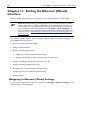
Chapter 2: Setting up the AT-TQ2403 Management Software..................................................................21
Running Kick Start to Find Access Points on the Network.................................................................21
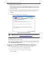
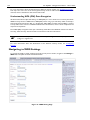
Logging in to the AT-TQ2403 Management Software..........................................................................23
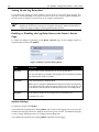
Configuring the Basic Settings and Starting the Wireless Network...................................................25
Configuring the Basic Settings .................................................................................................................25
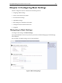
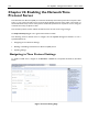
Chapter 3: Configuring Basic Settings..............................................................................................................27
Navigating to Basic Settings ........................................................................................................................27
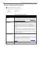
Review / Describe the Access Point .........................................................................................................28
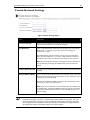
Provide Network Settings...........................................................................................................................29
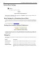
Update Basic Settings ...................................................................................................................................30
Basic Settings for a Standalone Access Point ..........................................................................................30
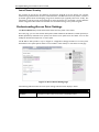
Setting User Interface Scheme Preferences ............................................................................................30
Navigation.......................................................................................................................................................30
Chapter 4: Managing Access Points and Clusters .........................................................................................31
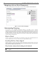
Navigating to Access Points Management ...............................................................................................32
Understanding Clustering............................................................................................................................32
What is a Cluster? .....................................................................................................................................32
How Many APs Can a Cluster Support? ...............................................................................................32
Only the same country domain setting can be clustered. .................................................................32
What Kinds of APs Can Cluster Together? .........................................................................................33
Which Settings are Shared as Part of the Cluster Configuration and Which Are Not? ............33
Cluster Formation......................................................................................................................................34
Cluster Size and Membership..................................................................................................................34
Intra-Cluster Security................................................................................................................................35
Understanding Access Point Settings........................................................................................................35
Modifying the Location Description..........................................................................................................36
Setting the Cluster Name............................................................................................................................36
Stopping Clustering.......................................................................................................................................37
Starting Clustering ........................................................................................................................................37
AT-TQ2403 Management Software User's Guide
Navigating to Configuration Information for a Specific AP and Managing Standalone APs...........37
Navigating to an AP by Using its IP Address in a URL..........................................................................38
Chapter 5: Managing User Accounts ...............................................................................................................39
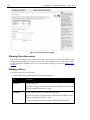
Navigating to User Management for Clustered Access Points ...........................................................39
Viewing User Accounts ...............................................................................................................................40
Adding a User ................................................................................................................................................40
Editing a User Account ................................................................................................................................41
Enabling and Disabling User Accounts .....................................................................................................41
Enabling a User Account ..........................................................................................................................41
Disabling a User Account.........................................................................................................................42
Removing a User Account ..........................................................................................................................42
Backing Up and Restoring a User Database............................................................................................42
Backing Up the User Database ...............................................................................................................42
Restoring a User Database from a Backup File ...................................................................................42
Chapter 6: Session Monitoring..........................................................................................................................43
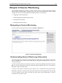
Navigating to Session Monitoring..............................................................................................................43
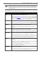
Understanding Session Monitoring Information.....................................................................................43
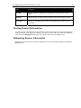
Sorting Session Information........................................................................................................................45
Refreshing Session Information..................................................................................................................45
Chapter 7: Channel Management .....................................................................................................................46
Navigating to Channel Management .........................................................................................................46
Understanding Channel Management.......................................................................................................47
How it Works in a Nutshell ....................................................................................................................47
For the Curious: More About Overlapping Channels .......................................................................47
Example: A Network Before and After Channel Management........................................................47
Configuring and Viewing Channel Management Settings......................................................................48
Stopping/Starting Automatic Channel Assignment .............................................................................48
Viewing Current Channel Assignments and Setting Locks ...............................................................49
Update Current Channel Settings (Manual Setting) ...........................................................................49
Viewing Last Proposed Set of Changes .................................................................................................50
Configuring Advanced Settings (Customizing and Scheduling Channel Plans)..............................50
Update Advanced Settings .......................................................................................................................51
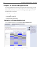
Chapter 8: Wireless Neighborhood...............................................................................................................52
Navigating to Wireless Neighborhood ....................................................................................................52
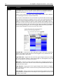
Understanding Wireless Neighborhood Information ...........................................................................53
Viewing Wireless Neighborhood ..............................................................................................................53
Viewing Details for a Cluster Member.....................................................................................................55
Chapter 9: Configuring Security .......................................................................................................................57
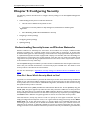
Understanding Security Issues on Wireless Networks ........................................................................57
How Do I Know Which Security Mode to Use? ................................................................................57
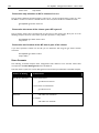
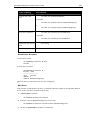
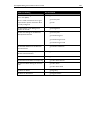
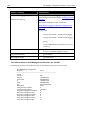
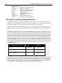
Comparison of Security Modes for Key Management, Authentication and Encryption Algorithms
.......................................................................................................................................................................58
Does Prohibiting the Broadcast SSID Enhance Security? ..................................................................62
Navigating to Security Settings...................................................................................................................62
Configuring Security Settings......................................................................................................................62
Broadcast SSID, Station Isolation, and Security Mode .......................................................................63
None (Plain-text) .......................................................................................................................................64
Static WEP...................................................................................................................................................65
IEEE 802.1x..................................................................................................................................................69
WPA Personal ............................................................................................................................................71
WPA Enterprise .........................................................................................................................................73
Updating Settings ..........................................................................................................................................77
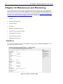
Chapter 10: Maintenance and Monitoring ......................................................................................................78
Interfaces ........................................................................................................................................................78
7
8
AT-TQ2403 - Management Software - User's Guide
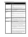
Ethernet (Wired) Settings...........................................................................................................................79
Wireless Settings...........................................................................................................................................79
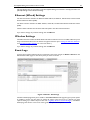
Event Logs.......................................................................................................................................................79
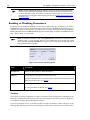
Enabling or Disabling Persistence ..............................................................................................................80
Severity.........................................................................................................................................................80
Depth............................................................................................................................................................81
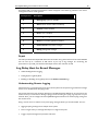
Log Relay Host for Kernel Messages ........................................................................................................81
Understanding Remote Logging ..............................................................................................................81
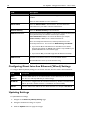
Setting Up the Log Relay Host ................................................................................................................82
Enabling or Disabling the Log Relay Host on the Status > Events Page .........................................82
Update Settings...........................................................................................................................................82
Events Log....................................................................................................................................................83
Transmit/Receive Statistics .........................................................................................................................83
Associated Wireless Clients.......................................................................................................................84
Link Integrity Monitoring..........................................................................................................................85
Neighboring Access Points .........................................................................................................................85
Chapter 11: Setting the Ethernet (Wired) Interface ...................................................................................88
Navigating to Ethernet (Wired) Settings..................................................................................................88
Setting the DNS HostName .......................................................................................................................89
Enabling or Disabling Guest Access ..........................................................................................................90
Configuring an Internal LAN and a Guest Network ..........................................................................90
Enabling or Disabling Guest Access and Choosing a Virtual Network ..........................................90
Enabling or Disabling Virtual Wireless Networks on the AP..............................................................90
Enabling or Disabling Standby Power Saving ...........................................................................................91
Configuring LAN or Internal Interface Ethernet Settings.....................................................................91
Configuring Guest Interface Ethernet (Wired) Settings .......................................................................94
Updating Settings...........................................................................................................................................94
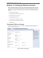
Chapter 12: Setting the Wireless Interface...................................................................................................95
Navigating to Wireless Settings .................................................................................................................95
Configuring 802.11d Regulatory Domain Support.................................................................................96
802.11h Regulatory Domain Control .......................................................................................................96
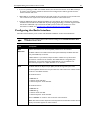
Configuring the Radio Interface .................................................................................................................97
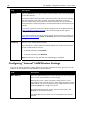
Configuring "Internal" LAN Wireless Settings........................................................................................98
Configuring "Guest" Network Wireless Settings...................................................................................99
Updating Settings...........................................................................................................................................99
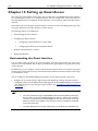
Chapter 13: Setting up Guest Access ........................................................................................................... 100
Understanding the Guest Interface ........................................................................................................ 100
Configuring the Guest Interface ............................................................................................................. 101
Configuring a Guest Network on a Virtual LAN ............................................................................. 101
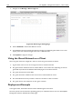
Configuring the Welcome Screen (Captive Portal)......................................................................... 101
Using the Guest Network as a Client ................................................................................................... 102
Deployment Example ................................................................................................................................ 102
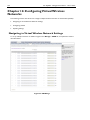
Chapter 14: Configuring Virtual Wireless Networks................................................................................ 104
Navigating to Virtual Wireless Network Settings............................................................................... 104
Configuring VLANs.................................................................................................................................... 105
Updating Settings........................................................................................................................................ 106
Chapter 15: Configuring Radio Settings ...................................................................................................... 107
Understanding Radio Settings.................................................................................................................. 107
Navigating to Radio Settings .................................................................................................................... 107
Updating Settings........................................................................................................................................ 113
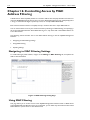
Chapter 16: Controlling Access by MAC Address Filtering .................................................................... 114
Navigating to MAC Filtering Settings..................................................................................................... 114
Using MAC Filtering .................................................................................................................................. 114
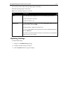
Updating Settings........................................................................................................................................ 115
AT-TQ2403 Management Software User's Guide
Chapter 17: Load Balancing ............................................................................................................................ 116
Understanding Load Balancing ................................................................................................................ 116
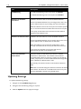
Identifying the Imbalance: Overworked or Under-utilized Access Points.................................. 116
Specifying Limits for Utilization and Client Associations................................................................ 116
Load Balancing and QoS ........................................................................................................................ 117
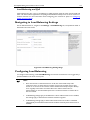
Navigating to Load Balancing Settings ................................................................................................... 117
Configuring Load Balancing...................................................................................................................... 117
Updating Settings ....................................................................................................................................... 118
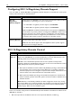
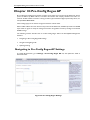
Chapter 18: Pre-Config Rogue AP ................................................................................................................ 119
Navigating to Pre-Config Rogue AP Settings ....................................................................................... 119
Using Pre-Config Rogue AP..................................................................................................................... 120
Updating Settings ....................................................................................................................................... 120
Chapter 19: Configuring Quality of Service (QoS) .................................................................................... 121
Understanding QoS ................................................................................................................................... 121
QoS and Load Balancing ........................................................................................................................ 121
802.11e and WMM Standards Support .............................................................................................. 122
QoS Queues and Parameters to Coordinate Traffic Flow ............................................................ 122
802.1q and DSCP tags............................................................................................................................ 125
Navigating to QoS Settings ...................................................................................................................... 126
Configuring QoS Queues......................................................................................................................... 126
Configuring AP EDCA Parameters ..................................................................................................... 127
Enabling/Disabling Wi-Fi Multimedia................................................................................................... 129
Configuring Station EDCA Parameters.............................................................................................. 129
Updating Settings ....................................................................................................................................... 131
Chapter 20: Configuring the Wireless Distribution System (WDS)...................................................... 132
Understanding the Wireless Distribution System .............................................................................. 132
Using WDS to Bridge Distant Wired LANs ..................................................................................... 132
Using WDS to Extend the Network Beyond the Wired Coverage Area .................................. 133
Security Considerations Related to WDS Links ................................................................................. 133
Understanding Static (WEP) Data Encryption .................................................................................. 133
Understanding WPA (PSK) Data Encryption.................................................................................... 134
Navigating to WDS Settings .................................................................................................................... 134
Configuring WDS Settings ....................................................................................................................... 135
Updating Settings ....................................................................................................................................... 137
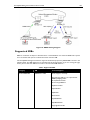
Chapter 21: Configuring Simple Network Management Protocol (SNMP) on the AP ...................... 138
Understanding SNMP................................................................................................................................ 138
Supported MIBs.......................................................................................................................................... 139
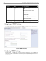
Navigating to SNMP Settings ................................................................................................................... 140
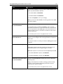
Configuring SNMP Settings...................................................................................................................... 140
Configuring SNMP Traps....................................................................................................................... 142
Updating SNMP Settings........................................................................................................................... 143
Chapter 22: Enabling the Network Time Protocol Server ...................................................................... 144
Navigating to Time Protocol Settings.................................................................................................... 144
Enabling or Disabling a Network Time Protocol (NTP) Server ...................................................... 145
Updating Settings ....................................................................................................................................... 145
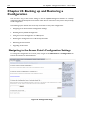
Chapter 23: Backing up and Restoring a Configuration............................................................................ 146
Navigating to the Access Point’s Configuration Settings................................................................... 146
Resetting Factory Default Configuration .............................................................................................. 147
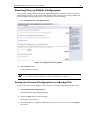
Saving the Current Configuration to a Backup File ............................................................................ 147
Restoring the Configuration from a Previously Saved File................................................................ 148
Rebooting the Access Point..................................................................................................................... 148
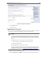
Upgrading the Firmware........................................................................................................................... 149
Update....................................................................................................................................................... 150
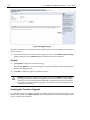
Verifying the Firmware Upgrade.......................................................................................................... 150
9
10
AT-TQ2403 - Management Software - User's Guide
Appendix A: Security Settings on Wireless Clients and RADIUS Server Setup................................. 151
Network Infrastructure and Choosing Between Built-in or External Authentication Server ... 152
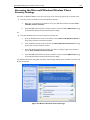
Make Sure the Wireless Client Software is Up-to-Date ................................................................... 152
Accessing the Microsoft Windows Wireless Client Security Settings ........................................... 153
Configuring a Client to Access an Unsecure Network (No Security) ........................................... 154
Configuring Static WEP Security on a Client ....................................................................................... 155
Configuring IEEE 802.1x Security on a Client ...................................................................................... 157
IEEE 802.1x Client Using EAP/PEAP ................................................................................................... 158
IEEE 802.1x Client Using EAP/TLS Certificate.................................................................................. 161
Configuring WPA/WPA2 Enterprise (RADIUS) Security on a Client ............................................ 165
WPA/WPA2 Enterprise (RADIUS) Client Using EAP-TLS Certificate........................................ 169
WPA/WPA2 Enterprise (RADIUS) Client Using EAP-SIM Certificate........................................ 172
Configuring WPA/WPA2 Personal (PSK) Security on a Client........................................................ 175
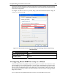
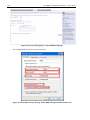
Configuring an External RADIUS Server to Recognize the AT-TQ2403 Wireless Access Point176
Obtaining a TLS-EAP Certificate for a Client.............................................................................................. 180
Configuring RADIUS Server for VLAN tags......................................................................................... 183
Configuring a RADIUS server .............................................................................................................. 183
Appendix B: Troubleshooting......................................................................................................................... 185
Wireless Distribution System (WDS) Problems and Solutions ....................................................... 185
Cluster Recovery ....................................................................................................................................... 185
Reboot or Reset Access Point ............................................................................................................. 185
BootLoader Recovery............................................................................................................................... 186
Appendix C: Command Line Interface (CLI) for AP Configuration....................................................... 187
Comparison of Settings Configurable with the CLI and Web UI .................................................... 188
How to Access the CLI for an Access Point........................................................................................ 190
Telnet Connection to the AP............................................................................................................... 190
SSH Connection to the AP ................................................................................................................... 191
Quick View of Commands and How to Get Help.............................................................................. 192
Commands and Syntax........................................................................................................................... 192
Getting Help on Commands at the CLI ............................................................................................. 195
Ready to Get Started?............................................................................................................................ 197
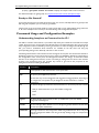
Command Usage and Configuration Examples.................................................................................... 197
Understanding Interfaces as Presented in the CLI........................................................................... 197
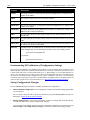
Understanding CLI Validation of Configuration Settings ................................................................ 198
Saving Configuration Changes .............................................................................................................. 198
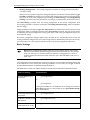
Basic Settings............................................................................................................................................ 199
Access Point and Cluster Settings ....................................................................................................... 203
User Accounts ......................................................................................................................................... 204
Status ......................................................................................................................................................... 206
Ethernet (Wired) Interface ................................................................................................................... 216
Wireless Interface................................................................................................................................... 220
Guest Access............................................................................................................................................ 220
Enable/Configure Guest Login Welcome Page ................................................................................. 222
Configuring Virtual Wireless Networks (VWNs)............................................................................ 223
Example: Configuring VWNs................................................................................................................ 227
Security...................................................................................................................................................... 228
Radio Settings........................................................................................................................................... 244
MAC Filtering........................................................................................................................................... 253
Load Balancing ......................................................................................................................................... 255
Quality of Service.................................................................................................................................... 256
Wireless Distribution System (WDS) ................................................................................................ 262
Simple Network Management Protocol (SNMP) ............................................................................. 264
Time Protocol.......................................................................................................................................... 265
Pre-Config Rogue AP ............................................................................................................................. 266
Reboot the AP ......................................................................................................................................... 266
Reset the AP to Factory Defaults........................................................................................................ 267
Upgrade the Firmware ........................................................................................................................... 267
Keyboard Shortcuts and Tab Completion Help.................................................................................. 268
AT-TQ2403 Management Software User's Guide
Keyboard Shortcuts................................................................................................................................ 268
Tab Completion and Help..................................................................................................................... 269
CLI Classes and Properties Reference .................................................................................................. 272
Glossary .............................................................................................................................................................. 274
11
12
AT-TQ2403 - Management Software - User's Guide
FIGURES
Figure 1: Kick Start Welcome Dialog Box ............................................................................................................... 22
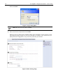
Figure 2: Kick Start Search Results Dialog Box....................................................................................................... 22
Figure 3: Administration Dialog Box ......................................................................................................................... 23
Figure 4: Log-in Dialog Box ......................................................................................................................................... 24
Figure 5: Basic Settings Page ........................................................................................................................................ 24
Figure 6: Basic Settings Page ........................................................................................................................................ 27
Figure 7: Basic Settings Page Step 1 ........................................................................................................................... 28
Figure 8: Basic Settings Step 2..................................................................................................................................... 29
Figure 9: Basic Settings Page Step 3 ........................................................................................................................... 30
Figure 10: Web User Interface Setting...................................................................................................................... 30
Figure 11: Access Points Setting Page........................................................................................................................ 32
Figure 12: Access Points Setting Page........................................................................................................................ 35
Figure 13: User Management Page ............................................................................................................................. 40
Figure 14: Cluster Settings Page Detail ..................................................................................................................... 41
Figure 15: Sessions Setting Page ................................................................................................................................. 43
Figure 16: Channel Management Setting Page ......................................................................................................... 46
Figure 17: Before Channel Management Enable...................................................................................................... 47
Figure 18: After Channel Management Enable......................................................................................................... 48
Figure 19: After Channel Management Enable......................................................................................................... 49
Figure 20: Wireless Neighborhood Page.................................................................................................................. 52
Figure 21: Cluster Member Setting Detail................................................................................................................ 55
Figure 22: Security Setting Page.................................................................................................................................. 62
Figure 23: Security Setting Page – None (Plain-text) Setting................................................................................ 64
Figure 24: Security Setting Page – Static WEP Setting ........................................................................................... 65
Figure 25: Security Setting Page – Static WEP Setting Example........................................................................... 68
Figure 26: Providing a Wireless Client with a WEP Key....................................................................................... 68
Figure 27: Example of Using Multiple WEP Keys and Transfer Key Index on Client Stations...................... 69
Figure 28: Security Setting Page – IEEE802.1x Setting Page.................................................................................. 70
Figure 29: Security Setting Page – WPA Personal Setting Page ........................................................................... 72
Figure 30: Security Setting Page – WPA Enterprise Setting Page........................................................................ 74
Figure 31: Status - Interfaces Page.............................................................................................................................. 78
Figure 32: Status - Event Page ..................................................................................................................................... 79
Figure 33: Persistence Setting Detail ......................................................................................................................... 80
Figure 34: Relay Log Host Setting Detail .................................................................................................................. 82
Figure 35: Transmit / Receive Page ............................................................................................................................ 83
Figure 36: Client Associations Page ........................................................................................................................... 84
Figure 37: Neighboring Access Points Page ............................................................................................................. 85
AT-TQ2403 Management Software User's Guide
13
Figure 38: Ethernet (Wired) Settings Page............................................................................................................... 89
Figure 39: Wireless Settings Page............................................................................................................................... 95
Figure 40: Guest Login Setting Page ........................................................................................................................ 102
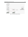
Figure 41: Guest Network Diagram Example ....................................................................................................... 103
Figure 42: VWN Page ................................................................................................................................................. 104
Figure 43: Radio Setting Page .................................................................................................................................... 108
Figure 44: MAC Filtering Setting Page..................................................................................................................... 114
Figure 45: Load Balancing Settings Page.................................................................................................................. 117
Figure 46: Pre-Config Rogue AP Page ..................................................................................................................... 119
Figure 47: Backoff timer Diagram............................................................................................................................. 124
Figure 48: 802.1q Tag Retrieving Flow Diagram ................................................................................................... 125
Figure 49: QoS Setting Page ...................................................................................................................................... 126
Figure 50: Bridge Distant Wired LAN by WDS Diagram................................................................................... 133
Figure 51: WDS Setting Page .................................................................................................................................... 134
Figure 52: SNMP Setting Diagram ............................................................................................................................ 139
Figure 53: SNMP Setting Page ................................................................................................................................... 140
Figure 54: Time Setting Page ..................................................................................................................................... 144
Figure 55: Configuration Page................................................................................................................................... 146
Figure 56: Configuration Setting Detail................................................................................................................... 147
Figure 57: Configuration Setting Page ..................................................................................................................... 149
Figure 58: Upgrade Page............................................................................................................................................. 150
Figure 59: Wireless Network Connection Page ................................................................................................... 153
Figure 60: Wireless Network Connection Properties Page............................................................................... 154
Figure 61: Wireless Network Connection Properties Setting – No Security Setting Association Tab.... 155
Figure 62: Security Setting Page – Static WEP Setting Page ............................................................................... 156
Figure 63: Client Side Security Setting - Static WEP Setting Detail Association Tab.................................... 156
Figure 64: Security Setting Page – IEEE802.1x Setting Page................................................................................ 158
Figure 65: Client Side Security Setting - IEEE802.1x Security Setting Detail .................................................. 159
Figure 66: Security Setting Page – IEEE802.1x Setting Page................................................................................ 162
Figure 67: Client Side Security Setting - IEEE802.1x Security Setting Detail .................................................. 163
Figure 68: Security Setting Page – WPA Enterprise Setting Page...................................................................... 166
Figure 69: User Management Page........................................................................................................................... 166
Figure 70: Client Side Security Setting – WPA Enterprise Setting Detail........................................................ 167
Figure 71: Security Setting Page – WPA Enterprise Setting Page...................................................................... 170
Figure 72: Client Side Security Setting – WPA Setting Detail............................................................................ 171
Figure 73: Security Setting Page – WPA Enterprise Setting Page...................................................................... 173
Figure 74: Client Side Security Setting – WPA Setting Detail............................................................................ 174
Figure 75: Security Setting Page – WPA Personal Setting Page ......................................................................... 175
Figure 76: Client Side Security Setting – WPA Personal Setting Detail........................................................... 175
Figure 77: Radius Server – Internet Authentication Service .............................................................................. 178
14
AT-TQ2403 - Management Software - User's Guide
Figure 78: Radius Server Setting – Input New Radius Client ............................................................................. 178
Figure 79: Radius Server Setting – New Radius Client Setting .......................................................................... 179
Figure 80: Radius Server............................................................................................................................................. 179
Figure 81: Web Security Alert .................................................................................................................................. 180
Figure 82: Welcome Message from Certification Server .................................................................................... 181
Figure 83: Radius Server Log-in Page....................................................................................................................... 181
Figure 84: User Certification Installation – Request a Certification ................................................................. 181
Figure 85: User Certification Installation – Identifying Information.................................................................. 182
Figure 86: User Certification Installation – Submit............................................................................................... 182
Figure 87: User Certification Installation – Certification Issued........................................................................ 183
Figure 88: User Certification Installation – Certification Installed .................................................................... 183
Figure 89: SSH Application Setting – PuTTY as an Eample................................................................................. 191
Figure 90: Kick Start Search Results Dialog Box................................................................................................... 273
AT-TQ2403 Management Software User's Guide
15
Preface
Purpose of This Guide
This guide is intended for customers and/or network administrators who are responsible for installing
and maintaining the AT-TQ2403 Management Software.
How This Guide is Organized
This guide contains instructions on how to install AT-TQ2403 Management Software. This preface
contains the following sections?
Chapter 1 Overview, describes the features, LEDs and ports on the equipment.
Chapter 2 Installation, describes how to install and configure the equipment.
Chapter 3 Troubleshooting, describes what you should do when the device does not operate
correctly.
Document Conventions
This guide uses several conventions that you should become familiar with before you begin to install the
product:
Note
A note provides additional information. Please go to the Allied Telesis website
http://www.alliedtelesis.com for the translated safety statement in your language.
Warning
A warning indicates that performing or omitting a specific action may result in bodily injury.
Caution
A caution indicates that performing or omitting a specific action may result in equipment
damage or loss of data.
16
AT-TQ2403 - Management Software - User's Guide
Contacting Allied Telesis
This section provides Allied Telesis contact information for technical support as well as sales and
corporate information.
Online Support
You can request technical support online by accessing the Allied Telesis Knowledge Base:
http://www.alliedtelesis.com/support/kb.aspx. You can use the Knowledge Base to submit
questions to our technical support staff and review answers to previously asked questions.
Email and Telephone Support
For Technical Support via email or telephone, refer to the Allied Telesis web site at
http://www.alliedtelesis.com. Select your country from the list on the website and then select the
appropriate tab.
Warranty
For product registration and warranty conditions
http://www.alliedtelesis.com/support/warranty/.
please
visit
Allied
Telesis
website:
Where to Find Web-based Guides
The installation and user guides for all Allied Telesis products are available for viewing in portable
document format (PDF) from our website at http://www.alliedtelesis.com.
Returning Products
Products for return or repair must first be assigned a return materials authorization (RMA) number. A
product sent to Allied Telesis without an RMA number will be returned to the sender at the sender’s
expense. For instructions on how to obtain an RMA number, go to the Support section on our website
at http://www.alliedtelesis.com.
Sales or Corporate Information
You can contact Allied Telesis for sales or corporate information through our web site at
http://www.alliedtelesis.com.
Management Software Updates
New releases of management software for our managed products are available from the following
Internet sites:
Allied Telesis web site: http://www.alliedtelesis.com
Allied Telesis FTP server: ftp://ftp.alliedtelesis.com
If the FTP server prompts you to log on, enter “anonymous” as the user name and your email address as
the password.
Tell Us What You Think
If you have any comments or suggestions on how we might improve this or other Allied Telesis
documents, please contact us at http://www.alliedtelesis.com.
AT-TQ2403 Management Software User's Guide
17
Chapter 1: Preparing to Set Up the AT-TQ2403
Wireless Access Point
Before you plug in and boot a new AT-TQ2403 Management Software, review the following sections for
a quick check of required hardware components, software, client configurations, and compatibility issues.
Make sure you have everything you need ready to go for a successful launch and test of your new (or
extended) wireless network.
This chapter contains the following sections:
Setting Up the Administrator’s Computer
Setting Up the Wireless Client Computers
Understanding Dynamic and Static IP Addressing on the AT-TQ2403 Management Software
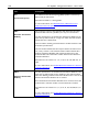
Setting Up the Administrator’s Computer
You configure and administer AT-TQ2403 Management Software with the Kick Start utility (which you
run from the CD) and through a web-based user interface (UI). In order to successfully start the
management software, the administrator’s computer must be set up with the following hardware and
software components:
Ethernet connection
The computer used to configure the first AT-TQ2403 Management Software with Kick Start must be
connected to the access point, either directly or through a hub, by an Ethernet cable.
Wireless Connection to the Network
After you initially configure and launch the first AT-TQ2403 Management Software, you can make
further configuration changes through the management software using a wireless connection to the
“internal” network. This configuration includes:
Portable or built-in Wi-Fi client adapter that supports one or more of the IEEE 802.11
modes in which you plan to run the access point. (IEEE 802.11a, 802.11b, 802.11g, and
802.11a Turbo modes are supported.)
Wireless client software such as Microsoft Windows XP or Funk Odyssey wireless client
configured to associate with the AT-TQ2403 Management Software.
For more details about the Wi-Fi client setup, see “Setting Up the Wireless Client Computers”.
Web browser/operating system
Configuration and administration of the AT-TQ2403 Management Software is provided through a
Web-based user interface hosted on the access point. Allied Telesis recommends using one of the
following supported web browsers to access the AT-TQ2403 Management Software:
Microsoft Internet Explorer version 5.5 or greater (with up-to-date patch level for either
major version) on Microsoft Windows XP or Microsoft Windows 2000
Netscape Mozilla 1.7.x on Redhat Linux version 2.4
18
AT-TQ2403 - Management Software - User's Guide
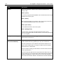
The administration web browser must have JavaScript enabled to support the interactive features of
the administration interface. It must also support HTTP uploads to use the firmware upgrade feature.
AT-TQ2403 Software and Documentation CD
This CD contains the Kick Start utility and the software documentation. You can run the Kick Start
utility on Windows (only Windows 2000, XP, Vista, 2000 Server and 2003 Server) laptop or
computer that is connected to the access point (via wired or wireless connection). It detects
AT-TQ2403 Management Software on the network. The wizard steps you through initial
configuration of new access points, and provides a link to the AT-TQ2403 Management Software
where you finish the basic setup process in a step-by-step mode and launch the network.
For more about using Kick Start, see “Running Kick Start to Find Access Points on the Network”.
CD-ROM Drive
The administrator’s computer must have a CD-ROM drive to run the Kick Start application on the
AT-TQ2403 Software and Documentation CD.
Security Settings
Ensure that security is disabled on the wireless client used to initially configure the access point.
Setting Up the Wireless Client Computers
The AT-TQ2403 Management Software provides wireless access to any client with a properly configured
Wi-Fi client adapter for the 802.11 mode in which the access point is running.
Multiple client operating systems are supported. Clients can be laptops or desktops, personal digital
assistants (PDAs), or any other hand-held, portable or stationary device equipped with a Wi-Fi adapter
and supporting drivers.
In order to connect to the access point, wireless clients need the following software and hardware:
Wi-Fi Client Adapter
Portable or built-in Wi-Fi client adapter that supports one or more of the IEEE 802.11 modes in
which you plan to run the access point. (IEEE 802.11a, 802.11b, 802.11g, and 802.11a Turbo modes
are supported.)
Wi-Fi client adapters vary considerably. The adapter can be a PC card built in to the client device, a
portable PCMCIA or PCI card (types of NICs), or an external device such as a USB or Ethernet
adapter that you connect to the client by means of a cable.
The AT-TQ2403 Wireless Access Point supports 802.11a/g modes. The fundamental requirement
for clients is that they all have configured adapters that match the 802.11 a/g mode.
Wireless Client Software
Client software such as Microsoft Windows Supplicant or Funk Odyssey wireless client configured to
associate with the AT-TQ2403 Management Software.
Client Security Settings
Security should be disabled on the client used to do initial configuration of the access point.
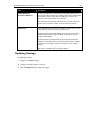
If the Security mode on the access point is set to anything other than plain-text, wireless clients will
need to set a profile to the authentication mode used by the access point and provide a valid
AT-TQ2403 Management Software User's Guide
19
username and password, certificate, or similar user identity proof. Security modes are Static WEP,
IEEE 802.1x, WPA with RADIUS server, and WPA-PSK.
For information on configuring security on the access point, see “Configuring Security”.
Understanding Dynamic and Static IP Addressing on the
AT-TQ2403 Management Software
AT-TQ2403 Management Software are designed to auto-configure, with very little setup required for the
first access point and no configuration required for additional access points subsequently joining a
pre-configured cluster.
How Does the Access Point Obtain an IP Address at Start-up?
When you deploy the access point, it looks for a network DHCP server and, if it finds one, obtains an IP
address from the DHCP server. If no DHCP server is found on the network, the access point will
continue to use its default static IP address (192.168.1.230) until you reassign it a new static IP address
(and specify a static IP addressing policy) or until a DHCP server is brought online.
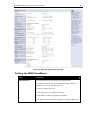
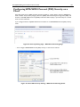
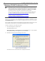
When you run Kick Start, it discovers the AT-TQ2403 Management Software on the network and lists
their IP addresses and MAC addresses. Kick Start also provides a link to the administration web pages of
each access point using the IP address in the URL. (For more information about the Kick Start utility, see
“Running Kick Start to Find Access Points on the Network”.)
Dynamic IP Addressing
The AT-TQ2403 Management Software generally expects that a DHCP server is running on the network
where the access point is deployed. Most home and small business networks already have DHCP service
provided either via a gateway device or a centralized server. However, if no DHCP server is present on
the internal network, the access point will use the default static IP address for first time startup.
Similarly, wireless clients and other network devices (such as printers) will receive their IP addresses
from the DHCP server, if there is one. If no DHCP server is present on the network, you must manually
assign static IP addresses to your wireless clients and other network devices.
The Guest network must have a DHCP sever.
Static IP Addressing
The AT-TQ2403 Management Software is shipped with a default static IP address of 192.168.1.230. If no
DHCP server is found on the network, the access point retains this static IP address at first-time startup.
After the access point starts up, you have the option of specifying a static IP addressing policy on
AT-TQ2403 Management Software and assigning static IP addresses to access points on the internal
network using the management software. (See information about the Connection Type field and related
fields in “Setting the Ethernet (Wired) Interface”.)
Caution: If you do not have a DHCP server on the internal network and do not plan to use
one, the first thing you must do after bringing up the access point is change the Connection
Type from DHCP to Static IP. You can either assign a new Static IP address to the access point
or continue using the default address. Allied Telesis recommends assigning a new Static IP
address so that if later you bring up another AT-TQ2403 Management Software on the same
network, the IP address for each access point will be unique.
20
AT-TQ2403 - Management Software - User's Guide
Recovering an IP Address
If you experience trouble communicating with the access point, you can recover a static IP address by
resetting the access point configuration to the factory defaults (see “Backing up and Restoring a
Configuration”), or you can get a dynamically assigned address by connecting the access point to a
network that has DHCP.
AT-TQ2403 Management Software User's Guide
21
Chapter 2: Setting up the AT-TQ2403
Management Software
Setting up and deploying one or more AT-TQ2403 Management Software is in effect creating and
launching a wireless network. The Kick Start utility and corresponding AT-TQ2403 Management
Software Basic Settings web page simplify this process. This chapter contains procedures for setting up
your AT-TQ2403 Management Software and the resulting wireless network.
This chapter includes the following procedures:
Running Kick Start to Find Access Points on the Network
Logging in to the AT-TQ2403 Management Software
Configuring the Basic Settings and Starting the Wireless Network
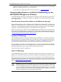
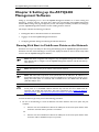
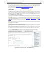
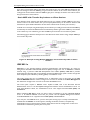
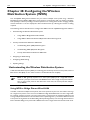
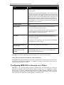
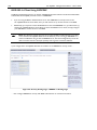
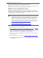
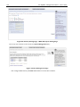
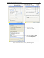
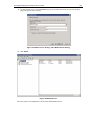
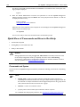
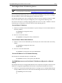
Running Kick Start to Find Access Points on the Network
Kick Start is an easy-to-use utility for discovering and identifying new AT-TQ2403 Management Software.
Kick Start scans the network looking for access points, displays ID details on those it finds, and provides
access to the AT-TQ2403 Management Software.
Note: Kick Start recognizes and configures only AT-TQ2403 Management Software. Kick
Start will not find or configure non AT-TQ2403 Management Software and will not find any
other devices.
Note: Run Kick Start only in the subnet of the internal network.
Note: Kick Start finds only those access points that have IP addresses. IP addresses are
dynamically assigned to access points if you have a DHCP server running on the network. If you
deploy the access point on a network with no DHCP server, the default static IP address
(192.168.1.230) is used.
Caution: Use caution with non-DHCP enabled networks: Do not deploy more than one new
access point on a non-DHCP network because they will use the same default static IP
addresses and conflict with each other. (For more information, see “Setting the Ethernet
(Wired) Interface” and “How Does the Access Point Obtain an IP Address at Start-up?”.)
To start the discovery process, perform the following procedure:
1. Do one of the following to create an Ethernet connection between the access point and your
computer:
Connect one end of an Ethernet cable to the LAN port on the access point and the other
end to the same hub where your PC is connected.
Or
Connect one end of an Ethernet cable to the LAN port on the access point and the other
end of the cable to the Ethernet port on your PC.
22
AT-TQ2403 - Management Software - User's Guide
2. Insert the AT-TQ2403 Wireless Access Point CD into the CD-ROM drive on your computer.
The Kick Start Welcome dialog box is displayed, as shown in Figure 1
Figure 1: Kick Start Welcome Dialog Box
3. Click Next to search for access points
Wait for the search to complete, or until Kick Start has found your new access points, as shown in
Figure 2.
Figure 2: Kick Start Search Results Dialog Box
Note: If no access points are found, Kick Start indicates this and presents some
troubleshooting information about your LAN and power connections. After you check the
hardware power and Ethernet connections, you can click Back to search again for access
points.
AT-TQ2403 Management Software User's Guide
23
4. Review the list of access points found
Kick Start detects the IP addresses of AT-TQ2403 Management Software. Access points are listed
with their locations, media access control (MAC) addresses, and IP addresses, as shown in Figure 2.
If you are installing the first access point on a single-access-point network, only one entry is
displayed on this screen.
5. Verify the MAC addresses against the hardware labels for each access point. This will be especially
helpful later in providing or modifying the descriptive Location name for each access point.
6. Click Next
The Administration dialog box opens, as shown in Figure 3.
Figure 3: Administration Dialog Box
Note: Kick Start provides a link to the AT-TQ2403 Management Software web pages via
the IP address of the first access point of each model. (For more information about model
types and clustering see “What Kinds of APs Can Cluster Together?”.)
The AT-TQ2403 Management Software is a centralized management tool that you can access through
the IP address for any access point in a cluster.
After your other access points are configured, you can also link to the AT-TQ2403 Management
Software web pages using the IP address for any of the other AT-TQ2403 Management Software, for
example http://IPAddressOfAccessPoint.
Logging in to the AT-TQ2403 Management Software
To access the AT-TQ2403 Management Software, perform the following procedure:
7. In the Kick Start Administration dialog box, click Administration
You are prompted for a user name and password, as shown in Figure 4.
Username: manager
24
AT-TQ2403 - Management Software - User's Guide
Password: friend
Figure 4: Log-in Dialog Box
Note: The user name can not be modified.
8. Enter the username and password and click OK
When you log in for the first time, the Basic Settings page is displayed, as shown in Figure 5. This
page displays the global settings for all access points that are members of the cluster and, if you
specify automatic configuration, for any new access points that you add later.
Figure 5: Basic Settings Page
AT-TQ2403 Management Software User's Guide
25
Configuring the Basic Settings and Starting the Wireless
Network
Provide a minimal set of configuration information by defining the basic settings for your wireless
network. These settings are all available on the Basic Settings page in the AT-TQ2403 Management
Software, and are categorized into steps 1-3 on the web page.
Configuring the Basic Settings
9. To configure initial settings, perform the following procedure:
In the “Review Description of this Access Point” section, configure the following parameters as
necessary:
IP Address
The IP address assigned to this access point. You cannot edit this field because the IP address is
already assigned (either through DHCP or statically through the Ethernet (wired)) settings as
described in “Configuring LAN or Internal Interface Ethernet Settings”.
MAC Address
Shows the MAC address of the access point.
A MAC address is a permanent, unique hardware address for any device that represents an
interface to the network. The MAC address is assigned by the manufacturer. You cannot change the
MAC address. It is provided here for informational purposes as a unique identifier for an interface.
The address shown here is the MAC address for the bridge (br0). This is the address by which the
access point is known externally to other networks.
Firmware Version
Version information about the firmware currently installed on the access point.
As new versions of the AT-TQ2403 Management Software firmware become available, you can
upgrade the firmware on your access points to take advantages of new features and enhancements.
For instructions on how to upgrade the firmware, see “Upgrading the Firmware”.
Time since system-up
It is to show the passed time since system boot up.
10. In the “Provide Network Settings” section, configure the following parameters as necessary:
Current Password
As an immediate first step in securing your wireless network, Allied Telesis recommends that you
change the administrator password from the default which is “friend.” Enter the current
administrator password.
The administrator password must be an alphanumeric string of up to 8 characters. Do not use
special characters or spaces.
New Password
Enter a new administrator password. The characters you enter are displayed as “ * ” characters to
26
AT-TQ2403 - Management Software - User's Guide
prevent others from seeing your password as you type.
Confirm New Password
Retype the new administrator password to confirm that you typed it as you intended.
Network Name (SSID)
Enter a name for the wireless network as a character string. This name will apply to all access points
on this network. As you add more access points, they will share this SSID.
The Service Set Identifier (SSID) is an alphanumeric string of up to 32 characters.
If you are connected as a wireless client to the same access point that you are administering,
resetting the SSID will causes you to lose connectivity to the access point. You will need to
reconnect to the new SSID after you save the new Network Name.
Note: The AT-TQ2403 Management Software is not designed for multiple,
simultaneous configuration changes. If you have a network that includes multiple access
points, and more than one administrator is logged on to the AT-TQ2403 Management
Software’s web pages and making changes to the configuration, all access points in the
cluster will stay in sync but there is no guarantee that all configuration changes specified
by multiple users will be applied.
11. In the Settings section, click Update to apply these settings and deploy the access point as a
wireless network.
After you have the wireless network up and running and have tested against the access point with
some wireless clients, you can add in more layers of security, add users, configure a guest interface,
and fine-tune performance settings. These features are described in the rest of this guide.
AT-TQ2403 Management Software User's Guide
27
Chapter 3: Configuring Basic Settings
The basic configuration tasks are described in the following sections:
Navigating to Basic Settings
Review / Describe the Access Point
Provide Network Settings
Update Basic Settings
Basic Settings for a Standalone Access Point
Setting User Interface Scheme Preferences
Navigation
Navigating to Basic Settings
To configure initial settings, click Basic Settings.
If you type the IP address of the access point into you browser, the Basic Settings page is the default page
that is displayed.
Fill in the fields on the Basic Settings screen as described below.
Figure 6: Basic Settings Page
28
AT-TQ2403 - Management Software - User's Guide
Review / Describe the Access Point
Figure 7: Basic Settings Page Step 1
Field
Description
IP Address
Shows IP address assigned to this access point. This field is not editable
because the IP address is already assigned (either via DHCP, or statically
through the Ethernet Settings page as described in “Configuring Guest
Interface Ethernet (Wired) Settings”).
MAC Address
Shows the MAC address of the access point.
A MAC address is a permanent, unique hardware address for any device
that represents an interface to the network. The MAC address is
assigned by the manufacturer. You cannot change the MAC address. It is
provided here for informational purposes as a unique identifier for an
interface.
The address shown here is the MAC address for the bridge (br0). This is
the address by which the AP is known externally to other networks.
To see MAC addresses for Guest and Internal interfaces on the AP, see
the Status > Interfaces tab.
Firmware Version
Version information about the firmware currently installed on the access
point.
As new versions of the AT-TQ2403 Management Software firmware
become available, you can upgrade the firmware on your access points to
take advantages of new features and enhancements.
For instructions on how to upgrade the firmware, see “Upgrading the
Firmware”.
Time since system-up
It is to show the passed time since system boot up.
AT-TQ2403 Management Software User's Guide
29
Provide Network Settings
Figure 8: Basic Settings Step 2
Field
Description
Current Password
Enter the current administrator password. You must correctly enter the
current password before you are able to change it.
New Password
Enter a new administrator password. The characters you enter will be
displayed as " * " characters to prevent others from seeing your
password as you type.
The Administrator password must be a string of up to 8 characters.
Please do not include space (' ') and any of the characters within the
parenthesis: ("$:<>'&*). The characters you input are case-sensitive.
Note: As an immediate first step in securing your wireless network, we
recommend that you change the administrator password from the
default.
Confirm New Password
Re-enter the new administrator password to confirm that you typed it as
intended.
Network Name (SSID)
Enter a name for the wireless network as a character string. This name
will apply to all access points on this network. As you add more access
points, they will share this SSID.
The Service Set Identifier (SSID) is a string of up to 32 characters. The
characters you input are case-sensitive.
Note: If you are connected as a wireless client to the same AP that you
are administering, resetting the SSID will cause you to lose connectivity
to the AP. You will need to reconnect to the new SSID after you save
this new setting.
Note: The AT-TQ2403 Management Software is not designed for multiple, simultaneous
configuration changes. If you have a network that includes multiple access points, and more
than one administrator is logged on to the Administration Web pages and making changes to
the configuration, all access points in the cluster will stay in sync but there is no guarantee that
all configuration changes specified by multiple users will be applied.
30
AT-TQ2403 - Management Software - User's Guide
Update Basic Settings
Figure 9: Basic Settings Page Step 3
When you have reviewed the new configuration, click Update to apply the settings and deploy the
access points as a wireless network.
Basic Settings for a Standalone Access Point
The Basic Settings tab for a standalone access point indicates only that the current mode is standalone. If
you want to add the current access point to an existing cluster, navigate to the Cluster > Access Point
tab.
For more information see “Starting Clustering”.
Setting User Interface Scheme Preferences
Figure 10: Web User Interface Setting
A design panel appears at the top of every AP Configuration screen enabling you to configure the
appearance of every web page. You can change the layout of tabs on pages by choosing between three
navigation settings.
Navigation
You use the options available in the navigation drop down list to change the layout of the tab options on
your screen.
Option
Description
Horizontal Tabs
Select this option to display all tabs horizontally across the top of the page.
Vertical Tabs
Select this option to display all tabs vertically on the left side of your page.
Drop Down Menu
Select this option to display all tabs horizontally across the top of the page.
Any sub categories will be displayed as a drop down menu beneath the main
tab.
AT-TQ2403 Management Software User's Guide
31
Chapter 4: Managing Access Points and
Clusters
The AT-TQ2403 Management Software shows current basic configuration settings for clustered access
points (location, IP address, MAC address, status, and availability) and provides a way of navigating to the
full configuration for specific APs if they are cluster members.
Standalone access points or those which are not members of this cluster do not show up in this listing. To
configure standalone access points, you must discover or know the IP address of the access point and by
using its IP address in a URL (http://IPAddressOfAccessPoint).
Note: The AT-TQ2403 Management Software is not designed for multiple, simultaneous
configuration changes. If you have a network that includes multiple access points, and more
than one administrator is logged on to the Administration Web pages and making changes to
the configuration, all access points in the cluster will stay in sync but there is no guarantee that
all configuration changes specified by multiple users will be applied.
The following topics are covered:
Navigating to Access Points Management
Understanding Clustering
What is a Cluster?
How Many APs Can a Cluster Support?
Only the same country domain setting can be clustered.
What Kinds of APs Can Cluster Together?
Which Settings are Shared as Part of the Cluster Configuration and Which Are Not?
Cluster Formation
Cluster Size and Membership
Intra-Cluster Security
Understanding Access Point Settings
Modifying the Location Description
Setting the Cluster Name
Stopping Clustering
Starting Clustering
Navigating to Configuration Information for a Specific AP and Managing Standalone APs
Navigating to an AP by Using its IP Address in a URL
32
AT-TQ2403 - Management Software - User's Guide
Navigating to Access Points Management
To view or edit information on access points in a cluster, click the Cluster > Access Points tab.
Figure 11: Access Points Setting Page
Understanding Clustering
A key feature of the AT-TQ2403 Management Software is the ability to form a dynamic,
configuration-aware group (called a cluster) with other AT-TQ2403 Management Software in a network
in the same subnet. Access points can participate in a self-organizing cluster which makes it easier for you
to deploy, administer, and secure your wireless network. The cluster provides a single point of
administration and lets you view the deployment of access points as a single wireless network rather than
a series of separate wireless devices.
What is a Cluster?
A cluster is a group of access points which are coordinated as a single group via AP administration. You
can have multiple clusters on the same subnet if they have different cluster "names".
How Many APs Can a Cluster Support?
Validation testing has verified 15 AP without enable Virtual Wireless Network function on the same
subnet. Validation testing has verified 8 AP with enable 4 Virtual Wireless Network on the same subnet.
In this test case the cluster function works well.
Only the same country domain setting can be clustered.
Note: If the devices are assigned with different country setting, they can not be clustered
together.
AT-TQ2403 Management Software User's Guide
33
What Kinds of APs Can Cluster Together?
A single AT-TQ2403 Wireless Access Point can form a cluster with itself (a "cluster of one") and with
other AT-TQ2403 Wireless Access Points of the same model. In order to be members of the same
cluster, access points must be:
Of the same Country Domain configuration
Compatible devices as designated by the manufacturer (APs must have compatible design features)
Of the same F/W Version
Of the same LAN
On the same Cluster Name
However, it is helpful to understand the clustering behavior for administration purposes:
Access points joining the cluster must be named the same. For more information on setting the
cluster name, see “Setting the Cluster Name”.
Access points of other brands will not join the cluster. These APs should be administered with their
own associated Administration tools.
Which Settings are Shared as Part of the Cluster Configuration and
Which Are Not?
Most configuration settings defined via the AT-TQ2403 Management Software Administration Web
pages will be propagated to cluster members as a part of the cluster configuration.
Settings Shared in the Cluster Configuration
The cluster configuration includes:
Network name (SSID)
Administrator password
User accounts and authentication
Wireless interface settings
Guest Welcome screen settings
Network Time Protocol (NTP) settings
QoS queue (AP EDCA parameters only)
Radio settings
Only Mode, Channel, Fragmentation Threshold, RTS Threshold and Rate Sets are synchronized across
the cluster. Beacon Interval, DTIM Period, Maximum Stations, and Transmit Power do not cluster.
Note: When Channel Planning is enabled, the radio Channel is not synced across the cluster.
See “Stopping/Starting Automatic Channel Assignment”.
34
AT-TQ2403 - Management Software - User's Guide
When Channel Planning is enabled, the radio Channel is not synced across the cluster.
Security settings
MAC address filtering
Settings Not Shared by the Cluster
The few exceptions (settings not shared among clustered access points) are the following, most of which
by nature must be unique:
IP addresses
MAC addresses
Location descriptions
Load Balancing settings
WDS bridges
Ethernet (Wired) Settings, including enabling or disabling Guest access
Guest interface configuration
Settings that are not shared must be configured individually on the Administration pages for each access
point. To get to the Administration pages for an access point that is a member of the current cluster, click
on its IP Address link on the Cluster > Access Points page of the current AP.
Cluster Formation
A cluster is formed when the first AP is deployed with clustering enabled. The AP attempts to
rendezvous with an existing cluster.
If it is unable to locate any other APs on the subnet with the same cluster name, then it establishes a new
cluster on its own.
When AT-TQ2403 enables cluster function, it sends out its configuration file to all the devices in the
clustered group.
If there is more than one AT-TQ2403 in the clustered group, the last-joined AT-TQ2403 shares its
configuration with other AT-TQ2403 in the group.
Cluster Size and Membership
Validation testing has verified 15 AP without enable VWN function on the same subnet. Validation testing
has verified 8 AP with enable 4 VWN on the same subnet. In this test case the cluster function works
well. Cluster membership is determined by:
Cluster Name - APs with the same name will join the same cluster. (see “Setting the Cluster Name”)
Whether clustering is enabled - Only APs for which clustering is enabled will join a cluster. (see
“Starting Clustering” and “Stopping Clustering”)
AT-TQ2403 Management Software User's Guide
35
Intra-Cluster Security
For purposes of ease-of-use, the clustering component is designed to let new devices join a cluster
without strong authentication. However, communications of all data between access points in a cluster is
protected against casual eavesdropping using Secure Sockets Layer (typically referred to as SSL). The
assumption is that the private wired network to which the devices are connected is secure. Both the
cluster configuration file and the user database are transmitted among access points using SSL.
Understanding Access Point Settings
The Access Points tab provides information about all access points in the cluster.
From this page, you can view location descriptions, MAC addresses, IP addresses, enable (activate) or
disable (deactivate) clustered access points, and remove access points from the cluster. You can also
modify the location description for an access point.
The IP address links provide a way to navigate to configuration settings and data on an access point.
Stand-alone access points (those which are not members of the cluster) are not shown on this page.
Figure 12: Access Points Setting Page
The following table describes the access point settings and information display in detail.
Field
Description
Location
Description of where the access point is physically located.
36
AT-TQ2403 - Management Software - User's Guide
Field
Description
Mac Address
Media Access Control (MAC) address of the access point.
A MAC address is a permanent, unique hardware address for any device that
represents an interface to the network. The MAC address is assigned by the
manufacturer. You cannot change the MAC address. It is provided here for
informational purposes as a unique identifier for the access point.
The address shown here is the MAC address for the bridge (br0). This is the
address by which the AP is known externally to other networks.
To see MAC addresses for Guest and Internal interfaces on the AP, see the
Status > Interfaces tab.
IP Address
Specifies the IP address for the access point. Each IP address is a link to the
AT-TQ2403 Management Software web pages for that access point. You can use
the links to navigate to the Administration Web pages for a specific access point.
This is useful for viewing data on a specific access point to make sure a cluster
member is picking up cluster configuration changes, to configure advanced
settings on a particular access point, or to switch a standalone access point to
cluster mode.
Modifying the Location Description
To make modifications to the location description:
1. Navigate to the Cluster > Access Points tab.
2. Under the Clustering Options section, type the new location of the AP in the Location field.
3. This text max length limit is 128.
4. Click the Update button to apply the changes.
Setting the Cluster Name
To set the name of the cluster you want your AP to join, do the following:
1. Navigate to the Cluster > Access Points tab.
2. Under the Clustering Options section, type the new cluster name in the Cluster Name field.
3. The Cluster name is up to 128 characters long.
4. Click the Update button to apply the changes.
Note: If you want multiple APs to join a particular cluster, all these APs should have the
same Cluster Name specified in the Cluster Name field. If the cluster name is different
the AP will not be able to join the cluster.
AT-TQ2403 Management Software User's Guide
37
Stopping Clustering
To stop clustering and remove a particular access point from a cluster, do the following.
1. Go to the Administration Web pages for the access point you want to remove from the cluster.
2. Click the Cluster > Access Points tab.
3. Click the Stop Clustering button to remove the access point from the Cluster.
The change will be reflected under Status for that access point; the access point will now show as
standalone (instead of cluster).
Note: In some situations it is possible for the cluster to become out of sync. If after removing
an access point from the cluster, the AP list still reflects the deleted AP or shows an
incomplete display; refresh your browser. If you still experience problems, refer to the
information on Cluster Recovery in “Appendix B: Troubleshooting”.
Starting Clustering
To start clustering and add a particular access point to a cluster, do the following.
1. Go to the Administration Web pages for the standalone access point. (See “Navigating to an AP by
Using its IP Address in a URL”.)
The Administration Web pages for the standalone access point are displayed.
2. Click the Cluster > Access Points tab for the standalone access point.
3. Click the Start Clustering button.
The access point is now a cluster member. It appears in the list of clustered access points on the Cluster
> Access Points tab page.
Note: In some situations it is possible for the cluster to become out of sync. If after removing
an access point from the cluster, the AP list still reflects the deleted AP or shows an
incomplete display; refer to the information on Cluster Recovery in “Appendix B:
Troubleshooting”.
Navigating to Configuration Information for a Specific AP
and Managing Standalone APs
In general, the AT-TQ2403 Management Software is designed for central management of clustered
access points. For access points in a cluster, all access points in the cluster reflect the same configuration.
In this case, it does not matter which access point you actually connect to for administration.
There may be situations, however, when you want to view or manage information on a particular access
point. For example, you might want to check status information such as client associations or events for
an access point. Or you might want to configure and manage features on an access point that is running
in standalone mode. In these cases, you can navigate to the AT-TQ2403 Management Software web
interface for individual access points by clicking the IP address links on the Access Points page.
38
AT-TQ2403 - Management Software - User's Guide
All clustered access points are shown on the Cluster > Access Points page. To navigate to clustered
access points, you can simply click on the IP address for a specific cluster member shown in the list.
Navigating to an AP by Using its IP Address in a URL
You can also link to the Administration Web pages of a specific access point, by entering the IP address
for that access point as a URL directly into a Web browser address bar in the following form:
http://IPAddressOfAccessPoint
Where IPAddressOfAccessPoint is the address of the particular access point you want to monitor or
configure.
For standalone access points, this is the only way to navigate to their configuration information.
If you do not know the IP address of a standalone access point, use Kick Start to find all access points on
the network and you should be able to derive which ones are standalone by comparing Kick Start findings
with access points listed on the Cluster > Access Points page. The Access points that Kick Start finds
that are not shown on this page are probably standalone access points.
AT-TQ2403 Management Software User's Guide
39
Chapter 5: Managing User Accounts
The AT-TQ2403 Management Software includes user management capabilities for controlling client
access to access points.
User management and authentication must always be used in conjunction with the following two security
modes, which require use of a RADIUS server for user authentication and management.
IEEE 802.1x mode (see “IEEE 802.1x” in Configuring Security)
WPA with RADIUS mode (see “WPA Enterprise” in Configuring Security)
You have the option of using either the internal RADIUS server embedded in the AT-TQ2403
Management Software or an external RADIUS server that you provide. If you use the embedded RADIUS
server, use this Administration Web page on the access point to set up and manage user accounts. If you
are using an external RADIUS server, you will need to set up and manage user accounts on the
Administrative interface for that server.
On the User Management page, you can create, edit, remove, and view client user accounts. Each user
account consists of a user name and password. The set of users specified here represent approved clients
that can log in and use one or more access points to access local and possibly external networks via your
wireless network.
Note: Users specified here are clients of the access point(s) who use the APs as a
connectivity hub, not administrators of the wireless network. Only those with the
administrator username and password and knowledge of the administration URL can log in as
an administrator and view or modify configuration settings.
The following topics are covered:
Navigating to User Management for Clustered Access Points
Viewing User Accounts
Adding a User
Editing a User Account
Enabling and Disabling User Accounts
Removing a User Account
Backing Up and Restoring a User Database
Navigating to User Management for Clustered Access
Points
To set up or modify user accounts, click the User Management tab.
40
AT-TQ2403 - Management Software - User's Guide
Figure 13: User Management Page
Viewing User Accounts
User accounts are shown at the top of the screen under "User Accounts". The Username, Real name and
Status (enabled or disabled) of the user are shown. You make modifications to an existing user account
by first selecting the checkbox next to a user name and then choosing an action. (See “Editing a User
Account”.)
Adding a User
To create a new user, do the following:
1. Under "Add a User", provide information in the following fields.
Field
Description
Username
Provide a user name.
Usernames are strings of with 3~237 characters. Please do not include any of the
characters within the parenthesis: ("<>'&).
Real Name
For information purposes, provide the user’s full name.
Real name is a string of up to 256 characters. Please do not include any of the
characters within the parenthesis: ("<>'&).
If you do not specify this field, the Username will be saved as Real name.
AT-TQ2403 Management Software User's Guide
Field
Description
Password
Specify a password for this user.
41
Passwords are strings of 4 to 256 characters. Please do not include '<' and '&'.
2.
When you have filled in the fields, click Add Account to add the account.
The new user is then displayed in "User Accounts". The user account is enabled by default when you
first create it.
Note: A limit of 100 user accounts per access point is imposed by the Administration user
interface. Network usage may impose a more practical limit, depending upon the demand
from each user.
Editing a User Account
Once you have created a user account, it is displayed under "User Accounts" at the top of the User
Management Administration Web page. To make modifications to an existing user account, first click
the checkbox next to the username so that the box is checked.
Figure 14: Cluster Settings Page Detail
Then, choose an action such as Edit, Enable, Disable, or Remove.
Enabling and Disabling User Accounts
A user account must be enabled for the user to log on as a client and use the access point.
You can enable or disable any user account. With this feature, you can maintain a set of user accounts and
authorize or prevent users from accessing the network without having to remove or re-create accounts.
This can come in handy in situations where users have an occasional need to access the network. For
example, contractors who do work for your company on an intermittent but regular basis might need
network access for 3 months at a time, then be off for 3 months, and back on for another assignment.
You can enable and disable these user accounts as needed, and control access as appropriate.
Enabling a User Account
To enable a user account, click the checkbox next to the username and click Enable.
42
AT-TQ2403 - Management Software - User's Guide
A user with an account that is enabled can log on to the wireless access points in your network as a client.
Disabling a User Account
To disable a user account, click the checkbox next to the username and click Disable.
A user with an account that is disabled cannot log on to the wireless access points in your network as a
client. However, the user remains in the database and can be enabled later as needed.
Removing a User Account
To remove a user account, click the checkbox next to the username and click Remove.
If you think you might want to add this user back in at a later date, you might consider disabling the user
rather than removing the account altogether.
Backing Up and Restoring a User Database
You can save a copy of the current set of user accounts to a backup configuration file. The backup file can
be used at a later date to restore the user accounts on the AP to the previously saved configuration.
Backing Up the User Database
To create a backup copy of the user accounts for this access point:
1. Click the backup or restore the user database link.
A File Download or Open dialog is displayed.
2. Choose the Save option on this first dialog.
This brings up a file browser.
3. Use the file browser to navigate to the directory where you want to save the file, and click OK to
save the file.
You can keep the default file name (wirelessUsers.ubk) or rename the backup file, but be sure to
save the file with a .ubk extension.
Restoring a User Database from a Backup File
To restore a user database from a backup file:
1. Select the backup configuration file you want to use, either by typing the full path and file name in
the Restore field or click Browse and select the file.
(Only those files that were created with the User Database Backup function and saved as .ubk
backup configuration files are valid to use with Restore; for example, wirelessUsers.ubk.)
2. Click the Restore button.
When the backup restore process is complete, a message is shown to indicate that the user
database has been successfully restored. (This process is not time-consuming; the restore should
complete almost immediately.)
3. Click the User Management tab to see the restored user accounts.
AT-TQ2403 Management Software User's Guide
43
Chapter 6: Session Monitoring
The AT-TQ2403 Management Software provides real-time session monitoring information including
which clients are associated with a particular access point, data rates, transmit/receive statistics, signal
strength, and idle time. The following Session Monitoring topics are covered here:
Navigating to Session Monitoring
Understanding Session Monitoring Information
Sorting Session Information
Refreshing Session Information
Navigating to Session Monitoring
To view session monitoring information, click the Cluster > Sessions tab.
Figure 15: Sessions Setting Page
Understanding Session Monitoring Information
The Sessions page shows information on client stations associated with access points in the cluster. Each
client is identified by user name and user MAC address, along with the AP (location) to which it is
currently connected.
To view a particular statistic for client sessions, select an item from the Display drop-down list and click
Go. You can view information on Idle Time, Data Rate, Signal, Utilization, and so on; all of which are
described in detail in the table below.
A "session" in this context is the period of time in which a user on a client device (station) with a unique
MAC address maintains a connection with the wireless network. The session begins when the client logs
on to the network, and the session ends when the client either logs off intentionally or loses the
connection for some other reason.
44
AT-TQ2403 - Management Software - User's Guide
Note: A session is not the same as an association, which describes a client connection to a
particular access point. A client network connection can shift from one clustered AP to
another within the context of the same session. A client station can roam between APs and
maintain the session.
Details about the session information shown is described below.
Field
Description
User
Indicates the client user name of IEEE 802.1x clients.
Note: This field is relevant only for clients that are connected to APs using IEEE
802.1x security mode and local authentication server. (For more information about
this mode, see “IEEE 802.1x”.) For clients of APs using IEEE 802.1x with RADIUS
server or other security modes, no user name will be shown here.
AP Location
Indicates the location of the access point.
This is derived from the location description specified on the Basic Settings tab.
User Mac
Indicates the MAC address of the user’s client device (station).
A MAC address is a hardware address that uniquely identifies each node of a
network.
Idle
Indicates the amount of time this station has remained inactive.
A station is considered to be "idle" when it is not receiving or transmitting data.
Rate (Mbps)
The speed at which this access point is transferring data to the specified client.
The data transmission rate is measured in megabits per second (Mbps).
This value should fall within the range of the advertised rate set for the IEEE 802.1x
mode in use on the access point. For example, 6 to 54Mbps for 802.11a.
Signal
Indicates the strength of the radio frequency (RF) signal the client receives from the
access point.
The measure used for this is an IEEE 802.1x value known as Received SignalStrength
Indication (RSSI), and will be a value between 0 and 100.
RSSI is determined by an IEEE 802.1x mechanism implemented on the network
interface card (NIC) of the client station.
Utilization
Utilization rate for this station.
For example, if the station is "active" (transmitting and receiving data) 90% of the
time and inactive 10% of the time, its "utilization rate" is 90%.
AT-TQ2403 Management Software User's Guide
Field
Description
Rx Total
Indicates number of total packets received by the client during the current
session.
Tx Total
Indicates number of total packets transmitted to the client during this session.
Error Rate
Indicates the percentage of time frames dropped during transmission on this
access point.
45
Sorting Session Information
To order (sort) the information shown in the tables by a particular indicator, click on the column label by
which you want to order things. For example, if you want to see the table rows ordered by Utilization
rate, click on the Utilization column label. The entries will be sorted by Utilization rate.
Refreshing Session Information
You can force an update of the information displayed on the Session Monitoring page by clicking the
Refresh button.
46
AT-TQ2403 - Management Software - User's Guide
Chapter 7: Channel Management
The following Channel Management topics are covered here:
Navigating to Channel Management
Understanding Channel Management
How it Works in a Nutshell
For the Curious: More About Overlapping Channels
Example: A Network Before and After Channel Management
Configuring and Viewing Channel Management Settings
Stopping/Starting Automatic Channel Assignment
Viewing Current Channel Assignments and Setting Locks
Update Current Channel Settings (Manual Setting)
Viewing Last Proposed Set of Changes
Configuring Advanced Settings (Customizing and Scheduling Channel Plans)
Update Advanced Settings
Navigating to Channel Management
To view session monitoring information, click the Cluster > Channel Management tab.
Figure 16: Channel Management Setting Page
AT-TQ2403 Management Software User's Guide
47
Understanding Channel Management
When Channel Management is enabled, the AT-TQ2403 AP automatically assigns radio channels used by
clustered access points to reduce mutual interference (or interference with other access points outside
of its cluster). This maximizes Wi-Fi bandwidth and helps maintain the efficiency of communication over
your wireless network.
(You must start channel management to get automatic channel assignments; it is disabled by default on a
new AP. See “Stopping/Starting Automatic Channel Assignment”.)
How it Works in a Nutshell
At a specified interval (the default is 1 hour) or on demand (click Update), the Channel Manager maps
APs to channel use and measures interference levels in the cluster. If significant channel interference is
detected, the Channel Manager automatically re-assigns some or all of the APs to new channels per an
efficiency algorithm (or automated channel plan).
For the Curious: More About Overlapping Channels
The radio frequency (RF) broadcast Channel defines the portion of the radio spectrum that the radio on
the access point uses for transmitting and receiving. The range of available channels for an access point is
determined by the IEEE 802.11 mode (also referred to as band) of the access point.
IEEE 802.11 b/g support consecutive channels (for example, U.S uses channels 1 through 11) inclusive,
while IEEE 802.11a mode supports a larger set of non-consecutive channels.
Interference can occur when multiple access points within range of each other are broadcasting on the
same or overlapping channels. The impact of this interference on network performance can intensify
during busy times when a large amount of data and media traffic is competing for bandwidth.
The Channel Manager detects which bands (b/g or a) clustered APs are on, and uses a predetermined
collection of channels that will not mutually interfere. For the "b/g" radio band, the classical set of noninterfering channels is 1, 6, and 11. Channels 1, 4, 8, 11 produce minimal overlap. A similar set of
non-interfering channels is used for the "a" radio band, which includes all channels for that mode since
they are not overlapping.
Example: A Network Before and After Channel Management
Without automated channel management, channel assignments to clustered APs might be made on
consecutive channels, which would overlap and cause interference. For example, AP1 could be assigned
to channel 6, AP2 to channel 6, and AP3 to channel 5 as shown in below figure. APs can broadcast on
overlapping channels without automated channel management.
Figure 17: Before Channel Management Enable
48
AT-TQ2403 - Management Software - User's Guide
With automated channel management, APs in the cluster are automatically re-assigned to
non-interfering channels as shown in below figure.
Figure 18: After Channel Management Enable
Configuring and Viewing Channel Management Settings
The Channel Management page shows previous, current, and planned channel assignments for clustered
access points. By default, automatic channel assignment is disabled. You can start channel management to
optimize channel usage across the cluster on a scheduled interval.
From this page, you can view channel assignments for all APs in the cluster, stop/start automatic channel
management, and manually "update" the current channel map (APs to channels). On a manual update, the
Channel Manager will assess channel usage and, if necessary, re-assign APs to new channels to reduce
interference based on the current Advanced Settings.
By using the Advanced settings you can modify the interference reduction potential that triggers channel
re-assignment, change the schedule for automatic updates, and re-configure the channel set used for
assignments.
The following sections describe how to configure and use channel management on your network:
Stopping/Starting Automatic Channel Assignment
Viewing Current Channel Assignments and Setting Locks
Update Current Channel Settings (Manual Setting)
Viewing Last Proposed Set of Changes
Configuring Advanced Settings (Customizing and Scheduling Channel Plans)
Update Advanced Settings
Stopping/Starting Automatic Channel Assignment
By default, automatic channel assignment is disabled (off).
Click Start to resume automatic channel assignment.
AT-TQ2403 Management Software User's Guide
49
Figure 19: After Channel Management Enable
When automatic channel assignment is enabled, the Channel Manager periodically maps radio
channels used by clustered access points and, if necessary, re-assigns channels on clustered APs to
reduce interference (with cluster members or other APs outside the cluster).
Note: Channel Management overrides the default cluster behavior, which is to
synchronize radio channels of all APs across a cluster. When Channel Management is
enabled, the radio Channel is not synced across the cluster to other APs. See the note
under Radio Settings in “Settings Shared in the Cluster Configuration”.
Click Stop to stop automatic channel assignment. (No channel usage maps or channel
re-assignments will be made. Only manual updates will affect the channel assignment.)
Viewing Current Channel Assignments and Setting Locks
The "Current Channel Assignments" shows a list of all access points in the cluster by IP Address. The
display shows the band on which each AP is broadcasting, the current channel used by each AP, and an
option to "lock" an AP on its current radio channel so that it cannot be re-assigned to another. Details
about Current Channel Settings are provided below.
Field
Description
IP Address
Specifies the IP Address for the access point.
Radio
Indicates the MAC address of the access point.
Band
Indicates the band (b/g or a) on which the access point is broadcasting.
Channel
Indicates the radio Channel on which this access point is currently broadcasting.
Locked
Click Locked if you want this access point to remain on the current channel.
When the “Locked” checkbox is checked (enabled) for an access point, automated
channel management plans will not re-assign the AP to a different channel as a part
of the optimization strategy. For 5GHz band, because of DFS function (See
“802.11h Regulatory Domain Control”), you might fail to lock the channel for the
APs.
If you click Update, you will see that locked APs show the same channel for
"Current Channel" and "Proposed Channel". Locked APs will keep their current
channels.
Update Current Channel Settings (Manual Setting)
You can run a manual channel management update at any time by clicking Update under the Advanced
display.
50
AT-TQ2403 - Management Software - User's Guide
Viewing Last Proposed Set of Changes
The Proposed Channel Assignments shows the last channel plan. The plan lists all access points in the
cluster by IP Address, and shows the proposed channels for each AP. Locked channels will not be
re-assigned and the optimization of channel distribution among APs will take into account the fact that
locked APs must remain on their current channels. APs that are not "Locked" may be assigned to
different channels than they were previously using, depending on the results of the plan.
Field
Description
IP Address
Specifies the IP Address for the access point.
Current
Indicates the radio channel on which this access point is currently broadcasting.
Proposed
Channel
Indicates the radio channel to which this access point would be re-assigned if the
Channel Plan is executed.
Configuring Advanced Settings (Customizing and Scheduling Channel
Plans)
If you use Channel Management as provided (without updating Advanced Settings), channels are
automatically fine-tuned once every hour if interference can be reduced by 25 percent or more. Channels
will be re-assigned even if the network is busy. The appropriate channel sets will be used (b/g for APs
using IEEE 802.11b/g and a for APs using IEEE 802.11a).
These defaults are designed to satisfy most scenarios where you would need to implement channel
management.
You can use “Advanced Settings” to modify the interference reduction potential that triggers channel reassignment, change the schedule for automatic updates, and re-configure the channel set used for
assignments.
Field
Description
Advanced
Click "Advanced" toggle to show / hide display settings that modify
timing and details of the channel planning algorithm.
By default, these settings are hidden.
AT-TQ2403 Management Software User's Guide
Field
51
Description
Change channels if
Specify the minimum percentage of interference reduction a proposed
interference is reduced plan must achieve in order to be applied. The default is 25 percent.
by at least
Use the drop-down menu to choose percentages ranging from 5% to 75%.
This setting lets you set a gating factor for channel reassignment so that
the network is not continually disrupted for minimal gains in efficiency.
For example, if channel interference must be reduced by 75 percent and
the proposed channel assignments will only reduce interference by 30
percent, then channels will not be re-assigned. However; if you re-set the
minimal channel interference benefit to 25 percent and click "Update",
the proposed channel plan will be implemented and channels re-assigned
as needed.
Determine if there is
better set of channel
settings every
Use the drop-down menu to specify the schedule for automated updates.
A range of intervals is provided, from "1 Minute" to "6 Months". The
default is "1 hour" (channel usage re-assessed and the resulting channel
plan applied every hour).
Note: Keep in mind that every time the channel planner is triggered, the
AP’s operating channel may change and clients will have to re-associate.
Therefore, setting the planning interval for less than an hour can
destabilize wireless access for clients.
Update Advanced Settings
Click Update, under “Advanced settings”, to apply these settings.
Advanced settings will take affect when they are applied, and influence how automatic channel
management is performed. (The new interference reduction minimum, scheduled tuning interval, channel
set, and network busy settings will be taken into account for automated and manual updates.)
52
AT-TQ2403 - Management Software - User's Guide
Chapter 8: Wireless Neighborhood
The Wireless Neighborhood view shows those access points within range of any access point in the
cluster. This page provides a detailed view of neighboring access points including identifying information
(SSIDs and MAC addresses) for each, cluster status (which are members and non-members), and
statistical information such as the channel each AP is broadcasting on, signal strength, and so forth.
The following topics are covered here:
Navigating to Wireless Neighborhood
Understanding Wireless Neighborhood Information
Viewing Wireless Neighborhood
Viewing Details for a Cluster Member
Navigating to Wireless Neighborhood
To view the Wireless Neighborhood, click the Cluster > Wireless Neighborhood tab.
Figure 20: Wireless Neighborhood Page
AT-TQ2403 Management Software User's Guide
53
Understanding Wireless Neighborhood Information
The Wireless Neighborhood shows all access points within range of every member of the cluster, shows
which access points are within range of which cluster members, and distinguishes between cluster
members and non-members.
For each neighbor access point, the Wireless Neighborhood view shows identifying information (SSID or
Network Name, IP Address, MAC address) along with radio statistics (signal strength, channel, beacon
interval). You can click on an AP to get additional statistics about the APs in radio range of the currently
selected AP.
The Wireless Neighborhood view can help you:
Detect and locate unexpected (or rogue) access points in a wireless domain so that you can take
action to limit associated risks.
Verify coverage expectations. By assessing which APs are visible at what signal strength from other
APs, you can verify that the deployment meets your planning goals.
Detect faults. Unexpected changes in the coverage pattern are evident at a glance in the color coded
table.
Viewing Wireless Neighborhood
Details about Wireless Neighborhood information shown is described below.
Field
Description
Display
Click one of the following radio buttons to change the view:
Neighboring APs
In cluster - Shows only neighbor APs that are members of the cluster
Not in cluster - Shows only neighbor APs that are not cluster members
Both - Shows all neighbor APs (cluster members and non-members)
54
AT-TQ2403 - Management Software - User's Guide
Field
Description
Cluster
The Cluster list at the top of the table shows IP addresses for all access points in the
cluster. (This is the same list of cluster members shown on the Cluster > Access
Points tab described in “Navigating to Access Points Management”.)
If there is only one AP in the cluster, only a single IP address column will be displayed
here; indicating that the AP is "clustered with itself".
You can click on an IP address to view more details on a particular AP as shown in Figure
below. Access points which are neighbors of one or more of the clustered APs are listed
in the left column by SSID (Network Name). An access point which is detected as a
neighbor of a cluster member can also be a cluster member itself. Neighbors who are
also cluster members are always shown at the top of the list with a heavy bar above and
include a location indicator. The colored bars to the right of each AP in the Neighbors
list shows the signal strength for each of the neighbor APs as detected by the cluster
member whose IP address is shown at the top of the column:
Dark Blue Bar - A dark blue bar and a high signal strength number (for example 50)
indicates good signal strength detected from the Neighbor seen by the AP whose IP
address is listed above that column.
Lighter Blue Bar - A lighter blue bar and a lower signal strength number (for example
20 or lower) indicates medium or weak signal strength from the Neighbor seen by the
AP whose IP address is listed above that column.
White Bar - A white bar and the number 0 indicates that a neighboring AP that was
detected by one of the cluster members cannot be detected by the AP whose IP address
is listed above that column.
Light Gray Bar - A light gray bar and no signal strength number indicates a Neighbor
that is detected by other cluster members but not by the AP whose IP address is listed
above that column.
Dark Gray Bar - A dark gray bar and no signal strength number indicates this is the AP
whose IP address is listed above that column (since it is not applicable to show how well
the AP can detect itself).
AT-TQ2403 Management Software User's Guide
55
Viewing Details for a Cluster Member
To view details on a cluster member AP, click on the IP address of a cluster member at the top of the
page.
Figure 21: Cluster Member Setting Detail
The following table explains the details shown about the selected AP.
Field
Description
SSID
The Service Set Identifier (SSID) for the access point.
A Guest network and an internal network running on the same access point must
always have two different network names.
MAC Address
Shows the MAC address of the neighboring access point.
A MAC address is a hardware address that uniquely identifies each node of a
network.
56
AT-TQ2403 - Management Software - User's Guide
Field
Description
Channel
Shows the channel on which the access point is currently broadcasting.
The Channel defines the portion of the radio spectrum that the radio uses for
transmitting and receiving.
The channel is set in Manage > Radio. (See “Configuring Radio Settings”.)
Rate
Shows the rate (in megabits per second) at which this access point is currently
transmitting.
The current rate will always be one of the rates shown in Supported Rates.
Signal
Indicates the strength of the radio signal emitting from this access point as
measured in decibels (dB).
Beacon Interval
Shows the Beacon interval being used by this access point.
Beacon frames are transmitted by an access point at regular intervals to
announce the existence of the wireless network. The default behavior is to
send a beacon frame once every 100 milliseconds (or 10 per second).
The Beacon Interval is set on Manage > Radio. (See “Configuring Radio
Settings”)
Beacon Age
Shows the date and time of the most recent beacon that was transmitted from
the access point.
AT-TQ2403 Management Software User's Guide
57
Chapter 9: Configuring Security
The following sections describe how to configure Security settings on the AT-TQ2403 Management
Software:
Understanding Security Issues on Wireless Networks
How Do I Know Which Security Mode to Use?
Comparison of Security Modes for Key Management, Authentication and Encryption
Algorithms
Does Prohibiting the Broadcast SSID Enhance Security?
Navigating to Security Settings
Configuring Security Settings
Updating Settings
Understanding Security Issues on Wireless Networks
Wireless mediums are inherently less secure than wired mediums. For example, an Ethernet NIC
transmits its packets over a physical medium such as coaxial cable or twisted pair. A wireless NIC
broadcasts radio signals over the air allowing a wireless LAN to be easily tapped without physical access
or sophisticated equipment. A hacker equipped with a laptop, a wireless NIC, and a bit of knowledge can
easily attempt to compromise your wireless network. One does not even need to be within normal
range of the access point. By using a sophisticated antenna on the client, a hacker may be able to connect
to the network from many miles away.
The AT-TQ2403 Management Software provides a number of authentication and encryption schemes to
ensure that your wireless infrastructure is accessed only by the intended users. The details of each
security mode are described in the sections below.
See also the related topic, “Appendix A: Security Settings on Wireless Clients and RADIUS Server
Setup”.
How Do I Know Which Security Mode to Use?
In general, we recommend that on your Internal network you use the most robust security mode that is
feasible in your environment. When configuring security on the access point, you first must choose the
security mode, then in some modes an authentication algorithm, and whether to allow clients not using
the specified security mode to associate.
Wi-Fi Protected Access (WPA) with Remote Authentication Dial-In User Service (RADIUS) using the
CCMP (AES) encryption algorithm provides the best data protection available and is clearly the best
choice if all client stations are equipped with WPA supplicants. However, backward compatibility or
interoperability issues with clients or even with other access points may require that you configure WPA
with RADIUS with a different encryption algorithm or choose one of the other security modes.
That said, however, security may not be as much of a priority on some types of networks. If you are
simply providing internet and printer access, as on a guest network, setting the security mode to None
(Plain-text) may be the appropriate choice. To prevent clients from accidentally discovering and
connecting to your network, you can disable the broadcast SSID so that your network name is not
advertised. If the network is sufficiently isolated from access to sensitive information, this may offer
enough protection in some situations. This level of protection is the only one offered for guest networks,
58
AT-TQ2403 - Management Software - User's Guide
and also may be the right convenience trade-off for other scenarios where the priority is making it as
easy as possible for clients to connect. (See “Does Prohibiting the Broadcast SSID Enhance Security?”)
Following is a brief discussion of what factors make one mode more secure than another, a description
of each mode offered, and when to use each mode.
Comparison of Security Modes for Key Management,
Authentication and Encryption Algorithms
Three major factors that determine the effectiveness of a security protocol are:
How the protocol manages keys
Presence or absence of integrated user authentication in the protocol
Encryption algorithm or formula the protocol uses to encode/decode the data
Following is a list of the security modes available on the AT-TQ2403 Management Software
along with a description of the key management, authentication, and encryption algorithms used
in each mode. We include some suggestions as to when one mode might be more appropriate
than another.
When to Use Unencrypted (No Security)
When to Use Static WEP
When to Use IEEE 802.1x
When to Use WPA Personal
When to Use WPA Enterprise
When to Use Unencrypted (No Security)
Setting the security mode to None (Plain-text) by definition provides no security. In this mode, the
data is not encrypted but rather sent as "plain-text" across the network. No key management, data
encryption or user authentication is used.
Recommendations
Unencrypted mode, i.e. None (Plain-text), is not recommended for regular use on the Internal
network because it is not secure. This is the only mode in which you can run the Guest network, which
is by definition an insecure LAN, always virtually separated from any sensitive information on the Internal
LAN.
Therefore, only set the security mode to None (Plain-text) on the Guest network, and on the Internal
network for initial setup, testing, or problem solving only.
See Also
For information on how to configure unencrypted security mode, see “None (Plain-text)” on under
“Configuring Security Settings”.
When to Use Static WEP
Static WEP (Wired Equivalent Privacy) is a data encryption protocol for 802.11 wireless networks. All
wireless stations and access points on the network are configured with a static 64-bit (40-bit secret key
AT-TQ2403 Management Software User's Guide
59
+ 24-bit initialization vector (IV)) or 128-bit (104-bit secret key + 24-bit IV) Shared Key for data
encryption.
Key Management
Encryption Algorithm
User Authentication
Static WEP uses a fixed key that
is provided by the administrator.
WEP keys are indexed in
different slots (up to four on the
AT-TQ2403 Management
Software).
An RC4 stream cipher is used
to encrypt the frame body
and cyclic redundancy
checking (CRC) of each
802.11 frame.
If you set the Authentication
Algorithm to Shared Key, this
protocol provides a rudimentary form
of user authentication.
However, if the Authentication
Algorithm is set to Open System,
no authentication is performed.
The client stations must have the
same key indexed in the same
slot to access data on the access
point.
If the algorithm is set to Both, only
WEP clients are authenticated.
Recommendations
Static WEP was designed to provide security equivalent of sending unencrypted data through an
Ethernet connection, however it has major flaws and it does not provide even this intended level of
security.
Therefore, Static WEP is not recommended as a secure mode. The only time to use Static WEP is
when interoperability issues make it the only option available to you and you are not concerned with the
potential of exposing the data on your network.
See Also
For information on how to configure Static WEP security mode, see “Static WEP” under “Configuring
Security Settings”.
When to Use IEEE 802.1x
IEEE 802.1x is the standard for passing the Extensible Authentication Protocol (EAP) over an 802.11
wireless network using a protocol called EAP Encapsulation Over LANs (EAPOL). This is a newer, more
secure standard than Static WEP.
Key Management
Encryption Algorithm
IEEE 802.1x provides
An RC4 stream cipher is used to
dynamically- generated keys
encrypt the frame body and cyclic
that are periodically refreshed. redundancy checking (CRC) of
each 802.11 frame.
User Authentication
IEEE 802.1x mode supports a
variety of authentication
methods, like certificates,
Kerberos, and public key
authentication with a RADIUS
server.
Recommendations
IEEE 802.1x mode is a better choice than Static WEP because keys are dynamically generated and
changed periodically. However, the encryption algorithm used is the same as that of Static WEP and is
therefore not as reliable as the more advanced encryption methods such as TKIP and CCMP (AES) used
in Wi-Fi Protected Access (WPA) or WPA2.
60
AT-TQ2403 - Management Software - User's Guide
Additionally, compatibility issues may be cumbersome because of the variety of authentication methods
supported and the lack of a standard implementation method.
Therefore, IEEE 802.1x mode is not as secure a solution as Wi-Fi Protected Access (WPA) or WPA2. If,
you cannot use WPA because some of your client stations do not have WPA, then a better solution than
using IEEE 802.1x mode is to use WPA Enterprise mode.
See Also
For information on how to configure IEEE 802.1x security mode, see “IEEE 802.1x” under “Configuring
Security Settings”.
When to Use WPA Personal
Wi-Fi Protected Access Personal Pre-Shared Key (PSK) is an implementation of the Wi-Fi Alliance IEEE
802.11i standard, which includes Advanced Encryption Algorithm (AES), Counter mode/CBC-MAC
Protocol (CCMP), and Temporal Key Integrity Protocol (TKIP) mechanisms. This mode offers the same
encryption algorithms as WPA2 with RADIUS but without the ability to integrate a RADIUS server for
user authentication.
This security mode is backwards-compatible for wireless clients that support only the original WPA.
Key Management
Encryption Algorithm
WPA Personal provides
dynamically- generated keys that
are periodically refreshed.
Temporal Key Integrity
Protocol (TKIP)
There are different Unicast keys
for each station.
User Authentication
The use of a Pre-Shared (PSK)
key provides user authentication
similar to that of shared keys in
Counter mode / CBC-MAC WEP.
Protocol (CCMP) Advanced
Encryption Standard (AES)
Recommendations
WPA Personal is not recommended for use with the AT-TQ2403 Management Software when WPA
Enterprise is an option.
We recommend that you use WPA Enterprise mode instead, unless you have interoperability issues that
prevent you from using this mode.
For example, some devices on your network may not support WPA or WPA2 with EAP talking to a
RADIUS server. Embedded printer servers or other small client devices with very limited space for
implementation may not support RADIUS. For such cases, we recommend that you use WPA Personal.
See Also
For information on how to configure this security mode, see “WPA Personal” under “Configuring
Security Settings”.
When to Use WPA Enterprise
Wi-Fi Protected Access Enterprise with Remote Authentication Dial-In User Service (RADIUS) is an
implementation of the Wi-Fi Alliance IEEE 802.11i standard, which includes Advanced Encryption
Standard (AES), Counter mode/CBC-MAC Protocol (CCMP), and Temporal Key Integrity Protocol
(TKIP) mechanisms. This mode requires the use of a RADIUS server to authenticate users. WPA
Enterprise provides the best security available for wireless networks.
AT-TQ2403 Management Software User's Guide
61
This security mode also provides backwards-compatibility for wireless clients that support only the
original WPA.
Key Management
Encryption Algorithm
User Authentication
WPA Enterprise mode provides
dynamically-generated keys that
are periodically refreshed.
Temporal Key Integrity
Protocol (TKIP)
Remote Authentication Dial-In User
Service (RADIUS)
There are different Unicast keys
for each station.
Counter mode / CBC-MAC You have a choice of using the
Protocol (CCMP) Advanced AT-TQ2403 Management Software
Encryption Standard (AES) RADIUS server or an external
RADIUS server. The embedded
RADIUS server supports Protected
EAP (PEAP) and MSCHAP V2.
Recommendations
WPA Enterprise mode is the recommended mode. The CCMP (AES) and TKIP encryption algorithms
used with WPA modes are far superior to the RC4 algorithm used for Static WEP or IEEE 802.1x modes.
Therefore, CCMP (AES) or TKIP should be used whenever possible. All WPA modes allow you to use
these encryption schemes, so WPA security modes are recommended above the others when using
WPA is an option.
Additionally, this mode incorporates a RADIUS server for user authentication which gives it an edge
over WPA Personal mode.
Use the following guidelines for choosing options within the WPA Enterprise mode security mode:
1.
The best security you can have to date on a wireless network is WPA Enterprise mode using
CCMP (AES) encryption algorithm. AES is a symmetric 128-bit block data encryption technique
that works on multiple layers of the network. It is the most effective encryption system currently
available for wireless networks. If all clients or other APs on the network are WPA/CCMP
compatible, use this encryption algorithm. (If all clients are WPA2 compatible, choose to support
only WPA2 clients.)
2. The second best choice is WPA Enterprise with the encryption algorithm set to both TKIP and
CCMP. This lets WPA client stations without CCMP associate, uses TKIP for encrypting Multicast
and Broadcast frames, and allows clients to select whether to use CCMP or TKIP for unicast
(AP-to-single- station) frames. This WPA configuration allows more interoperability, at the
expense of some security. Client stations that support CCMP can use it for their unicast frames. If
you encounter AP-to-station interoperability problems with the Both encryption algorithm
setting, then you will need to select TKIP instead. (See [3])
3. The third best choice is WPA Enterprise with the encryption algorithm set to TKIP. Some clients
have interoperability issues with CCMP and TKIP enabled at same time. If you encounter this
problem, then choose TKIP as the encryption algorithm. This is the standard WPA mode, and most
interoperable mode with client Wireless software security features. TKIP is the only encryption
algorithm that is being tested in Wi-Fi WPA certification.
See Also
For information on how to configure this security mode, see “WPA Enterprise” under “Configuring
Security Settings”.
62
AT-TQ2403 - Management Software - User's Guide
Does Prohibiting the Broadcast SSID Enhance Security?
You can suppress (prohibit) this broadcast to discourage stations from automatically discovering your
access point. When the AP’s broadcast SSID is suppressed, the network name will not be displayed in the
List of Available Networks on a client station. Instead, the client must have the exact network name
configured in the supplicant before it will be able to connect.
Disabling the broadcast SSID is sufficient to prevent clients from accidentally connecting to your
network, but it will not prevent even the simplest of attempts by a hacker to connect, or monitor
unencrypted traffic.
This offers a very minimal level of protection on an otherwise exposed network (such as a guest
network) where the priority is making it easy for clients to get a connection and where no sensitive
information is available.
Navigating to Security Settings
To set the security mode, navigate to the Security tab, and update the fields as described below.
Figure 22: Security Setting Page
Configuring Security Settings
The following configuration information explains how to configure security modes on the access point.
Keep in mind that each wireless client that wants to exchange data with the access point must be
configured with the same security mode and encryption key settings consistent with access point
security.
These Security Settings apply to both radios.
Note: Security modes other than Plain-text apply only to configuration of the "Internal"
network. On the "Guest" network, you can use only Plain-text mode. (For more
information about guest networks, see “Setting up Guest Access”.)
AT-TQ2403 Management Software User's Guide
63
Broadcast SSID, Station Isolation, and Security Mode
To configure security on the access point, select a security mode and fill in the related fields as described
in the following table. (Note you can also allow or prohibit the Broadcast SSID and enable/disable Station
Isolation as extra precautions as mentioned below.)
Field
Description
Broadcast SSID
To enable the Broadcast SSID, select the checkbox directly beside it.
By default, the access point broadcasts (allows) the Service Set Identifier (SSID) in its
beacon frames. You can suppress (prohibit) this broadcast to discourage stations from
automatically discovering your access point. When the AP’s broadcast SSID is
suppressed, the network name will not be displayed in the List of Available Networks
on a client station. Instead, the client must have the exact network name configured in
the supplicant before it will be able to connect.
Station Isolation
To enable station isolation, select the checkbox directly beside it.
When disabled, wireless clients can communicate with one another normally by
sending traffic through the access point.
When enabled, the access point blocks communication between wireless clients.
The access point still allows data traffic between its wireless clients and wired
devices on the network, but not among wireless clients. The traffic blocking
extends to wireless clients connected to the network via WDS links; these clients
cannot communicate with each other when Station Isolation is on. See
“Configuring the Wireless Distribution System (WDS)” for more information
about WDS.
Deny
communication
between Radio 1
and Radio 2
To enable Deny communication between Radio 1 and Radio 2, select the checkbox
directly beside it.
When disabled, wireless clients connected to radio 1 can communicate with
those connected to radio 2 normally by sending traffic through the access point.
When enabled, the access point blocks communication between the wireless
clients connecting to radio 1 and the wireless clients connected to radio 2. The
access point still allows data traffic among its wireless clients connected to the
same radio, but not across radios. The blocking will not take effect to wireless
clients connected to the network via WDS links; for example, wireless clients
connected to radio 1 can communicate with wireless clients connected to the
network via WDS even though Deny communication between Radio 1 and Radio 2
is on.
Note: When Station Isolation is enabled, Deny communication between Radio 1 and
Radio 2 will also be enabled automatically.
64
AT-TQ2403 - Management Software - User's Guide
Field
Description
Security Mode
Select the Security Mode. Select one of the following:
None (Plain-text)
Static WEP
IEEE 802.1x
WPA Personal
WPA Enterprise
For a Guest network, the only security mode that can be applied is None
(Plain-text). (For more information, see “Setting up Guest Access”.)
Security modes other than None (Plain-text) apply only to configuration of the
"Internal" network.
None (Plain-text)
None (or Plain-text security) means any data transferred to and from the AT-TQ2403 Management
Software is not encrypted.
If you select None (Plain-text) as your security mode, no further options are configurable on the AP.
This security mode can be useful during initial network configuration or for problem solving, but it is not
recommended for regular use on the Internal network because it is not secure.
Figure 23: Security Setting Page – None (Plain-text) Setting
Guest Network
Setting security to None (Plain-text) is the only mode in which you can run the Guest network, which
is by definition an easily accessible, insecure LAN always virtually separated from any sensitive
information on the Internal LAN. For example, the guest network might simply provide internet and
printer access for day visitors.
The absence of security on the Guest AP is designed to make it as easy as possible for guests to get a
connection without having to program any security settings in their clients.
AT-TQ2403 Management Software User's Guide
For a minimum level of protection on a guest network, you can choose to suppress (prohibit) the
broadcast of the SSID (network name) to discourage client stations from automatically discovering your
access point. (See also “Does Prohibiting the Broadcast SSID Enhance Security?”).
For more about the Guest network, see “Setting up Guest Access”.
Static WEP
Wired Equivalent Privacy (WEP) is a data encryption protocol for 802.11 wireless networks. All wireless
stations and access points on the network are configured with a static 64-bit (40-bit secret key + 24-bit
initialization vector (IV)), 128-bit (104-bit secret key + 24-bit IV), or 152-bit (128-bit secret key +
24-bit IV) Shared Key for data encryption.
You cannot mix 64-bit, 128-bit, and 152-bit WEP keys between the access point and its client stations.
Static WEP is not the most secure mode available, but it offers more protection than setting the security
mode to None (Plain-text) as it does prevent an outsider from easily sniffing out unencrypted wireless
traffic. (For more secure modes, see the sections on “IEEE 802.1x”, “WPA Enterprise”, or “WPA
Personal”.)
WEP encrypts data moving across the wireless network based on a static key. (The encryption algorithm
is a "stream" cipher called RC4.)
The access point uses a key to transmit data to the client stations. Each client station must use that same
key to decrypt data it receives from the access point.
Client stations can use different keys to transmit data to the access point. (Or they can all use the same
key, but this is less secure because it means one station can decrypt the data being sent by another.)
If you selected Static WEP Security Mode, provide the following on the access point settings:
Figure 24: Security Setting Page – Static WEP Setting
65
66
AT-TQ2403 - Management Software - User's Guide
Field
Description
Transfer Key
Index
Select a key index from the drop-down menu. Key indexes 1 through 4 are available.
The default is 1.
The Transfer Key Index indicates which WEP key the access point will use to encrypt
the data it transmits.
Key Length
Specify the length of the key by clicking one of the radio buttons:
64 bits
128 bits
152 bits
Key Type
Select the key type by clicking one of the radio buttons:
ASCII
Hex
WEP Keys
You can specify up to four WEP keys. In each text box, enter a string of characters
for each key.
If you selected ASCII, enter any combination ASCII characters. If you selected
HEX, enter hexadecimal digits (any combination of 0-9 and a-f or A-F). Use the same
number of characters for each key as specified in the "Characters Required" field.
These are the RC4 WEP keys shared with the stations using the access point. Each
client station must be configured to use one of these same WEP keys in the same slot
as specified here on the AP. (See “Rules to Remember for Static WEP”.)
Characters Required: 26 indicates the number of characters required in the WEP
key. The number of characters required updates automatically based on how you set
Key Length and Key Type.
AT-TQ2403 Management Software User's Guide
67
Field
Description
Authentication
The authentication algorithm defines the method used to determine whether a client
station is allowed to associate with an access point when static WEP is the security
mode. Specify the authentication algorithm you want to use by choosing one of the
following options:
Open System
Shared Key
Note: You can also select both the Open System and Shared Key checkboxes.
Open System: This authentication allows any client station to associate with the
access point whether that client station has the correct WEP key or not. This is
algorithm is also used in plaintext, IEEE 802.1x, and WPA modes. When the
authentication algorithm is set to Open System, any client can associate with the
access point.
Note that just because a client station is allowed to associate does not ensure it can
exchange traffic with an access point. A station must have the correct WEP key to be
able to successfully access and decrypt data from an access point, and to transmit
readable data to the access point.
Shared Key: This authentication requires the client station to have the correct
WEP key in order to associate with the access point. When the authentication
algorithm is set to Shared Key, a station with an incorrect WEP key will not be able
to associate with the access point.
When you select both Open System and Shared Key authentication algorithms:
Client stations configured to use WEP in shared key mode must have a valid
WEP key in order to associate with the access point.
Client stations configured to use WEP as an open system (shared key mode
not enabled) will be able to associate with the access point even if they do not
have the correct WEP key.
Rules to Remember for Static WEP
All client stations must have the Wireless LAN (WLAN) security set to WEP and all clients must
have one of the WEP keys specified on the AP in order to de-code AP-to-station data
transmissions.
The AP must have all keys used by clients for station-to-AP transmit so that it can de-code the
station transmissions.
The same key must occupy the same slot on all nodes (AP and clients). For example if the AP defines
abc123 key as WEP key 3, then the client stations must define that same string as WEP key 3.
On some wireless client software (like Funk Odyssey), you can configure multiple WEP keys and
define a client station “transfer key index”, and then set the stations to encrypt the data they
transmit using different keys. This ensures that neighboring APs cannot decode each other’s
transmissions.
68
AT-TQ2403 - Management Software - User's Guide
Example of Using Static WEP
For a simple example, suppose you configure three WEP keys on the access point. In our example, the
Transfer Key Index for the AP is set to "3". This means that the WEP key in slot "3" is the key the access
point will use to encrypt the data it sends.
Figure 25: Security Setting Page – Static WEP Setting Example
You must then set all client stations to use WEP and provide each client with one of the slot/key
combinations you defined on the AP.
For this example, we’ll set WEP key 1 on a Windows client as below figure.
Figure 26: Providing a Wireless Client with a WEP Key
AT-TQ2403 Management Software User's Guide
If you have a second client station, that station also needs to have one of the WEP keys defined on the
AP. You could give it the same WEP key you gave to the first station. Or for a more secure solution, you
could give the second station a different WEP key (key 2, for example) so that the two stations cannot
decrypt each other’s transmissions.
Static WEP with Transfer Key Indexes on Client Stations
Some Wireless client software (like Funk Odyssey) lets you configure multiple WEP keys and set a
transfer index on the client station, then you can specify different keys to be used for station-to-AP
transmissions. (The standard Windows wireless client software does not allow you to do this.)
To build on our example, using Funk Odyssey client software you could give each of the clients WEP key
3 so that they can decode the AP transmissions with that key and also give client 1 WEP key 1 and set this
as its transfer key. You could then give client 2 WEP key 2 and set this as its transfer key index.
The following figure illustrates the dynamics of the AP and two client stations using multiple WEP keys
and a transfer key index.
Figure 27: Example of Using Multiple WEP Keys and Transfer Key Index on Client
Stations
IEEE 802.1x
IEEE 802.1x is the standard defining port-based authentication and infrastructure for doing key
management. Extensible Authentication Protocol (EAP) messages sent over an IEEE 802.11 wireless
network using a protocol called EAP Encapsulation Over LANs (EAPOL). IEEE 802.1x provides
dynamically-generated keys that are periodically refreshed. An RC4 stream cipher is used to encrypt the
frame body and cyclic redundancy checking (CRC) of each 802.11 frame.
This mode requires the use of a RADIUS server to authenticate users. If the option for the Use
internal RADIUS server is enabled, configure user accounts on the AP via the User Management
tab. Otherwise configure user accounts on the external RADIUS server.
The access point requires a RADIUS server capable of EAP, such as the Microsoft Internet
Authentication Server or the AT-TQ2403 Management Software internal authentication server. To
work with Windows clients, the authentication server must support Protected EAP (PEAP) and
MSCHAP V2.
When configuring IEEE 802.1x mode, you have a choice of whether to use the embedded RADIUS
server or an external RADIUS server that you provide. The AT-TQ2403 Management Software
embedded RADIUS server supports Protected EAP (PEAP) and MSCHAP V2.
If you use your own RADIUS server, you have the option of using any of a variety of authentication
methods that the IEEE 802.1x mode supports, including certificates, Kerberos, and public key
authentication. Keep in mind, however, that the client stations must be configured to use the same
authentication method being used by the access point.
69
70
AT-TQ2403 - Management Software - User's Guide
If you selected IEEE 802.1x Security Mode, provide the following:
Figure 28: Security Setting Page – IEEE802.1x Setting Page
Field
Description
Use internal radius You can choose whether to use the built-in authentication server provided with
server
the AT-TQ2403 Management Software, or you can use an external radius
server.
To use the authentication server provided with the AT-TQ2403
Management Software, ensure the checkbox beside the Use internal
radius server field is selected. If this option is selected, you do not have to
provide the Radius IP and Radius Key; they are automatically provided. If the
option for the internal RADIUS server is enabled, configure user accounts on
the AP via the User Management tab. For more information, see
“Managing User Accounts”.
To use an external authentication server, ensure the checkbox beside the
Use internal radius server field is deselected. If you deselect this
checkbox you must supply a Radius IP and Radius Key of the server you
want to use.
Note: The RADIUS server is identified by its IP address and UDP port numbers
for the different services it provides. On the current release of the AT-TQ2403
Management Software, the RADIUS server User Datagram Protocol (UDP)
ports used by the access point are not configurable. (The AT-TQ2403
Management Software is hard-coded to use RADIUS server UDP port 1812 for
authentication and port 1813 for accounting.)
AT-TQ2403 Management Software User's Guide
Field
Description
Radius IP
Enter the Radius IP in the text box.
The Radius IP is the IP address of the RADIUS server.
You can configure two RADIUS servers. The secondary server only when the
first server is not available. If the IP address of secondary server is “0.0.0.0”, it
implies to disable secondary server.
(The AT-TQ2403 Management Software internal authentication server is
127.0.0.1)
For information on setting up user accounts, see “Managing User Accounts”
Radius Port
Enter the Radius Port in the text box.
The Radius Port is the port number of the RADIUS server.
(The port of AT-TQ2403 internal RADIUS server is 1812.)
Radius Key
Enter the Radius Key in the text box.
The Radius Key is the shared secret key for the RADIUS server. The text you
enter will be displayed as " * " characters to prevent others from seeing the
RADIUS key as you type.
(The AT-TQ2403 Management Software internal authentication server key is
secret. This value is never sent over the network.)
Radius Key is a string of up to 128 characters.
Enable radius
accounting
Click the checkbox beside Enable radius accounting if you want to track and
measure the resources a particular user has consumed such system time,
amount of data transmitted and received, and so on.
Require VLAN ID Dynamic mode is enabled when you click the checkbox.
in Dynamic VLAN
If you have enabled dynamic mode and try to establish wireless connection
between wireless client and AP, the AP must receive VLAN ID information from
Radius server in authentication process. Otherwise, the AP will reject wireless
connection to the wireless client.
The default setting is unchecked the checkbox, which means dynamic mode is
disable.
WPA Personal
Wi-Fi Protected Access Personal is a Wi-Fi Alliance IEEE 802.11i standard, which includes Counter
mode/ CBC-MAC Protocol-Advanced Encryption Algorithm - (CCMP-AES), and Temporal Key Integrity
Protocol (TKIP) mechanisms. The Personal version of WPA employs a pre-shared key (instead of using
IEEE802.1x and EAP as is used in the Enterprise WPA security mode). The PSK is used for an initial check
of credentials only.
This security mode is backwards-compatible for wireless clients that support the original WPA.
71
72
AT-TQ2403 - Management Software - User's Guide
If you selected WPA Personal Security Mode, provide the following:
Figure 29: Security Setting Page – WPA Personal Setting Page
Field
Description
WPA Versions
Select the types of client stations you want to support:
WPA
WPA2
Both
WPA: If all client stations on the network support the original WPA but
none support the newer WPA2, then select WPA.
WPA2: If all client stations on the network support WPA2, we suggest using
WPA2 which provides the best security per the IEEE 802.11i standard.
Both: If you have a mix of clients, some of which support WPA2 and others
which support only the original WPA, select Both. This lets both WPA and
WPA2 client stations associate and authenticate, but uses the more robust
WPA2 for clients who support it. This WPA configuration allows more
interoperability, at the expense of some security.
AT-TQ2403 Management Software User's Guide
Field
Description
Cipher Suites
Select the cipher suite you want to use:
TKIP
CCMP (AES)
Both
Temporal Key Integrity Protocol (TKIP) is the default.
TKIP: It provides a more secure encryption solution than WEP keys. The
TKIP process more frequently changes the encryption key used and better
ensures that the same key will not be re-used to encrypt data (a weakness of
WEP). TKIP uses a 128-bit "temporal key" shared by clients and access points.
The temporal key is combined with the client's MAC address and a 16-octet
initialization vector to produce the key that will encrypt the data. This
ensures that each client station uses a different key to encrypt data. TKIP uses
RC4 to perform the encryption, which is the same as WEP. But TKIP changes
temporal keys every 10,000 packets and distributes them, thereby greatly
improving the security of the network.
CCMP (AES): Counter mode/CBC-MAC Protocol (CCMP) is an
encryption method for IEEE 802.11i that uses the Advanced Encryption
Algorithm (AES). It uses a CCM combined with Cipher Block Chaining
Counter mode (CBC-CTR) and Cipher Block Chaining Message
Authentication Code (CBC-MAC) for encryption and message integrity.
Both: If you select both TKIP and CCMP(AES), Pairwise cipher is AES and
Groupwise cipher is TKIP. Pairwise cipher is used for unicast traffic and
Groupwise cipher is used for multicast/ broadcast traffic. Both TKIP and AES
clients can associate with the access point. WPA clients must have one of the
following to be able to associate with the AP:
A valid TKIP key
A valid CCMP (AES) key
Clients not configured to use a WPA Personal will not be able to associate
with AP.
Key
The Pre-shared Key is the shared secret key for WPA Personal. Enter a string
of at least 8 characters to a maximum of 63 characters.
WPA Enterprise
Wi-Fi Protected Access Enterprise with Remote Authentication Dial-In User Service (RADIUS) is an
implementation of the Wi-Fi Alliance IEEE 802.11i standard, which includes Advanced Encryption
Standard (AES), Counter mode/CBC-MAC Protocol (CCMP), and Temporal Key Integrity Protocol
(TKIP) mechanisms. The Enterprise mode requires the use of a RADIUS server to authenticate users,
and configuration of user accounts via the User Management tab.
This security mode is backwards-compatible with wireless clients that support the original WPA. When
configuring WPA Enterprise mode, you have a choice of whether to use the built-in RADIUS server or
an external RADIUS server that you provide. The AT-TQ2403 Management Software built-in RADIUS
server supports Protected EAP (PEAP) and MSCHAP V2.
If you selected WPA Enterprise security mode, provide the following:
73
74
AT-TQ2403 - Management Software - User's Guide
Figure 30: Security Setting Page – WPA Enterprise Setting Page
Field
Description
WPA Versions
Select the types of client stations you want to support:
WPA
WPA2
Both
WPA: If all client stations on the network support the original WPA but
none support the newer WPA2, then select WPA.
WPA2: If all client stations on the network support WPA2, we suggest using
WPA2 which provides the best security per the IEEE 802.11i standard.
Both: If you have a mix of clients, some of which support WPA2 and others
which support only the original WPA, select both WPA and WPA2. This lets
both WPA and WPA2 client stations associate and authenticate, but uses the
more robust WPA2 for clients who support it. This WPA configuration
allows more interoperability, at the expense of some security.
Enable
pre-authentication
If for WPA Versions you select only WPA2 or both WPA and WPA2, you
can enable pre- authentication for WPA2 clients.
Click Enable pre-authentication if you want WPA2 wireless clients to
send pre-authentication packet. The pre-authentication information will be
relayed from the access point the client is currently using to the target access
point. Enabling this feature can help speed up authentication for roaming
clients who connect to multiple access points.
This option does not apply if you selected WPA for WPA Versions because
the original WPA does not support this feature.
AT-TQ2403 Management Software User's Guide
Field
Description
Cipher Suites
Select the cipher you want to use:
75
TKIP
CCMP (AES)
Both
Temporal Key Integrity Protocol (TKIP) is the default.
TKIP: It provides a more secure encryption solution than WEP keys. The
TKIP process more frequently changes the encryption key used and better
ensures that the same key will not be re-used to encrypt data (a weakness of
WEP). TKIP uses a 128-bit "temporal key" shared by clients and access
points. The temporal key is combined with the client's MAC address and a
16-octet initialization vector to produce the key that will encrypt the data.
This ensures that each client station uses a different key to encrypt data.
TKIP uses RC4 to perform the encryption, which is the same as WEP. But
TKIP changes temporal keys every 10,000 packets and distributes them,
thereby greatly improving the security of the network.
CCMP (AES): Counter mode/CBC-MAC Protocol (CCMP) is an
encryption method for IEEE 802.11i that uses the Advanced Encryption
Algorithm (AES). It uses a CCM combined with Cipher Block Chaining
Counter mode (CBC-CTR) and Cipher Block Chaining Message
Authentication Code (CBC-MAC) for encryption and message integrity.
Both: When both TKIP and CCMP are selected, both TKIP and AES clients
can associate with the access point. Client stations configured to use WPA
with RADIUS must have one of the following to be able to associate with the
AP:
A valid TKIP RADIUS IP address and valid shared Key
A valid CCMP (AES) IP address and valid shared Key
Clients not configured to use WPA with RADIUS will not be able to
associate with AP. By default both TKIP and CCMP are selected. When both
TKIP and CCMP are selected, client stations configured to use WPA with
RADIUS must have one of the following:
A valid TKIP RADIUS IP address and RADIUS Key
A valid CCMP (AES) IP address and RADIUS Key
76
AT-TQ2403 - Management Software - User's Guide
Field
Description
Use internal radius
server
You can choose whether to use the built-in authentication server provided
with the AT-TQ2403 Management Software, or you can use an external
radius server.
To use the authentication server provided with the AT-TQ2403
Management Software, ensure the checkbox beside the Use internal
radius server field is selected. If this option is selected, you do not have
to provide the Radius IP and Radius Key; they are automatically provided.
If the option for the internal RADIUS server is enabled, configure user
accounts on the AP via the User Management tab. For more
information, see “Managing User Accounts”.
To use an external authentication server, ensure the checkbox beside the
Use internal radius server field is deselected. If you deselect this
checkbox you must supply a Radius IP and Radius Key of the server you
want to use.
Note: The RADIUS server is identified by its IP address and UDP port
numbers for the different services it provides. On the current release of the
AT-TQ2403 Management Software, the RADIUS server User Datagram
Protocol (UDP) ports used by the access point are not configurable. (The
AT-TQ2403 Management Software is hard-coded to use RADIUS server
UDP port 1812 for authentication and port 1813 for accounting.
Radius IP
Enter the Radius IP in the text box.
The Radius IP is the IP address of the RADIUS server.
(The AT-TQ2403 Management Software internal authentication server is
127.0.0.1)
For information on setting up user accounts, see “Managing User Accounts”.
Radius Port
Enter the Radius Port in the text box.
The Radius Port is the port number of the RADIUS server.
(The port of AT-TQ2403 internal RADIUS server is 1812.)
Radius Key
Enter the Radius Key in the text box.
The Radius Key is the shared secret key for the RADIUS server. The text you
enter will be displayed as " * " characters to prevent others from seeing the
RADIUS key as you type.
(The AT-TQ2403 Management Software internal authentication server key is
secret. This value is never sent over the network.)
Radius Key is a string of up to 128 characters.
Enable RADIUS
Accounting
Click Enable RADIUS Accounting if you want to enforce authentication
for WPA client stations with user names and passwords for each station.
See also “Managing User Accounts”.
AT-TQ2403 Management Software User's Guide
Field
77
Description
Require VLAN ID in Dynamic mode is enabled when you click the checkbox.
Dynamic VLAN
If you have enabled dynamic mode and try to establish wireless connection
between wireless client and AP, the AP must receive VLAN ID information
from Radius server in authentication process. Otherwise, the AP will reject
wireless connection to the wireless client.
The default setting is unchecked the checkbox, which means dynamic mode
is disable.
Updating Settings
To update Security settings:
1. Navigate to the Security tab page.
2. Configure the security settings as required.
3. Click the Update button to apply the changes.
78
AT-TQ2403 - Management Software - User's Guide
Chapter 10: Maintenance and Monitoring
The maintenance and monitoring tasks described here all pertain to viewing and modifying settings on
specific access points; not on a cluster configuration that is automatically shared by multiple access
points. Therefore, it is important to ensure that you are accessing the Administration Web pages for the
particular access point you want to configure. For information on this, see “Navigating to Configuration
Information for a Specific AP and Managing Standalone APs”. The following maintenance and monitoring
topics are covered.
Interfaces
Ethernet (Wired) Settings
Wireless Settings
Event Logs
Enabling or Disabling Persistence
Log Relay Host for Kernel Messages
Transmit/Receive Statistics
Associated Wireless Clients
Neighboring Access Points
Interfaces
To monitor wired LAN and wireless LAN (WLAN) settings, navigate to Status > Interfaces on the
access point you want to monitor.
Figure 31: Status - Interfaces Page
AT-TQ2403 Management Software User's Guide
This page displays the current settings of the AT-TQ2403 Management Software. It displays the Ethernet
(Wired) Settings and the Wireless Settings.
Ethernet (Wired) Settings
The Internal interface includes the Ethernet MAC Address, IP Address, Subnet Mask, and Associated
Network Wireless Name (SSID).
The Guest interface includes the MAC Address, VLAN ID, and Associated Network Wireless Name
(SSID).
The Port Status includes the Link Status and Link Speed in the Wire Internal Interface.
If you want to change any of these settings, click the Edit link.
Wireless Settings
The Radio Interface includes the Radio Mode and Channel. Also shown here are MAC addresses (readonly) and Network Names for the internal and guest interfaces. (See “Setting the Wireless Interface”
and “Configuring Radio Settings” for more information.)
If you want to change any of these settings, click the Edit link.
Event Logs
To view system events and kernel log for a particular access point, navigate to Status > Events on the
Administration Web pages for the access point you want to monitor.
Figure 32: Status - Event Page
The Events tabbed page allows you to enable or disable Persistence. This page also gives you the option
of enabling a remote "log relay host" to capture all system events and errors in a Kernel Log. (This
requires setting up a remote relay host first. See “Log Relay Host for Kernel Messages”). The Events
tabbed page also lists the most recent events generated by this access point.
79
80
AT-TQ2403 - Management Software - User's Guide
Note: The AT-TQ2403 Management Software acquires its date and time information
using the network time protocol (NTP). This data is reported in UTC format (also known
as Greenwich Mean Time). You need to convert the reported time to your local time.
For information on setting the network time protocol, see “Enabling the Network Time
Protocol Server”.
Enabling or Disabling Persistence
Persistence can be enabled or disabled from the Events tabbed page. The persistent log is saved in
NVRAM. Even after a reboot, all persistent logs are still reserved in NVRAM. Non-persistent logs are
only kept during the run-time period. If you reboot the access point, all non-persistent logs will be lost.
Enabling Persistence from the Events tabbed page ensures that all logs are written to NVRAM and even
after a reboot, these are recoverable.
Note: It should be remembered that enabling Persistence will result in a continuous write
operation. There is a risk that this will wear out the Flash element of the AP. You should
decide whether enabling Persistence is right for your needs, given the elevated risk of
wearing out the flash of the AP.
Figure 33: Persistence Setting Detail
Field
Description
Persistence
Choose to either enable or disable Persistence.
Severity
You can choose a Severity level of between 0 and 7.
Severity 7 is the least severe level and Severity 0 is the most severe level. For more
details on Severity Levels, see “Severity”.
Depth
You can enter a value between 1 and 128.
For more information on Depth, see “Depth”.
Severity
The purpose of severity configuration is to filter or limit the security messages that are displayed in the
Event log. It is unlikely that you will want to see a list of all messages. Those of less severity or significance
can be filtered using the Severity Configuration feature.
If you set the Severity level to 7, all messages with a severity level between 7 and 0 will appear in the
Event log. Alternatively, if you want to filter messages, you can set the Severity level to 4. In this instance,
AT-TQ2403 Management Software User's Guide
all messages with a severity level between 4 and 0 will appear in the Event log. Therefore, less severe
messages and notices will be ignored.
Severity Level
Description
0
Emergency: system is unusable
1
Alert: action must be taken immediately
2
Critical: critical condition
3
Error: error condition
4
Warning: warning conditions
5
Notice: normal but significant condition
6
Informational: information messages
7
Debug: debug-level messages
Depth
The value specified in the Depth field determines the number of log entries that can be saved to NVRAM.
You can save up to a maximum of 128 entries. If you rely on log messages for monitoring the
performance of your AP, you should set the Depth value to the maximum of 128.
Log Relay Host for Kernel Messages
Understanding Remote Logging
Setting Up the Log Relay Host
Enabling or Disabling the Log Relay Host on the Status > Events Page
Understanding Remote Logging
The Kernel Log is a comprehensive list of system events (shown in the System Log) and kernel messages
such as error conditions like dropping frames.
You cannot view Kernel Log messages directly from the Administration Web UI for an access point. You
must first set up a remote server running a syslog process and acting as a syslog "log relay host" on your
network. Then, you can configure the AT-TQ2403 Management Software to send its syslog messages to
the remote server.
Using a remote server to collect access point syslog messages affords you several benefits. You can:
Aggregate syslog messages from multiple access points
Store a longer history of messages than kept on a single access point
Trigger scripted management operations and alerts
81
82
AT-TQ2403 - Management Software - User's Guide
Setting Up the Log Relay Host
To use Kernel Log relaying, you must configure a remote server to receive the syslog messages. This
procedure will vary depending on the type of machine you use as the remote log host. Following is an
example of how to configure a remote Linux server using the syslog daemon.
Note: The syslog process will default to use port 514. We recommend keeping this
default port. However; If you choose to reconfigure the log port, make sure that the port
number you assign to syslog is not being used by another process.
Enabling or Disabling the Log Relay Host on the Status > Events
Page
To enable and configure Log Relaying on the Status > Events page, set the Log Relay options as
described below and then click Update.
Figure 34: Relay Log Host Setting Detail
Field
Description
Relay Log
Choose to either enable of disable the use of the Log Relay Host.
If you select the Relay Log checkbox, the Log Relay Host is enabled and the Relay
Host and Relay Port fields are editable.
Relay Host
Specify the IP Address of the Relay Host.
Note: If you are using AT-TQ2403 Wireless Operations Center, the Repository
Server should receive the syslog messages from all access points. In this case, use
the IP address of the Operations Venter Repository Server as the Relay Host.
Relay Port
Specify the Port number for the syslog process on the Relay Host.
The default port is 514.
Update Settings
To apply your changes, click Update.
If you enabled the Log Relay Host, clicking Update will activate remote logging. The access point will
send its kernel messages real-time for display to the remote log server monitor, a specified kernel log file,
or other storage, depending on how you configured the Log Relay Host.
If you disabled the Log Relay Host, clicking Update will disable remote logging.
AT-TQ2403 Management Software User's Guide
Events Log
The Events Log shows system events on the access point such as stations associating, being
authenticated, and other occurrences. The real-time Events Log is always shown on the Status >
Events Administration Web UI page for the access point you are monitoring. To clear all currently
listed events, click Clear All.
Transmit/Receive Statistics
To view transmit/receive statistics for a particular access point, navigate to Status >
Transmit/Receive on the Administration Web pages for the access point you want to monitor.
Figure 35: Transmit / Receive Page
This page provides some basic information about the current access point and a real-time display of the
transmit and receive statistics for this access point as described in the following table. All transmit and
receive statistics shown are totals since the access point was last started. If the AP is rebooted, these
figures indicate transmit/receive totals since the re-boot.
Note: These figures do not include traffic from the WDS links.
83
84
AT-TQ2403 - Management Software - User's Guide
Field
Description
IP Address
IP Address for the access point.
MAC
Address
Media Access Control (MAC) address for the specified interface.
A MAC address is a permanent, unique hardware address for any device that represents
an interface to the network. The MAC address is assigned by the manufacturer.
The AT-TQ2403 has a unique MAC address for each interface and has a different MAC
address for each interface on each of its two radios.
VLAN ID
Virtual LAN (VLAN) ID.
A VLAN is a software-based, logical grouping of devices on a network that allow them to
act as if they are connected to a single physical network, even though they may not be.
VLANs can be used to establish internal and guest networks on the same access point.
Name
(SSID)
Wireless network name. Also known as the SSID, this alphanumeric key uniquely
identifies a wireless local area network.
The SSID is set on the Basic Settings tab. (See “Provide Network Settings”.)
Transmit and Receive Information
Field
Description
Total Packets
Indicates total packets sent (in Transmit table) or received (in Received table) by this
access point.
Total Bytes
Indicates total bytes sent (in Transmit table) or received (in Received table) by this
access point.
Throughput
Indicates total Mega bits sent (in Transmit table) or received (in Received table) by
this access point during the last one second.
Errors
Indicates total errors related to sending and receiving data on this access point.
Associated Wireless Clients
To view the client stations associated with a particular access point, navigate to Status > Client
Associations on the Administration Web pages for the access point you want to monitor.
Figure 36: Client Associations Page
AT-TQ2403 Management Software User's Guide
The associated stations are displayed along with information about packet traffic transmitted and
received for each station.
Note: The Authenticated and Associated Status shows only the underlying IEEE
802.11 authentication/association, which will be present in all Security modes. It does not
refer to or show IEEE 802.1x authentication/association. Some points to keep in mind
with regard to this are:
If the AP is running in Unencrypted ("Plain-text") mode or Static WEP mode, the
authentication and association status of clients showing on the Client Associations
tab will be in line with what is expected; that is, if a client shows as authenticated to
the AP, it will be. (This is because Static WEP uses only IEEE 802.11 authentication.)
If the AP is running in IEEE 802.1x mode, however, it is possible for a client
association to show on this tab as authenticated (via the IEEE 802.11 security) but
actually not be authenticated to the AP via the second layer of IEEE 802.1x security .
Link Integrity Monitoring
The AT-TQ2403 Management Software provides link integrity monitoring to continually verify its
connection to each associated client (even when there is no data exchange occurring). To do this, the AP
sends data packets to clients every few seconds when no other traffic is passing. This allows the access
point to detect when a client goes out of range, even during periods when no normal traffic is exchanged.
The client connection drops off the list of associated clients within 300 seconds of a client disappearing,
even if they do not disassociate (but went out of range).
Neighboring Access Points
The status page of Neighboring Access Points provides real-time statistics for all access points
within range of the access point on which you are viewing the Administration Web pages.
To view information about other access points on the wireless network, navigate to Status >
Neighboring Access Points.
Figure 37: Neighboring Access Points Page
85
86
AT-TQ2403 - Management Software - User's Guide
Information provided on neighboring access points is described in the following table.
Field
Description
MAC Address Shows the MAC address of the neighboring access point.
A MAC address is a hardware address that uniquely identifies each node of a network.
Radio
If the access point that is "doing the detecting" of neighboring APs is a two-radio access
point, the Radio field is included.
The Radio field indicates which radio the neighboring AP was detected on:
wlan0 (Radio One)
wlan1 (Radio Two)
Beacon
Interval
Shows the Beacon interval being used by this access point.
Beacon frames are transmitted by an access point at regular intervals to announce the
existence of the wireless network. The default behavior is to send a beacon frame once
every 100 milliseconds (or 10 per second).
The Beacon Interval is set on the Manage > Radio tab page. (See “Configuring Radio
Settings”.)
Type
Indicates the type of device:
AP: It indicates the neighboring device is an access point that supports the IEEE 802.11
Wireless Networking Framework in Infrastructure Mode.
Ad hoc: It indicates a neighboring station running in Ad hoc Mode. Stations set to ad hoc
mode communicate with each other directly, without the use of a traditional access
point. Ad-hoc mode is an IEEE 802.11 Wireless Networking Framework also referred to
as peer-to-peer mode or an Independent Basic Service Set (IBSS).
SSID
The Service Set Identifier (SSID) for the access point.
A Guest network and an Internal network running on the same access point must always
have two different network names.
Privacy
Indicates whether there is any security on the neighboring device.
Off indicates that the Security mode on the neighboring device is set to "None" (no
security).
On indicates that the neighboring device has some security in place.
Security is configured on the AP from the Security tab page. For more information on
security settings, see “Configuring Security”.
WPA
Indicates whether WPA security is "on" or "off" for this access point.
AT-TQ2403 Management Software User's Guide
87
Field
Description
Band
This indicates the IEEE 802.11 mode being used on this access point. (For example, IEEE
802.11a, IEEE 802.11b, IEEE 802.11g.)
The number shown indicates the mode according to the following map:
2.4 indicates IEEE 802.11b mode or IEEE 802.11g mode
5 indicates IEEE 802.11a mode
5 Turbo indicates Atheros Turbo 5 GHz mode
Channel
Shows the channel on which the access point is currently broadcasting.
The Channel defines the portion of the radio spectrum that the radio uses for
transmitting and receiving.
The channel is set in Radio Settings. (See “Configuring Radio Settings”.)
Rate
Shows the rate (in megabits per second) at which this access point is currently
transmitting.
The current rate will always be one of the rates shown in Supported Rates.
Signal
Indicates the strength of the radio signal received from this access point. According to
the strength, show as an icon with 1~4 bars.
# of Beacons
Shows the total number of beacons transmitted by this access point since it was last
booted.
Last Beacon
Shows the date and time of the most recent beacon that was transmitted from the access
point.
Rates
Shows supported and basic (advertised) rate sets for the neighboring access point. Rates
are shown in megabits per second (Mbps).
All Supported Rates are listed, with Basic Rates shown in bold.
Rate sets are configured on Radio Settings. (See “Configuring Radio Settings”.) The rates
shown for an access point will always be the rates currently specified for that AP in its
Radio Settings.
88
AT-TQ2403 - Management Software - User's Guide
Chapter 11: Setting the Ethernet (Wired)
Interface
Ethernet (Wired) Settings describe the configuration of your Ethernet local area network (LAN).
Note: The Ethernet Settings, including guest access, are not shared across the cluster.
These settings must be configured individually on the Administration pages for each
access point. To get to the Administration pages for an access point that is a member of
the current cluster, click on its IP Address link on the Cluster > Access Points page of
the current AP. For more information about which settings are shared by the cluster and
which are not, see “Which Settings are Shared as Part of the Cluster Configuration and
Which Are Not?”
The following sections describe how to configure "Wired" address and related settings on the
AT-TQ2403 Management Software:
Navigating to Ethernet (Wired) Settings
Setting the DNS HostName
Enabling or Disabling Guest Access
Configuring an Internal LAN and a Guest Network
Enabling or Disabling Guest Access and Choosing a Virtual Network
Enabling or Disabling Virtual Wireless Networks on the AP
Enabling or Disabling Standby Power Saving
Configuring LAN or Internal Interface Ethernet Settings
Configuring Guest Interface Ethernet (Wired) Settings
Updating Settings
Navigating to Ethernet (Wired) Settings
To set the wired address for an access point, navigate to the Manage > Ethernet Settings tab, and
update the fields as described below.
AT-TQ2403 Management Software User's Guide
Figure 38: Ethernet (Wired) Settings Page
Setting the DNS HostName
Field
Description
DNS Hostname
Enter the DNS name for the access point in the text box.
This is the host name. It may be provided by your ISP or network
administrator, or you can provide your own.
The rules for system names are:
This name can be up to 20 characters long.
Only letters, numbers and hyphens are allowed.
No hyphens can be used at the beginning or end of the DNS name.
89
90
AT-TQ2403 - Management Software - User's Guide
Enabling or Disabling Guest Access
You can provide controlled guest access over an isolated network and a secure internal LAN on the
same AT-TQ2403 Management Software.
Configuring an Internal LAN and a Guest Network
A Local Area Network (LAN) is a communications network covering a limited area, for example, one
floor of a building. A LAN connects multiple computers and other network devices like storage and
printers.
Ethernet is the most common technology implementing a LAN. Wi-Fi (IEEE) is another very popular
LAN technology.
The AT-TQ2403 Management Software allows you to configure two different LANs on the same access
point: one for a secure internal LAN and another for a public guest network with no security and little or
no access to internal resources. To configure these networks, you need to provide both Wireless and
Ethernet (Wired) settings.
Information on how to configure the Ethernet (Wired) settings is provided in the sections below.
(For information on how to configure the Wireless settings, see “Setting the Wireless Interface”. For an
overview of how to set up the Guest interface, see “Setting up Guest Access”.)
Enabling or Disabling Guest Access and Choosing a Virtual Network
If you want to provide guest access on your AP, enable Guest Access on the Ethernet (Wired)
Settings tab. If you enable Guest Access, you must choose a method of representing both an
Internal and Guest Network on this access point. There is one way of doing this: virtually, by
connecting the LAN port on the access point to a tagged port on a VLAN capable switch and then
defining two different Virtual LANs on this Administration page. (For more information, see “Setting up
Guest Access”.)
Choose virtually separate internal and guest LANs as described below.
Field
Description
Guest Access
The AT-TQ2403 ships with the Guest Access feature disabled by
default. You can:
Select Enabled to enable Guest Access.
Select Disabled to disable Guest Access
Enabling or Disabling Virtual Wireless Networks on the
AP
If you want to configure the Internal network as a VLAN (whether or not you have a Guest network
configured), you can enable "Virtual Wireless Networks" on the access point. You must enable this
feature if you want to configure additional virtual networks on VLANs on the Manage > VWN tab as
described in “Configuring Virtual Wireless Networks”.
AT-TQ2403 Management Software User's Guide
Field
Description
Virtual
Wireless
Networks
Select Enabled to enable VLANs for the Internal network and for additional
networks. (If you choose this option, you can run the Internal network on a
VLAN whether or not you have Guest Access configured and you can set up
additional networks on VLANs using the Manage > VWN tab as described in
“Configuring Virtual Wireless Networks”.)
91
Select Disabled to disable the VLAN for the Internal network, and for any
additional virtual networks on this access point.
Enabling or Disabling Standby Power Saving
If you want to save as much power consumption as possible, you can enable Standby Power Saving
on the Ethernet (Wired) Settings tab. If you enable Standby Power Saving, the access point
watches the link status on its Ethernet port. When the link status become down, the access point
suspends all the communication functions then wait for the link status come up.
Note:
This function operates only when the power supply is supplied by the AC adapter.
If enables it may take one or two minutes to resume the communication functions after
the link status become up.
When WDS is enabled, or the statuses of both two radios are OFF, the setting of this
function will be ignored.
When this function is enabled, the setting of the link relay will be ignored.
Field
Description
Standby Power Saving
Select Enabled to enable Standby Power Saving.
Select Disabled to enable Standby Power Saving.
Configuring LAN or Internal Interface Ethernet Settings
To configure Ethernet (Wired) settings for the Internal LAN, fill in the fields as described below.
Field
Description
MAC Address
Shows the MAC address for the Internal interface for the Ethernet port on
this access point. This is a read-only field that you cannot change.
92
AT-TQ2403 - Management Software - User's Guide
Field
Description
VLAN ID
If you have enabled VWNs or Guest access via VLAN, this field will be
enabled.
Provide a number between 1 and 4094 for the Internal VLAN. This VLAN
ID must not be the same as the Guest VLAN ID or a VWN VLAN ID.
Check with the Network Administrator regarding the VLAN and DHCP
configurations.
Management VLAN ID
If you have enabled VWNs or Guest access via VLAN, this field will be
enabled.
Enter a value for the Management VLAN ID. This ID can be any value
between 1 and 4094. The Management VLAN ID enables you to specify the
VLAN used for managing the AP. You can then manage the AP via the Web
User Interface, the Command Line Interface, and SNMP using this VLAN.
If the Connection Type is set to DHCP, this will cause the access point to
send DHCP requests with the VLAN tag. The switch and the DHCP server
must support VLAN IEEE802.1Q frames. The access point must be able to
reach the DHCP server.
There are no restrictions on the Management VLAN ID you specify. The
Management VLAN ID can be the same as the Internal VLAN ID, the Guest
VLAN ID, a VWN VLAN ID, or the Untagged VLAN ID.
Untagged VLAN
If you have enabled VWNs or Guest access via VLAN, you can enable or
disable untagged VLANs.
Select Enabled to enable Untagged VLAN
Select Disabled to disable Untagged VLAN
If Untagged VLAN is enabled, then any packets received without a VLAN tag
will be treated as if they were received with the specified Untagged VLAN
ID.
If Untagged VLAN is disabled, then any packets received without a VLAN tag
are bridged to WDS links, but not otherwise used by the AP.
Untagged VLAN ID
If you have enabled Untagged VLAN, this field will be enabled.
Enter a value for the Untagged VLAN ID. This can be any value between 1
and 4094.
There are no restrictions on the Untagged VLAN ID you specify. The
Untagged VLAN ID can be the same as the Internal VLAN ID, the Guest
VLAN ID, a VWN VLAN ID, or the Management VLAN ID.
AT-TQ2403 Management Software User's Guide
93
Field
Description
Secure Management
You can restrict access to management IP interface to the specified client.
Select Enabled to enable Secure Management feature. Only the specified
client can access the management IP interface (Web pages, telnet) of this
access point.
Select Disabled to disable Secure Management feature. Anyone can
access the management IP interface of this access point.
Specify client to manage
access point
If you enable Secure Management, you have to enter the IP address in
the text boxes. Only this specified client can access the management IP
interface of this access point.
Deny Management via
WLAN
You can prohibit wireless clients from accessing the management IP
interface.
Select Enabled to restrict the management access of WLAN clients. Only
clients on LAN can access the management IP interface of this access
point.
Select Disabled to disable the restriction of management access to
WLAN.
The prohibited accesses include Ping, Web, Telnet, SNMP and TFTP.
Ping / Telnet / HTTP /
SNMP / TFTP
If you enable Deny Management via WLAN, these fields will be
configurable.
For Ping/Telnet/HTTP/SNMP/TFTP, you can allow or deny the wireless
clients to access these applications on the device individually.
Connection Type
You can select DHCP or Static IP.
DHCP: The Dynamic Host Configuration Protocol (DHCP) is a protocol
specifying how a centralized server can provide network configuration
information to devices on the network. A DHCP server "offers" a "lease"
to the client system. The information supplied includes the IP addresses
and netmask plus the address of its DNS servers and gateway.
Static IP: It indicates that all network settings are provided manually. You
must provide the IP address for the AT-TQ2403 Management Software,
its subnet mask, the IP address of the default gateway, and the IP address of
at least one DNS Nameserver.
If you select "DHCP", the AT-TQ2403 Management Software will acquire
its IP Address, subnet mask, and DNS and gateway information from the
DHCP Servers. Otherwise, if you select "Static IP", fill in the following
items.
Caution: When you change the Connection Type to Static IP, you can
either assign a new Static IP Address to the AP or continue using the
default address. We recommend assigning a new address so that if later
you bring up another AT-TQ2403 Management Software on the same
network, the IP addresses for the two APs will be unique.
94
AT-TQ2403 - Management Software - User's Guide
Field
Description
Static IP Address
If you chose Static IP as the Connection Type, these fields will be
enabled.
Enter the Static IP Address in the text boxes.
Subnet Mask
Enter the Subnet Mask in the text boxes. You must obtain this
information from your ISP or network administrator.
Default Gateway
Enter the Default Gateway in the text boxes.
DNS Nameservers
The Domain Name Service (DNS) is a system that resolves the descriptive
name (domainname) of a network resource (for example,
www.alliedtelesis.com) to its numeric IP address (for example,
66.93.138.219). A DNS server is called a Nameserver.
There are usually two Nameservers; a Primary Nameserver and a
Secondary Nameserver. You can choose DNS Settings via DHCP:
If you choose On, the IP addresses for the DNS servers will be
assigned automatically via DHCP. (This option is only available if you
specified DHCP for the Connection Type).
If you choose Off, you should assign static IP addresses manually.
DNS Domain
Specifies a local domain name for use as the default domain.
The DNS Domain can be up to 63 characters long.
Configuring Guest Interface Ethernet (Wired) Settings
To configure Ethernet (Wired) Settings for the "Guest" interface, fill in the fields as described below.
Field
Description
MAC
Address
Shows the MAC address for the Guest interface for the Ethernet port on this access
point. This is a read-only field that you cannot change.
VLAN ID
If you choose to configure Internal and Guest networks by "VLANs", this field will be
enabled. (Provide a number between 1 and 4094 for the Guest VLAN.)
Subnet
Shows the subnet work address for the Guest interface. For example, 192.168.1.0.
Updating Settings
To update Ethernet settings:
1. Navigate to the Ethernet (Wired) Settings page.
2. Configure the Ethernet settings as required.
3. Click the Update button to apply the changes.
AT-TQ2403 Management Software User's Guide
Chapter 12: Setting the Wireless Interface
Wireless settings describe aspects of the local area network (LAN) related specifically to the radio
device in the access point (802.11 Mode and Channel) and to the network interface to the access point
(MAC address for access point and Wireless Network name, also known as SSID).The following sections
describe how to configure the "Wireless" address and related settings on the AT-TQ2403 Management
Software:
Navigating to Wireless Settings
Configuring 802.11d Regulatory Domain Support
802.11h Regulatory Domain Control
Configuring the Radio Interface
Configuring "Internal" LAN Wireless Settings
Configuring "Guest" Network Wireless Settings
Updating Settings
Navigating to Wireless Settings
To set the wireless address for an access point, navigate to the Manage > Wireless Settings tab, and
update the fields as described below.
Figure 39: Wireless Settings Page
95
96
AT-TQ2403 - Management Software - User's Guide
Configuring 802.11d Regulatory Domain Support
You can enable or disable IEEE 802.11d Regulatory Domain Support to broadcast the access point
country code information as described below.
Field
Description
802.11d
Regulatory
Domain Support
Enabling support for IEEE 802.11d on the access point causes the AP to broadcast
which country it is operating in as a part of its beacons:
To enable 802.11d regulatory domain support, click Enabled.
To disable 802.11d regulatory domain support, click Disabled.
Note: The IEEE 802.11d defines standard rules for the operation of IEEE 802.11
wireless LANs in any country without re-configuration. IEEE 802.11d allows client
stations to operate in any country without re-configuration. The AT-TQ2403
Management Software must be configured by the Manufacturer via the command
line interface (CLI) country codes for operation in a particular country.
Country Domain Select the country where this device locates.
Note: This item will not appear when AT-TQ2403 is sold to specific regions,
hence you can not configure this item.
802.11h Regulatory Domain Control
Field
Description
IEEE
802.11h
The Administration UI will show whether IEEE 802.11h regulatory domain control is in
effect on the AP. IEEE 802.11h cannot be disabled by an end user Administrator. The
following details are provided for informational purposes only.
IEEE 802.11h is a standard that provides two services required to satisfy certain
regulatory domains for the 5GHz band. These two services are Transmit Power Control
(TPC) and Dynamic Frequency Selection (DFS).
TPC requires that Radio Local Area Networks (RLANs) operating in the 5 GHz band
use transmitter power control. This involves adhering to a regulatory maximum
transmit output power and a mitigation requirement for each permitted channel. The
result of which is the reduced interference with satellite services.
DFS requires that RLANs operating in the 5 GHz band implement a mechanism to
avoid co-channel operation with radar systems and ensure uniform utilization of any
available channels.
Note: 802.11h is automatically enabled if the AP is configured to work in any country
that requires 802.11h as a minimum standard. This standard is currently only required by
those countries which fall into the European Telecommunications Standard Institute
(ETSI) category. 802.11h is also enabled for Japan.
There are a number of key points for the AP Developer that should be remembered in relation to the
IEEE 802.11h standard:
802.11h only works for the 802.11a band. It is not required for 802.11b, nor 802.11g
AT-TQ2403 Management Software User's Guide
If you are operating in an 802.11h enabled domain, then the channel selection of the BSS will always
be "Auto". Even if another channel has been has been configured, this will be ignored and autochannel selection will occur.
When 802.11h is enabled, the initial boot-up time will increase by a minimum of sixty seconds. This
is the minimum time required to scan the selected channel for radar interference.
Setting up WDS links may be difficult when 802.11h is operational. This is because the operating
channels of the two APs on the WDS link may keep changing depending on channel usage and radar
interference. WDS will only work if both the APs operate on the same channel. For more
information on WDS, see “Configuring the Wireless Distribution System (WDS)”.
Configuring the Radio Interface
The radio interface allows you to set the radio Channel and 802.11 mode as described below.
Note: You must configure these radio interface settings for both Radio Interface One
and Radio Interface Two.
Field
Description
MAC
Addresses
Indicates the Media Access Control (MAC) addresses for the interface.
The MAC addresses for Radio Interface One (Internal/Guest) and Radio Interface
Two (Internal/Guest) are shown.
A MAC address is a permanent, unique hardware address for any device that
represents an interface to the network. The MAC address is assigned by the
manufacturer. You cannot change the MAC address. It is provided here for
informational purposes as a unique identifier for an interface.
Mode
The Mode defines the Physical Layer (PHY) standard being used by the radio.
The AT-TQ2403 is dual band access point with two radios. Select one of these modes:
a mode for each Radio Interface.
For Radio Interface 1
IEEE 802.11a
Atheros Turbo 5G GHz
Atheros Dynamic Turbo 5G GHz
For Radio Interface 2
IEEE 802.11b
IEEE 802.11g
Atheros Turbo 2.4 GHz
Atheros Dynamic Turbo 2.4 GHz
Select an IEEE 802.11 mode for each of the two radio interfaces.
Note: The turbo function depends on Country Domain and Product model. Not all
country and model support the turbo function.
97
98
AT-TQ2403 - Management Software - User's Guide
Field
Description
Channel
Select the Channel. The range of channels and the default is determined by the Mode
of the radio interface.
The Channel defines the portion of the radio spectrum the radio uses for transmitting
and receiving. Each mode offers a number of channels, dependent on how the
spectrum is licensed by national and trans-national authorities such as the Federal
Communications Commission (FCC) or the International Telecommunication Union
(ITU-R).
If you select a number from the list as the operating channel, due to DFS function (See
“802.11h Regulatory Domain Control”), the actual operating channel might be
different from your selection.
If you want to know the current operation channel, please reference to chapter 10
Maintenance and Monitoring (status -> Interface), the value of channel of Wireless
Settings.
Link Relay
This item is the settings about Link Relay.
The Link Relay is a feature which automatically disables the wireless interface when
the link of LAN interfaces is down.
To enable Link Relay, click Enabled.
To disable Link Relay, click Disabled.
Note: This function is not operated when WDS bridge is configured.
Configuring "Internal" LAN Wireless Settings
The Internal Settings describe the MAC Address (read-only) and Network Name (also known as the
SSID) for the internal Wireless LAN (WLAN) as described below.
Field
Description
MAC Address
Shows the MAC address(es) for Internal interface for this access point.
This is a read- only field that you cannot change.
Although this access is point is physically a single device, it can be
represented on the network as two or more nodes each with a unique
MAC Address. This is accomplished by using multiple Basic Service Set
Identifiers (BSSIDs) for a single access point.
The MAC address(es) shown for the "Internal" access point is the
BSSID(s) for the "Internal" interface.
Two MAC addresses are shown: one for each Radio on the Internal
interface.
AT-TQ2403 Management Software User's Guide
Field
Description
Wireless Network Name
(SSID)
Enter the SSID for the internal WLAN.
99
The Service Set Identifier (SSID) is a string of up to 32 characters that
uniquely identifies a wireless local area network. It is also referred to as
the Network Name.
Two SSIDs are shown: one for each Radio on the Internal interface.
Configuring "Guest" Network Wireless Settings
The Guest Settings describe the MAC Address (read-only) and wireless network name (SSID) for the
Guest Network as described below. Configuring an access point with two different network names
(SSIDs) allows you to leverage the Guest interface feature on the AT-TQ2403 Management Software.
For more information, see “Setting up Guest Access”.
Field
Description
MAC Address
Shows the MAC address for the Guest interface for this access point. This
is a read- only field that you cannot change.
Although this access is point is physically a single device, it can be
represented on the network as two or more nodes each with a unique
MAC Address. This is accomplished by using multiple Basic Service Set
Identifiers (BSSID) for a single access point.
The MAC address(es) shown for the "Guest" access point is the BSSID(s)
for the "Guest" interface.
Two MAC addresses are shown, one for each Radio on the Guest
interface.
Wireless Network Name
(SSID)
Enter the SSID for the guest network.
The Service Set Identifier (SSID) is a string of up to 32 characters that
uniquely identifies a wireless local area network. It is also referred to as
the Network Name. There are no restrictions on the characters that may
be used in an SSID.
For the guest network, provide an SSID that is different from the internal
SSID and easily identifiable as the "guest" network.
Two SSIDs are shown, one for each Radio on the Guest interface.
Updating Settings
To update wireless settings:
1. Navigate to the Wireless Settings page.
2. Configure the wireless settings as required.
3. Click the Update button to apply the changes.
100
AT-TQ2403 - Management Software - User's Guide
Chapter 13: Setting up Guest Access
Out-of-the-box Guest Interface features allow you to configure the AT-TQ2403 Management Software
for controlled guest access to an isolated network. You can configure the same access point to
broadcast and function as two different wireless networks: a secure "Internal" LAN and a public "Guest"
network.
Guest clients can access the guest network without a username or password. When guests log in, they
see a guest Welcome screen (also known as a captive portal).
The following sections are included here:
Understanding the Guest Interface
Configuring the Guest Interface
Configuring a Guest Network on a Virtual LAN
Configuring the Welcome Screen (Captive Portal)
Using the Guest Network as a Client
Deployment Example
Understanding the Guest Interface
You can define unique parameters for guest connectivity and isolate guest clients from other more
sensitive areas of the network. No security is provided on the guest network; only plain-text security
mode is allowed.
Simultaneously, you can configure a secure internal network (using the same access point as your guest
interface) that provides full access to protected information behind a firewall and requires secure login
or certificates for access.
You can configure an AT-TQ2403 Management Software for the Guest interface in below way:
Configure the access point using a single network with VLANs by setting up the guest interface
configuration options on the Administration Web pages for the AT-TQ2403 Management Software.
(For details on how to set up this type of guest interface, see “Configuring a Guest Network on a
Virtual LAN”.)
Note:
The above method leverages multiple BSSID and Virtual LAN (VLAN) technologies
that are built-in to the AT-TQ2403 Management Software. The Internal and Guest
networks are implemented as multiple BSSIDs on the same access point, each with
different network names (SSIDs) on the Wireless interface and different VLAN IDs
on the Wired interface.
The Guest Management and Login settings apply to both Radio One and Radio Two.
AT-TQ2403 Management Software User's Guide
101
Configuring the Guest Interface
To configure the Guest interface on the AT-TQ2403 Management Software, perform these
configuration steps:
1. Configure the access point to represent two virtually separate networks as described in the
section below, “Configuring a Guest Network on a Virtual LAN”.
2. Set up the guest Welcome screen for the guest captive portal as described in the section below,
“Configuring the Welcome Screen (Captive Portal)”.
Note: Guest Interface settings are not shared among access points across the cluster.
These settings must be configured individually on the Administration pages for each access
point. To get to the Administration pages for an access point that is a member of the
current cluster, click on its IP Address link on the Cluster > Access Points page of the
current AP. For more information about which settings are shared by the cluster and which
are not, see “Which Settings are Shared as Part of the Cluster Configuration and Which
Are Not?”.
Configuring a Guest Network on a Virtual LAN
Note: If you want to configure the Guest and Internal networks on Virtual LAN (VLANs),
the switch and DHCP server you are using must support VLANs.
As a prerequisite step, configure a port on the switch for handling VLAN tagged packets
as described in the IEEE 802.1Q standard.
Guest Welcome Screen settings are shared among access points across the cluster. When
you update these settings for one access point, the configuration will be shared with the
other access points in the cluster. For more information about which settings are shared by
the cluster and which are not, see “Which Settings are Shared as Part of the Cluster
Configuration and Which Are Not?”.
To configure Internal and Guest networks on Virtual LANs, do the following:
1. Use only one wired connection from the network port on the access point to the LAN. (Make sure
this port is configured to handle VLAN tagged packets.)
2. Configure Ethernet (wired) Settings for Internal and Guest networks on VLANs as described in the
sections in “Setting the Ethernet (Wired) Interface”.
(Start by enabling Guest Access and choosing "For Internal and Guest access, use two: VLANs" as
described in “Enabling or Disabling Guest Access and Choosing a Virtual Network”.)
3. Provide the radio interface settings and network names (SSIDs) for both Internal and Guest
networks as described in “Setting the Wireless Interface”.
4. Configure the guest splash screen as described in “Configuring the Guest Interface”.
Configuring the Welcome Screen (Captive Portal)
You can set up or modify the Welcome screen guest clients see when they open a Web browser or try
to browse the Web. To set up the captive portal, do the following.
102
AT-TQ2403 - Management Software - User's Guide
1. Navigate to the Manage > Guest Login tab.
Figure 40: Guest Login Setting Page
2. Choose Enabled to activate the Welcome screen.
3. In the Welcome Screen Text field, type the text message you would like guest clients to see on the
captive portal. The maximum length of this text is 1,000 characters.
4. Click Update to apply the changes.
Using the Guest Network as a Client
Once the guest network is configured, a client can access the guest network as follows:
1. A guest client enters an area of coverage and scans for wireless networks.
2. The guest network advertises itself via a Guest SSID or some similar name, depending on how the
guest SSID is specified in the Administration Web pages for the Guest interface.
3. The guest client chooses Guest SSID.
4. The guest client starts a Web browser and receives a Guest Welcome screen.
5. The Guest Welcome Screen provides a button for the client to click to continue.
6. The guest client is now enabled to use the “guest” network
Deployment Example
In the figure below, the dotted red lines indicate dedicated guest connections.
All access points and all connections (including guests) are administered from the same AT-TQ2403
Management Software Administration Web pages.
AT-TQ2403 Management Software User's Guide
Figure 41: Guest Network Diagram Example
103
104
AT-TQ2403 - Management Software - User's Guide
Chapter 14: Configuring Virtual Wireless
Networks
The following sections describe how to configure multiple wireless networks on Virtual LANs (VLANs):
Navigating to Virtual Wireless Network Settings
Configuring VLANs
Updating Settings
Navigating to Virtual Wireless Network Settings
To set up multiple networks on VLANs navigate to the Manage > VWN tab, and update the fields as
described below.
Figure 42: VWN Page
AT-TQ2403 Management Software User's Guide
105
Configuring VLANs
Note:
To configure additional networks on VLANs, you must first enable Virtual Wireless
Networks on the Ethernet Settings page. See “Enabling or Disabling Virtual Wireless
Networks on the AP”.
If you configure VLANs, you may lose connectivity to the access point. First, be sure to
verify that the switch and DHCP server you are using can support VLANs per the IEEE
802.1Q standard. After configuring VLANs, physically reconnect the Ethernet cable on
the switch to the tagged packet (VLAN) port. Then, re-connect via the Administration
Web pages to the new IP address. (If necessary, check with the infrastructure support
administrator regarding the VLAN and DHCP configurations.)
Field
Description
Virtual Wireless Network
You can configure up to 14 VWNs.
Enabled
You can enable or disable a configured network.
To enable the specified network, check the Enabled checkbox
beside the appropriate VWN.
To disable the specified network, uncheck the Enabled checkbox
beside the appropriate VWN.
If you disable the specified network, you will lose the VLAN ID you
entered.
VLAN ID
Provide a number between 1 and 4094 for the Internal VLAN.
This will cause the access point to send DHCP requests with the VLAN
tag. The switch and the DHCP server must support VLAN IEEE 802.1Q
frames. The access point must be able to reach the DHCP server.
Check with the Administrator regarding the VLAN and DHCP
configurations.
SSID
Enter a name for the wireless network as a character string. This name
will apply to all access points on this network. As you add more access
points, they will share this SSID.
The Service Set Identifier (SSID) is an alphanumeric string of up to 32
characters.
Note: If you are connected as a wireless client to the same AP that you
are administering, resetting the SSID will cause you to lose connectivity
to the AP. You will need to reconnect to the new SSID after you save this
new setting.
106
AT-TQ2403 - Management Software - User's Guide
Field
Description
Broadcast SSID
Select the Broadcast SSID setting by selecting the Broadcast SSID
checkbox.
By default, the access point broadcasts (allows) the Service Set Identifier
(SSID) in its beacon frames.
You can suppress (prohibit) this broadcast to discourage stations from
automatically discovering your access point. When the AP’s broadcast
SSID is suppressed, the network name will not be displayed in the List of
Available Networks on a client station. Instead, the client must have the
exact network name configured in the supplicant before it will be able to
connect.
Note: The Broadcast SSID you set here is specifically for this Virtual
Network (One or Two). Other networks continue to use the security
modes already configured:
Your original Internal network (configured on Ethernet (Wired)
tab) uses the Broadcast SSID set on Security.
If a Guest network is configured, the Broadcast SSID is always
allowed.
Security Mode
Select the Security Mode for this VLAN. Select one of the following:
None (Plain-text)
Static WEP
IEEE802.1x
WPA Personal
WPA Enterprise
Note: The Security mode you set here is specifically for this Virtual
Network. Other networks continue to use the security modes already
configured:
Your original Internal network (configured on Ethernet Settings page)
uses the Security mode set on Security.
If a Guest network is configured, always set the security mode to
"None".
Updating Settings
To update VLAN settings:
1. Navigate to the VWN tab page.
2. Configure the VWN settings as required.
3. Click the Update button to apply the changes.
AT-TQ2403 Management Software User's Guide
107
Chapter 15: Configuring Radio Settings
The following sections describe how to configure Radio Settings on the AT-TQ2403 Management
Software:
Understanding Radio Settings
Navigating to Radio Settings
Updating Settings
Understanding Radio Settings
Radio settings directly control the behavior of the radio device in the access point and its interaction
with the physical medium; that is, how/what type of electromagnetic waves the AP emits. You can specify
whether the radio is on or off, radio frequency (RF) broadcast channel, beacon interval (amount of time
between AP beacon transmissions), transmit power, IEEE 802.11 mode in which the radio operates, and
so on.
The AT-TQ2403 Management Software comes configured as a dual band access point. The access point
is capable of broadcasting in the following modes:
IEEE 802.11b mode
IEEE 802.11g mode
IEEE 802.11a mode
Atheros Turbo 5 GHz
Atheros Dynamic Turbo 5 GHz
Atheros Turbo 2.4 GHz
Atheros Dynamic Turbo 2.4 GHz
Extended Range
The IEEE mode along with other radio settings are configured as described in “Navigating to Radio
Settings” and “Configuring Radio Settings”.
Navigating to Radio Settings
To specify radio settings, navigate to Manage > Radio tab, and update the fields as described below.
108
AT-TQ2403 - Management Software - User's Guide
Figure 43: Radio Setting Page
Field
Description
Radio
Specify Radio One or Radio Two. The rest of the settings on this tab apply to
the radio selected in this field. Be sure to configure settings for both radios.
Note: Radio One (5GHz band) might not be available in the specific country
domains. Therefore, you could not configure this radio.
Status
Specify whether you want the radio on or off by clicking On or Off.
AT-TQ2403 Management Software User's Guide
109
Field
Description
Mode
The Mode defines the Physical Layer (PHY) standard being used by the radio.
The AT-TQ2403 is available as a dual band access point.
Select one of these modes:
For Radio Interface 1
IEEE 802.11a
Atheros Turbo 5 GHz
Atheros Dynamic Turbo 5 GHz
For Radio Interface 2
IEEE 802.11b
IEEE 802.11g
Atheros Turbo 2.4 GHz
Atheros Dynamic Turbo 2.4 GHz
Note:
Different modes may be available depending on whether Radio One or
Radio Two is selected in the Radio field above.
When you select the radio Mode, the appropriate set of Basic and
Supported Rates for that Mode is automatically selected. (See description
of "Rate Sets" below in this table.)
The turbo function depends on Country Domain and Product model. Not
all country and model support the turbo function.
Enable
Broadcast/Multicast
Rate Limiting
Enabling multicast and broadcast rate limiting can improve overall network
performance by limiting the number of packets transmitted across the
network.
Some protocols use multicast and broadcast packets for traffic that the
majority of nodes on a network are uninterested in. For example, ARP
requests for other machines, DHCP or BOOTP messages. For some
protocols, if you set a rate limit control you limit the number of redundant
packets transmitted across the network. Typically, any filtered traffic will be
retransmitted at a later time and will not cause difficulties.
To enable Multicast and Broadcast Rate Limiting, click Enabled.
To disable Multicast and Broadcast Rate Disabled, click Disabled.
By default the Multicast/Broadcast Rate Limiting option is disabled. Until you
enable Multicast/Broadcast Rate Limiting, the following fields will be disabled.
Broadcast/Multicast
Rate Limit
Enter the rate limit you want to set for multicast and broadcast traffic. The limit
should be greater than 1, but less than 50 packets per second. Any traffic that
falls below this rate limit will always conform and be transmitted to the
appropriate destination.
110
AT-TQ2403 - Management Software - User's Guide
Field
Description
Broadcast/Multicast
Rate Limit Burst
Setting a rate limit burst determines how much traffic bursts can be before all
traffic exceeds the rate limit. This burst limit allows intermittent bursts of
traffic on a network above the set rate limit.
The default and maximum rate limit burst setting is 75 packets per second.
Super AG
Enabling Super AG provides better performance by increasing radio
throughput. Keep in mind that, with Super AG enabled, the access point
transmissions will consume more bandwidth.
To enable Super AG, click Enabled.
To disable Super AG, click Disabled.
Extended Range
Atheros Extended Range (XR) is a proprietary method for implementing low
rate traffic over longer distances. It is transparent to XR enabled clients and
access points and is designed to be interoperable with the 802.11 standard in
802.11g and 802.11a modes. There is no support for Atheros XR in 802.11b,
Atheros Turbo 5 GHz, or Atheros Dynamic Turbo 5 GHz.
Enabling Atheros XR will extend the range over which your client and access
point can operate.
To enable Extended Range, click Enabled.
To disable Extended Range, click Disabled.
This option will not be available if you selected the hardware mode IEEE
802.11b, Atheros Turbo 5 GHz, or Atheros Dynamic Turbo 5 GHz. Atheros
XR is not supported by these hardware modes.
Channel
The Channel defines the portion of the radio spectrum that the radio uses for
transmitting and receiving. The range of channels and the default channel are
determined by the Mode of the radio interface.
“Auto” is the recommended mode because it automatically detects the best
channel choices based on signal strength, traffic loads, and so on.
If you select a number from the list as the operating channel, due to DFS
function (See “802.11h Regulatory Domain Control”), the actual operating
channel might be different from your selection.
If you want to know the current operation channel, please reference to
Chapter 10: Maintenance and Monitoring (status -> Interface) the value of
channel of Wireless Settings.
Beacon Interval
Beacon frames are transmitted by an access point at regular intervals to
announce the existence of the wireless network. The default behavior is to
send a beacon frame once every 100 milliseconds (or 10 per second).
The Beacon Interval value is set in milliseconds. Enter a value from 20 to 2000.
AT-TQ2403 Management Software User's Guide
111
Field
Description
DTIM Period
All Beacon frames include a Traffic Information Map information element (TIM
IE). In some beacon frames, the TIM IE includes a Delivery Traffic Information
Map (DTIM) message. These special DTIM beacons are sent at an interval
specified in the DTIM period. Another way of expressing this is:
Every xth TIM IE is DTIM (where X= DTIM Period)
The DTIM beacon alerts the clients that multicast and broadcast packets
buffered at the AP will be transmitted immediately after the transmission of this
beacon frame.
To set the DTIM Period for an AP, specify a DTIM period within the given range
(1 - 255).
The higher the DTIM period, the longer the delay between the delivery of
multicast frames.
The DTIM period, measured in beacon intervals, indicates the number of
beacons between two consecutive DTIM beacons. For example, if you set this
to "1" clients will check for buffered data on the AP at every beacon. If you set
this to "2", clients will check on every other beacon. If you set this to 10, clients
will check on every 10th beacon.
Fragmentation
Threshold
Specify a number between 256 and 2,346 to set the frame size threshold in
bytes.
The fragmentation threshold is a way of limiting the size of packets (frames)
transmitted over the network. If a packet exceeds the fragmentation threshold
set here, the fragmentation function will be activated and the packet will be sent
as multiple 802.11 frames.
If the packet being transmitted is equal to or less than the threshold,
fragmentation will not be used.
Setting the threshold to the largest value (2,346 bytes) effectively disables
fragmentation.
Fragmentation involves more overhead both because of the extra work of
dividing up and reassembling of frames it requires, and because it increases
message traffic on the network. However, fragmentation can help improve
network performance and reliability if properly configured.
Sending smaller frames (by using lower fragmentation threshold) may help with
some interference problems; for example, with microwave ovens.
By default, fragmentation threshold is 2346. We recommend not using
fragmentation unless you suspect radio interference. The additional headers
applied to each fragment increase the overhead on the network and can greatly
reduce throughput.
112
AT-TQ2403 - Management Software - User's Guide
Field
Description
RTS Threshold
Specify an RTS Threshold value between 0 and 2347.
The RTS threshold specifies the packet size at which packet transmission is
governed by the RTS/CTS transaction.
If you specify a low threshold value, RTS packets will be sent more frequently.
This will consume more bandwidth and reduce the throughput of the packet.
On the other hand, sending more RTS packets can help the network recover
from interference or collisions which might occur on a busy network, or on a
network experiencing electromagnetic interference.
Maximum Stations
Specify the maximum number of stations allowed to access an individual
WLAN (i.e., Internal, Guest, or VWN) on this radio, at any one time.
You can enter a value between 0 and 2007.
Transmit Power
Provide a percentage value to set the transmit power for this access point.
The default is to have the access point transmit using 100 percent of its power.
Recommendations:
For most cases, we recommend keeping the default and having the transmit
power set to 100 percent. This is more cost-efficient as it gives the access
point a maximum broadcast range, and reduces the number of APs needed.
To increase capacity of the network, place APs closer together and reduce
the value of the transmit power. This will help reduce overlap and
interference among APs. A lower transmit power setting can also keep
your network more secure because weaker wireless signals are less likely
to propagate outside of the physical location of your network.
AT-TQ2403 Management Software User's Guide
113
Field
Description
Rate Sets
Check the transmission rate sets you want the access point to support and the
basic rate sets you want the access point to advertise.
Rates are expressed in megabits per second.
Supported Rate Sets indicate rates that the access point supports. You can
check multiple rates (click a checkbox to select or de-select a rate). The AP will
automatically choose the most efficient rate based on factors like error rates
and distance of client stations from the AP.
Basic Rate Sets indicate rates that the access point will advertise to the
network for the purposes of setting up communication with other APs and
client stations on the network. It is generally more efficient to have an AP
broadcast a subset of its supported rate sets.
To support both "b" and "g" clients, change the radio Mode to IEEE 802.11g. The
Web UI will automatically select the default Rate Sets that allow both "b" and
"g" clients to connect.
To support only "g" clients, change the radio Mode to IEEE 802.11g. The Web
UI will automatically select the default Rate Sets. Now add 24, 12, and 6 as Basic
Rates. This will prevent "b" clients from connecting since they do not support
these rates, but will allow "g" clients to connect since they are required by the
standard to support these rates.
For more information, see description of "Mode" above in this table.
Updating Settings
To update Radio settings:
1. Navigate to the Radio tab page.
2. Configure the radio settings as required.
3. Click the Update button to apply the changes.
Note: Keep in mind that only displayed settings will be applied to selected radio when you
click Update. Please configure each radio one by one, and be sure to click Update to
submit your setting.
114
AT-TQ2403 - Management Software - User's Guide
Chapter 16: Controlling Access by MAC
Address Filtering
A Media Access Control (MAC) address is a hardware address that uniquely identifies each node of a
network. All IEEE 802 network devices share a common 48-bit MAC address format, usually displayed as
a string of 12 hexadecimal digits separated by colons, for example FE:DC:BA:09:87:65.
Each wireless network interface card (NIC) used by a wireless client has a unique MAC address.
You can control client access to your wireless network by switching on "MAC Filtering" and specifying a
list of approved MAC addresses. When MAC Filtering is on, only clients with a listed MAC address can
access the network.
The following sections describe how to use MAC address filtering on the AT-TQ2403 Management
Software:
Navigating to MAC Filtering Settings
Using MAC Filtering
Updating Settings
Navigating to MAC Filtering Settings
To enable filtering by MAC address, navigate to the Manage > MAC Filtering tab, and update the
fields as described below.
Figure 44: MAC Filtering Setting Page
Using MAC Filtering
This page allows you to control access to AT-TQ2403 Management Software based on Media Access
Control (MAC) addresses. Based on how you set the filter, you can allow only client stations with a listed
MAC address or prevent access to the stations listed.
AT-TQ2403 Management Software User's Guide
115
For the Guest interface, MAC Filtering settings apply to both BSSes.
MAC Filtering settings apply to both radios.
Note: Only 1024 MAC addresses are allowed.
Field
Description
Filter
To set the MAC Address Filter, click one of the following radio buttons:
Allow only stations in the list
Block all stations in list
Stations List
To add a MAC Address to Stations List, enter its 48-bit MAC address into the
lower text boxes, then click Add.
The MAC Address is added to the Stations List.
To remove a MAC Address from the Stations List, select its 48-bit MAC address,
then click Remove.
The stations in the list will either be allowed or prevented from accessing the AP
based on how you set the Filter.
Updating Settings
To update MAC settings:
1. Navigate to the MAC Filtering tab page.
2. Configure the MAC settings as required.
3. Click the Update button to apply the changes.
116
AT-TQ2403 - Management Software - User's Guide
Chapter 17: Load Balancing
The AT-TQ2403 Management Software allows you to balance the distribution of wireless client
connections across multiple access points. Using load balancing, you can prevent scenarios where a
single access point in your network shows performance degradation because it is handling a
disproportionate share of the wireless traffic.
The following sections describe how to configure Load Balancing on your wireless network:
Understanding Load Balancing
Identifying the Imbalance: Overworked or Under-utilized Access Points
Specifying Limits for Utilization and Client Associations
Load Balancing and QoS
Navigating to Load Balancing Settings
Configuring Load Balancing
Updating Settings
Understanding Load Balancing
Like most configuration settings on the AT-TQ2403 Management Software, load balancing settings are
shared among clustered access points.
Note: In some cases you might want to set limits for only one access point that is
consistently over-utilized. You can apply unique settings to a particular access point if it is
operating in stand-alone mode. (See “Understanding Clustering” and “Navigating to Access
Points Management”.)
Identifying the Imbalance: Overworked or Under-utilized Access
Points
A typical scenario is that a comparison of Client Association data and Transmit/Receive data for multiple
access points allows you to identify an access point that is consistently handling a disproportionately
large percentage of wireless traffic. This can happen when location placement or other factors causes
one access point to transmit the strongest signal to a majority of clients on a network. By default, that
access point will receive most of client requests while the other access points stay idle much of the time.
Imbalances in distribution of wireless traffic across access points will be evident in Client Association
statistics and Transmit/Receive statistics, which will show higher "Utilization" rates on overworked APs
and conversely, higher "Idle" times on under-utilized APs. An AP that is handling more than its fair share
of traffic might also show slower data rates or lower transmit/receive rates due to the overload.
Specifying Limits for Utilization and Client Associations
You can correct for imbalances in network AP utilization by enabling load balancing and setting limits on
utilization rates and number of client associations allowed per access point.
AT-TQ2403 Management Software User's Guide
117
Load Balancing and QoS
Load balancing also plays a part in contributing to Quality of Service (QoS) for Voice Over IP (VoIP) and
other such time-sensitive applications competing for bandwidth and timely access to the air waves on a
wireless network. For more information about configuring your network for QoS, see “Configuring
Quality of Service (QoS)”.
Navigating to Load Balancing Settings
On the Administration UI, navigate to the Manage > Load Balancing tab, and update the fields as
described in the next section.
Figure 45: Load Balancing Settings Page
Configuring Load Balancing
To configure load balancing, enable Load Balancing and set limits and behavior to be triggered by a
specified utilization rate of the access point.
Note:
Even when clients are disassociated from an AP, the network will still provide
continuous service to client stations if another access point is within range so that
clients can re-connect to the network. Clients should automatically retry the AP they
were originally connected to and other APs on the subnet. Clients who are
disassociated from one AP should experience a seamless transition to another AP on
the same subnet.
Load Balancing settings apply to the AP load as a whole. When Guest access is enabled,
the settings apply to both Internal and Guest networks together.
Load Balancing settings apply to both radios but the load of each radio is calculated
independently and includes both the Internal and Guest network (when Guest access is
enabled).
118
AT-TQ2403 - Management Software - User's Guide
Field
Description
Load Balancing
To enable load balancing on this access point, click Enable.
To disable load balancing on this access point, click Disable.
Utilization for No New
Associations
Utilization rate limits relate to wireless bandwidth utilization.
Provide a bandwidth utilization rate percentage limit for this access
point to indicate when to stop accepting new client associations.
When the utilization rate for this access point exceeds the specified
limit, no new client associations will be allowed on this access point.
If you specify 0 in this field, all new associations will be allowed
regardless of the utilization rate.
Utilization for Disassociation Utilization rate limits relate to wireless bandwidth utilization.
Provide a bandwidth utilization rate percentage limit for this access
point to indicate when to disassociate current clients.
When the utilization rate exceeds the specified limit, a client
currently associated with this access point will be disconnected.
If you specify 0 in this field, current clients will never be
disconnected regardless of the utilization rate.
Stations Threshold for
Disassociation
Specify the number of client stations you want as a "stations
threshold" for disassociation. If the number of client stations
associated with the AP at any one time is equal to or less than the
number you specify here, no stations will be disassociated regardless
of the "Utilization for Disassociation" value.
Theoretically, the maximum number of client stations allowed is
2007.
Note: We recommend setting the maximum to between 30 and 50
client stations. This allows for a workable load on the access point,
given that bandwidth is shared among the AP clients.
Updating Settings
To update load balancing settings:
1. Navigate to the Load Balancing tab page.
2. Configure the load balancing settings as required.
3. Click the Update button to apply the changes.
AT-TQ2403 Management Software User's Guide
119
Chapter 18: Pre-Config Rogue AP
Pre-config Rogue Configuration notifies you when access points are not in the Access Points list. Access
points are filtered by MAC address, a hardware ID number that uniquely identifies each node of a
network. A MAC address consists of a string of twelve (12) hexadecimal digits separated by colons, for
example FE:DC:BA:09:87:65.
These settings apply to the internal and guest networks of both radios.
When a MAC address does not match an entry in the Access Points list, a SNMP trap will be sent. SNMP
traps enable an agent to notify the management station of significant events by sending an unsolicited
SNMP message.
The following sections describe how to use Pre-Config Rogue AP on the AT-TQ2403 Management
Software:
Navigating to Pre-Config Rogue AP Settings
Using Pre-Config Rogue AP
Updating Settings
Navigating to Pre-Config Rogue AP Settings
To enable AP Detection, go to Manage > Pre-Config Rogue AP tab, and update the fields as
described below.
Figure 46: Pre-Config Rogue AP Page
120
AT-TQ2403 - Management Software - User's Guide
Using Pre-Config Rogue AP
Field
Description
AP Detection
To set AP Detection, click Enabled.
Detection Interval
Use the drop-down menu to specify the schedule for AP Detection.
A range of intervals is provided, from "15 Minutes" to "4 Weeks". The
default is "15 Minutes"
Access Points List
To add a MAC Address to the Access Point List, enter the 48-bit MAC
address into the lower text boxes, then click Add.
The MAC Address is added to the Access Point List.
To remove a MAC Address from the Access Point List, select the 48-bit
MAC address, then click Remove.
Only 200 MAC addresses are allowed.
Updating Settings
To update Rouge AP settings:
1. Navigate to the Pre-Config Rogue AP tab page.
2. Configure the Pre-Config Rogue AP settings as required.
3. Click the Update button to apply the changes.
AT-TQ2403 Management Software User's Guide
121
Chapter 19: Configuring Quality of Service
(QoS)
Quality of Service (QoS) provides you with the ability to specify parameters on multiple queues for
increased throughput and better performance of differentiated wireless traffic like Voice-over-IP (VoIP),
other types of audio, video, and streaming media as well as traditional IP data over the AT-TQ2403
Management Software.
The following sections describe how to configure Quality of Service queues on the AT-TQ2403
Management Software:
Understanding QoS
QoS and Load Balancing
802.11e and WMM Standards Support
QoS Queues and Parameters to Coordinate Traffic Flow
802.1q and DSCP tags
Navigating to QoS Settings
Configuring QoS Queues
Configuring AP EDCA Parameters
Enabling/Disabling Wi-Fi Multimedia
Configuring Station EDCA Parameters
Updating Settings
Understanding QoS
A primary factor that affects QoS is network congestion due to an increased number of clients
attempting to access the air waves and higher traffic volume competing for bandwidth during a busy time
of day. The most noticeable degradation in service on a busy, overloaded network will be evident in
time-sensitive applications like Video, Voice-over-IP (VoIP), and streaming media.
Unlike typical data files which are less affected by variability in QoS, Video, VoIP and streaming media
must be sent in a specific order at a consistent rate and with minimum delay between Packet
transmissions.
If the quality of service is compromised, the audio or video will be distorted.
QoS and Load Balancing
By using a combination of load balancing (see “Load Balancing”) and QoS techniques, you can provide a
high quality of service for time-sensitive applications even on a busy network. Load balancing is a way of
better distributing the traffic volume across access points. QoS is a means of allocating bandwidth and
network access based on transmission priorities for different types of wireless traffic within a single
access point.
122
AT-TQ2403 - Management Software - User's Guide
802.11e and WMM Standards Support
QoS describes a range of technologies for controlling data streams on shared network connections. The
IEEE 802.11e task group has defined a QoS standard for transmission quality and availability of service on
wireless networks. QoS is designed to provide better network service by limiting Jitter, Latency, and
Packet Loss; supporting dedicated bandwidth for time-sensitive or mission critical applications, and
prioritizing wireless traffic for channel access.
As with all IEEE 802.11 working group standards, the goal is to provide a standard way of implementing
QoS features so that components from different companies are interoperable.
The AT-TQ2403 Management Software provides QoS based on the Wi-Fi Wireless Multimedia (WMM)
specification which are implementations of a subset of 802.11e features.
Both access points and wireless clients (laptops, consumer electronics products) can be WMM-enabled
by the Wi-Fi Alliance.
QoS Queues and Parameters to Coordinate Traffic Flow
Configuring QoS options on the AT-TQ2403 Management Software consists of setting parameters on
existing queues for different types of wireless traffic. You can configure different minimum and maximum
wait times for the transmission of packets in each queue based on the requirements of the media being
sent. Queues automatically provide minimum transmission delay for Voice, Video, multimedia, and
mission critical applications, and rely on best-effort parameters for traditional IP data.
For example, time-sensitive Voice, Video, and multimedia are given effectively higher priority for
transmission (lower wait times for channel access), while other applications and traditional IP data which
are less time-sensitive but often more data-intensive are expected to tolerate longer wait times.
The AT-TQ2403 Management Software implements QoS based on the IEEE Wireless Multimedia
(WMM) standard. A Linux-based queuing class is used to tag packets and establish multiple queues. The
queues provided offer built-in prioritization and routing based on the type of data being transmitted.
The Administration UI provides a way for you to configure parameters on the queues.
QoS Queues and Diff-Serv Code Point (DSCP) on Packets
QoS on the AT-TQ2403 Management Software leverages WMM information in the IP packet header
related to Diff-Serv Code Point (DSCP). Every IP packet sent over the network includes a DSCP field in
the header that indicates how the data should be prioritized and transmitted over the network. The
DSCP field consists of a 6 bit value defined by the local administration. For WMM, Wi-Fi Alliance
suggests a particular mapping for DSCP values. For more information see “VLAN Priority”.
The access point examines the DSCP field in the headers of all packets that pass through the AP. Based
on the value in a packet’s DSCP field, the AP prioritizes the packet for transmission by assigning it to one
of the queues. This process occurs automatically, regardless of whether you deliberately configure QoS
or not.
A different type of data is associated with each queue. The queue and associated priorities and
parameters for transmission are as follows:
Data 0 (Voice). Highest priority queue, minimum delay. Time-sensitive data such as Voice over
IP(VoIP) is automatically sent to this queue.
Data 1 (Video). High priority queue, minimum delay. Time-sensitive data such as Video and other
streaming media are automatically sent to this queue.
Data 2 (Best Effort). Medium priority queue, medium throughput and delay. Most traditional IP data
AT-TQ2403 Management Software User's Guide
123
is sent to this queue.
Data 3 (Background). Lowest priority queue, high throughput. Bulk data that requires maximum
throughput and is not time-sensitive is sent to this queue (FTP data, for example).
Using the QoS settings on the Administration UI, you can configure Enhanced Distributed Channel
Access (EDCA) parameters that determine how each queue is treated when it is sent by the access point
to the client or by the client to the access point.
Note: Wireless traffic travels:
Downstream from the access point to the client station
Upstream from client station to access point
Upstream from access point to network
Downstream from network to access point
With WMM enabled, QoS settings on the AT-TQ2403 Management Software affect the
first two of these; downstream traffic flowing from the access point to client station (AP
EDCA parameters) and the upstream traffic flowing from the station to the access point
(station EDCA parameters).
The other phases of the traffic flow (to and from the network) are not under control of the
QoS settings on the AP.
EDCA Control of Data Frames and Arbitration Interframe Spaces
Data is transmitted over 802.11 wireless networks in frames. A Frame consists of a discrete portion of
data along with some descriptive meta-information packaged for transmission on a wireless network.
Note: A Frame is similar in concept to a Packet, the difference being that a packet operates
on the Network layer (layer 3 in the OSI model) whereas a frame operates on the
Data-Link layer (layer 2 in the OSI model).
Each frame includes a source and destination MAC address, a control field with protocol version, frame
type, frame sequence number, frame body (with the actual information to be transmitted) and frame
check sequence for error detection.
The 802.11 standard defines various frame types for management and control of the wireless
infrastructure, and for data transmission. 802.11 frame types are (1) management frames, (2) control
frames, and (3) data frames. Management and control frames (which manage and control the availability
of the wireless infrastructure) automatically have higher priority for transmission.
802.11e uses interframe spaces to regulate which frames get access to available channels and to
coordinate wait times for transmission of different types of data.
Management and control frames wait a minimum amount of time for transmission; they wait a short
interframe space (SIF). These wait times are built-in to 802.11 as infrastructure support and are not
configurable.
The AT-TQ2403 Management Software supports the Enhanced Distribution Coordination Access
(EDCA) as defined by the 802.11e standard. EDCA, which is an enhancement to the DCF standard and
124
AT-TQ2403 - Management Software - User's Guide
is based on CSMA/CA protocol, defines the interframe space (IFS) between data frames. Data frames
wait for an amount of time defined as the arbitration interframe space (AIFS) before transmitting.
This parameter is configurable.
Random Backoff and Minimum / Maximum Contention Windows
If an access point detects that the medium is in use (busy), it uses the DCF random backoff timer to
determine the amount of time to wait before attempting to access a given channel again. Each access
point waits some random period of time between retries. The waiting time (initially a random value
within a range specified as the Minimum Contention Window) increases exponentially up to a specified
limit (Maximum Contention Window). The random delay avoids most of the collisions that would occur
if multiple APs got access to the medium at the same time and tried to transmit data simultaneously. The
more active users you have on a network, the more significant the performance gains of the backoff
timer will be in reducing the number of collisions and retransmissions.
Figure 47: Backoff timer Diagram
The random backoff used by the access point is a configurable parameter. To describe the random delay,
a "Minimum Contention Window" (MinCW) and a "Maximum Contention Window" (MaxCW) is
defined.
The value specified for the Minimum Contention Window is the upper limit of a range for the initial
random backoff wait time. The number used in the random backoff is initially a random number
between 0 and the number defined for the Minimum Contention Window.
If the first random backoff time ends before successful transmission of the data frame, the access
point increments a retry counter, and doubles the value of the random backoff window. The value
specified in the Maximum Contention Window is the upper limit for this doubling of the random
backoff. This doubling continues until either the data frame is sent or the Maximum Contention
Window size is reached.
Packet Bursting for Better Performance
The AT-TQ2403 Management Software includes 802.11e based packet bursting technology that increases
data throughput and speed of transmission over the wireless network. Packet bursting enables the
transmission of multiple packets without the extra overhead contention for the wireless medium. The
effect of this is to increase network speed and data throughput. The size of packet bursts allowed
(maximum burst length) is a configurable parameter.
Transmission Opportunity (TXOP) Interval for Client Stations
The Transmission Opportunity (TXOP) is an interval of time when a Wi-Fi Multimedia (WMM) client
station has the right to initiate transmissions onto the wireless medium (WM).
AT-TQ2403 Management Software User's Guide
125
802.1q and DSCP tags
IEEE 802.1q is an extension of the IEEE 802 standard and is responsible for QoS provision. One purpose
of 802.1q is to prioritize network traffic at the data link/ MAC layer.
The 802.1q tag includes a three-bit field for prioritization, which allows packets to be grouped into
various traffic classes. Eight priority levels are defined. The highest priority is seven, which might go to
network- critical traffic (voice). The lowest priority level is zero, this is used as a best-effort default, it is
invoked automatically when no other value has been set.
Note: It is important to note that 802.1q prioritization will not work unless QoS and
WMM are enabled. WMM must be enabled on both the AP and on the client connecting to
the AP.
The flow diagram below outlines the way in which tags are retrieved and traffic prioritized on a network.
Figure 48: 802.1q Tag Retrieving Flow Diagram
126
AT-TQ2403 - Management Software - User's Guide
The table below outlines the VLAN priority and DSCP values.
Table 1 VLAN Priority
VLAN Priority
Priority
DSCP value
0
Best Effort
0
1
Background
16
2
Background
8
3
Best Effort
24
4
Video
32
5
Video
40
6
Voice
48
7
Voice
56
Navigating to QoS Settings
To set up queues for QoS, navigate to the Services > QoS tab, and configure settings as described below.
Figure 49: QoS Setting Page
Configuring QoS Queues
Configuring Quality of Service (QoS) on the AT-TQ2403 Management Software consists of setting
parameters on existing queues for different types of wireless traffic, and effectively specifying minimum
and maximum wait times (via Contention Windows) for transmission. The settings described here apply
to data transmission behavior on the access point only, not to that of the client stations.
AT-TQ2403 Management Software User's Guide
127
Note:
For the Guest interface or VWNs (Virtual APs), QoS queue settings apply to the
access point load as a whole (all BSSs together).
These settings apply to both radios but the traffic for each radio is queued
independently.
Configuring Quality of Service includes:
Configuring AP EDCA Parameters
Enabling/Disabling Wi-Fi Multimedia
Updating Settings
Configuring AP EDCA Parameters
AP Enhanced Distributed Channel Access (EDCA) Parameters affect traffic flowing from the access
point to the client station. The default values for the AP and station EDCA parameters are those
suggested by the Wi-Fi alliance in the WMM specification. In normal use these values should not need to
be changed. Changing these values will affect the QoS provided.
Field
Description
Queue
Queues are defined for different types of data transmitted from
AP-to-station:
Data 0 (Voice)
Low latency and guaranteed bandwidth. Time-sensitive data such as
VoIP should be sent to this queue.
Data 1(Video)
Guaranteed bandwidth. Time-sensitive video data and any streams that
have a fixed bandwidth should be sent to this queue.
Data 2 (best effort)
Most traditional IP data is sent to this queue.
Data 3 (Background)
Lowest priority queue, high throughput. Bulk data that requires
maximum throughput and is not time-sensitive is sent to this queue
(FTP data, for example).
For more information, see “QoS Queues and Parameters to
Coordinate Traffic Flow”.
128
AT-TQ2403 - Management Software - User's Guide
Field
Description
AIFS
The Arbitration Inter-Frame Spacing (AIFS) specifies a wait time (in
milliseconds) for data frames.
(Inter-Frame Space)
Valid values for AIFS are 1 through 255.
For more information, see “EDCA Control of Data Frames and
Arbitration Interframe Spaces”.
cwMin
(Minimum Contention
Window)
This parameter is input to the algorithm that determines the initial
random backoff wait time ("window") for retry of a transmission.
The value specified here in the Minimum Contention Window is the
upper limit (in milliseconds) of a range from which the initial random
backoff wait time is determined.
The first random number generated will be a number between 0 and
the number specified here.
If the first random backoff wait time expires before the data frame is
sent, a retry counter is incremented and the random backoff value
(window) is doubled. Doubling will continue until the size of the
random backoff value reaches the number defined in the Maximum
Contention Window.
Valid values for the "cwmin" are 1, 3, 7, 15, 31, 63, 127, 255, 511, or
1023.
For more information, see “Random Backoff and Minimum / Maximum
Contention Windows”.
cwMax
(Maximum Contention
Window)
The value specified here in the Maximum Contention Window is the
upper limit (in milliseconds) for the doubling of the random backoff
value. This doubling continues until either the data frame is sent or the
Maximum Contention Window size is reached.
Once the Maximum Contention Window size is reached, retries will
continue until a maximum number of retries allowed is reached.
Valid values for the "cwmax" are 1, 3, 7, 15, 31, 63, 127, 255, 511, or
1023.
For more information, see “Random Backoff and Minimum / Maximum
Contention Windows”.
AT-TQ2403 Management Software User's Guide
Field
Description
Max. Burst Length
AP EDCA Parameter Only (The Max. Burst Length applies only to
traffic flowing from the access point to the client station.)
129
This value specifies (in milliseconds) the Maximum Burst Length
allowed for packet bursts on the wireless network. A packet burst is a
collection of multiple frames transmitted without header information.
The decreased overhead results in higher throughput and better
performance.
Valid values for maximum burst length are 0.0 through 999.9.
For more information, see “Packet Bursting for Better Performance”.
Enabling/Disabling Wi-Fi Multimedia
By default, Wi-Fi MultiMedia (WMM) is enabled on the access point. With WMM enabled, QoS
prioritization and coordination of wireless medium access is on. With WMM enabled, QoS settings on
the AT-TQ2403 Management Software control downstream traffic flowing from the access point to client
station (AP EDCA parameters) and the upstream traffic flowing from the station to the access point
(station EDCA parameters).
To disable WMM extensions, click Disabled.
To enable WMM extensions, click Enabled.
Configuring Station EDCA Parameters
Station Enhanced Distributed Channel Access (EDCA) Parameters affect traffic flowing from the client
station to the access point.
130
AT-TQ2403 - Management Software - User's Guide
Field
Description
Queue
Queues are defined for different types of data transmitted from
station-to-AP:
Data 0 (Voice)
Low latency and guaranteed bandwidth. Time-sensitive data such as VoIP
should be sent to this queue.
Data 1(Video)
Guaranteed bandwidth. Time-sensitive video data and any streams that
have a fixed bandwidth should be sent to this queue.
Data 2 (best effort)
Most traditional IP data is sent to this queue.
Data 3 (Background)
Lowest priority queue, high throughput. Bulk data that requires
maximum throughput and is not time-sensitive is sent to this queue (FTP
data, for example).
AIFS (Inter-Frame Space)
The Arbitration Inter-Frame Spacing (AIFS) specifies a wait time (in
milliseconds) for data frames.
cwMin (Minimum
Contention Window)
This parameter is input to the algorithm that determines the initial
random backoff wait time ("window") for retry of a transmission.
The value specified here in the Minimum Contention Window is the
upper limit (in milliseconds) of a range from which the initial random
backoff wait time is determined.
The first random number generated will be a number between 0 and the
number specified here.
If the first random backoff wait time expires before the data frame is sent,
a retry counter is incremented and the random backoff value (window) is
doubled. Doubling will continue until the size of the random backoff
value reaches the number defined in the Maximum Contention Window.
AT-TQ2403 Management Software User's Guide
131
Field
Description
cwMax (Maximum
Contention Window)
The value specified here in the Maximum Contention Window is the
upper limit (in milliseconds) for the doubling of the random backoff value.
This doubling continues until either the data frame is sent or the
Maximum Contention Window size is reached.
Once the Maximum Contention Window size is reached, retries will
continue until a maximum number of retries allowed is reached.
TXOP Limit
Station EDCA Parameter Only (The TXOP Limit applies only to traffic
flowing from the client station to the access point.)
The Transmission Opportunity (TXOP) is an interval of time when a
WME client station has the right to initiate transmissions onto the
wireless medium (WM).
This value specifies (in milliseconds) the Transmission Opportunity
(TXOP) for client stations; that is, the interval of time when a WMM
client station has the right to initiate transmissions on the wireless
network.
Valid values for TXOP Limit are 0 through 65535.
Updating Settings
To update QoS settings:
1. Navigate to the QoS tab page.
2. Configure the QoS settings as required.
3. Click the Update button to apply the changes.
132
AT-TQ2403 - Management Software - User's Guide
Chapter 20: Configuring the Wireless
Distribution System (WDS)
The AT-TQ2403 Management Software lets you connect multiple access points using a Wireless
Distribution System (WDS). WDS allows access points to communicate with one another wirelessly.
This capability is critical in providing a seamless experience for roaming clients and for managing multiple
wireless networks. It can also simplify the network infrastructure by reducing the amount of cabling
required.
The following sections describe how to configure the WDS on the AT-TQ2403 Management Software:
Understanding the Wireless Distribution System
Using WDS to Bridge Distant Wired LANs
Using WDS to Extend the Network Beyond the Wired Coverage Area
Security Considerations Related to WDS Links
Understanding Static (WEP) Data Encryption
Understanding WPA (PSK) Data Encryption
Security Considerations Related to WDS Links
Navigating to WDS Settings
Configuring WDS Settings
Updating Settings
Understanding the Wireless Distribution System
A Wireless Distribution System (WDS) is a technology that wirelessly connects access points, known as
Basic Service Sets (BSS), to form what is known as an Extended Service Set (ESS).
Note: A BSS generally equates to an access point (deployed as a single-AP wireless
"network"), except in cases where multi-BSSID features make a single access point look like
two or more access points to the network. In such cases, the access point has multiple
unique BSSIDs.
Using WDS to Bridge Distant Wired LANs
In an ESS, a network of multiple access points, each access point serves part of an area which is too large
for a single access point to cover. You can use WDS to bridge distant Ethernets to create a single LAN.
For example, suppose you have one access point which is connected to the network by Ethernet and
serving multiple client stations in the Conference Room (LAN Segment 1), and another Ethernet-wired
access point serving stations in the West Wing offices (LAN Segment 2). You can bridge the Conference
Room and West Wing access points with a WDS link to create a single network for clients in both areas.
AT-TQ2403 Management Software User's Guide
133
Figure 50: Bridge Distant Wired LAN by WDS Diagram
Using WDS to Extend the Network Beyond the Wired Coverage Area
An ESS can extend the reach of the network into areas where cabling would be difficult, costly, or
inefficient.
For example, suppose you have an access point which is connected to the network by Ethernet and
serving multiple client stations in one area ("East Wing" in our example) but cannot reach others which
are out of range. Suppose also that it is too difficult or too costly to wire the distant area with Ethernet
cabling. You can solve this problem by placing a second access point closer to the second group of
stations ("Poolside" in our example) and bridge the two APs with a WDS link. This extends your
network wirelessly by providing an extra hop to get to distant stations.
Security Considerations Related to WDS Links
It is important to set some type of security on WDS links. You can set any type of security on the WDS
link, regardless of the security setting applied to the APs on the link. For example, you may have the
security on AP1 set to None and the security on AP2 set to WEP. Even though both settings are
different, you can choose to set the security on the WDS link as either None or WEP. The only
exception to this rule is in the case of WPA (PSK). The WPA (PSK) security setting can only be set on
the WDS link if you have set security on both AP1 and AP2 to either WPA Personal or WPA Enterprise.
Understanding Static (WEP) Data Encryption
Static Wired Equivalent Privacy (WEP) is a data encryption protocol for 802.11 wireless networks. Both
access points in a given WDS link must be configured with the same security settings. For static WEP,
either a static 64-bit (40-bit secret key + 24-bit initialization vector (IV)) or 128-bit (104-bit secret key +
24- bit IV) Shared Key is specified for data encryption.
You can enable Static WEP on the WDS link (bridge). When WEP is enabled, all data exchanged
between the two access points in a WDS link is encrypted using a fixed WEP key that you provide.
Static WEP does not provide effective data protection to the level of other security modes available for
service to client stations. If you use Static WEP on a LAN intended for secure wireless traffic you are
putting your network at risk. Therefore, we recommend using WPA (PSK) encryption on any WDS links
on an Internal network. Do not use Static WEP based WDS to bridge access points on the Internal
network unless you have no concerns about the security risk for data traffic on that network. For more
information on WPA (PSK), see “Understanding WPA (PSK) Data Encryption”.
134
AT-TQ2403 - Management Software - User's Guide
For more information about the effectiveness of different security modes, see “Configuring Security”.
This topic also covers use of the unencrypted security mode for AP-to-station traffic on the Guest
network, which is intended for less sensitive data traffic.
Understanding WPA (PSK) Data Encryption
Wi-Fi Protected Access (Pre-Shared Key) or WPA (PSK) is a more robust form of security than Static
WEP. Formerly known as WPA-Home, WPA (PSK) works using a pre-shared key which is basically a
shared password between the APs on a bridged link. WPA (PSK) provides enhanced 802.11 wireless
security without the need for a RADIUS authentication infrastructure, which is both complicated and
expensive to implement.
Since WPA (PSK) encryption relies upon a shared key, both APs on the WDS link must be set with the
same key, otherwise they will not be able to communicate and share information.
Note: For security reasons it is recommended you change the shared keys on your WDS
bridge on a regular basis.
For more information about the effectiveness of the different security modes, see “Configuring
Security”.
Navigating to WDS Settings
To specify the details of traffic exchange from this access point to others, navigate to the Manage >
WDS tab, and update the fields as described below.
Figure 51: WDS Setting Page
AT-TQ2403 Management Software User's Guide
135
Configuring WDS Settings
The following notes summarize some critical guidelines regarding WDS configuration. Please read all the
notes before proceeding with WDS configuration.
Note:
When using WDS, be sure to configure WDS settings on both access points
participating in the WDS link.
You can have only one WDS link between any pair of access points. That is, a remote
MAC address may appear only once on the WDS page for a particular access point.
Both access points participating in a WDS link must be on the same Radio channel and
using the same IEEE 802.11 mode. (See “Configuring Radio Settings” for information
on configuring the Radio mode and channel.)
When 802.11h is operational, setting up WDS links can be difficult because of DFS
function. See ”802.11h Regulatory Domain Control”. To avoid the WDS link
disconnecting, when configure a WDS link, it is recommended to use radio 2, which is
operating in the 2.4 GHz band. If you prefer using radio 1, it is recommended to
configure your devices to operate on a channel other than 50 ~ 68 and 100 ~ 140.
Do not create loops with either WDS bridges or combinations of wired (Ethernet)
connections and WDS bridges.
Do not create "backup" links. If you can trace more than one path between any pair of
APs going through any combination of Ethernet or WDS links, you have a loop. You
can only extend or bridge either the internal or guest network but not both.
To configure WDS on this access point, describe each AP intended to receive hand-offs and send
information to this AP. Each destination AP needs the following description.
Field
Description
Local Address
Indicates the Media Access Control (MAC) addresses for this access point.
A MAC address is a permanent, unique hardware address for any device that
represents an interface to the network. The MAC address is assigned by the
manufacturer. You cannot change the MAC address. It is provided here for
informational purposes as a unique identifier for the access point or interface.
For each WDS link, the Local Address reflects the MAC address for the
Internal interface on the selected radio (Radio One on WLAN0 or Radio Two
WLAN1).
136
AT-TQ2403 - Management Software - User's Guide
Field
Description
Remote Address
Specify the MAC address of the destination access point; that is, the access
point to which data will be sent or "handed-off" and from which data will be
received, in other words the AP to which you are creating the WDS bridge.
Click the arrow to the right of the Remote Address field to see a list of all
the available MAC Addresses and their associated SSIDs on the network.
Select the appropriate MAC address from the list.
Note: The SSID displayed in the drop-down list is simply to help you identify
the correct MAC Address for the destination access point. This SSID is a
separate SSID to that which you set for the WDS link. The two do not (and
should not) be the same value or name.
Encryption
If you are unconcerned about security issues on the WDS link you may decide
not to set any type of encryption. Alternatively, if you have security concerns
you can choose between Static WEP, and WPA (PSK).
Note: The types of encryption options available here will depend on the
settings you have specified on the Security tabbed page. The WPA (PSK) option
will only be an available option on the WDS page if you set the Mode on the
Security tabbed page to WPA Personal or WPA Enterprise.
None (Plain Text): If you set encryption to None, the data sent between the
APs across the WDS bridge will not be encrypted, but rather will be sent as
plain text.
WEP: Specify whether you want Wired Equivalent Privacy (WEP) encryption
enabled for the WDS link. Wired Equivalent Privacy (WEP) is a data encryption
protocol for 802.11 wireless networks. Both access points on the WDS link
must be configured with the same security settings. For static WEP, a static
64-bit (40-bit secret key + 24-bit initialization vector (IV)), 128-bit (104-bit
secret key + 24-bit IV), 152-bit (128-bit secret key + 24-bit IV) Shared Key for
data encryption. For more information on WEP security, see “Static WEP”
WPA (PSK): Specify whether you want WPA (PSK) encryption enabled for
the WDS link. Wi-Fi Protected Access Pre-Shared Key, WPA (PSK) is a more
secure form of encryption than WEP. When you use WPA (PSK) encryption,
each peer of the WDS link must be set with the same unique key, otherwise
the APs will not be able to communicate with one another.
Note: Each peer of the WDS link also must have the same setting of the WPA
Version and Cipher Suites on the Security tabbed page.
For more information on WPA (PSK) security, see “WPA Personal”.
Example of Configuring a WDS Link
When using WDS, be sure to configure WDS settings on both access points on the WDS link.
For example, to create a WDS link between a pair of access points "MyAP1" and "MyAP2" do the
following:
1. Open the Administration Web pages for MyAP1, by entering the IP address for MyAP1 as a URL in
the Web browser address bar in the following form:
AT-TQ2403 Management Software User's Guide
137
http://IPAddressOfAccessPoint
where IPAddressOfAccessPoint is the address of MyAP1.
2. Navigate to the WDS tab on MyAP1 Administration Web pages.
The MAC address for MyAP1 (the access point you are currently viewing) will show as the Local
Address at the top of the page.
3. Configure a WDS interface for data exchange with MyAP2.
Start by entering the MAC address for MyAP2 as the "Remote Address" and fill in the rest of the
fields to specify the network (guest or internal), security, and so on. Save the settings (click
Update).
4. Navigate to the radio settings on the Administration Web pages (Manage > Radio) to verify or
set the mode and the radio channel on which you want MyAP1 to broadcast.
Remember that the two access points participating in the link, MyAP1 and MyAP2, must be set to
the same Mode and be transmitting on the same channel.
For our example, let’s say we’re using IEEE 802.11b Mode and broadcasting on Channel 6. (We’d
choose Mode and Channel from the drop-down menus on the Radio tab.)
5. Now repeat the same steps for MyAP2:
Open Administration Web pages for MyAP2 by using MyAP2’s IP address in a URL.
Navigate to the WDS tab on MyAP2 Administration Web pages. (MyAP2’s MAC address
will show as the "Local Address".)
Configure a WDS interface for data exchange with MyAP1, starting with the MAC address
for MyAP1.
Navigate to the radio settings for MyAP2 to verify that it is using the same mode and
broadcasting on the same channel as MyAP1. (For our example Mode is 802.11b and the
channel is 6.)
Be sure to save the settings by clicking Update.
Updating Settings
To update WDS settings:
1. Navigate to the WDS tab page.
2. Configure the WDS settings as required.
3. Click the Update button to apply the changes.
138
AT-TQ2403 - Management Software - User's Guide
Chapter 21: Configuring Simple Network
Management Protocol (SNMP) on the AP
The following sections describe supported SNMP MIBs, and show how to configure SNMP settings on
the AT-TQ2403 Management Software:
Understanding SNMP
Supported MIBs
Navigating to SNMP Settings
Configuring SNMP Settings
Configuring SNMP Traps
Updating SNMP Settings
Understanding SNMP
Simple Network Management Protocol (SNMP) defines a standard for recording, storing, and sharing
information about network devices. SNMP facilitates network management, troubleshooting, and
maintenance.
Key components of any SNMP-managed network are managed devices, SNMP agents, and a management
system. The agents store data about their devices in Management Information Bases (MIBs) and return
this data to the SNMP manager when requested. Managed devices can be network nodes such as access
point base stations, routers, switches, bridges, hubs, servers, or printers.
The AT-TQ2403 Management Software can function as an SNMP managed device via the supported
MIBs for seamless integration into network management systems such as HP OpenView.
The AT-TQ2403 Management Software also supports SNMP traps.
AT-TQ2403 Management Software User's Guide
139
Figure 52: SNMP Setting Diagram
Supported MIBs
MIBs are a collection of objects or files that exist in a virtual database on a network. SNMP uses a specific
set of commands and queries to obtain information from the MIB.
The AT-TQ2403 Management Software supports standard and proprietary SNMP MIBs as shown in the
following table. The MIB definitions are included with this documentation. If you are viewing this page
online, you can click each MIB name to link to the associated MIB definition.
Table Supported MIBs
Category
MIB
Level of Support
Standard IEEE MIB
IEEE802dot11-MIB
Partial support, read-only.
The following OIDs are not implemented:
WEPKeyMappingsTable
GroupAddressesTable
ResourceTypeIDName
PhyAntennaTable
PhyFHSSTable
PhyIRTable
AntennasList
PhyOFDMTable
PhyHRDSSSTable
HoppingPatternTable
140
AT-TQ2403 - Management Software - User's Guide
Category
MIB
Level of Support
Standard IEEE MIB
Bridge-MIB
Partial, read-only support including root
bridge
We do not implement the optional
StaticTable.
- dot1dStatic
- dot1dPortPair
The following OIDs are not implemented:
- dot1dSr (Because TQ2403 does not
support routing function)
Standard IETF MIB
RFC1213-MIB (MIB-II)
Partial support, read-only
Navigating to SNMP Settings
To configure SNMP settings, navigate to Services > SNMP, and update the fields as described below.
Figure 53: SNMP Setting Page
Configuring SNMP Settings
Start/stop control of SNMP agents, community password configuration, access to MIBs, and
configuration of SNMP Trap destinations is provided through the AT-TQ2403 Management Software as
described below.
AT-TQ2403 Management Software User's Guide
141
Field
Description
SNMP Enabled/Disabled
You can choose whether or not you want to enable SNMP on your
network. By default SNMP is Enabled.
To enable SNMP, click Enabled.
To disable SNMP, click Disabled.
You must click Update to save your settings.
Note: If you do not enable SNMP, all remaining fields on the SNMP
page will be disabled.
Read-only community name
for permitted GETs
Enter a read-only community name.
The community name, as defined in SNMPv2c, acts as a simple
authentication mechanism to restrict the machines on the network
that can request data to the SNMP agent. The name functions as a
password and the request is assumed to be authentic if the sender
knows the password.
The community name can be in any alphanumeric format.
Port number the SNMP
agent will listen to
By default an SNMP agent only listens to requests from port 161.
However, you can configure this so the agent listens to requests on
another port.
Enter the port number on which you want the SNMP agents to listen
to requests.
Allow SNMP SET Requests
You can choose whether or not to allow SNMP SET requests.
Enabling SET requests means that machines on the network can
execute SET requests to the configured agent on the AP.
Note: SET requests are restricted to the AT-TQ2403 System MIB.
To enable SNMP SET requests, click Enabled.
To disable SNMP SET requests, click Disabled.
Read-write community name If you have enabled SNMP SET requests you can set a read-write
for permitted SETs
community name.
Setting a community name is similar to setting a password. Only
requests from the machines that identify themselves with this
community name will be accepted.
The community name can be in any alphanumeric format.
142
AT-TQ2403 - Management Software - User's Guide
Field
Description
Restrict the source of SNMP
requests to only the
designated hosts or subnets
You can restrict the source of permitted SNMP requests.
To restrict the source of permitted SNMP requests, click
Enabled.
To permit any source submitting an SNMP request, click
Disabled.
Hostname or subnet of
Network Management
System
Specify the DNS hostname or subnet of the machines that can
execute GET and SET requests to the managed devices.
As with community names, this provides a level of security on SNMP
settings. The SNMP agent will only accept requests from the
hostname or subnet specified here.
To specify a subnet, enter one or more subnetwork address ranges in
the form AddressRange/MaskLength where AddressRange is an IP
address and MaskLength is the number of mask bits. Both formats
NetAddress/NetMask and NetAddress/MaskLength are supported.
Individual hosts can be provided for this, i.e. I.P Address or Hostname.
For example, if you enter a range of 192.168.1.0/24 this specifies a
subnetwork with address 192.168.1.0 and a subnet mask of
255.255.255.0.
The address range is used to specify the subnet of the designated
NMS. Only machines with IP addresses in this range are permitted to
execute GET and SET requests on the managed device. Given the
example above, the machines with addresses from 192.168.1.1
through 192.168.1.254 can execute SNMP commands on the device.
(The address identified by suffix .0 in a subnetwork range is always
reserved for the subnet address, and the address identified by .255 in
the range is always reserved for the broadcast address).
As another example, if you enter a range of 10.10.1.128/25 machines
with IP addresses from 10.10.1.129 through 10.10.1.254 can execute
SNMP requests on managed devices. In this example, 10.10.1.128 is
the network address and 10.10.1.255 is the broadcast address. 126
addresses would be designated.
Configuring SNMP Traps
SNMP Traps facilitate asynchronous communication of messages from SNMP managed devices (like the
AT-TQ2403 Management Software) to designated hosts. If a Network Management System (NMS) is
responsible for monitoring a large number of devices on a network, it is not practical to periodically
query every device on the network. By enabling SNMP event traps on the AP, individual devices can send
messages directly to SNMP Managers or to other designated hosts on the NMS regarding some network
events, such as network interfaces going up or down, clients failing to associate or authenticate with the
access point, system power up or down and changes in the network topology.
SNMP traps save on network resources by eliminating redundant SNMP requests. They also make it
easier for SNMP Managers to troubleshoot their network. For example, if an SNMP manager is
responsible for a large network that supports many devices, and each device has a large number of
objects, it is impractical to request information from every object on every device. The optimum
solution is for each agent on the managed device to notify the manager of any unusual events. It does this
AT-TQ2403 Management Software User's Guide
143
by sending a trap of the event. After receiving the event information, the manager can choose what
action, if any, to take.
Field
Description
Community name for traps
Enter the global community string associated with SNMP traps.
Traps sent from the device will provide this string as a community
name.
Hostname
Enter the DNS hostname of the computer to which you want to
send SNMP traps.
Since SNMP traps are sent randomly from the SNMP agent, it makes
sense to specify where exactly the traps should be sent.
You can configure 3 hostnames in maximum.
Ensure you select the Enabled checkbox beside the appropriate
hostname.
Updating SNMP Settings
To update SNMP settings:
1. Navigate to the SNMP tab page.
2. Configure the SNMP settings as required.
3. Click the Update button to apply the changes.
144
AT-TQ2403 - Management Software - User's Guide
Chapter 22: Enabling the Network Time
Protocol Server
The Network Time Protocol (NTP) is an Internet standard protocol that synchronizes computer clock
times on your network. NTP servers transmit Coordinated Universal Time (UTC, also known as
Greenwich Mean Time) to their client systems. NTP sends periodic time requests to servers, using the
returned time stamp to adjust its clock.
The timestamp will be used to indicate the date and time of each event in log messages.
See http://www.ntp.org for more general information on NTP.
The following sections describe how to configure the AT-TQ2403 Management Software to use a
specified NTP server:
Navigating to Time Protocol Settings
Enabling or Disabling a Network Time Protocol (NTP) Server
Updating Settings
Navigating to Time Protocol Settings
To enable an NTP server, navigate to the Services > Time tab, and update the fields as described
below.
Figure 54: Time Setting Page
AT-TQ2403 Management Software User's Guide
145
Enabling or Disabling a Network Time Protocol (NTP)
Server
To configure your access point to use a network time protocol (NTP) server, first enable the use of NTP,
and then select the NTP server you want to use. (To shut down NTP service on the network, disable
NTP on the access point.)
Field
Description
Network Time Protocol
(NTP)
NTP provides a way for the access point to obtain and maintain its
time from a server on the network. Using an NTP server gives your
AP the ability to provide the correct time of day in log messages and
session information.
For more information on NTP, see http://www.ntp.org.
Choose to either enable or disable use of a network time protocol
(NTP) server:
To enable the NTP server, click Enabled.
To disable the NTP server, click Disabled.
NTP Server
If NTP is enabled, select the NTP server you want to use.
You can specify the NTP server by host name or IP address,
although using the IP address is not recommended as these can
change more readily.
Synchronize Automatically
If enabled, the device will synchronize time with NTP server
automatically.
Interval to Synchronize
If Synchronize Automatically is enabled, the device will synchronize
time with the NTP server at each specified interval.
The interval is set in minutes.
Time zone
Specify the time zone where the device locates. The time zone
determines the local time when the device is synchronizing time
with the NTP server.
Update Time
After Now is clicked, your setting will be submitted and the device
will synchronize time with the NTP server immediately.
Updating Settings
To update time settings:
1. Navigate to the Time tab page.
2. Configure the time settings as required.
3. Click the Update button to apply the changes.
146
AT-TQ2403 - Management Software - User's Guide
Chapter 23: Backing up and Restoring a
Configuration
You can save a copy of the current settings on the AT-TQ2403 Management Software to a backup
configuration file. The backup file can be used at a later date to restore the access point to the previously
saved configuration.
The following topics describe how to back up and restore access point configurations:
Navigating to the Access Point’s Configuration Settings
Resetting Factory Default Configuration
Saving the Current Configuration to a Backup File
Restoring the Configuration from a Previously Saved File
Rebooting the Access Point
Upgrading the Firmware
Navigating to the Access Point’s Configuration Settings
To manage the configuration of an access point, navigate to the Maintenance > Configuration tab
and use the interface as described below.
Figure 55: Configuration Page
AT-TQ2403 Management Software User's Guide
147
Resetting Factory Default Configuration
If you are experiencing problems with the AT-TQ2403 Management Software and have tried all other
troubleshooting measures, use the Reset Configuration function. This will restore factory defaults and
clear all settings, including settings such as a new password or wireless settings.
1. Click the Maintenance > Configuration tab.
Figure 56: Configuration Setting Detail
2. Click the Reset button.
Factory defaults are restored.
Note: Keep in mind that if you do reset the configuration from this page, you are doing
so for this access point only; not for other access points in the cluster.
Saving the Current Configuration to a Backup File
To save a copy of the current settings on an access point to a backup configuration file (.cbk format):
1. Click the download configuration link.
A File Download or Open dialog is displayed.
2. Choose the Save option on this first dialog.
This brings up a file browser.
3. Use the file browser to navigate to the directory where you want to save the file, and click OK to
save the file.
148
AT-TQ2403 - Management Software - User's Guide
You can keep the default file name (config.cbk) or rename the backup file, but be sure to save the file
with a .cbk extension.
Restoring the Configuration from a Previously Saved File
To restore the configuration on an access point to previously saved settings:
1. Select the backup configuration file you want to use, either by typing the full path and file name in
the Restore textbox or click Browse and select the file.
(Only those files that were created with the Backup function and saved as .cbk backup
configuration files are valid to use with Restore; for example, apconfig.cbk)
2. Click the Restore button.
The access point will reboot.
Note: When you click Restore, the access point will reboot. A "reboot" confirmation
dialog and follow-on "rebooting" status message will be displayed. Please wait for the
reboot process to complete (a minute or two). After a moment, try accessing the
Administration Web pages as described in the next step; they will not be accessible until
the AP has rebooted.
When the access point has rebooted, access the Administration Web pages either by
clicking again on one of the tabs (if the UI is still displayed) or by typing the IP address of
the access point into your browser. Now you should see the configuration settings
restored to the original settings you retrieved from the Backup file.
Rebooting the Access Point
For maintenance purposes or as a troubleshooting measure, you can reboot the AT-TQ2403
Management Software as follows.
1. Click the Maintenance > Configuration tab.
AT-TQ2403 Management Software User's Guide
149
Figure 57: Configuration Setting Page
2. Click the Reboot button.
The AP will reboot.
Upgrading the Firmware
As new versions of the AT-TQ2403 Management Software firmware become available, you can upgrade
the firmware on your devices to take advantages of new features and enhancements.
Caution:
It is strongly recommended that do not upgrade the firmware from a wireless client that is
associated with the access point you are upgrading. Doing so will possibly cause the upgrade
to fail. Furthermore, all wireless clients will be disassociated and no new associations will be
allowed.
To upgrade, please use a wired client to gain access to the access point:
Create a wired Ethernet connection from a PC to the access point.
Bring up the Administration UI
Repeat the upgrade process using with the wired client.
For firmware downgrades, the AP is set back to the factory defaults. To guard against losing
a configuration because of a firmware downgrade, you should first save backups of current
configurations per the instructions in “Saving the Current Configuration to a Backup File”.
To upgrade the firmware on a particular access point:
1. Navigate to Maintenance > Upgrade on the Administration Web pages for that access point.
150
AT-TQ2403 - Management Software - User's Guide
Figure 58: Upgrade Page
Information about the current firmware version is displayed and an option to upgrade a new firmware
image is provided.
2. If you know the path to the New Firmware Image file, enter it in the New Firmware Image
textbox. Otherwise, click the Browse button and locate the firmware image file.
Update
1. Click Update to apply the new firmware image.
Upon clicking Update for the firmware upgrade, a popup confirmation window is displayed that
describes the upgrade process.
2. Click OK to confirm the upgrade, and start the process.
Caution: The firmware upgrade process begins once you click Update and then OK in
the popup confirmation window. The upgrade process may take several minutes during
which time the access point will be unavailable. Do not power down the access point while
the upgrade is in process. When the upgrade is complete, the access point will restart and
resume normal operation.
Verifying the Firmware Upgrade
To verify that the firmware upgrade completed successfully, check the firmware version shown on the
Upgrade tab (and also on the Basic Settings tab). If the upgrade was successful, the updated version
name or number will be indicated.
AT-TQ2403 Management Software User's Guide
151
Appendix A: Security Settings on Wireless
Clients and RADIUS Server Setup
Typically, users will configure security on their wireless clients for access to many different networks
(access points). The list of "Available Networks" will change depending on the location of the client and
which APs are online and detectable in that location. Once an AP has been detected by the client and
security is configured for it, it remains in the client’s list of networks but shows as either reachable or
unreachable depending on the situation. For each network (AP) you want to connect to, configure
security settings on the client to match the security mode being used by that network.
We describe security setup on a client that uses Microsoft Windows client software for wireless
connectivity. The Windows client software is used as the example because of its widespread availability
on Windows computers and laptops. These procedures will vary slightly if you use different software on
the client (such as Funk Odyssey), but the configuration information you need to provide is the same.
Note: The recommended sequence for security configuration is (1) set up security on the
access point, and (2) configure security on each of the wireless clients.
We expect that initially, you will connect to an access point that has no security set (None)
from an unsecure wireless client. With this initial connection, you can go to the access
point Administration Web pages and configure a security mode (Security).
When you re-configure the access point with a security setting and click "Update", your
wireless client will be disassociated and you will lose connectivity to the AP Administration
Web pages. In some cases, you may need to make additional changes to the AP security
settings before configuring the client. Therefore, you must have a backup Ethernet (wired)
connection.
The following sections describe how to set up each of the supported security modes on wireless clients
of a network served by the AT-TQ2403 Management Software.
Network Infrastructure and Choosing Between Built-in or External Authentication Server
Make Sure the Wireless Client Software is Up-to-Date
Accessing the Microsoft Windows Wireless Client Security Settings
Configuring a Client to Access an Unsecure Network (No Security)
Configuring Static WEP Security on a Client
Configuring IEEE 802.1x Security on a Client
Configuring WPA/WPA2 Enterprise (RADIUS) Security on a Client
Configuring WPA/WPA2 Personal (PSK) Security on a Client
Configuring an External RADIUS Server to Recognize the AT-TQ2403 Management Software
Obtaining a TLS-EAP Certificate for a Client
Configuring RADIUS Server for VLAN tags
152
AT-TQ2403 - Management Software - User's Guide
Network Infrastructure and Choosing Between Built-in or
External Authentication Server
Network security configurations including Public Key Infrastructures (PKI), Remote Authentication
Dial-in User Server (RADIUS) servers, and Certificate Authority (CA) can vary a great deal from one
organization to the next in terms of how they provide Authentication, Authorization, and Accounting
(AAA). Ultimately, the particulars of your infrastructure will determine how clients should configure
security to access the wireless network. Rather than try to predict and address the details of every
possible scenario, this document provides general guidelines about each type of client configuration
supported by the AT-TQ2403 Management Software.
I Want to Use the Built-in Authentication Server (EAP-PEAP)
If you do not have a RADIUS server or PKI infrastructure in place and/or are unfamiliar with many of
these concepts, we strongly recommend setting up the AT-TQ2403 Management Software with security
that uses the Built-in Authentication Server on the AP. This will mean setting up the AP to use either
IEEE 802.1x or WPA/WPA2 Enterprise (RADIUS) security mode. (The built-in authentication server
uses EAP-PEAP authentication protocol.)
If the AT-TQ2403 Wireless Access Point is set up to use IEEE 802.1x mode and the Built-in
Authentication Server, then configure wireless clients as described in “IEEE 802.1x Client Using
EAP/PEAP”.
If the AT-TQ2403 Wireless Access Point is configured to use WPA/WPA2 Enterprise (RADIUS)
mode and the Built-in Authentication Server, configure wireless clients as described in
“WPA/WPA2 Enterprise (RADIUS) Client Using EAP/PEAP”.
I Want to Use an External RADIUS Server with EAP-TLS Certificates or EAP-PEAP
We make the assumption that if you have an external RADIUS server and PKI/CA setup, you will know
how to configure client security options appropriate to your security infrastructure beyond the
fundamental suggestions given here. Topics covered here that particularly relate to client security
configuration in a RADIUS - PKI environment are:
“IEEE 802.1x Client Using EAP/TLS Certificate”.
“WPA/WPA2 Enterprise (RADIUS) Client Using EAP-TLS Certificate”.
“Configuring an External RADIUS Server to Recognize the AT-TQ2403 Wireless Access Point”.
“Obtaining a TLS-EAP Certificate for a Client”.
Details on how to configure an EAP-PEAP client with an external RADIUS server are not covered in this
document.
Make Sure the Wireless Client Software is Up-to-Date
Before starting out, please keep in mind that service packs, patches, and new releases of drivers and
other supporting technologies for wireless clients are being generated at a fast pace. A common problem
encountered in client security setup is not having the right driver or updates to it on the client. For
example; if you are setting up WPA on the client, make sure you have a driver installed that supports
WPA, which is a relatively new technology. Even many client cards currently available do not ship from
the factory with the latest drivers.
AT-TQ2403 Management Software User's Guide
153
Accessing the Microsoft Windows Wireless Client
Security Settings
Generally, on Windows XP there are two ways to get to the security properties for a wireless client:
1. From the wireless connection icon on the Windows task bar:
Right-click on the Wireless connection icon in your Windows task bar and select View
available wireless networks.
Select the SSID of the network to which you want to connect and click Advanced to bring
up the Wireless Network Connection Properties dialog.
Or
2. From the Windows Start menu at the left end of the task bar:
From the Windows Start menu on the task bar, choose Start > My Network Places to
bring up the Network Connections window.
From the Network Tasks menu on the left, click View Network Connections to bring
up the Net- work Connections window.
Select the Wireless Network Connection you want to configure, right-mouse click and
choose View available wireless networks.
Select the SSID of the network to which you want to connect and click Advanced to bring
up the Wireless Network Connection Properties dialog.
The Wireless Networks tab (which should be automatically displayed) lists Available networks and
Preferred networks.
Figure 59: Wireless Network Connection Page
154
AT-TQ2403 - Management Software - User's Guide
List of available networks will change depending on client location. Each network (or access point) that
that is detected by the client shows up in this list. ("Refresh" updates the list with current information.)
For each network you want to connect to, configure security settings on the client to match the security
mode being used by that network.
Note: The exception to this is if the AP is configured to prohibit broadcast of its network
name, the name will not show on this list. In that case you would need to type in the exact
network name to be able to connect to it.
3. From the list of "Available networks", select the SSID of the network to which you want to connect
and click Configure.
This brings up the Wireless Network Connection Properties dialog with the Association and
Authentication tabs for the selected network.
Figure 60: Wireless Network Connection Properties Page
Use this dialog for configuring all the different types of client security described in the following sections.
Make sure that the Wireless Network Properties dialog you are working in pertains to the Network
Name (SSID) for the network you want to reach on the wireless client you are configuring.
Configuring a Client to Access an Unsecure Network (No
Security)
If the access point or wireless network to which you want to connect is configured as "None", that is, no
security, you need to configure the client accordingly. A client using no security to connect is configured
with Network Authentication "Open" to that network and Data Encryption "Disabled" as described
below.
AT-TQ2403 Management Software User's Guide
155
If you do have security configured on a client for properties of an unsecure network, the security settings
actually can prevent successful access to the network because of the mismatch between client and access
point security configurations.
To configure the client to not use any security, bring up the client Network Properties dialog and
configure the following settings.
Figure 61: Wireless Network Connection Properties Setting – No Security Setting
Association Tab
Field
Setting
Network Authentication
Open
Data Encryption
Disabled
Configuring Static WEP Security on a Client
Static Wired Equivalent Privacy (WEP) encrypts data moving across a wireless network based on a static
(non-changing) key. The encryption algorithm is a "stream" cipher called RC4. The access point uses a
key to transmit data to the client stations. Each client must use that same key to decrypt data it receives
from the access point. Different clients can use different keys to transmit data to the access point. (Or
they can all use the same key, but this is less secure because it means one station can decrypt the data
being sent by another.)
If you configured the AT-TQ2403 Wireless Access Point to use Static WEP security mode…
156
AT-TQ2403 - Management Software - User's Guide
Figure 62: Security Setting Page – Static WEP Setting Page
. . . then configure WEP security on each client as follows.
Figure 63: Client Side Security Setting - Static WEP Setting Detail Association Tab
AT-TQ2403 Management Software User's Guide
157
Field
Setting
Network Authentication
"Open" or "Shared", depending on how you configured this option on
the access point.
Note: When the Authentication Algorithm on the access point is set
to "Both", clients set to either Shared or Open can associate with the
AP. Clients configured to use WEP in Shared mode must have a valid
WEP key in order to associate with the AP. Clients configured to use
WEP as an Open system can associate with the AP even without a
valid WEP key (but a valid key will be required to actually view and
exchange data). For more information, see Administrators Guide and
Online Help on the access point.
Data Encryption
WEP
Network Key
Provide the WEP key you entered on the access point Security
settings in the Transfer Key Index position.
For example, if the Transfer Key Index on the access point is set to
"1", then for the client Network Key specify the WEP Key you
entered as WEP Key 1 on the access point.
Key Index
Set key index to indicate which of the WEP keys specified on the
access point Security page will be used to transfer data from the client
back to the access point.
For example, you can set this to 1, 2, 3, or 4 if you have all four WEP
keys configured on the access point.
The Key is provided for me Disable this option (click to uncheck the box)
automatically
Enable IEEE 802.1x
authentication for this
network
Make sure that IEEE 802.1x authentication is disabled (box should
be unchecked). (Setting the encryption mode to WEP should
automatically disable authentication.)
Click OK on the Wireless Network Properties dialog to close it and save your changes.
Connecting to the Wireless Network with a Static WEP Client
Static WEP clients should now be able to associate and authenticate with the access point. As a client,
you will not be prompted for a WEP key. The WEP key configured on the client security settings is
automatically used when you connect.
Configuring IEEE 802.1x Security on a Client
IEEE 802.1x is the standard defining port-based authentication and infrastructure for doing key
management. Extensible Authentication Protocol (EAP) messages sent over an IEEE 802.11 wireless
network using a protocol called EAP Encapsulation Over LANs (EAPOL). IEEE 802.1x provides
dynamically-generated keys that are periodically refreshed. An RC4 stream cipher is used to encrypt the
frame body and cyclic redundancy checking (CRC) of each 802.11 frame.
158
AT-TQ2403 - Management Software - User's Guide
IEEE 802.1x Client Using EAP/PEAP
The Built-In Authentication Server on the AT-TQ2403 Management Software uses Protected Extensible
Authentication Protocol (EAP) referred to here as "EAP/PEAP".
If you are using the Built-in Authentication server with "IEEE 802.1x" Security mode on the
AT-TQ2403 Wireless Access Point, then you will need to set up wireless clients to use PEAP.
Additionally, you may have an external RADIUS server that uses EAP/PEAP. If so, you will need to (1)
add the AT-TQ2403 Wireless Access Point to the list of RADIUS server clients, and (2) configure
your IEEE 802.1x wireless clients to use PEAP.
Note: The following example assumes you are using the Built-in Authentication server that
comes with the AT-TQ2403 Wireless Access Point. If you are setting up EAP/PEAP on a
client of an AP that is using an external RADIUS server, the client configuration process will
differ somewhat from this example especially with regard to certificate validation.
If you configured the AT-TQ2403 Wireless Access Point to use IEEE 802.1x security mode . . .
Figure 64: Security Setting Page – IEEE802.1x Setting Page
. . . then configure IEEE 802.1x security with PEAP authentication on each client as follows.
AT-TQ2403 Management Software User's Guide
Figure 65: Client Side Security Setting - IEEE802.1x Security Setting Detail
159
160
AT-TQ2403 - Management Software - User's Guide
1. Configure the following settings on the Association tab on the Network Properties dialog.
Association Tab
Field
Setting
Network Authentication
Open
Data Encryption
WEP
Note: An RC4 stream cipher is used to encrypt the frame body and
cyclic redundancy checking (CRC) of each IEEE 802.11 frame. This is
the same encryption algorithm as is used for Static WEP; therefore,
the data encryption method configured on the client for this mode is
WEP.
This key is provided for me Enable (click to check) this option.
automatically
2. Configure this setting on the Authentication tab.
Authentication Tab
Field
Setting
EAP Tye
Choose "Protected EAP (PEAP)".
3. Click Properties to bring up the Protected EAP Properties dialog and configure the following
settings.
Authentication Tab
Field
Setting
Validate Server
Certificate
Disable this option (click to uncheck the box).
Note: This example assumes you are using the Built-in Authentication
server on the AP. If you are setting up EAP/PEAP on a client of an AP that
is using an external RADIUS server, you might certificate validation and
choose a certificate, depending on your infrastructure.
Select Authentication
Method
Choose "Secured password (EAP-MSCHAP v2)"
4. Click Configure to bring up the EAP MSCHAP v2 Properties dialog.
On this dialog, disable (click to uncheck) the option to "Automatically use my Windows login name
. . ." etc.
Click OK on all dialogs (starting with the EAP MSCHAP v2 Properties dialog) to close and save
your changes.
AT-TQ2403 Management Software User's Guide
161
Logging on to the Wireless Network with an IEEE 802.1x PEAP Client
IEEE 802.1x PEAP clients should now be able to associate with the access point. Client users will be
prompted for a user name and password to authenticate with the network.
IEEE 802.1x Client Using EAP/TLS Certificate
Extensible Authentication Protocol (EAP) Transport Layer Security (TLS), or EAP-TLS, is an
authentication protocol that supports the use of smart cards and certificates. You have the option of
using EAP-TLS with both WPA/WPA2 Enterprise (RADIUS) and IEEE 802.1x modes if you have an
external RADIUS server on the network to support it.
Note: If you want to use IEEE 802.1x mode with EAP-TLS certificates for authentication
and authorization of clients, you must have an external RADIUS server and a Public Key
Authority Infrastructure (PKI), including a Certificate Authority (CA), server configured on your
network. It is beyond the scope of this document to describe these configurations of the
RADIUS server, PKI, and CA server. Consult the documentation for those products.
Some good starting points available on the Web for the Microsoft Windows PKI software
are: "How to Install/Uninstall a Public Key Certificate Authority for Windows 2000" at
http://support.microsoft.com/default.aspx?scid=kb;EN-US;231881
and How to Configure a Certificate Server at
http://support.microsoft.com/default.aspx?scid=kb;en-us;318710#3
To use this type of security, you must do the following:
1. Add the AT-TQ2403 Wireless Access Point to the list of RADIUS server clients. (See “Configuring
an External RADIUS Server to Recognize the AT-TQ2403 Wireless Access Point”.)
2. Configure the AT-TQ2403 Wireless Access Point to use your RADIUS server (by providing the
RADIUS server IP address as part of the "IEEE 802.1x" security mode settings).
3. Configure wireless clients to use IEEE 802.1x security and "Smart Card or other Certificate" as
described in this section.
4. Obtain a certificate for this client as described in “Obtaining a TLS-EAP Certificate for a Client”.
If you configured the AT-TQ2403 Wireless Access Point to use IEEE 802.1x security mode with an
external RADIUS server…
162
AT-TQ2403 - Management Software - User's Guide
Figure 66: Security Setting Page – IEEE802.1x Setting Page
. . . then configure IEEE 802.1x security with certificate authentication on each client as follows.
AT-TQ2403 Management Software User's Guide
Figure 67: Client Side Security Setting - IEEE802.1x Security Setting Detail
163
164
AT-TQ2403 - Management Software - User's Guide
1. Configure the following settings on the Association tab on the Network Properties dialog.
Association Tab
Field
Setting
Network Authentication
Open
Data Encryption
WEP
Note: An RC4 stream cipher is used to encrypt the frame body and
cyclic redundancy checking (CRC) of each IEEE 802.11 frame. This is
the same encryption algorithm as is used for Static WEP; therefore,
the data encryption method configured on the client for this mode is
WEP.
This key is provided for me
automatically
Enable (click to check) this option.
2. Configure these settings on the Authentication tab.
Authentication Tab
Field
Setting
Enable IEEE 802.1x
authentication for this
network
Enable (click to check) this option.
EAP Type
Choose Smart Card or other Certificate
3. Click Properties to bring up the Smart Card or other Certificate Properties dialog and enable the
"Validate server certificate" option.
Smart Card or other Certificate Properties Dialog
Field
Setting
Validate Server
Certificate
Enable this option (click to check the box).
Certificates
In the certificate list shown, select the certificate for this client.
Click OK on all dialogs to close and save your changes.
4. To complete the client configuration you must now obtain a certificate from the RADIUS server
and install it on this client. For information on how to do this see “Obtaining a TLS-EAP Certificate
for a Client”.
Connecting to the Wireless Network with an IEEE 802.1x Client Using a Certificate
IEEE 802.1x clients should now be able to connect to the access point using their TLS certificates. The
certificate you installed is used when you connect, so you will not be prompted for login information.
The certificate is automatically sent to the RADIUS server for authentication and authorization.
AT-TQ2403 Management Software User's Guide
165
Configuring WPA/WPA2 Enterprise (RADIUS) Security
on a Client
Wi-Fi Protected Access 2 (WPA2) with Remote Authentication Dial-In User Service (RADIUS) is an
implementation of the Wi-Fi Alliance IEEE 802.11i standard, which includes Advanced Encryption Standard
(AES), Counter mode/CBC-MAC Protocol (CCMP), and Temporal Key Integrity Protocol (TKIP) mechanisms.
This mode requires the use of a RADIUS server to authenticate users.
This security mode also provides backwards-compatibility for wireless clients that support only the
original WPA.
When you configure WPA/WPA2 Enterprise (RADIUS) security mode on the access point, you have a
choice of whether to use the Built-in Authentication Server or an external RADIUS server that you
provide.
The AT-TQ2403 Wireless Access Point Built-in Authentication Server supports Protected Extensible
Authentication Protocol (EAP) known as "EAP/PEAP" and Microsoft Challenge Handshake Authentication
Protocol Version 2 (MSCHAP V2), which provides authentication for point-to-point (PPP) connections
between a Windows-based computer and network devices such as access points.
So, if you configure the network (access point) to use security mode and choose the Built-in
Authentication server, you must configure client stations to use WPA/WPA2 Enterprise (RADIUS) and
EAP/PEAP.
If you configure the network (access point) to use this security mode with an external RADIUS server,
you must configure the client stations to use WPA/WPA2 Enterprise (RADIUS) and whichever security
protocol your RADIUS server is configured to use.
WPA/WPA2 Enterprise (RADIUS) Client Using EAP/PEAP
The Built-In Authentication Server on the AT-TQ2403 Wireless Access Point uses Protected Extensible
Authentication Protocol (EAP) known as "EAP/PEAP".
If you are using the Built-in Authentication server with "WPA/WPA2 Enterprise (RADIUS)" security
mode on the AT-TQ2403 Wireless Access Point, then you will need to set up wireless clients to
use PEAP.
Additionally, you may have an external RADIUS server that uses EAP/PEAP. If so, you will need to (1)
add the AT-TQ2403 Wireless Access Point to the list of RADIUS server clients, and (2) configure
your "WPA/WPA2 Enterprise (RADIUS)" wireless clients to use PEAP.
Note: The following example assumes you are using the Built-in Authentication server that
comes with the AT-TQ2403 Wireless Access Point. If you are setting up EAP/PEAP on a
client of an AP that is using an external RADIUS server, the client configuration process will
differ somewhat from this example especially with regard to certificate validation.
If you configured the AT-TQ2403 Wireless Access Point to use WPA/WPA2 Enterprise (RADIUS)
security mode and to use either the Built-in Authentication Server or an external RADIUS server that
uses EAP/PEAP…
166
AT-TQ2403 - Management Software - User's Guide
Figure 68: Security Setting Page – WPA Enterprise Setting Page
First set up user accounts on the access point (User Management tab)…
Figure 69: User Management Page
. . . then configure WPA security with PEAP authentication on each client as follows.
AT-TQ2403 Management Software User's Guide
Figure 70: Client Side Security Setting – WPA Enterprise Setting Detail
167
168
AT-TQ2403 - Management Software - User's Guide
1. Configure the following settings on the Association and Authentication tabs on the Network
Properties dialog.
Association Tab
Field
Setting
Network Authentication
WPA
Data Encryption
TKIP or AES depending on how this option is configured on the
access point.
Note: When the Cipher Suite on the access point is set to "Both",
then TKIP clients with a valid TKIP key and AES clients with a valid
CCMP (AES) key can associate with the access point.
2. Configure this setting on the Authentication tab.
Authentication Tab
Field
Setting
EAP Type
Choose “Protected EAP (PEAP)”
3. Click Properties to bring up the Protected EAP Properties dialog and configure the following
settings.
Smart Card or other Certificate Properties Dialog
Field
Setting
Validate Server
Certificate
Disable this option (click to uncheck the box).
Note: This example assumes you are using the Built-in Authentication
server on the AP. If you are setting up EAP/PEAP on a client of an AP that
is using an external RADIUS server, you might certificate validation and
choose a certificate, depending on your infrastructure.
Select Authentication
Method
Choose "Secured password (EAP-MSCHAP v2)"
4. Click Configure to bring up the EAP MSCHAP v2 Properties dialog.
On this dialog, disable (click to uncheck) the option to "Automatically use my Windows login name
. . ." etc. so that upon login you will be prompted for user name and password.
Click OK on all dialogs (starting with the EAP MSCHAP v2 Properties dialog) to close and save
your changes.
Logging on to the Wireless Network with a WPA PEAP Client
"WPA/WPA2 Enterprise (RADIUS)" PEAP clients should now be able to associate with the access point.
Client users will be prompted for a user name and password to authenticate with the network.
AT-TQ2403 Management Software User's Guide
169
WPA/WPA2 Enterprise (RADIUS) Client Using EAP-TLS Certificate
Extensible Authentication Protocol (EAP) Transport Layer Security (TLS), or EAP-TLS, is an
authentication protocol that supports the use of smart cards and certificates. You have the option of
using EAP-TLS with both WPA/WPA2 Enterprise (RADIUS) and IEEE 802.1x modes if you have an
external RADIUS server on the network to support it.
Note: If you want to use IEEE 802.1x mode with EAP-TLS certificates for authentication and
authorization of clients, you must have an external RADIUS server and a Public Key Authority
Infrastructure (PKI), including a Certificate Authority (CA), server configured on your network. It
is beyond the scope of this document to describe these configurations of the RADIUS server,
PKI, and CA server. Consult the documentation for those products.
Some good starting points available on the Web for the Microsoft Windows PKI software are:
"How to Install/Uninstall a Public Key Certificate Authority for Windows 2000" at
http://support.microsoft.com/default.aspx?scid=kb;EN-US;231881
and How to Configure a Certificate Server at
http://support.microsoft.com/default.aspx?scid=kb;en-us;318710#3
To use this type of security, you must do the following:
1. Add the AT-TQ2403 Wireless Access Point to the list of RADIUS server clients. (See “Configuring
an External RADIUS Server to Recognize the AT-TQ2403 Wireless Access Point”.)
2. Configure the AT-TQ2403 Wireless Access Point to use your RADIUS server (by providing the
RADIUS server IP address as part of the "WPA/WPA2 Enterprise [RADIUS]" security mode
settings).
3. Configure wireless clients to use WPA security and "Smart Card or other Certificate" as described
in this section.
4. Obtain a certificate for this client as described in “Obtaining a TLS-EAP Certificate for a Client”.
If you configured the AT-TQ2403 Wireless Access Point to use WPA/WPA2 Enterprise (RADIUS)
security mode with an external RADIUS server.
170
AT-TQ2403 - Management Software - User's Guide
Figure 71: Security Setting Page – WPA Enterprise Setting Page
. . . then configure WPA security with certificate authentication on each client as follows.
AT-TQ2403 Management Software User's Guide
Figure 72: Client Side Security Setting – WPA Setting Detail
171
172
AT-TQ2403 - Management Software - User's Guide
1. Configure the following settings on the Association tab on the Network Properties dialog.
Association Tab
Field
Setting
Network Authentication
WPA
Data Encryption
TKIP or AES depending on how this option is configured on the
access point.
Note: When the Cipher Suite on the access point is set to "Both",
then TKIP clients with a valid TKIP key and AES clients with a valid
CCMP (AES) key can associate with the access point.
2. Configure these settings on the Authentication tab.
Authentication Tab
Field
Setting
Enable IEEE 802.1x
authentication for this
network
Enable (click to check) this option.
EAP Type
Choose Smart Card or other Certificate
3. Click Properties to bring up the Smart Card or other Certificate Properties dialog and enable the
"Validate server certificate" option.
Smart Card or other Certificate Properties Dialog
Field
Setting
Validate Server
Certificate
Enable this option (click to uncheck the box).
Certificates
In the certificate list shown, select the certificate for this client.
4. To complete the client configuration you must now obtain a certificate from the RADIUS server
and install it on this client. For information on how to do this see “Obtaining a TLS-EAP Certificate
for a Client”.
Logging on to the Wireless Network with a WPA Client Using a Certificate
WPA clients should now be able to connect to the access point using their TLS certificates. The
certificate you installed is used when you connect, so you will not be prompted for login information.
The certificate is automatically sent to the RADIUS server for authentication and authorization.
WPA/WPA2 Enterprise (RADIUS) Client Using EAP-SIM Certificate
Extensible Authentication Protocol (EAP) Subscriber Identity Module (SIM), or EAP-SIM, is an
authentication protocol that supports the use of smart cards and certificates. You have the option of
using EAP-SIM with both WPA/WPA2 Enterprise (RADIUS) and IEEE 802.1x modes if you have an
external RADIUS server on the network to support it.
AT-TQ2403 Management Software User's Guide
173
To use this type of security, you must do the following:
1. Add the AT-TQ2403 Wireless Access Point to the list of RADIUS server clients. (There are some
kind of Radius server support EAP-SIM, such as : FreeRadius)
2. Configure the AT-TQ2403 Wireless Access Point to use your RADIUS server (by providing the
RADIUS server IP address as part of the "WPA/WPA2 Enterprise [RADIUS]" security mode
settings).
3. Configure wireless clients to use WPA security and "EAP-SIM" as described in this section.
4. Connect USB card reader with SIM card to the wireless client PC.
If you configured the AT-TQ2403 Wireless Access Point to use WPA/WPA2 Enterprise (RADIUS)
security mode with an external RADIUS server.
Figure 73: Security Setting Page – WPA Enterprise Setting Page
. . . then configure WPA security with certificate authentication on each client in Intel PROSet as follows.
174
AT-TQ2403 - Management Software - User's Guide
Figure 74: Client Side Security Setting – WPA Setting Detail
Configure the following settings on the “Security Settings” of the Intel PROSet dialog.
Field
Setting
Network Authentication
WPA2 – Enterprise
Data Encryption
TKIP or AES–CCMP depending on how this option is configured on
the access point.
Note: When the Cipher Suite on the access point is set to "Both",
then TKIP clients with a valid TKIP key and AES clients with a valid
CCMP (AES) key can associate with the access point
Authentication Type
Choose EAP-SIM
Specify user name(identity)
Enable (click to check) this option.
After these option Setting, Click OK
Logging on to the Wireless Network with a WPA Client Using SIM card
WPA clients should now be able to connect to the access point using their SIM card. The SIM card you
insert is used when you connect, so you will not be prompted for login information. The SIM card
Information is automatically sent to the RADIUS server for authentication and authorization.
AT-TQ2403 Management Software User's Guide
175
Configuring WPA/WPA2 Personal (PSK) Security on a
Client
Wi-Fi Protected Access (WPA) with Pre-Shared Key (PSK) is a Wi-Fi Alliance subset of IEEE 802.11i,
which includes Temporal Key Integrity Protocol (TKIP), Advanced Encryption Algorithm (AES), and
Counter mode/CBC-MAC Protocol (CCMP) mechanisms. PSK employs a pre-shared key for an initial
check of client credentials.
If you configured the AT-TQ2403 Wireless Access Point to use WPA/WPA2 Personal (PSK) security
mode.
Figure 75: Security Setting Page – WPA Personal Setting Page
. . . then configure WPA/WPA2 Personal (PSK) security on each client as follows.
Figure 76: Client Side Security Setting – WPA Personal Setting Detail
176
AT-TQ2403 - Management Software - User's Guide
Association Tab
Field
Setting
Network Authentication
WPA – PSK
Data Encryption
TKIP or AES depending on how this option is configured on the
access point.
Note: When the Cipher Suite on the access point is set to "Both",
then TKIP clients with a valid TKIP key and AES clients with a valid
CCMP (AES) key can associate with the access point
Network Key
Provide the key you entered on the access point Security settings
for the cipher suite you are using.
For example, if the key on the access point is set to use a TKIP key
of "012345678", then a TKIP client specify this same string as the
network key.
The key is provided for me
automatically
This box should be disabled automatically based on other settings.
Authentication Tab
Field
Setting
Enable IEEE 802.1x
authentication for this
network
Make sure that IEEE 802.1x authentication is disabled (unchecked).
(Setting the encryption mode to WEP should automatically disable
authentication.)
Click OK on the Wireless Network Properties dialog to close it and save your changes.
Connecting to the Wireless Network with a WPA-PSK Client
WPA-PSK clients should now be able to associate and authenticate with the access point. As a client, you
will not be prompted for a key. The TKIP or AES key you configured on the client security settings is
automatically used when you connect.
Configuring an External RADIUS Server to Recognize the
AT-TQ2403 Wireless Access Point
An external Remote Authentication Dial-in User Server (RADIUS) server running on the network can
support of EAP-TLS smart card/certificate distribution to clients in a Public Key Infrastructure (PKI) as well
as EAP-PEAP user account setup and authentication. By external RADIUS server, we mean an
authentication server external to the access point itself. This is to distinguish between the scenario in
which you use a network RADIUS server versus one in which you use the Built-in Authentication Server on
the AT-TQ2403 Wireless Access Point.
This section provides an example of configuring an external RADIUS server for the purposes of
authenticating and authorizing TLS-EAP certificates from wireless clients of a particular AT-TQ2403
Wireless Access Point configured for either "WPA/WPA2 Enterprise (RADIUS)" or "IEEE 802.1x"
security modes. The intention of this section is to provide some idea of what this process will look like;
AT-TQ2403 Management Software User's Guide
177
procedures will vary depending on the RADIUS server you use and how you configure it. For this
example, we use the Internet Authentication Service that comes with Microsoft Windows 2003 server.
Note: This document does not describe how to set up Administrative users on the
RADIUS server. In this example, we assume you already have RADIUS server user
accounts configured. You will need a RADIUS server user name and password for both this
procedure and the following one that describes how to obtain and install a certificate on
the wireless client. Please consult the documentation for your RADIUS server for
information on setting up user accounts.
The purpose of this procedure is to identify your AT-TQ2403 Wireless Access Point as a "client" to the
RADIUS server. The RADIUS server can then handle authentication and authorization of wireless clients
for the AP. This procedure is required per access point. If you have more than one access point with
which you plan to use an external RADIUS server, you need to follow these steps for each of those APs.
Keep in mind that the information you need to provide to the RADIUS server about the access point
corresponds to settings on the access point (Security) and vice versa. You should have already provided
the RADIUS server IP Address to the AP; in the steps that follow you will provide the access point IP
address to the RADIUS server. The RADIUS Key provided on the AP is the "shared secret" you will
provide to the RADIUS server.
Note: The RADIUS server is identified by its IP address and UDP port numbers for the
different services it provides. On the current release of the AT-TQ2403 Wireless Access
Point, the RADIUS server User Datagram Protocol (UDP) ports used by the access point are
not configurable. (The AT-TQ2403 Wireless Access Point is hard-coded to use RADIUS
server UDP port 1812 for authentication and port 1813 for accounting.)
1. Log on to the system hosting your RADIUS server and bring up the Internet Authentication
Service.
178
AT-TQ2403 - Management Software - User's Guide
Figure 77: Radius Server – Internet Authentication Service
2. In the left panel, right click on "RADIUS Clients" node and choose New > Radius Client from
the popup menu.
3. On the first screen of the New RADIUS Client wizard provide information about the AT-TQ2403
Wireless Access Point to which you want your clients to connect:
A logical (friendly) name for the access point. (You might want to use DNS name or
location.)
IP address for the access point.
Figure 78: Radius Server Setting – Input New Radius Client
Click Next.
AT-TQ2403 Management Software User's Guide
179
4. For the "Shared secret" enter the RADIUS Key you provided to the access point (on the Security
page). Re-type the key to confirm.
Figure 79: Radius Server Setting – New Radius Client Setting
5. Click Finish
Figure 80: Radius Server
The access point is now displayed as a client of the Authentication Server.
180
AT-TQ2403 - Management Software - User's Guide
Obtaining a TLS-EAP Certificate for a Client
Note: If you want to use IEEE 802.1x mode with EAP-TLS certificates for authentication and
authorization of clients, you must have an external RADIUS server and a Public Key Authority
Infrastructure (PKI), including a Certificate Authority (CA), server configured on your network.
It is beyond the scope of this document to describe these configuration of the RADIUS
server, PKI, and CA server. Consult the documentation for those products.
Some good starting points available on the Web for the Microsoft Windows PKI software
are: "How to Install/Uninstall a Public Key Certificate Authority for Windows 2000" at
http://support.microsoft.com/default.aspx?scid=kb;EN-US;231881
and How to Configure a Certificate Server at
http://support.microsoft.com/default.aspx?scid=kb;en-us;318710#3
Wireless clients configured to use either "WPA/WPA2 Enterprise (RADIUS)" or" IEEE 802.1x" security
modes with an external RADIUS server that supports TLS-EAP certificates must obtain a TLS certificate
from the RADIUS server.
This is an initial one-time step that must be completed on each client that uses either of these modes
with certificates. In this procedure, we use the Microsoft Certificate Server as an example.
To obtain a certificate for a client, follow these steps.
1. Go to the following URL in a Web browser:
https://IPAddressOfServer/certsrv/
Where IPAddressOfServer is the IP address of your external RADIUS server, or of the Certificate
Authority (CA), depending on the configuration of your infrastructure.
2. Click Yes to proceed to the secure Web page for the server.
Figure 81: Web Security Alert
The Welcome screen for the Certificate Server is displayed in the browser.
AT-TQ2403 Management Software User's Guide
Figure 82: Welcome Message from Certification Server
3. Click Request a certificate to get the login prompt for the RADIUS server.
4. Provide a valid user name and password to access the RADIUS server.
Figure 83: Radius Server Log-in Page
Note: The user name and password you need to provide here is for access to the
RADIUS server, for which you will already have user accounts configured at this point.
This document does not describe how to set up Administrative user accounts on the
RADIUS server. Please consult the documentation for your RADIUS server for these
procedures.
5. Click User Certificate on the next page displayed.
Figure 84: User Certification Installation – Request a Certification
181
182
AT-TQ2403 - Management Software - User's Guide
6. Click Yes on the dialog displayed to install the certificate.
Figure 85: User Certification Installation – Identifying Information
7. Click Submit to complete and click Yes to confirm the submittal on the popup dialog.
Figure 86: User Certification Installation – Submit
8. Click Install this certificate to install the newly issued certificate on your client station. (Also,
click Yes on the popup windows to confirm the install and to add the certificate to the Root
Store.)
AT-TQ2403 Management Software User's Guide
183
Figure 87: User Certification Installation – Certification Issued
A success message is displayed indicating the certificate is now installed on the client.
Figure 88: User Certification Installation – Certification Installed
Configuring RADIUS Server for VLAN tags
A VLAN is a grouping of ports on a switch or a grouping of ports on different switches. Dynamic VLANs
allow you to assign a user to a VLAN, and switches dynamically use this information to configure the port
on the switch automatically. Selection of the VLAN is usually based on the identity of the user. The
RADIUS server informs the NAS (for example the access point) of the selected VLAN as part of the
authentication. This setup enables users of Dynamic VLANs to move from one location to another
without intervention and without having to make any changes to the switches.
In the case of AT-TQ2403 Wireless Access Point, if the user has selected to use an external RADIUS
server (configured on the Security page) then an External RADIUS server will try to authenticate the
user. A user’s authentication credentials are passed to a RADIUS server. If these credentials are found to
be valid, the NAS configures the port to the VLAN indicated by the RADIUS authentication server.
Configuring a RADIUS server
A RADIUS server needs to be configured to use Tunnel attributes in Access-Accept messages, in order
to inform the access point about the selected VLAN. These attributes are defined in RFC 2868 and their
use for dynamic VLAN is specified in RFC 3580.
184
AT-TQ2403 - Management Software - User's Guide
In the case of FreeRADIUS server, the following options may be set in the users file to add the necessary
attributes.
example-userAuth-Type :=EAP, User-Password =="password"
Tunnel-Tyep = 13,
Tunnel-Medium-Type = 6,
Tunnel-Private-Group-ID = 7
Tunnel-Type and Tunnel-Medium-Type use the same values for all stations. Tunnel-Private-Group-ID is
the selected VLAN ID, however it can be different for each user.
AT-TQ2403 Management Software User's Guide
185
Appendix B:Troubleshooting
This section provides information about how to solve common problems you might encounter in the
course of updating network configurations on networks served by multiple, clustered access points.
Wireless Distribution System (WDS) Problems and Solutions
Cluster Recovery
BootLoader Recovery
Wireless Distribution System (WDS) Problems and
Solutions
If you are having trouble configuring a WDS link, be sure you have read the notes and cautions in
“Configuring WDS Settings”. These notes are reprinted here for your convenience. The most common
problem Administrators encounter with WDS setups is forgetting to set both access points in the link to
the same radio channel and IEEE 802.11 mode. That prerequisite, as well as others, is listed in the notes
below.
Note: When using WDS, be sure to configure WDS settings on both access points
participating in the WDS link.
You can have only one WDS link between any pair of access points. That is, a remote
MAC address may appear only once on the WDS page for a particular access point.
Both access points participating in a WDS link must be on the same Radio channel and
using the same IEEE 802.11 mode. (See “Configuring Radio Settings” for information
on configuring the Radio mode and channel.) For more information on IEEE 802.11h,
see “802.11h Regulatory Domain Control”.
Any two access points can be connected by only a single path; either a WDS bridge
(wireless) or an Ethernet connection (wired), but not both.
Do not create "backup" links.
If you can trace more than one path between any pair of APs going through any
combination of Ethernet or WDS links, you have a loop.
You can only extend or bridge either the Internal or Guest network but not both.
Cluster Recovery
In cases where the access points in a cluster become out of sync or an access point cannot join or be
removed from a cluster, the following methods for cluster recovery are recommended.
Reboot or Reset Access Point
These recovery methods are given in the order you should try them. In all but the last case (stop
clustering), you only need to reset or reboot the particular access point whose configuration is out of
sync with other cluster members or cannot remove/join cluster.
Physically reboot the access point by pressing the Power button on the device.
186
AT-TQ2403 - Management Software - User's Guide
Reset the access point from its Administration UI. To do this, go to
http://IPAddressOfAccessPoint, navigate to Reset Configuration, and click the Reset
button. (IP addresses for APs are on the Cluster > Access Points page for any cluster member.)
Physically reset the access point by pressing the Reset button on the device.
BootLoader Recovery
If you power off the AP during the firmware upgrading process, the AP may no longer boot.
To start bootloader firmware recovery, perform the following steps:
Step 1 : Download the newest firmware and rename the file as "TQ2403_upgrade.img"
Step 2 : Power off the AP
Step 3 : Connect the PC with the AP via Ethernet port.
Step 4 : Set the IP of the PC to 192.168.1.1. Make sure there is no device configured with IP address
equal to 192.168.1.230 in the network.
Step 5 : Run TFTP server on the PC and save the file "TQ2403_upgrade.img" to TFTP server
directory.
Step 6 : Power on the AP.
The firmware recovery process will start. Please wait about 5 minutes and the AP will boot up again.
AT-TQ2403 Management Software User's Guide
187
Appendix C: Command Line Interface (CLI)
for AP Configuration
In addition to the Web based user interface, the AT-TQ2403 Management Software includes a
command line interface (CLI) for administering the access point. The CLI lets you view and modify status
and configuration information.
From the client station perspective, even a single deployed AT-TQ2403 Management Software
broadcasting its "network name" to clients constitutes a wireless network. Keep in mind that CLI
configuration commands, like Web UI settings, can affect a single access point running in stand-alone
mode or automatically propagate to a network of clustered access points that share the same settings.
(For more information on clustering, see “Managing Access Points and Clusters”.
The following topics provide an introduction to the class structure upon which the CLI is based, CLI
commands, and examples of using the CLI to get or set configuration information on an access point or
cluster of APs:
Comparison of Settings Configurable with the CLI and Web UI
How to Access the CLI for an Access Point
Quick View of Commands and How to Get Help
Command Usage and Configuration Examples
Access Point and Cluster Settings
Ethernet (Wired) Interface
Wireless Interface
Configuring Virtual Wireless Networks (VWNs)
Security
Radio Settings
MAC Filtering
Load Balancing
Quality of Service
Wireless Distribution System (WDS)
Simple Network Management Protocol (SNMP)
Time Protocol
Pre-Config Rogue AP
Reboot the AP
Reset the AP to Factory Defaults
188
AT-TQ2403 - Management Software - User's Guide
Upgrade the Firmware
Keyboard Shortcuts and Tab Completion Help
CLI Classes and Properties Reference
Comparison of Settings Configurable with the CLI and
Web UI
The command line interface (CLI) and the Web user interface (UI) to the AT-TQ2403 Management
Software are designed to suit the preferences and requirements for different types of users or scenarios.
Most administrators will probably use both UIs in different contexts. Some features (such as Clustering)
can only be configured from the Web UI and, conversely, some details and more complex configurations
are only available through the CLI.
The CLI is particularly useful in that it provides an interface to which you can write programmatic scripts
for AP configurations. Finally, the CLI may be less resource-intensive than a Web interface.
Note: When you write programmatic scripts for AP configurations, suggest adding delay
time for 3 seconds between every command.
For example:
1.
2.
3.
4.
5.
6.
sendln "set interface wlan0 ssid r1vlan1"
wait "AT-TQ2403#"
pause 3
sendln "set interface wlan1 ssid r2vlan1"
wait "AT-TQ2403#"
pause 3
The following table shows a feature-by-feature comparison of which settings can be configured through
the CLI or the Web UI, and which are configurable with either.
Feature or Setting
Configurable from CLI
Configurable from Web UI
Basic Settings
Yes
Yes
Get existing settings only.
Yes
Getting/changing
Administrator Password
Getting/changing AP name
and location
Viewing information like
MAC, IP address, and
Firmware version
Access Point and Cluster
Settings
You cannot set configuration
policy or other cluster features
from the CLI.
Use the Web UI to change
clustering settings.
AT-TQ2403 Management Software User's Guide
189
Feature or Setting
Configurable from CLI
Configurable from Web UI
User Accounts
Yes
Yes
User Database Backup and
Restore
You cannot backup or restore a Yes
user database from the CLI.
Please use the Web UI to do this
as described in Backing Up and
Restoring a User Database.
Sessions
The CLI does not provide
session monitoring information.
Yes
Use the Web UI to view client
sessions.
Channel Management
You cannot configure Channel
Management from the CLI.
Yes
Please use the Web UI for this as
described in Channel
Management
Wireless Neighborhood
You cannot view the
cluster-based Wireless
Neighborhood from the CLI.
Yes
Please use the Web UI for this as
described in Wireless
Neighborhood.
Status
Yes
Yes
Ethernet (Wired) Interface
Yes
Yes
Wireless Interface
Yes
Yes
Security
Yes
Yes
Guest Access
Yes
Yes
Enable/Configure Guest
Login Welcome Page
Yes
Yes
Configuring Virtual Wireless Yes
Networks (VWNs)
Yes
Radio Settings
Yes
Yes
MAC Filtering
Yes
Yes
Load Balancing
Yes
Yes
Quality of Service
Yes
Yes
Wireless Distribution
System (WDS)
yes
yes
190
AT-TQ2403 - Management Software - User's Guide
Feature or Setting
Configurable from CLI
Configurable from Web UI
Time Protocol
Yes
Yes
Reboot the AP
Yes
Yes
Reset the AP to Factory
Defaults
Yes
Yes
Upgrade the Firmware
Yes
Yes
How to Access the CLI for an Access Point
You can use any of these methods to access the command line interface (CLI) for the access point or
wireless network:
Telnet Connection to the AP
SSH Connection to the AP
Telnet Connection to the AP
If you know already have your network deployed and know the IP address of your access point, you can
use a remote "Telnet" connection to the access point to view the system console over the network.
Note: The default Static IP address is 192.168.1.230. If there is no DHCP server on the
network, the AP retains this static IP address at first-time startup. (For more about IP
addressing, see “Understanding Dynamic and Static IP Addressing on the AT-TQ2403
Management Software”.)
The disadvantage of using Telnet is that with Telnet you cannot access the system console until the AP
is fully initialized. Therefore, you cannot view AP startup messages. However, once the AP is operational
you can use a Telnet connection to view the AP system console and enter CLI commands.
1.
Bring up a command window on your PC.
(For example, from the system tray on the desktop choose Start > Run to bring up the Run
dialog, and type cmd in the Open property, and click OK.)
2. At the command prompt, type the following:
telnet IPAddressOfAccessPoint
where IPAddressOfAccessPoint is the address of the access point you want to monitor.
(If your Domain Name Server is configured to map domain names to IP addresses via DHCP, you
can also telnet to the domain name of the AP.)
3. You will be prompted for an Administrator user name and password for the access point.
AT-TQ2403 login:
Password:
Enter the default Administrator username and password for the AT-TQ2403 Management
AT-TQ2403 Management Software User's Guide
191
Software (manager, friend), and press "Enter" after each. (The password is masked, so it will not
be displayed on the screen.)
When the user name and password is accepted, the screen displays the AT-TQ2403 Management
Software help command prompt.
AT-TQ2403 login: manager
Password: friend
Enter ‘help’ for help.
You are now ready to enter CLI commands at the command line prompt.
SSH Connection to the AP
If you know already have your network deployed and know the IP address of your access point, you can
use a remote "SSH" connection to the access point to view the system console over the network.
Note: The default Static IP address is 192.168.1.230. If there is no DHCP server on the
network, the AP retains this static IP address at first-time startup. (For more about IP
addressing, see “Understanding Dynamic and Static IP Addressing on the AT-TQ2403
Management Software”.)
Using a SSH connection to the access point is similar to "Telnet" in that it gives you remote access to the
system console and CLI. SSH has the added advantage of being a secure connection traffic encrypted.
To use a SSH connection, you need to have SSH software installed on your PC (such as PuTTY, which is
available at http://www.chiark.greenend.org.uk/~sgtatham/putty/ )
1. Start your SSH application. (We use PuTTY as an example.)
Figure 89: SSH Application Setting – PuTTY as an Eample
2. Enter the IP address of access point and click Open.
(If your Domain Name Server is configured to map domain names to IP addresses via DHCP, you
can enter the domain name of the AP instead of an IP address.)
192
AT-TQ2403 - Management Software - User's Guide
This brings up the SSH command window and establishes a connection to the access point. The
login prompt is displayed.
login as:
3. Enter the default Administrator username and password for the AT-TQ2403 Management
Software (manager, friend), and press "Enter" after each. (The password is masked, so it will not
be displayed on the screen.)
login as: manager
[email protected]'s password:
Enter ‘help’ for help.
When the user name and password is accepted, the screen displays the AT-TQ2403 Management
Software help command prompt.
AT-TQ2403#
You are now ready to enter CLI commands at the command line prompt.
Quick View of Commands and How to Get Help
Commands and Syntax
Getting Help on Commands at the CLI
Ready to Get Started?
Caution:
Settings updated from the CLI (with get, set, add, remove commands) will not be saved
to the startup configuration unless you explicitly save them via the save-running
command. For a description of configurations maintained on the AP and details on how to
save your updates, see “Saving Configuration Changes”
Commands and Syntax
The CLI for the AT-TQ2403 Management Software provides the following commands for manipulating
objects.
Note:
named_class is a class of an object from the configuration whose instances are
individually named. Named classes have two types: unique-named and group-named. All
the instances of a unique named class must be assigned unique names. In a group named
class, instances that have the same name form a group.
instance is a name of an instance of class.
property values cannot contain spaces unless the value is in quotes
For a detailed class and property reference, see “CLI Classes and Properties Reference”.
AT-TQ2403 Management Software User's Guide
CLI
Command
Description
get
The "get" command allows you to get the property values of existing instances of a
class.
193
Classes can be "named" or "unnamed". The command syntax is:
get unnamed-class [ property ... | detail ]
get named-class [ instance | all [ property ... | name | detail ] ]
The rest of the command line is optional. If provided, it is either a list of one or more
properties, or the keyword detail.
An example of using the "get" command on an unnamed class with a single instance is:
get log
(There is only one log on the AP. This command returns information on the log file.)
An example of using the "get" command on an unnamed class with multiple instances is:
get log-entry
(There are multiple log entries but they are not named. This command returns all log
entries.)
An example of using the "get" command on a named class with multiple instances is:
get bss wlan0bssInternal
(There are multiple bss’s and they are named. This command returns information on
the BSS named "wlan0bssInternal".)
An example of using the "get" command on a named class to get all instances:
get radius-user all name
get radius-user all
Note: "wlan0bssInternal" is the name of the basic service set (BSS) on the internal
network (wlan0 interface). For information on interfaces, see “Understanding
Interfaces as Presented in the CLI”.
194
AT-TQ2403 - Management Software - User's Guide
CLI
Command
Description
set
The "set" command allows you to set the property values of existing instances of a class.
set unnamed-class [ with qualifier-property qualifier-value ... to ] property
value . . .
The first argument is an unnamed class in the configuration.
After this is an optional qualifier that restricts the set to only some instances. For
singleton classes (with only one instance) no qualifier is needed. If there is a qualifier, it
starts with the keyword with, then has a sequence of one or more qualifier-property
qualifier-value pairs, and ends with the keyword to. If these are included, then only
instances whose present value of qualifier- property is qualifier-value will be set. The
qualifier-value arguments cannot contain spaces.
Therefore, you cannot select instances whose desired qualifier-value has a space in it.
The rest of the command line contains property-value pairs.
set named-class instance | all [ with qualifier-property qualifier-value ... to ]
property value . . .
The first argument is either a named class in the configuration.
The next argument is either the name of the instance to set, or the keyword all, which
indicates that all instances should be set. Classes with multiple instances can be set
consecutively in the same command line as shown in Example 4 below. The
qualifier-value arguments cannot contain spaces.
Here are some examples,
1. set interface wlan0 ssid "Vicky's AP"
2. set radio all beacon-interval 200
3. set tx-queue wlan0 with queue data0 to aifs 3
4. set tx-queue wlan0 with queue data0 to aifs 7 cwmin 15 cwmax 1024 burst 0
5. set bridge-port br0 with interface eth0 to path-cost 200
Note: For information on interfaces used in this example (such as wlan0, br0, or eth0)
see “Understanding Interfaces as Presented in the CLI”.
AT-TQ2403 Management Software User's Guide
195
CLI
Command
Description
Add
The "add" command allows you to add a new instance or group of instances of a class.
add unique-named-class instance [ property value ... ]
add group-named-class instance [ property value ... ]
add anonymous-class [ property value ... ]
For example:
add radius-user wally
Note: If you’re adding an instance to a unique-named class, you must assign the
instance a name not already in use by any other instance of that class. If you add
instances to group-named classes, you can form groups by creating instances and
assigning them identical names. All instances of a group-named class that have the same
name form a group of instances.
remove
The "remove" command allows you to remove an existing instance of a class.
remove unnamed-class [ property value . . . ]
remove named-class instance | all [ property value . . .]
For example:
remove radius-user wally
The CLI also includes the following commands for maintenance tasks:
CLI Command
Description
save-running
The save-running command saves the running configuration as the startup
configuration.
For more information, see “Saving Configuration Changes”.
reboot
The reboot command restarts the access point (a "soft" reboot).
For more information, see “Rebooting Access Point”.
factory-reset
The factory-reset command resets the AP to factory defaults and reboots.
For more information, see “Reset the AP to Factory Defaults”.
Getting Help on Commands at the CLI
Help on commands can be requested at the command line interface (CLI) by using the TAB key. This is
a quick way to see all valid completions for a class.
196
AT-TQ2403 - Management Software - User's Guide
Hitting TAB once will attempt to complete the current command.
If multiple completions exist, a beep will sound and no results will be displayed. Enter TAB again to
display all available completions.
Example 1: At a blank command line, hit TAB twice to get a list of all commands.
AT-TQ2403#
add
factory-reset
get
reboot
remove
save-running
set
Example 2: Type "get " TAB TAB (including a space after get) to see a list of all property options for
the get command.
AT-TQ2403# get
access-point
ap-list
association
basic-rate
bridge-port
bss
channel-planner
cluster
config
detected-ap
dhcp-client
dot11
firmware-upgrade
host
interface
ip-route
log
log-entry
mac-acl
management
ntp
portal
radio
radius-user
serial
snmp
ssh
static-ip-route
supported-rate
system
telnet
traphost
tx-queue
untagged-vlan
vwn
web-server
wme-queue
Add an instance to the running configuration
Reset the system to factory defaults
Get property values of the running configuration
Reboot the system
Remove instances in the running configuration
Save the running configuration
Set property values of the running configuration
Guest, VLAN and VWN settings
AP list for rogue AP detection
Associated station
Basic rates of radios
Bridge ports of bridge interfaces
Basic Service Set of radios
Channel planner settings
Clustering-based configuration settings
Configuration settings
Detected access point
DHCP client settings
IEEE 802.11 (all radios)
Upgrade firmware of the AP through http
Internet host settings
Network interface
IP route entry
Log settings
Log entry
MAC address access list item
Management communication configurations
Network Time Protocol client
Guest captive portal
Radio
RADIUS user
Serial access to the command line interface
SNMP (Simple Network Management Protocol)
SSH access to the command line interface
Static IP route entry - used when DHCP is off
Supported rates of radios
System settings
Telnet access to the command line interface
Destination host for SNMP traps
Transmission queue parameters
Untagged VLAN configuration
Virtual Wireless Network
Web server
Transmission queue parameters for stations
Example 3: Type "get system v" TAB. This will result in completion with the only matching
AT-TQ2403 Management Software User's Guide
197
property, "get system version". Hit ENTER to display the output results of the command.
For detailed examples on getting help, see “Keyboard Shortcuts and Tab Completion Help”.
Ready to Get Started?
If you know the four basic commands shown above (get, set, remove, and add) and how to get help at the
CLI using tab completion, you are ready to get started.
The best way to get up-to-speed quickly is to bring up the CLI on your AP and follow along with some
or all of the examples in the next topic “Command Usage and Configuration Examples”.
Command Usage and Configuration Examples
Understanding Interfaces as Presented in the CLI
The table of interface names below, is provided to help clarify the related CLI commands and output
results. These names are not exposed on the Web UI, but are used throughout the CLI. You get and set
many configuration values on the AP by referring to interfaces. In order to configure the AP through the
CLI, you need to understand which interfaces are available on the AP, what role they play
(corresponding setting on the Web UI), and how to refer to them.
The Management Interface is the interface used to manage the access point. It is the interface that has an
IP address assigned to it, and can be used for access to telnet, ssh, SNMP, the Web UI etc. Depending on
the configuration of the access point, the Management Interface can change. To determine which
interface is the management interface, use the command get management and look at the interface
property. The management class also provides easy access to get and set the properties of the
management interface, including its IP address.
Interface
Description
lo
Local loopback for data meant for the access point itself.
eth0
The primary wired (Ethernet) interface.
This interface may receive untagged or both tagged and untagged packets, depending on
the configuration. The packets may be bridged to wireless networks or used for
management
br0
The Internal bridge represents the Internal interface for the access point. br0 consists:
eth0 (or vlanSomeNumber if you have VLANs configured)
wlan0
wlan1
brguest
The Guest bridge, which consists of eth1 (or VLAN xxxx if you have VLANs
configured) and wlan0guest.
brtrunk
The Trunk bridge. When VLANs are in use, bridges tag packets between the interfaces
that use them (eth0, wlan0wdsx).
brvlanxxxx
The bridge interface for the management VLAN using VLAN ID xxxx. This is only used
when the management VLAN is not using an already existing bridge, for example, br0,
brvwnx, etc.
198
AT-TQ2403 - Management Software - User's Guide
Interface
Description
brvwnx
The bridge interface for Virtual Wireless Network (VWN) where "x" indicates the
number of the VWN.
wlan0
The wireless (radio) interface for the Internal network.
wlan0guest
The wireless (radio) interface for the Guest network.
wlan0vwnx
The wireless interface for Virtual Wireless Network (VWN) where "x" indicates the
number of the VWN.
wlan0wdsx
A wireless distribution system (WDS) interface where "x" indicates the number of the
WDS link. (For example, wlan0wds1.)
wlan1
On a dual radio AP, the wireless (radio) interface for the Internal network on the
second radio.
wlan1guest
On a dual radio AP, the wireless (radio) interface for the Guest network on the second
radio.
wlan1vwnx
On a dual radio AP, the wireless interface for Virtual Wireless Network (VWN) where
"x" indicates the number of the VWN.
vlanxxxx
A VLAN interface for VLAN ID xxxx. To find out what this VLAN interface is (Internal,
Guest, Management), use the following command to look at the "role" property:
get interface vlanVLANID role
For example:
get interface vlan1234 role
Understanding CLI Validation of Configuration Settings
The CLI performs validation on individual property values in a set or add, but does not check to see if
different property values are consistent with each other. For example, it would not provide any error if
a radio's mode was set to "a" and its channel was set to "1". (Even though "1" is not a valid channel in "a"
mode, it is a valid channel in "g" mode.) In cases where the configuration is left in an inconsistent state,
the services associated with the configuration may not be operational. Therefore, it is important to
consult the class and property reference to understand the acceptable values for properties given the
values of other properties. For more information, see “CLI Classes and Properties Reference”.
Saving Configuration Changes
The AT-TQ2403 Management Software maintains three different configurations.
Factory Default Configuration - This configuration consists of the default settings shipped with
the access point.
You can always return the AP to the factory defaults by using the factory-reset command, as
described in “Reset the AP to Factory Defaults”.
Startup Configuration - The startup configuration contains the settings with which the AP will
use the next time it starts up (for example, upon reboot).
To save configuration updates made from the CLI to the startup configuration, you must execute the
save-running or set config startup running command from the CLI after making changes.
AT-TQ2403 Management Software User's Guide
199
Running Configuration - The running configuration contains the settings with which the AP is
currently running.
When you view or update configuration settings through the command line interface (CLI) using get,
set, add, and remove commands, you are viewing and changing values on the running configuration
only. If you do not save the configuration (by executing the save-running or "set config startup
running" command at the CLI), you will lose any changes you submitted via the CLI upon reboot.
The save-running command saves the running configuration as the startup configuration. (The
save-running command is a shortcut command for "set config startup running", which accomplishes
the same thing)
Settings updated from the CLI (with get, set, add, remove commands) will not be saved to the startup
configuration unless you explicitly save them via the save-running command. This gives you the option
of maintaining the startup configuration and trying out values on the running configuration that you can
discard (by not saving).
By contrast, configuration changes updated from the Web UI are automatically saved to both the
running and startup configurations. If you make changes from the Web UI that you do not want to keep,
your only option is to reset to factory defaults. The previous startup configuration will be lost.
Basic Settings
Note: Before configuring this feature, make sure you are familiar with the names of the
interfaces as described in “Understanding Interfaces as Presented in the CLI”. The interface
name you reference in a command determines whether a setting applies to a wired or
wireless interface, the Internal or Guest network, or (on a dual-radio AP) to radio "one" or
radio "two".
The following CLI command examples correspond to tasks you can accomplish on the Basic Settings tab
of the Web UI for access points with clustering capabilities. In some cases, the CLI get command
provides additional details not available through the Web UI.
This table shows a quick view of Basic Settings commands and provides links to detailed examples.
Feature or Setting
CLI Command
Get the IP Address for an
Access Point
get management ip
or
get management
If management VLANs are not enabled, then the management interface
will be br0. Therefore, it is also possible to use “get interface br0 ip“
to get the IP address.
Get the MAC Address for an
Access Point
get management mac
Get Both the IP Address and
MAC Address
get management mac ip
Get Common Information
on All Interfaces for an AP
get interface
200
AT-TQ2403 - Management Software - User's Guide
Feature or Setting
CLI Command
Get the Firmware Version for
the Access Point
get system version
Get the Location of the
Access Point
get cluster location
Set the Location for an
Access Point
set system location NewLocation
For example:
set system location hallway
or
set system location "Vicky’s Office"
Set the Password
set system password NewPassword
For example:
set system password admin
Get the Wireless Network
Name (SSID)
get interface wlan0 ssid
Set the Wireless Network
Name (SSID)
set interface wlan0 ssid NewSSiD
For example:
set interface wlan0 ssid Vicky
set interface wlan0 ssid "Vicky’s AP"
Get the IP Address for an Access Point
In the following example, the IP address for the access point is: 192.168.1.230. Use the get command as
shown to obtain the IP address for the management interface.
AT-TQ2403# get management ip
192.168.1.230
Get the MAC Address for an Access Point
In the following example, the MAC address for the access point is: 00:a0:c9:8c:c4:7e. Use the get
command as shown to obtain the MAC address for the management interface.
AT-TQ2403# get management mac
00:a0:c9:8c:c4:7e
Get Both the IP Address and MAC Address
The following command returns both the IP address and the MAC address for an access point:
AT-TQ2403# get management ip mac
Property Value
AT-TQ2403 Management Software User's Guide
--------------------ip 10.10.55.216
mac
00:a0:c9:8c:c4:7e
Get Common Information on All Interfaces for an AP
The following example shows common information (including IP addresses) for all interfaces.
AT-TQ2403# get interface all
name
type
status mac
ip
mask
----------------------------------------------------------------------------------------------------------------wlan0wds0
wds
down
wlan0wds3
wds
down
wlan0wds2
wds
down
wlan0wds1
wds
down
wlan0vwn2
service-set
up
wlan1vwn10
service-set
up
wlan1vwn3
service-set
up
wlan0vwn4
service-set
up
wlan0vwn12
service-set
up
wlan0vwn1
service-set
up
wlan1vwn6
service-set
up
wlan0vwn3
service-set
up
wlan1vwn5
service-set
up
wlan1vwn9
service-set
up
wlan1vwn13
service-set
up
wlan0vwn11
service-set
up
wlan1vwn7
service-set
up
wlan0vwn14
service-set
up
wlan0
service-set
up
00:01:02:03:02:00 0.0.0.0
wlan1vwn1
service-set
up
wlan1vwn2
service-set
up
wlan0vwn9
service-set
up
wlan0vwn13
service-set
up
wlan0vwn6
service-set
up
wlan1vwn8
service-set
up
wlan0guest
service-set
up
0.0.0.0
wlan1
service-set
up
00:01:02:03:02:10 0.0.0.0
wlan0vwn8
service-set
up
wlan0vwn5
service-set
up
wlan1vwn12
service-set
up
wlan1guest
service-set
up
0.0.0.0
wlan1vwn11
service-set
up
wlan0vwn10
service-set
up
wlan1vwn4
service-set
up
wlan0vwn7
service-set
up
wlan1vwn14
service-set
up
brvwn7
bridge
down 00:00:00:00:00:00
brvwn6
bridge
down 00:00:00:00:00:00
brvwn10
bridge
down 00:00:00:00:00:00
brvwn13
bridge
down 00:00:00:00:00:00
br0
bridge
up
00:01:02:03:02:00 192.168.1.230
255.255.255.0
brvwn3
bridge
down 00:00:00:00:00:00
brvwn9
bridge
down 00:00:00:00:00:00
brvwn8
bridge
down 00:00:00:00:00:00
brvwn11
bridge
down 00:00:00:00:00:00
brguest
bridge
down 00:00:00:00:00:00
brvwn5
bridge
down 00:00:00:00:00:00
brvwn2
bridge
down 00:00:00:00:00:00
201
202
AT-TQ2403 - Management Software - User's Guide
brvwn12
brvwn1
brvwn4
brvwn14
lo
eth0
bridge
bridge
bridge
bridge
loopback
ethernet
down
down
down
down
up
up
00:00:00:00:00:00
00:00:00:00:00:00
00:00:00:00:00:00
00:00:00:00:00:00
00:00:00:00:00:00 127.0.0.1
00:5C:00:1C:00:1C
255.0.0.0
Get the Firmware Version for the Access Point
In the following example, the access point is running Firmware Version:1.0.0.9. Use the get command as
shown to obtain the Firmware Version.
AT-TQ2403# get system version
1.0.0.9
Get the Location of the Access Point
In the following example, the location of the access point has not been set. Use the get command as
shown to obtain the location of the access point.
AT-TQ2403# get cluster location
not set
Set the Location for an Access Point
To set the location for an access point, use the set command as follows:
AT-TQ2403# set cluster location "Vicky's Office"
To check to make sure that the location was set properly, use the get command again to find out the
location
AT-TQ2403# get system location
Vicky’s Office
Get the Current Password
For security reasons, you cannot directly retrieve the password of a device. If you forget the password
of a device, and you have a CLI session, you can change the password to a new value. Alternatively, you
can perform a factory reset to return the default password.
Although you cannot directly retrieve a password, you can retrieve an encrypted copy of it. This is useful
if you want to set the same password on several different devices. In that case, you can get the encrypted
password on one device, copy that value, and set the encrypted password to be the same value on other
devices.
Note: If the devices are clustered, this happens in the background when you change the password. All
passwords on the clustered devices will be the same.
AT-TQ2403# get system encrypted-password
n32Vbm2EMTkYY
Set the Password
AT-TQ2403# set system password admin
AT-TQ2403# get system encrypted-password
iHhzFIS22ACdk
AT-TQ2403 Management Software User's Guide
203
Get the Wireless Network Name (SSID)
AT-TQ2403# get interface wlan0 ssid
allied
Set the Wireless Network Name (SSID)
AT-TQ2403# set interface wlan0 ssid "Vicky’s AP"
AT-TQ2403# get interface wlan0 ssid
Vicky’s AP
Access Point and Cluster Settings
The command examples in this section show how to get the configuration for a cluster of access points.
These settings generally correspond to those on the Cluster > Access Points tab in the Web UI.
Note: You cannot use the CLI to add or remove an access point from a cluster or set the
configuration policy. If you want to configure clustering, please use the Web User Interface
as described in “Managing Access Points and Clusters”.
This table provides a quick view of Access Point Cluster commands and links to detailed examples.
Feature or Setting
CLI Command
Determine if the AP is a Cluster Member or in Standalone Mode
(whilst obtaining all cluster properties)
get cluster
Determine only whether an AP is clustered or not
get cluster clustered
Determine the name of the cluster your AP is part of
get cluster cluster-name
Determine the location of the AP that is part of the cluster
get cluster location
Determine if the AP is a Cluster Member or in Standalone Mode (whilst
obtaining all cluster properties)
This get cluster command shows all the cluster properties associated with an AP. If the property
clustered has a value of 0, then the AP is in stand-alone mode (i.e. not clustered). If the property
clustered returns a value of 1, then the AP is a member of a cluster.
In the following example, the AP is in standalone mode.
AT-TQ2403# get cluster
Property Value
-------------------------------Clustered 0
location
not set
cluster-name
Default
In the following example, the AP is a member of a cluster, since a value of 1 has been returned.
AT-TQ2403# get cluster
Property Value
-------------------------clustered 1
location
Vicky’s Office
204
AT-TQ2403 - Management Software - User's Guide
cluster-name
vicky-cluster
Determine only whether an AP is clustered or not
The get cluster clustered command returns a value of 0 or 1. If the command returns a value of 1, then
the AP is a member of a cluster. If the AP returns a value of 0, then the AP is in standalone mode.
AT-TQ2403# get cluster clustered
1
Determine the name of the cluster your AP is part of
The get cluster cluster-name command tells you the name of the cluster your AP is part of. In the
following example, the name of the cluster your AP is joined to is "vicky-cluster".
AT-TQ2403# get cluster cluster-name
vicky-cluster
Determine the location of the AP that is part of the cluster
If you have specified a location for the AP, you can determine this using the get cluster location
command.
AT-TQ2403# get cluster location
Vicky’s Office
User Accounts
The following command examples show configuration tasks related to user accounts. These tasks
correspond to the User Management tab in the Web UI.
This table shows a quick view of User Management commands and provides links to detailed examples.
Feature or Setting
CLI Command
Get All User Accounts
To view all usernames:
get radius-user all name
To view all user account details:
get radius-user all
Add Users:
add radius-user UserName
For example:
add radius-user samantha
AT-TQ2403 Management Software User's Guide
Feature or Setting
205
CLI Command
To set the user’s real
name:
set radius-user UserName RealName
For example:
set radius-user samantha realname "Elizabeth Montgomery"
or
set radius-user samantha realname Elizabeth Montgomery
To set user’s password:
set radius-user UserName password Password
For example:
set radius-user samantha password bewitched
Save the new user account
details
save-running
Remove a User Account:
remove radius-user UserName
Get All User Accounts
To view all user names:
AT-TQ2403# get radius-user all name
samantha
To view all user accounts:
AT-TQ2403# get radius-user all
Property Value
-----------------------------name
samantha
disabled 0
realname Elizabeth Montgomery
(When we start out, "samantha" is the only user configured.)
Add Users
In this example, we will add four new users: (1) samantha, (2) endora, (3) darren, and (4) wally. We’ll set
up user names, real names, and passwords for each.
1. Add username "samantha":
AT-TQ2403# add radius-user samantha
2. Provide a real name (Elizabeth Montgomery) for this user:
AT-TQ2403# set radius-user samantha realname "Elizabeth Montgomery"
3. Set the user password for samantha to "bewitched"
206
AT-TQ2403 - Management Software - User's Guide
AT-TQ2403# set radius-user samantha password bewitched
4. Repeat this process to add some other users (endora, darren, and wally)
AT-TQ2403# add radius-user endora
AT-TQ2403# set radius-user endora realname "Agnes Moorhead"
AT-TQ2403# set radius-user endora password scotch
AT-TQ2403# add radius-user darren
AT-TQ2403# set radius-user darren realname "Dick York"
AT-TQ2403# set radius-user darren password martini
AT-TQ2403# add radius-user wally
AT-TQ2403# set radius-user wally realname "Tony Dow"
AT-TQ2403# set radius-user wally password sodapop
Note: After you have added all the necessary users, use the save-running command to
save the new radius-user accounts. If you do not run this command, all new radius-user
accounts will be lost when you reboot the AP.
5. After configuring and saving these new accounts, use the get command to view all users.
AT-TQ2403# get radius-user all
name
disabled
realname
-------------------------------------------------------------------------------Endora
0
Agnes Moorhead
Darren
0
Dick York
Samantha
0
Elizabeth Montgomery
wally
0
Tony Dow
Remove a User Account
To remove a user account, type the following
AT-TQ2403# remove radius-user wally
Use the get command to view all user names. (You can see "wally" has been removed.)
AT-TQ2403# get radius-user all name
name
-------endora
darren
samantha
Status
The command tasks and examples in this section show status information on access points. These
settings correspond to what is shown on the Status tabs in the Web UI. (See “Interfaces”, “Event Logs”,
“Transmit/Receive Statistics”, “Associated Wireless Clients”, and “Neighboring Access Points”.)
This table provides a quick view of all Status commands and links to detailed examples.
Feature or Setting
CLI Command
Understanding Interfaces as Presented in
the CLI
Reference of interface names and purposes as described in
“Understanding Interfaces as Presented in the CLI”.
AT-TQ2403 Management Software User's Guide
Feature or Setting
Global commands to get details on all Basic
Service Sets (BSSs).
This is a useful command to use to get a
comprehensive picture of how the AP is
currently configured.
207
CLI Command
get bss all detail
get access-point
get vwn
Get Information on the Management
Interface for the AP
get management
Get Current Settings for the Ethernet
(Wired) Guest Interface
get access-point
get interface brguest
get interface brguest mac
get interface brguest ssid
Get the MAC Address for the Wireless
Internal Interface
get interface wlan0 mac
Get the Network Name (SSID) for the
Wireless Internal Interface
get interface wlan0 ssid
Get the Current IEEE 802.11 Radio Mode
get radio wlan0 mode
Get the Channel the AP is Currently Using
get radio wlan0 channel
Get Common Radio Settings for the First
Radio
get radio wlan0
get radio wlan0 detail
Get Status on Events
get log-entry
Get Status on Persistence
get log persistence
208
AT-TQ2403 - Management Software - User's Guide
Feature or Setting
CLI Command
Enable Remote Logging and Specify the Log As a prerequisite to remote logging, the Log Relay Host
must be configured first as described in “Setting Up the Log
Relay Host”.
Relay Host for the Log
See complete explanation of CLI commands at
“Enable Remote Logging and Specify the Log Relay Host
for the Log”
Here are a few:
set log relay-enabled 1 -enables remote logging
set log relay-enabled 1 -disables remote logging
get log
set log -TAB TAB shows properties you can set
on the log
Get Transmit / Receive Statistics
get interface all ip mac ssid tx-packets tx-bytes
tx-errors rx-packets rx-bytes rx-errors
Get Client Associations
get association
Get Neighboring APs
get clustered-ap
Get Information on the Management Interface for the AP
The following command returns all information on the internal interface for an access point:
AT-TQ2403# get management
Property
Value
-------------------------------------------------------------------------------vlan-id
interface
br0
static-ip
192.168.1.230
static-mask
255.255.255.0
ip
192.168.1.230
mask
255.255.255.0
mac
00:01:02:03:02:00
dhcp-status
down
management-ip-enabled
0
management-ip-address
192.168.1.1
deny-wlan-management-enabled
0
deny-wlan-management-ping
0
deny-wlan-management-telnet
0
deny-wlan-management-http
0
deny-wlan-management-snmp
0
deny-wlan-management-tftp
0
AT-TQ2403 Management Software User's Guide
209
Get Current Settings for the Ethernet (Wired) Management Interface
The following example shows how to use the CLI to get the Ethernet (Wired) settings for the
Management interface for an access point. You can see by the output results of the command that the
MAC address is 00:01:02:03:02:00, the IP address is 192.168.1.230 and the subnet mask is 255.255.255.0.
Get All Wired Settings for the Wired Management Interface
The following command returns all information about wired settings for the Wired Management
Interface.
AT-TQ2403# get management
Property
Value
--------------------------------------------------------------------------vlan-id
interface
br0
static-ip
192.168.1.230
static-mask
255.255.255.0
ip
192.168.1.230
mask
255.255.255.0
mac
00:01:02:03:02:00
dhcp-status
down
management-ip-enabled
0
management-ip-address
192.168.1.1
deny-wlan-management-enabled
0
deny-wlan-management-ping
0
deny-wlan-management-telnet
0
deny-wlan-management-http
0
deny-wlan-management-snmp
0
Get Current Settings for the Ethernet (Wired) Guest Interface
The following example shows how to use the CLI to get the Ethernet (Wired) settings for the Guest
interface for an access point. You can see by the output results of the command that the MAC address
is 00:50:04:6f:6f:90, the IP address is 10.10.56.248, and the subnet mask is 255.255.255.0.
AT-TQ2403# get interface brguest
Property Value
----------------------------------------type
bridge
status
down
mac
00:00:00:00:00:00
ip
mask
Note: You can get specifics on the Guest interface by using the same types of commands
as for the Internal interface but substituting wlan0guest for wlan0. For example, to get
the SSID for the guest interface: get interface wlan0guest ssid.
Get the MAC Address for the Wireless Internal Interface
The following example shows how to get the MAC address of a Wireless Internal Interface. You can see
from the value that is returned, that the MAC address is 02:0C:41:00:02:00.
AT-TQ2403# get interface wlan0 mac
00:01:02:03:02:00
210
AT-TQ2403 - Management Software - User's Guide
Get the Network Name (SSID) for the Wireless Internal Interface
The following example shows how to get the SSID of a Wireless Internal Interface. You can see from the
value that is returned, that the SSID of this AP is "allied ".
AT-TQ2403# get interface wlan0 ssid
allied
Get current Wireless (Radio) Settings
The following examples show how to use the CLI to get wireless radio settings on an access point, such
as mode, channel, and so on. You can see by the output results of the commands that the AP mode is set
to IEEE 802.11g, the channel is set to 6, the beacon interval is 100, and so forth.
For information on how to configure Radio settings through the CLI, see “Radio Settings”.
(Radio settings are fully described in the Web UI topic on “Configuring Radio Settings”.)
Get the Current IEEE 802.11 Radio Mode
AT-TQ2403# get radio wlan0 mode
a
Get the Channel the AP is Currently Using
AT-TQ2403# get radio wlan0 channel
36
Get Common Radio Settings for the First Radio
AT-TQ2403# get radio wlan0
Property
Value
--------------------------------status
up
mac
00:01:02:03:02:00
channel-policy
static
mode
a
static-channel
36
channel
36
tx-rx-status
up
Get All Radio Settings on the First Radio
AT-TQ2403# get radio wlan0 detail
Property
Value
--------------------------------------------------------------------------------status
up
description
Radio 1 - IEEE 802.11a
mac
00:01:02:03:02:00
max-bss
16
channel-policy
static
mode
a
dot11h
on
radar-detection
on
block-time
30
quiet-duration
0
quiet-period
0
tx-mitigation
3
AT-TQ2403 Management Software User's Guide
static-channel
channel
211
36
36
Property
Value
--------------------------------------------------------------------------------tx-power
100
tx-rx-status
up
beacon-interval
100
rts-threshold
2347
fragmentation-threshold
2346
super-ag
no
atheros-xr
no
load-balance-disassociation-utilization 0
load-balance-disassociation-stations 0
load-balance-no-association-utilization 0
ap-detection
off
station-isolation
off
frequency
5180
wme
off
rate-limit-enable
off
rate-limit
50
rate-limit-burst
75
Get Status on Events
AT-TQ2403# get log-entry
number priority time
daemon
message
-----------------------------------------------------------------------------------------------------1
info
Jan 1 00:04:51 login[289]
root login on `ttyS0'
2
notice Jan 1 00:02:07 syslog
Device boot up
3
info
Jan 1 00:02:06 dropbear[277] Not forking
Get Status on Persistence
If Persistence is enabled, all logs become persistent and are written to NVRAM and after a reboot, all
logs are recoverable from your system. Non-persistent logs are only kept during the run-time period.
Therefore, if Persistence is disabled and you reboot the access point, all non-persistent logs will be lost.
To determine the status of Persistence, use the following CLI command:
AT-TQ2403# get log persistence
no
Enable or Disable Persistence
In the above example Persistence is disabled. Suppose you want to enable Persistence to ensure that logs
are written to NVRAM. Use the following command to enable Persistence:
AT-TQ2403# set log persistence on
Alternatively, if you wanted to disable Persistence, use the following CLI command:
AT-TQ2403# set log persistence off
Specify the Severity of Messages to be Displayed in the Event Log
The purpose of severity configuration is to filter or limit the security messages that are displayed in the
Event log. It is unlikely that you will want to see a list of all messages. Those of less severity or significance
can be filtered using the Severity Configuration feature.
212
AT-TQ2403 - Management Software - User's Guide
You can set a Severity of between 0 (most severe) and 7 (least severe). Setting a Severity of 7 will result
in all persistent messages being sent to the Event Log. However, if you set a Severity of 4, only messages
with a Severity between 0 and 4 will be sent to the Event Log. To find out the current Severity level set
for the AP, use the following command:
AT-TQ2403# get log severity
7
Suppose you only want to retrieve messages with a Severity of 5 or more, use the following CLI
command:
AT-TQ2403# set log severity 5
Specify the Depth of the Event Log
The value specified for Depth determines the number of log entries that can be saved to NVRAM. You
can save up to a maximum of 128 entries. To determine the current Depth setting, use the following
command:
AT-TQ2403# get log depth
128
Suppose you want to limit the Depth of the log entries saved to NVRAM to 99. Use the following CLI
command to do this.
AT-TQ2403# set log depth 99
Enable Remote Logging and Specify the Log Relay Host for the Log
The Log is a list of system messages, such as error conditions like dropping frames. To capture Access
Point Log messages you need access to a remote syslog server on the network. The following sections
describe how to set up remote logging for the AP.
1. Prerequisites for Remote Logging
2. View Log Settings
3. Enable / Disable Log Relay Host
4. Specify the Relay Host
5. Specify the Relay Port
6. Review Log Settings After Configuring Log Relay Host
Prerequisites for Remote Logging
To capture Log messages from the access point system, you must first set up a remote server running a
syslog process and acting as a syslog "log relay host" on your network. (For information on how to set up
the remote server, see “Setting Up the Log Relay Host”.)
Then, you can use the CLI to configure the AT-TQ2403 Management Software to send its syslog
messages to the remote server.
View Log Settings
To view the current log settings:
AT-TQ2403 Management Software User's Guide
213
AT-TQ2403# get log
Property
Value
---------------------------------depth
128
persistence
no
severity
7
relay-enabled
0
relay-host
relay-port
514
When you start a new AP, the Log Relay Host is disabled. From the above output for the "get log"
command, you can identify the following about the Log Relay Host (syslog server):
The syslog server is disabled (because "relay-enabled" is set to "0")
No IP address or Host Name is specified for the syslog server.
The AP is listening for syslog messages on the default port 514
Enable / Disable Log Relay Host
To enable the Log Relay Host:
AT-TQ2403# set log relay-enabled 1
To disable the Log Relay Host:
AT-TQ2403# set log relay-enabled 0
Specify the Relay Host
To specify the Relay Host, provide either the IP Address or a DNS name for the Log Relay Host as
parameters to the "set log relay-host" command as shown below.
Note: If you are using AT-TQ2403 Wireless Operations Center, the Repository Server
should receive the syslog messages from all access points. In this case, use the IP address of
the Operations Center Repository Server as the Relay Host.
To specify an IP address for the syslog server:
set log relay-host IP_Address_Of_LogRelayHost
Where IP_Address_Of_LogRelayHost is the IP Address of the Log Relay Host.
For example:
AT-TQ2403# set log relay-host 10.10.5.220
To specify a Host Name for the syslog server:
set log relay-host Host_Name_Of_LogRelayHost
Where Host_Name_Of_LogRelayHost is the DNS name for the Log Relay Host.
For example:
214
AT-TQ2403 - Management Software - User's Guide
AT-TQ2403# set log relay-host myserver
Specify the Relay Port
To specify the Relay Port for the syslog server:
set log relay-port Number_Of_LogRelayPort
Where Number_Of_LogRelayPort is the port number for the Log Relay Host.
For example:
AT-TQ2403# set log relay-port 514
Review Log Settings After Configuring Log Relay Host
To view the current log settings:
AT-TQ2403# get log
Property
Value
----------------------------------depth
128
persistence
no
severity
7
relay-enabled
1
relay-host
myserver
relay-port
514
From the above output for the "get log" command, you can identify the following about the Log Relay
Host (syslog server):
The syslog server is enabled (because "relay-enabled" is set to "1")
The syslog server is at the IP address 10.10.5.220
The AP is listening for syslog messages on the default port 514
Get Transmit / Receive Statistics
AT-TQ2403# get interface wlan1 ip mac ssid tx-packets tx-bytes tx-errors rx-packets
rx-bytes
rx-errors
Property
Value
-----------------------------------ip
0.0.0.0
mac
00:01:02:03:02:10
ssid
allied
tx-packets
191
tx-bytes
30336
tx-errors
0
rx-packets
188
rx-bytes
26818
rx-errors
0
Get Client Associations
AT-TQ2403# get association
interface station
authenticated
associated
rx-packets
AT-TQ2403 Management Software User's Guide
215
tx-packets
-------------------------------------------------------------------------------------------------------------------wlan1
00:0e:35:48:a7:ea Yes
Yes
98
1
wlan1
00:11:95:df:83:b1 Yes
Yes
320
27
AT-TQ2403# get association detail
Property
Value
---------------------------------interface
wlan1
station
00:0e:35:48:a7:ea
authenticated
Yes
associated
Yes
rx-packets
98
tx-packets
1
rx-bytes
15880
tx-bytes
78
tx-rate
540
listen-interval
10
last-rssi
44
Property
Value
---------------------------------interface
wlan1
station
00:11:95:df:83:b1
authenticated
Yes
associated
Yes
rx-packets
322
tx-packets
29
rx-bytes
20910
tx-bytes
2336
tx-rate
540
listen-interval
10
last-rssi
41
Get Neighboring APs
The Neighboring AP view shows wireless networks within range of the access point. These commands
provide a detailed view of neighboring APs including identifying information (SSIDs and MAC addresses)
for each, and statistical information such as the channel each AP is broadcasting on, signal strength, and
so forth.
To see the kinds of information about AP neighbors you can search on, type get detected-ap TAB
TAB.
AT-TQ2403# get detected-ap
[Enter]
* Get common properties *
band
Frequency band
beacon-interval
Beacon interval in kus (1.024 ms)
beacons
Number of beacons received
capability
IEEE 802.11 capability value
channel
Channel
detail
* Get all properties *
erp
ERP
last-beacon
Time of last beacon
mac
MAC address
phy-type
PHY mode detected with
privacy
WEP or WPA enabled
radio
Radio detected with
rate
Rate
signal
Signal strength
216
AT-TQ2403 - Management Software - User's Guide
ssid
supported-rates
type
wpa
Service Set IDentifier (a.k.a., Network Name)
Supported rates list
Type (AP, Ad hoc, or Other)
WPA security enabled
To get the neighboring access points, type get detected-ap.
AT-TQ2403# get detected-ap
mac
type
privacy ssid
channel
signal
----------------------------------------------------------------------------------------------------------00:0a:79:5b:fe:43 AP
On
ATTW-OFFICE
6
3
00:0a:79:94:ae:93 AP
Off
LANKom Electronics Co., Ltd. 6
7
00:01:02:03:03:10 AP
Off
allied
6
4
00:0a:79:98:0d:f7 AP
Off
GO
6
14
00:01:02:03:aa:10 AP
Off
developing
6
20
00:01:02:03:03:00 AP
Off
allied
36
12
Ethernet (Wired) Interface
Note: Before configuring this feature, make sure you are familiar with the names of the
interfaces as described in “Understanding Interfaces as Presented in the CLI”. The interface
name you reference in a command determines whether a setting applies to a wired or
wireless interface, the Internal or Guest network, or (on a dual-radio AP) to radio "one" or
radio "two".
This table shows a quick view of commands for getting and setting values for the Wired interface and
links to detailed examples.
Feature or Setting
CLI Command
Get the DNS Name
get host id
Set the DNS Name
set host id HostName
For example:
set host id vicky-ap
Get Wired Internal Interface
Settings
See “Get Current Settings for the Ethernet (Wired) Management
Interface” under Status.
Get Wired Internal Guest
Settings
“Get Current Settings for the Ethernet (Wired) Guest Interface” under
Status.
Secure Management
Enable:
set management management-ip-enabled 1
Specify client to manage access
point
set management management-ip-addres MGMT_IP_Addr
For example:
set management management-ip-address 192.168.1.1
AT-TQ2403 Management Software User's Guide
217
Feature or Setting
CLI Command
Deny Management via WLAN
Enable:
set management deny-wlan-management-enabled 1
Deny:
Ping
Telnet
set management deny-wlan-management-ping 1
HTTP
set management deny-wlan-management-telnet 1
SNMP
set management deny-wlan-management-http 1
TFTP
set management deny-wlan-management-snmp 1
set management deny-wlan-management-tftp 1
Get/Change the Connection Type See detailed example in “Get/Change the Connection Type (DHCP
(DHCP or Static IP)
or Static IP)”.
Re-Configure Static IP Addressing For detailed examples see:
Values
“Set the Static IP Address”
“Set the Static Subnet Mask Address”
“Set the IP Address for the Default Gateway”
Set DNS Nameservers to Use
Static IP Addresses (Dynamic to
Manual Mode)
See example below.
Set DNS Nameservers to Use
DHCP IP Addressing (Manual to
Dynamic
See example below.
Configure VWNs
See “Configuring Virtual Wireless Networks(VWNs)”
Get the DNS Name
AT-TQ2403# get host id
AT-TQ2403
Set the DNS Name
AT-TQ2403# set host id vicky-ap
vicky-ap# get host id
vicky-ap
Get/Change the Connection Type (DHCP or Static IP)
218
AT-TQ2403 - Management Software - User's Guide
Note: For more information on DHCP and Static IP connection types, see the topic
“Understanding Dynamic and Static IP Addressing on the AT-TQ2403 Management
Software”.
To get the connection type:
AT-TQ2403# get management dhcp-status
up
In order to re-set the connection type from DHCP to Static IP, you must have a serial port connection
to the AP because you will lose connectivity during the process of assigning a new static IP address.
To reset the connection type from DHCP to Static IP:
1. Disable DHCP:
AT-TQ2403# set management dhcp-status down
2. Assign a static IP address:
AT-TQ2403# set management static-ip 10.10.12.221
3. Add a route to the default gateway:
set static-ip-route gateway IPAddressOfDefaultGateway
For example:
AT-TQ2403# set static-ip-route gateway 10.10.12.1
To reset the connection type from Static IP to DHCP:
AT-TQ2403# set management dhcp-status up
To view the new settings:
AT-TQ2403# get management
Property
Value
--------------------------------------------------------------vlan-id
interface
br0
static-ip
192.168.1.230
static-mask
255.255.255.0
ip
192.168.199.54
mask
255.255.255.0
mac
00:01:02:03:02:00
dhcp-status
up
management-ip-enabled
0
management-ip-address
192.168.1.1
deny-wlan-management-enabled
0
deny-wlan-management-ping
0
deny-wlan-management-telnet
0
deny-wlan-management-http
0
deny-wlan-management-snmp
0
deny-wlan-management-tftp
0
AT-TQ2403 Management Software User's Guide
219
Re-Configure Static IP Addressing Values
Note: This section assumes you have already set the AP to use Static IP Addressing and set
some initial values as described in “Get/Change the Connection Type (DHCP or Static IP)”.
If you are using static IP addressing on the access point (instead of DHCP), you may want to reconfigure
the static IP address, subnet mask, default gateway, or DNS name servers.
The following examples show how to change these values from the CLI. With the exception of DNS
name servers, these values can only be reconfigured if you are using Static IP Addressing mode.
You do have the option of manually configuring DNS name servers for either a DHCP or Static IP
connection type, so that task is covered in a separate section following this one.
Set the Static IP Address
1. Check to see what the current static IP address is. (In this example, the current static IP address is
the factory default.)
AT-TQ2403# get management static-ip
192.168.1.230
2. Re-set to a new static IP address:
AT-TQ2403# set management static-ip 192.168.1.231
Set the Static Subnet Mask Address
1. Check to see the current Subnet Mask. (In this example, the current subnet mask is the factory
default.)
AT-TQ2403# get management static-mask
255.255.255.0
2. Re-set to a new static Subnet Mask:
AT-TQ2403# set management static-mask 255.255.255.0
Set the IP Address for the Default Gateway
This example sets the Default Gateway to 192.168.1.254:
AT-TQ2403# set static-ip-route gateway 192.168.1.254
Set DNS Nameservers to Use Static IP Addresses (Dynamic to Manual
Mode)
This example shows how to reconfigure DNS Nameservers from Dynamic mode (where name server IP
addresses are assigned through DHCP) to Manual mode, and specify static IP addresses for them.
1. Check to see which mode the DNS Name Service is running in. (In our example, DNS naming is
running in DHCP mode when we start because the following command returns upfor the mode.)
AT-TQ2403# get host dns-via-dhcp
up
220
AT-TQ2403 - Management Software - User's Guide
2. Turn off Dynamic DNS Nameservers and re-check the settings:
AT-TQ2403# set host dns-via-dhcp down
AT-TQ2403# get host dns-via-dhcp
down
3. Get the current IP addresses for the DNS Nameservers:
AT-TQ2403# get host static-dns-1
10.10.3.9
AT-TQ2403# get host static-dns-2
10.10.3.11
4. Re-set the IP addresses for the DNS Nameservers as desired:
AT-TQ2403# set host static-dns-1 10.10.3.10
AT-TQ2403# get host static-dns-1
10.10.3.10
AT-TQ2403# set host static-dns-2 10.10.3.12
AT-TQ2403# get host static-dns-2
10.10.3.12
Set DNS Nameservers to Use DHCP IP Addressing (Manual to Dynamic
Mode)
To switch DNS Nameservers from Manual (static IP addresses) to Dynamic mode (nameserver
addresses assigned by DHCP), use the reverse command and check to see the new configuration:
AT-TQ2403# set host dns-via-dhcp up
AT-TQ2403# get host dns-via-dhcp
up
Wireless Interface
To set up a wireless (radio) interface, configure the following on each interface (Internal or Guest) as
described in other sections of this CLI document.
Configure the Radio Mode and Radio Channel as described in “Configure Radio Settings”.
Configure the Network Name as described in “Set the Wireless Network Name (SSID)”.
Guest Access
The following sections explain how to get current status of the relevant settings, enable Guest Access,
and set up guest networks using VLAN solution:
Find out if Guest Access is Enabled
Enable or Disable Guest Access
Find out if Guest Access is set up on a VLAN
Enable / Configure Guest Access on VLANs
AT-TQ2403 Management Software User's Guide
221
Note:
Before configuring this feature, make sure you are familiar with the names of the
interfaces as described in “Understanding Interfaces as Presented in the CLI”. The
interface name you reference in a command determines whether a setting applies to a
wired or wireless interface, the Internal or Guest network, or (on a dual-radio AP) to
radio "one" or radio "two".
After you configure the Guest Network (as described in the sections below), you can
enable a "captive portal" Welcome page for guest clients who are using the Web over
your Guest network. You can modify the Welcome page text that is displayed to
guests when they log on to the Web. For more information, see “Enable/Configure
Guest Login Welcome Page”.
For general information on configuring VWNs see “Configuring Virtual Wireless
Networks (VWNs)” and “Example: Configuring VWNs”.
For information on how to set up Guest Access from the Web UI see the topics
“Setting the Ethernet (Wired) Interface” and “Setting up Guest Access”.
Find out if Guest Access is Enabled
The AT-TQ2403 Management Software ships with the Guest Access feature disabled by default. If you
want to provide guest access on your AP you must enable this feature. For more information on enabling
or disabling Guest Access, see “Enable or Disable Guest Access”.
AT-TQ2403# get access-point guest-status
down
Enable or Disable Guest Access
If you want to provide guest access on your AP, use the following CLI command to enable it.
AT-TQ2403# set access-point guest-status up
Find out if Guest Access is set up on a VLAN or the second Ethernet Port
Use the following command to determine if Guest Access is set up on a VLAN or the second Ethernet
Port.
AT-TQ2403# get access-point guest-via
ethernet
Enable / Configure Guest Access on VLANs
222
AT-TQ2403 - Management Software - User's Guide
Caution:
You cannot use a ssh or telnet connection to configure VLANs, because you will lose
network connectivity to the access point when you remove the bridge-port. Therefore,
you must use a serial port connection to configure VLANs through the CLI.
Be sure to verify that the switch and DHCP server you are using can support VLANs per
the IEEE 802.1Q standard. After configuring the VLAN on the Ethernet (Wired) Settings
page, physically reconnect the Ethernet cable on the switch to the tagged packet (VLAN)
port. Then, re-connect via the Administration Web pages to the new IP address. (If
necessary, check with the infrastructure support administrator regarding the VLAN and
DHCP configurations.)
This example assumes you start with Guest Access "down" and provides commands to enable it on
VLANs.
1. Get the current status of Guest Access (it is "down" or disabled when we start):
AT-TQ2403# get access-point guest-status
down
2. Enable Guest Access on the VLAN. (In the first command, XXXXshould be replaced by the VLAN
ID you want to give to the Guest port.
AT-TQ2403# set vwn guest vlan-id XXXX
AT-TQ2403# set access-point guest-via vlan
AT-TQ2403# set access-point guest-status up
Enable/Configure Guest Login Welcome Page
View Guest Login Settings
Enable/Disable the Guest Welcome Page
Set Guest Welcome Page Text
Review Guest Login Settings
Note: Guest Login settings are only relevant if you have first configured a Guest Network.
For information about configuring a Guest Network, see “Guest Access”.
You can set up a "captive portal" that Guest clients will see when they log on to the Guest network. Or
modify the Welcome screen guest clients see when they open a Web browser or try to browse the
Web.
View Guest Login Settings
To view the current settings for Guest Login:
AT-TQ2403# get portal
Property
Value
-----------------------------------------------------------------------status
down
welcome-screen
off
AT-TQ2403 Management Software User's Guide
223
welcome-screen-text Thank you for using wireless Guest Access as provided by this
AT-TQ2403. Upon clicking "Accept", you will gain access to our wireless guest network. This
network allows complete access to the Internet but is external to the corporate network.
Please note that this network is not configured to provide any level of wireless security.
Enable/Disable the Guest Welcome Page
To enable the Guest welcome page:
AT-TQ2403# set portal status up
To disable the Guest welcome page:
AT-TQ2403# set portal status down
Set Guest Welcome Page Text
To specify the text for the Guest welcome page:
AT-TQ2403# set portal welcome-screen-text "Welcome to the Bewitched Network"
Review Guest Login Settings
The following example shows the results of the "set portal" command after specifying some new settings:
AT-TQ2403# get portal
Property
Value
----------------------------------------------------status
up
welcome-screen
on
welcome-screen-text
Welcome to the Bewitched Network
Configuring Virtual Wireless Networks (VWNs)
Note: Before configuring this feature, make sure you are familiar with the names of the
interfaces as described in “Understanding Interfaces as Presented in the CLI”. The interface
name you reference in a command determines whether a setting applies to a wired or
wireless interface, the Internal or Guest network, or (on a dual-radio AP) to radio "one" or
radio "two".
To configure additional networks on VLANs, you must first enable Virtual Wireless Networks. You can
add up to a maximum of 14 VWNs.
Feature or Setting
Find out whether VWNs are enabled
or not
CLI Command
get access-point vwn-status
224
AT-TQ2403 - Management Software - User's Guide
Feature or Setting
Enable or Disable a VWN
CLI Command
set vwn vwnx status up
This will enable VWN x.
set vwn vwnx status down
This will disable VWN x.
Where x is the VWN number. The VWN number can be
between 1 and 14.
Get the VLAN ID of a VWN
get vwn vwnx vlan-id
Where x is the VWN number. The VWN number can be
between 1 and 14.
Set the VLAN ID of a VWN
set vwn vwnx vlan-id
Where vlan-id is a value between 1 and 4096.
Get the SSID of a VWN
get interface wlan0vwnx ssid
Where x is the VWN number. The VWN number can be
between 1 and 14.
Set the SSID for a VWN
set interface wlan0vwnx ssid ssid
set interface wlan1vwnx ssid ssid
(You must set the SSID on both radios on an AP)
Where x is the VWN number and ssid is the ssid for the
VWN. The VWN number can be between 1 and 14. The ssid
can be any alphanumberic string up to 32 characters.
Determine whether Broadcast SSID is
enabled
Enable or Disable the Broadcast SSID
get bss wlan0bssvwn<x> ignore-broadcast-ssid
Disable Broadcast SSID
set bss wlan0bssvwnx ignore-broadcast-ssid on
set bss wlan1bssvwnx ignore-broadcast-ssid on
(You must disable both radios)
Enable Broadcast SSID
set bss wlan0bssvwnx ignore-broadcast-ssid off
set bss wlan1bssvwnx ignore-broadcast-ssid off
(You must enable both radios)
AT-TQ2403 Management Software User's Guide
Feature or Setting
CLI Command
Configure Security on the VWN
Configuring security on a VWN is the same process as
configuring security on an access point. The same options are
available. For more information, see “Configure Security on
the VWN”.
225
Find out whether VWNs are enabled or not
Use the following command to determine if VWNs are enabled. If status is "down", VWNs are disabled.
If status is "up", VWNs are enabled.
AT-TQ2403# get access-point vwn-status
up
If VWNs are enabled (up), then you can see whether an individual VWN is enabled by using the
command "get vwn vwnx status" where x is the VWN number (1-14).
For example, you can determine the status of VWN 14 with the following command:
AT-TQ2403# get vwn vwn14 status
down
Enable or Disable a VWN
It is good practice to completely set up all VWNs before you enable any of them. This is because you
should not expose partially configured VWNs. Once all VWNs are configured, you can up bring each
one with the following command:
AT-TQ2403# set vwn vwnx status up
where x is the VWN number (1-14)
Alternatively, if you want to disable a VWN, use the following CLI command:
AT-TQ2403# set vwn vwnx status down
Get the VLAN ID of a VWN
To determine the VLAN ID of a VWN, use the following CLI command:
AT-TQ2403# get vwn vwn14 vlan-id
2054
Set the VLAN ID of a VWN
Setting a VLAN ID causes the AP to send DHCP requests with a VLAN tag. The switch and the DHCP
server must support VLAN IEEE 802.1Q frames, and the AP must be able to reach the DHCP server.
You can set the VLAN ID to any number between 1 and 4096.
To set the VLAN ID of a VWN to 25, use the following CLI command:
AT-TQ2403# set vwn vwn25 vlan-id 2054
226
AT-TQ2403 - Management Software - User's Guide
Get the SSID of a VWN
In this example, suppose you want to determine the SSID of VWN 14 on an AP.
AT-TQ2403# get interface wlan0vwn14 ssid
myoffice
Set the SSID for a VWN
The SSID for a wireless network can be any alphanumeric string, up to a maximum of 32 characters. The
SSID you set for a particular VWN will apply to all APs in the cluster. If you add any additional APs to that
cluster, they too will share the SSID you set.
To set the SSID for a VWN to "test lab vwn", use the following CLI command:
AT-TQ2403# set interface wlan0vwn14 ssid "test lab vwn"
AT-TQ2403# set interface wlan1vwn14 ssid "test lab vwn"
Determine whether Broadcast SSID is enabled
To determine whether the Broadcast SSID for a VWN 12 is enabled, use the following CLI command:
AT-TQ2403# get bss wlan0bssvwn12 ignore-broadcast-ssid
off
Enable or Disable the Broadcast SSID
By default, the AP broadcasts its SSID in its beacon frames. If you want to prevent other stations from
discovering your AP on the network, you can disable the broadcast of the SSID. When the broadcast
SSID is disabled, your network name is not displayed in the List of Available Networks on a client station.
Suppose you don’t want other stations on a network to detect your AP. Use the following CLI command
to disable the broadcast SSID
AT-TQ2403# set bss wlan0bssvwn12 ignore-broadcast-ssid on
Alternatively, to enable the broadcast ssid, use the following CLI command:
AT-TQ2403# set bss wlan0bssvwn12 ignore-broadcast-ssid off
If you need to disable the broadcast SSID, you must disable both radios. Therefore you would use the
same command as, and also the following command:
AT-TQ2403# set bss wlan1bssvwn12 ignore-broadcast-ssid on
Similarly, if you want to enable the broadcast SSID, use the command to enable AP, and also use the
following command:
AT-TQ2403# set bss wlan1bssvwn12 ignore-broadcast-ssid off
Configure Security on the VWN
You can set a different type of security on each VWN. The configuration of security on a VWN is
virtually the same as configuring security on an access point. All the available options for configuring
security on the access point are available for configuring security on the VWN. The only difference in
configuration is that when you configure security on a VWN, rather than simply using wlan0 in your CLI
command, you will use wlan0vwn<x>. Similarly, rather than using wlan1 in your CLI command, you will
AT-TQ2403 Management Software User's Guide
227
use wlan1vwn<x>. For information on the options for configuring security on an access point, see
“Security”.
When configuring Security on a VWN, use the same commands as setting Security on an access point,
remembering to make the following substitutes:
In the CLI commands, replace wlan0with wlan0vwn<x>
In the CLI commands, replace wlan1with wlan1vwn<x>
Example: Configuring VWNs
Note: Before configuring this feature, make sure you are familiar with the names of the
interfaces as described in “Understanding Interfaces as Presented in the CLI”. The interface
name you reference in a command determines whether a setting applies to a wired or
wireless interface, the Internal or Guest network, or (on a dual-radio AP) to radio "one" or
radio "two".
Configuring VWN "One" on a Single Radio AP
1. Use the CLI to configure Security on the interface.
The following example shows commands for configuring WPA/WPA2 Enterprise (RADIUS)
security mode, allowing "Both" WPA and WPA2 clients to authenticate and using a TKIP cipher
suite:
AT-TQ2403# set bss wlan0bssvwn1 open-system-authentication on
AT-TQ2403# set bss wlan0bssvwn1 shared-key-authentication on
AT-TQ2403# set bss wlan0bssvwn1 wpa-allowed on
AT-TQ2403# set bss wlan0bssvwn1 wpa2-allowed on
AT-TQ2403# set bss wlan0bssvwn1 wpa-cipher-tkip on
AT-TQ2403# set bss wlan0bssvwn1 wpa-cipher-ccmp off
AT-TQ2403# set bss wlan0bssvwn1 radius-ip 127.0.0.1
AT-TQ2403# set bss wlan0bssvwn1 radius-key secret
AT-TQ2403# set bss wlan0bssvwn1 status up
AT-TQ2403# set interface wlan0vwn1 security wpa-enterprise
2. Use the CLI to set the Network Name (SSID) for the new Virtual Wireless Network:
AT-TQ2403# set interface wlan0vwn1 ssid my-vwn-one
3. Use the CLI to configure VWN 1.
AT-TQ2403# set vwn internal vlan-id 1234
AT-TQ2403# set access-point vwn-status up
AT-TQ2403# set vwn vwn1 vlan-id 3678
AT-TQ2403# set vwn vwn1 status up
Configuring VWN "Seven" on a Dual Radio AP
To configure the second Virtual Wireless Network, repeat the following steps:
1. Use the CLI to configure Security on the interface.
The following example shows commands for configuring WPA/WPA2 Enterprise (RADIUS)
security mode, allowing "Both" WPA and WPA2 clients to authenticate and using a TKIP cipher
228
AT-TQ2403 - Management Software - User's Guide
suite:
AT-TQ2403# set bss wlan0bssvwn7 open-system-authentication on
AT-TQ2403# set bss wlan1bssvwn7 open-system-authentication on
AT-TQ2403# set bss wlan0bssvwn7 shared-key-authentication on
AT-TQ2403# set bss wlan1bssvwn7 shared-key-authentication on
AT-TQ2403# set bss wlan0bssvwn7 wpa-allowed on
AT-TQ2403# set bss wlan1bssvwn7 wpa-allowed on
AT-TQ2403# set bss wlan0bssvwn7 wpa2-allowed on
AT-TQ2403# set bss wlan1bssvwn7 wpa2-allowed on
AT-TQ2403# set bss wlan0bssvwn7 wpa-cipher-tkip on
AT-TQ2403# set bss wlan1bssvwn7 wpa-cipher-tkip on
AT-TQ2403# set bss wlan0bssvwn7 wpa-cipher-ccmp off
AT-TQ2403# set bss wlan1bssvwn7 wpa-cipher-ccmp off
AT-TQ2403# set bss wlan0bssvwn7 radius-ip 127.0.0.1
AT-TQ2403# set bss wlan1bssvwn7 radius-ip 127.0.0.1
AT-TQ2403# set bss wlan0bssvwn7 radius-key secret
AT-TQ2403# set bss wlan1bssvwn7 radius-key secret
AT-TQ2403# set bss wlan0bssvwn7 status up
AT-TQ2403# set bss wlan1bssvwn7 status up
AT-TQ2403# set interface wlan0vwn7 security wpa-enterprise
AT-TQ2403# set interface wlan1vwn7 security wpa-enterprise
2. Use the CLI to set the Network Name (SSID) for the seventh Virtual Wireless Network:
AT-TQ2403# set interface wlan0vwn7 ssid my-vwn-two
AT-TQ2403# set interface wlan1vwn7 ssid my-vwn-two
3. Use the CLI to configure VWN 7.
AT-TQ2403# set vwn internal vlan-id 2044
AT-TQ2403# set access-point vwn-status up
AT-TQ2403# set vwn vwn7 vlan-id 3224
AT-TQ2403# set vwn vwn7 status up
Security
Note: Before configuring this feature, make sure you are familiar with the names of the
interfaces as described in “Understanding Interfaces as Presented in the CLI”. The interface
name you reference in a command determines whether a setting applies to a wired or
wireless interface, the Internal or Guest network, or (on a dual-radio AP) to radio "one" or
radio "two".
The following sections show examples of how to use the CLI to view and configure security settings on
the access point. These settings correspond to those available from the Web UI on the Security tab. For
a detailed discussion of concepts and configuration options, see “Configuring Security”.
This section focuses on configuring security on the Internal network. (Security on the Guest network
defaults to plain-text. See “When to Use Unencrypted (No Security)”.)
This table shows a quick view of Security commands and links to detailed examples.
Feature or Setting
Get the Current Security Mode
CLI Command
get interface wlan0 security
AT-TQ2403 Management Software User's Guide
Feature or Setting
229
CLI Command
Get Detailed Description of Current
Security
get bss wlan0bssInternal detail
get interface wlan0 detail
Set the Broadcast SSID (Allow or
Prohibit)
set bss wlan0bssInternal ignore-broadcast-ssid on
set bss wlan0bssInternal ignore-broadcast-ssid off
Enable / Disable Station Isolation
AT-TQ2403# set radio wlan0 station-isolation on
AT-TQ2403# set radio wlan0 station-isolation off
Set Security to Plain Text
set interface wlan0 security plain-text
Set Security to Static WEP
See detailed example in “Set Security to Static WEP”
Set Security to IEEE 802.1x
See detailed example in “Set Security to IEEE 802.1x”.
Set Security to WPA/WPA2 Personal See detailed example in “Set Security to WPA/WPA2 Personal
(PSK)”
(PSK)
Set Security to WPA/WPA2
Enterprise
See detailed example in “Set Security to WPA/WPA2 Enterprise
(RADIUS)”
Get the Current Security Mode
AT-TQ2403# get interface wlan0 security
plain-text
Get Detailed Description of Current Security Settings
AT-TQ2403# get bss wlan0bssInternal detail
Property
Value
--------------------------------------------status
up
description
Internal
radio
wlan0
beacon-interface
wlan0
mac
00:01:02:03:02:00
dtim-period
2
max-stations
2007
ignore-broadcast-ssid
off
mac-acl-mode
deny-list
mac-acl-name
default
radius-accounting
off
radius-ip
127.0.0.1
radius-key
secret
radius-port
1812
radius-accounting-port
1813
vlan-tagged-interface
br0
open-system-authentication on
shared-key-authentication off
wpa-allow-non-wpa-stations off
wpa-cipher-tkip
on
230
AT-TQ2403 - Management Software - User's Guide
wpa-cipher-ccmp
wpa-allowed
wpa2-allowed
rsn-preauthentication
off
on
on
off
Set the Broadcast SSID (Allow or Prohibit)
To set the Broadcast SSID to on (allow):
AT-TQ2403# set bss wlan0bssInternal ignore-broadcast-ssid on
To set the Broadcast SSID to off (prohibit):
AT-TQ2403# set bss wlan0bssInternal ignore-broadcast-ssid off
Enable / Disable Station Isolation
AT-TQ2403# get interface br0 port-isolation
off
AT-TQ2403# set radio wlan0 station-isolation off
AT-TQ2403# get radio wlan0 detail
Property
Value
-----------------------------------------------------------------------------------------status
up
description
Radio 1 - IEEE 802.11a
mac
00:01:02:03:02:00
max-bss
16
channel-policy
static
mode
a
dot11h
on
radar-detection
on
block-time
30
quiet-duration
0
quiet-period
0
tx-mitigation
3
static-channel
36
channel
36
tx-power
100
tx-rx-status
up
beacon-interval
100
rts-threshold
2347
fragmentation-threshold
2346
super-ag
no
atheros-xr
no
load-balance-disassociation-utilization
0
load-balance-disassociation-stations
0
load-balance-no-association-utilization
0
ap-detection
off
station-isolation
off
frequency
5180
wme
off
rate-limit-enable
off
rate-limit
50
rate-limit-burst
75
Set Security to Plain Text
AT-TQ2403# set interface wlan0 security plain-text
AT-TQ2403 Management Software User's Guide
231
Set Security to Static WEP
1. Set the Security Mode
2. Set the Transfer Key Index
3. Set the Key Length
4. Set the Key Type
5. Set the WEP Keys
6. Set the Authentication Algorithm
7. Get Current Security Settings After Re-Configuring to Static WEP Security Mode
1. Set the Security Mode
AT-TQ2403# set interface wlan0 security static-wep
2. Set the Transfer Key Index
The following commands set the Transfer Key Index to 4.
AT-TQ2403# set interface wlan0 wep-default-key 1
AT-TQ2403# set interface wlan0 wep-default-key 2
AT-TQ2403# set interface wlan0 wep-default-key 3
AT-TQ2403# set interface wlan0 wep-default-key 4
3. Set the Key Length
For the CLI, valid values for Key Length are 40 bits or 104 bits.
Note: The Key Length values used by the CLI do not include the initialization vector in the
length. On the Web UI, longer Key Length values may be shown which include the 24-bit
initialization vector. A Key Length of 40 bits (not including initialization vector) is equivalent
to a Key Length of 64 bits (with initialization vector). A Key Length of 104 bits (not including
initialization vector) is equivalent to a Key Length of 128 bits (which includes the
initialization vector).
To set the WEP Key Length, type one of the following commands:
Feature or Setting
CLI Command
To set the WEP Key Length to 40 bits:
set interface wlan0 wep-key-length 40
To set the WEP Key Length to 104 bits:
set interface wlan0 wep-key-length 128
To set the WEP Key Length to 152 bits:
set interface wlan0 wep-key-length 152
For our example, we’ll set the WEP Key Length to 40.
AT-TQ2403# set interface wlan0 wep-key-length 40
232
AT-TQ2403 - Management Software - User's Guide
4. Set the Key Type
Valid values for Key Type are ASCII or Hex. The following commands set the Key Type.
Feature or Setting
CLI Command
To set the Key Type to ASCII:
set interface wlan0 wep-key-ascii yes
To set the Key Type to Hex:
set interface wlan0 wep-key-ascii no
For our example, we’ll set the Key Type to ASCII:
AT-TQ2403# set interface wlan0 wep-key-ascii yes
5. Set the WEP Keys
Note: The number of characters required for each WEP key depends on how you set Key
Length and Key Type:
If Key Length is 40 bits and the Key Type is "ASCII", then each WEP key is 5 characters
long.
If Key Length is 40 bits and Key Type is "Hex", then each WEP key must is 10
characters long.
If Key Length is 104 bits and Key Type is "ASCII", then each WEP Key must be 13
characters long.
If Key Length is 104 bits and Key Type is "Hex", then each WEP Key must be 26
characters long.
Although the CLI will allow you to enter WEP keys of any number of characters, you must
use the correct number of characters for each key to ensure a valid security configuration.
AT-TQ2403# set interface wlan0 wep-key-1 abcde
AT-TQ2403# set interface wlan0 wep-key-2 fghij
AT-TQ2403# set interface wlan0 wep-key-3 klmno
AT-TQ2403# set interface wlan0 wep-key-4
6. Set the Authentication Algorithm
The options for the authentication algorithm are Open System, Shared Key or Both:
Feature or Setting
To set Authentication Algorithm
to Open System:
CLI Command
set bss wlan0bssInternal open-system-authentication on
set bss wlan0bssInternal shared-key-authentication off
To set Authentication Algorithm
to Shared Key:
set bss wlan0bssInternal open-system-authentication off
set bss wlan0bssInternal shared-key-authentication on
AT-TQ2403 Management Software User's Guide
Feature or Setting
To set Authentication Algorithm
to Both:
233
CLI Command
set bss wlan0bssInternal open-system-authentication on
set bss wlan0bssInternal shared-key-authentication on
For this example, we’ll set the authentication algorithm to Shared Key:
AT-TQ2403# set bss wlan0bssInternal shared-key-authentication on
AT-TQ2403# set bss wlan0bssInternal open-system-authentication off
7. Get Current Security Settings After Re-Configuring to Static WEP Security Mode
Now we can use the "get" command again to view the updated security configuration and see the results
of our new settings.
The following command gets the security mode in use on the Internal network:
AT-TQ2403# get interface wlan0 security
static-wep
The following command gets details on how the internal network is configured, including details on
Security.
AT-TQ2403# get bss wlan0bssInternal detail
Property
Value
--------------------------------------------------------------------------status
up
description
Internal
radio
wlan0
beacon-interface
wlan0
mac
00:01:02:03:02:00
dtim-period
2
max-stations
2007
ignore-broadcast-ssid
off
mac-acl-mode
deny-list
mac-acl-name
default
radius-accounting
off
radius-ip
127.0.0.1
radius-key
secret
radius-port
1812
radius-accounting-port
1813
vlan-tagged-interface
br0
open-system-authentication
off
shared-key-authentication
on
wpa-allow-non-wpa-stations
off
wpa-cipher-tkip
on
wpa-cipher-ccmp
off
wpa-allowed
on
wpa2-allowed
on
rsn-preauthentication
off
The following command gets details on the interface and shows the WEP Key settings, specifically.
AT-TQ2403# get interface wlan0 detail
Property
Value
----------------------------------------------------------------------------type
service-set
234
AT-TQ2403 - Management Software - User's Guide
status
description
mac
ip
mask
static-ip
static-mask
rx-bytes
rx-packets
rx-errors
rx-drop
rx-fifo
rx-frame
rx-compressed
rx-multicast
tx-bytes
tx-packets
tx-errors
tx-drop
tx-fifo
tx-colls
tx-carrier
tx-compressed
stp
fd
hello
priority
port-isolation
ssid
bss
security
wpa-personal-key
wep-key-ascii
wep-key-length
wep-default-key
wep-key-1
wep-key-2
wep-key-3
wep-key-4
wep-key-mapping-length
multicast-received-frame-count
vlan-interface
vlan-id
radio
remote-mac
wep-key
wds-ssid
wds-security-policy
wds-wpa-psk-key
up
Wireless - Internal
00:01:02:03:02:00
0.0.0.0
0.0.0.0
0
0
0
0
0
0
0
0
0
0
0
0
0
0
0
0
allied
wlan0bssInternal
static-wep
yes
40
4
abcde
fghij
klmno
10000
11855
Set Security to IEEE 802.1x
1. Set the Security Mode
2. Set the Authentication Server
3. Set the RADIUS Key (For External RADIUS Server Only)
4. Enable RADIUS Accounting (External RADIUS Server Only)
AT-TQ2403 Management Software User's Guide
235
5. Get Current Security Settings After Re-Configuring to IEEE 802.1x Security Mode
1. Set the Security Mode
AT-TQ2403# set interface wlan0 security dot1x
2. Set the Authentication Server
You can use the built-in authentication server on the access point or an external RADIUS server.
Note: To use the built-in authentication server, set the RADIUS IP address to that used by
the built-in server (127.0.0.1) and turn RADIUS accounting off (because it is not supported
by the built-in server)
Feature or Setting
CLI Command
To set the AP to use the Built-in
Authentication Server:
set bss wlan0bssInternal radius-ip 127.0.0.1
To set the AP to use an External
RADIUS Server:
set bss wlan0bssInternal radius-ip RADIUS_IP_Address
where RADIUS_IP_Address is the IP address of an external RADIUS
server.
For this example we’ll set it to use the built-in server:
AT-TQ2403# set bss wlan0bssInternal radius-ip 127.0.0.1
3. Set the RADIUS Key (For External RADIUS Server Only)
If you use an external RADIUS server, you must provide the RADIUS key. (If you use the built-in
authentication server the RADIUS key is automatically provided.)
This command sets the RADIUS key to secret for an external RADIUS server.
AT-TQ2403# set bss wlan0bssInternal radius-key secret
4. Enable RADIUS Accounting (External RADIUS Server Only)
You can enable RADIUS Accounting if you want to track and measure the resources a particular user has
consumed such system time, amount of data transmitted and received, and so on.
Note: RADIUS accounting is not supported by the built-in server, so if you are using the
built-in server make sure that RADIUS accounting is off.
Feature or Setting
CLI Command
To enable RADIUS accounting:
set bss wlan0bssInternal radius-accounting on
To disable RADIUS accounting:
set bss wlan0bssInternal radius-accounting off
236
AT-TQ2403 - Management Software - User's Guide
For our example, we’ll disable RADIUS accounting since we’re using the built-in server:
AT-TQ2403# set bss wlan0bssInternal radius-accounting off
5. Get Current Security Settings After Re-Configuring to IEEE 802.1x Security Mode
Now we can use the "get" command again to view the updated security configuration and see the results
of our new settings.
The following command gets the security mode in use on the Internal network:
AT-TQ2403# get interface wlan0 security
dot1x
The following command gets details on how the internal BSS is configured, including details on Security.
AT-TQ2403# get bss wlan0bssInternal detail
Property
Value
------------------------------------------------------------------------------status
up
description
Internal
radio
wlan0
beacon-interface
wlan0
mac
00:01:02:03:02:00
dtim-period
2
max-stations
2007
ignore-broadcast-ssid
off
mac-acl-mode
deny-list
mac-acl-name
default
radius-accounting
off
radius-ip
127.0.0.1
radius-key
secret
radius-port
1812
radius-accounting-port
1813
vlan-tagged-interface
br0
open-system-authentication
on
shared-key-authentication
off
wpa-allow-non-wpa-stations
off
wpa-cipher-tkip
on
wpa-cipher-ccmp
off
wpa-allowed
on
wpa2-allowed
on
rsn-preauthentication
off
Set Security to WPA/WPA2 Personal (PSK)
1. Set the Security Mode
2. Set the WPA Versions
3. Set the Cipher Suites
4. Set the Pre-shared Key
5. Get Current Security Settings After Re-Configuring to WPA/WPA2 Personal (PSK)
1. Set the Security Mode
AT-TQ2403# set interface wlan0 security wpa-personal
AT-TQ2403 Management Software User's Guide
237
2. Set the WPA Versions
Select the WPA version based on what types of client stations you want to support.
Feature or Setting
CLI Command
To support WPA clients:
set bss wlan0bssInternal wpa-allowed on
WPA: If all client stations on the network
support the original WPA but none support
the newer WPA2, then use WPA.
set bss wlan0bssInternal wpa2-allowed off
To support WPA2 clients:
set bss wlan0bssInternal wpa-allowed off
WPA2: If all client stations on the network
support WPA2, we suggest using WPA2
which provides the best security per the
IEEE 802.11i standard.
set bss wlan0bssInternal wpa2-allowed on
To support both WPA and WPA2 clients:
set bss wlan0bssInternal wpa-allowed on
Both: If you have a mix of clients, some of
which support WPA2 and others which
support only the original WPA, select
"Both". This lets both WPA and WPA2
client stations associate and authenticate,
but uses the more robust WPA2 for clients
who support it. This WPA configuration
allows more interoperability, at the
expense of some security.
set bss wlan0bssInternal wpa2-allowed on
For this example, we’ll set the access point to support Both WPA and WPA2 client stations:
AT-TQ2403# set bss wlan0bssInternal wpa-allowed on
AT-TQ2403# set bss wlan0bssInternal wpa2-allowed on
3. Set the Cipher Suites
Set the cipher suite you want to use. The options are:
Feature or Setting
CLI Command
To set the cipher suite to TKIP only:
set bss wlan0bssInternal wpa-cipher-tkip on
TKIP: Temporal Key Integrity Protocol
(TKIP), which is the default.
set bss wlan0bssInternal wpa-cipher-ccmp off
238
AT-TQ2403 - Management Software - User's Guide
Feature or Setting
CLI Command
To set the cipher suite to CCMP (AES)
only:
set bss wlan0bssInternal wpa-cipher-tkip off
set bss wlan0bssInternal wpa-cipher-ccmp on
CCMP (AES) - Counter mode/CBCMAC Protocol (CCMP) is an
encryption method for IEEE 802.11i
that uses the Advanced Encryption
Algorithm (AES).
To set the cipher suite to Both:
set bss wlan0bssInternal wpa-cipher-tkip on
Both - When the authentication
algorithm is set to "Both", both TKIP
and AES clients can associate with the
access point. WPA clients must have
either a valid TKIP key or a valid CCMP
(AES) key to be able to associate with
the AP.
set bss wlan0bssInternal wpa-cipher-ccmp on
In this example, we’ll set the cipher suite to Both:
AT-TQ2403# set bss wlan0bssInternal wpa-cipher-tkip on
AT-TQ2403# set bss wlan0bssInternal wpa-cipher-ccmp on
4. Set the Pre-shared Key
The Pre-shared Key is the shared secret key for WPA-PSK. Enter a string of at least 8 characters to a
maximum of 63 characters. Following are two examples; the first sets the key to "SeCret !", the second
sets the key to "KeepSecret".
Ex1.
AT-TQ2403# set interface wlan0 wpa-personal-key “SeCret !”
Ex2.
AT-TQ2403# set interface wlan0 wpa-personal-key “KeepSecre”
Note: Shared secret keys can include spaces and special characters if the key is placed
inside quotation marks as in the first example above. If the key is a string of characters with
no spaces or special characters in it, the quotation marks are not necessary as in the
second example above.
5. Get Current Security Settings After Re-Configuring to WPA/WPA2 Personal (PSK)
Now we can use the "get" command again to view the updated security configuration and see the results
of our new settings.
The following command gets the security mode in use on the Internal network:
AT-TQ2403# get interface wlan0 security
AT-TQ2403 Management Software User's Guide
239
wpa-personal
The following command gets details on how the internal network is configured, including details on
Security.
AT-TQ2403# get bss wlan0bssInternal detail
Property
Value
-------------------------------------------------------------------------------status
up
description
Internal
radio
wlan0
beacon-interface
wlan0
mac
00:01:02:03:02:00
dtim-period
2
max-stations
2007
ignore-broadcast-ssid
off
mac-acl-mode
deny-list
mac-acl-name
default
radius-accounting
off
radius-ip
127.0.0.1
radius-key
secret
radius-port
1812
radius-accounting-port
1813
vlan-tagged-interface
br0
open-system-authentication
on
shared-key-authentication
off
wpa-allow-non-wpa-stations
off
wpa-cipher-tkip
on
wpa-cipher-ccmp
on
wpa-allowed
on
wpa2-allowed
on
rsn-preauthentication
off
Set Security to WPA/WPA2 Enterprise (RADIUS)
1. Set the Security Mode
2. Set the WPA Versions
3. Enable Pre-Authentication
4. Set the Cipher Suites
5. Set the Authentication Server
6. Set the RADIUS Key (For External RADIUS Server Only)
7. Enable RADIUS Accounting (External RADIUS Server Only)
8. Allow Non-WPA Clients
9. Get Current Security Settings After Re-Configuring to WPA/WPA2 Enterprise (RADIUS)
1. Set the Security Mode
AT-TQ2403# set interface wlan0 security wpa-enterprise
240
AT-TQ2403 - Management Software - User's Guide
2. Set the WPA Versions
Select the WPA version based on what types of client stations you want to support.
Feature or Setting
CLI Command
To support WPA clients:
set bss wlan0bssInternal wpa-allowed on
WPA: If all client stations on the
network support the original WPA but
none support the newer WPA2, then
use WPA.
set bss wlan0bssInternal wpa2-allowed off
Feature or Setting
CLI Command
To support WPA2 clients:
set bss wlan0bssInternal wpa-allowed off
WPA2: If all client stations on the
network support WPA2, we suggest
using WPA2 which provides the best
security per the IEEE 802.11i standard.
set bss wlan0bssInternal wpa2-allowed on
To support both WPA and WPA2
clients:
set bss wlan0bssInternal wpa-allowed on
Both: If you have a mix of clients, some
of which support WPA2 and others
which support only the original WPA,
select "Both". This lets both WPA and
WPA2 client stations associate and
authenticate, but uses the more robust
WPA2 for clients who support it. This
WPA configuration allows more
interoperability, at the expense of some
security.
set bss wlan0bssInternal wpa2-allowed on
For this example, we’ll set the access point to support WPA client stations only:
AT-TQ2403# set bss wlan0bssInternal wpa-allowed on
AT-TQ2403# set bss wlan0bssInternal wpa2-allowed off
3. Enable Pre-Authentication
If you set WPA versions to "WPA2" or "Both", you can enable pre-authentication for WPA2 clients.
AT-TQ2403 Management Software User's Guide
Feature or Setting
241
CLI Command
set bss wlan0bssInternal rsn-preauthentication on
To enable pre-authentication for WPA2
clients:
Enable pre-authentication if you want
WPA2 wireless clients to send
pre-authentication packet. The
pre-authentication information will be
relayed from the access point the client
is currently using to the target access
point. Enabling this feature can help
speed up authentication for roaming
clients who connect to multiple access
points.
To disable pre-authentication for
WPA2 clients:
set bss wlan0bssInternal rsn-preauthentication off
This option does not apply if you set the WPA Version to support "WPA" clients only because the
original
WPA does not support this pre-authentication
For our example, we’ll disable pre-authentication.
AT-TQ2403# set bss wlan0bssInternal rsn-preauthentication off
4. Set the Cipher Suites
Set the cipher suite you want to use. The options are:
Feature or Setting
CLI Command
To set the cipher suite to TKIP only:
set bss wlan0bssInternal wpa-cipher-tkip on
TKIP: Temporal Key Integrity Protocol
(TKIP), which is the default.
set bss wlan0bssInternal wpa-cipher-ccmp off
To set the cipher suite to CCMP (AES)
only:
set bss wlan0bssInternal wpa-cipher-tkip off
CCMP (AES) - Counter mode/CBC- MAC
Protocol (CCMP) is an encryption method
for IEEE 802.11i that uses the Advanced
Encryption Algorithm (AES).
set bss wlan0bssInternal wpa-cipher-ccmp on
242
AT-TQ2403 - Management Software - User's Guide
To set the cipher suite to Both:
set bss wlan0bssInternal wpa-cipher-tkip on
Both - When the authentication algorithm
is set to "Both", both TKIP and AES clients
can associate with the access point. WPA
clients must have either a valid TKIP key or
a valid CCMP (AES) key to be able to
associate with the AP.
set bss wlan0bssInternal wpa-cipher-ccmp on
In this example, we’ll set the cipher suite to TKIP Only:
AT-TQ2403# set bss wlan0bssInternal wpa-cipher-tkip on
AT-TQ2403# set bss wlan0bssInternal wpa-cipher-ccmp off
5. Set the Authentication Server
You can use the built-in authentication server on the access point or an external RADIUS server.
Note: To use the built-in authentication server, set the RADIUS IP address to that used
by the built-in server (127.0.0.1) and turn RADIUS accounting off (because it is not
supported by the built-in server)
Feature or Setting
To set the AP to use the Built-in
Authentication Server:
Feature or Setting
To set the AP to use an External
RADIUS Server:
CLI Command
set bss wlan0bssInternal radius-ip 127.0.0.1
CLI Command
set bss wlan0bssInternal radius-ip RADIUS_IP_Address
where RADIUS_IP_Address is the IP address of an external RADIUS
server.
For this example, we’ll use an external RADIUS server with an IP address of 142.77.1.1:
AT-TQ2403# set bss wlan0bssInternal radius-ip 142.77.1.1
6. Set the RADIUS Key (For External RADIUS Server Only)
If you use an external RADIUS server, you must provide the RADIUS key. (If you use the built-in
authentication server the RADIUS key is automatically provided.)
This command sets the RADIUS key to KeepSecret for an external RADIUS server.
AT-TQ2403# set bss wlan0bssInternal radius-key KeepSecret
7. Enable RADIUS Accounting (External RADIUS Server Only)
You can enable RADIUS Accounting if you want to track and measure the resources a particular user has
consumed such system time, amount of data transmitted and received, and so on.
AT-TQ2403 Management Software User's Guide
243
Note: RADIUS accounting is not supported by the built-in server, so if you are using the
built-in server make sure that RADIUS accounting is off.
Feature or Setting
CLI Command
To enable RADIUS accounting:
set bss wlan0bssInternal radius-accounting on
To disable RADIUS accounting:
set bss wlan0bssInternal radius-accounting off
For our example, we’ll enable RADIUS accounting for our external RADIUS server:
AT-TQ2403# set bss wlan0bssInternal radius-accounting on
8. Allow Non-WPA Clients
You can let non-WPA (802.11), un-authenticated client stations use this access point by setting the
"wpa- allowed" option to "on".
Feature or Setting
CLI Command
To allow non-WPA clients:
set bss wlan0bssInternal wpa-allowed on
To disallow non WPA clients:
set bss wlan0bssInternal wpa2-allowed off
For our example, we’ll allow non-WPA clients:
AT-TQ2403# set bss wlan0bssInternal wpa-allow-non-wpa-stations on
9. Get Current Security Settings After Re-Configuring to WPA/WPA2 Enterprise (RADIUS)
Now we can use the "get" command again to view the updated security configuration and see the results
of our new settings.
The following command gets the security mode in use on the Internal network:
AT-TQ2403# get interface wlan0 security
wpa-enterprise
The following command gets details on how the internal network is configured, including details on
security.
AT-TQ2403# get bss wlan0bssInternal detai
Property
Value
---------------------------------------------------------------status
up
description
Internal
radio
wlan0
beacon-interface
wlan0
mac
00:01:02:03:02:00
dtim-period
2
max-stations
2007
ignore-broadcast-ssid
off
mac-acl-mode
deny-list
244
AT-TQ2403 - Management Software - User's Guide
mac-acl-name
radius-accounting
radius-ip
radius-key
radius-port
radius-accounting-port
vlan-tagged-interface
open-system-authentication
shared-key-authentication
wpa-allow-non-wpa-stations
wpa-cipher-tkip
wpa-cipher-ccmp
wpa-allowed
wpa2-allowed
rsn-preauthentication
default
on
142.77.1.1
KeepSecret
1812
1813
br0
on
off
on
on
off
on
off
off
Radio Settings
Note: Before configuring this feature, make sure you are familiar with the names of the
interfaces as described in “Understanding Interfaces as Presented in the CLI”. The
interface name you reference in a command determines whether a setting applies to a
wired or wireless interface, the Internal or Guest network, or (on a dual-radio AP) to
radio "one" or radio "two".
AT-TQ2403 Management Software User's Guide
245
This table shows a quick view of Radio Settings commands and links to detailed examples.
Feature or Setting
CLI Command
Get Radio Settings
get radio
get radio wlan0
get radio wlan0 detail
Get IEEE 802.11 Radio Mode
get radio wlan0 mode
Get Radio Channel
get radio wlan0 channel
Get Basic Radio Settings
get radio wlan0
Get All Radio Settings
get radio wlan0 detail
Get Supported Rate Set
get supported-rate
Get Basic Rate Set
get basic-rate
Configure Radio Settings
See detailed examples in:
“1. Turn the Radio On or Off”
“2. Set the Radio Mode”
“3. Enable or Disable Super AG”
“4. Set the Channel Policy”
“5. Set the Radio Channel”
“6. Configure Basic and Supported Rate Sets”
“7. Set the Beacon Interval”
“8. Set the DTIM Period”
“9. Set the Fragmentation Threshold”
“10. Set the RTS Threshold”
Get IEEE 802.11 Radio Mode
To get the current setting for radio Mode:
AT-TQ2403# get radio wlan0 mode
a
(The radio in our example is using IEEE 802.11a mode.)
246
AT-TQ2403 - Management Software - User's Guide
Get Radio Channel
To get the current setting for radio Channel:
AT-TQ2403# get radio wlan0 channel
36
(The radio in this example is on Channel 36.)
Get Basic Radio Settings
To get basic current Radio settings:
AT-TQ2403# get radio wlan0
Property
Value
----------------------------------------------------status
up
mac
00:01:02:03:02:00
channel-policy
static
mode
a
static-channel
36
channel
36
tx-rx-status
up
Get All Radio Settings
To get all current Radio settings: get radio wlan0 detail
AT-TQ2403# get radio wlan0 detail
Property
Value
-----------------------------------------------------------------------------------------status
up
description
Radio 1 - IEEE 802.11a
mac
00:01:02:03:02:00
max-bss
16
channel-policy
static
mode
a
dot11h
on
radar-detection
on
block-time
30
quiet-duration
0
quiet-period
0
tx-mitigation
3
static-channel
36
channel
36
tx-power
100
tx-rx-status
up
beacon-interval
100
rts-threshold
2347
fragmentation-threshold
2346
super-ag
no
atheros-xr
no
load-balance-disassociation-utilization
0
load-balance-disassociation-stations
0
load-balance-no-association-utilization
0
ap-detection
off
station-isolation
off
frequency
5180
wme
off
AT-TQ2403 Management Software User's Guide
rate-limit-enable
rate-limit
rate-limit-burst
247
off
50
75
Get Supported Rate Set
The Supported Rate Set is what the access point supports. The AP will automatically choose the most
efficient rate based on factors like error rates and distance of client stations from the AP. For a list the
recommended default supported rates per radio mode, see “2. Set the Radio Mode”.
AT-TQ2403# get supported-rate
name rate
----------wlan1 54
wlan1 48
wlan1 36
wlan1 24
wlan1 18
wlan1 12
wlan1 11
wlan1 9
wlan1 6
wlan1 5.5
wlan1 2
wlan1 1
wlan0 54
wlan0 48
wlan0 36
wlan0 24
wlan0 18
wlan0 12
wlan0 9
wlan0 6
Get Basic Rate Set
The Basic Rate Set is what the access point will advertise to the network for the purposes of setting up
communication with other APs and client stations on the network. It is generally more efficient to have
an AP broadcast a subset of its supported rate sets. For a list the recommended default basic rates per
radio mode, see “2. Set the Radio Mode”.
AT-TQ2403# get basic-rate
name rate
--------------------wlan1 11
wlan1 5.5
wlan1 2
wlan1 1
wlan0 24
wlan0 12
wlan0 6
Configure Radio Settings
248
AT-TQ2403 - Management Software - User's Guide
Note: To get a list of all properties you can set on the AP radio, type the following at the
CLI prompt:
set radio wlan0 [Space] [Tab] [Tab]
1. Turn the Radio On or Off
2. Set the Radio Mode
3. Enable or Disable Super AG
4. Set the Channel Policy
5. Set the Radio Channel
6. Configure Basic and Supported Rate Sets
7. Set the Beacon Interval
8. Set the DTIM Period
9. Set the Fragmentation Threshold
10. Set the RTS Threshold
1. Turn the Radio On or Off
Feature or Setting
CLI Command
To turn the radio on:
set radio wlan0 status on
To turn the radio off:
set radio wlan0 status off
2. Set the Radio Mode
Valid values depend on the capabilities of the radio. Possible values and how you would use the CLI to set
each one are shown below. (For information about Atheros Turbo modes see 802.11a Turbo in
Glossary.)
Feature or Setting
CLI Command
IEEE 802.11b
set radio wlan0 mode b
IEEE 802.11g
set radio wlan0 mode g
IEEE 802.11a
set radio wlan0 mode a
Atheros Turbo 5 GHz
set radio wlan0 mode turbo-a
Atheros Dynamic Turbo 5 GHz
set radio wlan0 mode dynamic-turbo-a
AT-TQ2403 Management Software User's Guide
Feature or Setting
249
CLI Command
Atheros Turbo 2.4 GHz
set radio wlan0 mode turbo-g
Atheros Dynamic Turbo 2.4 GHz
set radio wlan0 mode dynamic-turbo-g
The following command sets the Wireless Mode to IEEE 802.11g:
AT-TQ2403# set radio wlan0 mode g
When you change the radio mode, typically you must change the basic and supported rates to match the
mode. For a mapping of radio modes to basic and supported rates, see the table for this in step 6.
Configure Basic and Supported Rate Sets.
3. Enable or Disable Super AG
Enabling Super AG provides better performance by increasing radio throughput for a radio mode (IEEE
802.11b, g, a, and so on). However, if Super AG is enabled, the access point transmissions will consume
more bandwidth.
Use the following command to determine whether Super AG is enabled on a particular radio.
AT-TQ2403# get radio wlan0 super-ag
no
The output in the previous example tells us that Super AG hasn’t been enabled on this radio. Suppose
you want to enable Super AG on this radio. Use the following CLI command to enable Super AG:
AT-TQ2403# set radio wlan0 super-ag yes
If you want to disable Super AG on a radio, use the following command:
AT-TQ2403# set radio wlan0 super-ag no
4. Set the Channel Policy
You can set the channel policy to either "static" or "best":
Setting the channel policy to "static" means that the setting for "static-channel" will apply. (See step
5. Set the Radio Channel below.)
AT-TQ2403# set radio wlan0 channel-policy static
Setting the channel policy to "best" means the access point will automatically choose the best
channel (one which avoids interference from other overlapping channels on devices in the vicinity).
When channel-policy is set to "best", the setting for static-channel does not apply.
AT-TQ2403# set radio wlan0 channel-policy best
5. Set the Radio Channel
The following command sets the Channel to 6:
AT-TQ2403# set radio wlan0 static-channel 6
250
AT-TQ2403 - Management Software - User's Guide
Note that this setting for a "static-channel" only takes effect if the Channel Policy (channel-policy) is set
to static.
The channels available will depend on the radio mode of your access point and the country in which the
AP is operating. The following mappings of modes to channel sets assume the AP is operating in the
United States (country code is "us"). For more information on setting the channel policy, see “4. Set the
Channel Policy”.
For IEEE 802.11b and IEEE 802.11g modes (including b/g radios), the radio can use channels 1
through 11 inclusive.
For IEEE 802.11a mode, the radio can use channels 36, 40, 44, 48, 52, 56, 60, 64, 149, 153, 157,
161,165.
For Atheros 5 GHz Turbo or Atheros Dynamic Turbo 5 GHz (IEEE 802.11a turbo), the radio can
use a subset of the "a" mode channels: 40, 48, 56, 153, and 161.
For Atheros 2.4 GHz Turbo or Atheros Dynamic Turbo 2.4 GHz (IEEE 802.11g turbo), the radio can
use only one of the "b/g" mode channels: 6.
6. Configure Basic and Supported Rate Sets
The syntax for working with basic and supported rates on the AP is as follows. In the examples below,
the Command is either get, add, or remove and "wlan0" is used as the WirelessInterface.
Command basic-rate WirelessInterface rate SomeRate
Feature or Setting
CLI Command
Get current basic rates
get basic-rate
Add a basic rate set
add basic-rate wlan0 rate 48
Remove a basic rate
remove basic-rate wlan0 rate 11
Remove all basic rates
remove basic-rate wlan0
Get current supported rates
get supported-rate wlan0
Add supported rate
add supported-rate wlan0 rate 9
Remove a supported rate
remove supported-rate wlan0 rate 11
Remove all supported rates
remove supported-rate wlan0
Suggested defaults for basic and supported rates for the various radio modes are shown in the table
below. Rates are expressed in megabits per second.
Radio Mode
Basic Rates
Supported Rates
a
24, 12, 6 megabits per second
(Mbps)
54, 48, 36, 24, 18, 12, 9, 6 Mbps
2, 1 Mbps
11, 5.5, 2, 1 Mbps
(IEEE 802.11a)
b
(IEEE 802.11b)
AT-TQ2403 Management Software User's Guide
251
Radio Mode
Basic Rates
Supported Rates
g
11, 5.5, 2, 1 Mbps
54, 48, 36, 24, 18, 12, 11, 9, 6, 5.5, 2, 1
Mbps
(IEEE 802.11g)
Note: Including rates 24, 12, and 6 as
Supported Rates for "g" mode will
prevent "b" clients from connecting
since they do not support these rates,
but will allow "g" clients to connect
since they are required by the standard
to support these rates.
turbo-a
48, 24, 12 Mbps
108, 96, 72, 48, 36, 24, 18, 12 Mbps
24, 12, 6 Mbps
54, 48, 36, 24, 18, 12, 9, 6 Mbps
48, 24, 12 Mbps
108, 96, 72, 48, 36, 24, 18, 12 Mbps
11, 5.5, 2, 1 Mbps
54, 48, 36, 24, 18, 12, 11, 9, 6, 5.5, 2, 1
Mbps
(Atheros Turbo 5 GHz)
dynamic-turbo-a
(Atheros Dynamic Turbo
5GHz / IEEE 802.11a)
turbo-g
(Atheros Turbo 2.4 GHz /
IEEE 802.11g))
dynamic-turbo-g
(Atheros Dynamic Turbo 2.4
GHz / IEEE 802.11g)
The following command adds "48" as a basic rate to wlan0 (the internal, wireless interface):
AT-TQ2403# add basic-rate wlan0 rate 48
To get the basic rates currently configured for this AP:
AT-TQ2403# get basic-rate
name rate
----------wlan1 11
wlan1 5.5
wlan1 2
wlan1 1
wlan0 24
wlan0 12
wlan0 6
wlan0 48
The following command removes "11" as a basic rate from wlan1 (the internal, wireless interface):
AT-TQ2403# remove basic-rate wlan1 rate 11
The following command shows that basic rate "11"has been removed from wlan1 and displays the
currently configured rates for this AP:
252
AT-TQ2403 - Management Software - User's Guide
AT-TQ2403# get basic-rate
name rate
------------------------wlan1 5.5
wlan1 2
wlan1 1
wlan0 24
wlan0 12
wlan0 6
wlan0 48
The following command adds "9" as a supported rate to wlan0 (the internal, wireless interface):
AT-TQ2403# add supported-rate wlan0 rate 9
To get the supported rates currently configured for this AP (using "wlan0" as the interface for this
example):
AT-TQ2403# get supported-rate wlan0
rate
---54
48
36
24
18
12
9
6
The following command removes "12" as a supported rate to wlan0:
AT-TQ2403# remove supported-rate wlan0 rate 12
The following command shows that "12" has been removed as a supported rate to wlan0 and displays the
currently configured rates for this AP:
AT-TQ2403# get supported-rate wlan0
rate
---54
48
36
24
18
9
6
7. Set the Beacon Interval
The following command sets the beacon interval to 80.
AT-TQ2403# set radio wlan0 beacon-interval 80
8. Set the DTIM Period
The Delivery Traffic Information Map (DTIM) period indicates how often wireless clients should check
to see if they have buffered data on the AP awaiting pickup. The DTIM beacon alerts the clients that
AT-TQ2403 Management Software User's Guide
253
multicast and broadcast packets buffered at the AP will be transmitted immediately after the
transmission of this beacon frame. The measurement is in beacon intervals.
Specify a DTIM period within a range of 1 - 255 beacons.
For example, if you set this to "1" clients will check for buffered data on the AP at every beacon. If you
set this to "2", clients will check on every other beacon.
The following command sets the DTIM interval to 3.
AT-TQ2403# set bss wlan0bssInternal dtim-period 3
To get the updated value for DTIM interval after you have changed it:
AT-TQ2403# get bss wlan0bssInternal dtim-period
3
9. Set the Fragmentation Threshold
You can specify a fragmentation threshold as a number between 256 and 2,346 to set the frame size
threshold in bytes. The fragmentation threshold is a way of limiting the size of packets (frames)
transmitted over the network. If a packet exceeds the fragmentation threshold set here, the
fragmentation function will be activated and the packet will be sent as multiple 802.11 frames. If the
packet being transmitted is equal to or less than the threshold, fragmentation will not be used. Setting
the threshold to the largest value (2,346 bytes) effectively disables fragmentation.
The following command sets the fragmentation threshold to 2000.
AT-TQ2403# set radio wlan0 fragmentation-threshold 2000
10. Set the RTS Threshold
You can specify an RTS Threshold value between 0 and 2347. The RTS threshold specifies the packet size
of a request to send (RTS) transmission. This helps control traffic flow through the access point,
especially one with a lot of clients.
The following command sets the RTS threshold at
AT-TQ2403# set radio wlan0 rts-threshold 2346
MAC Filtering
Note: Before configuring this feature, make sure you are familiar with the names of the
interfaces as described in “Understanding Interfaces as Presented in the CLI”. The
interface name you reference in a command determines whether a setting applies to a
wired or wireless interface, the Internal or Guest network, or (on a dual-radio AP) to
radio "one" or radio "two".
You can control access to AT-TQ2403 Management Software based on Media Access Control (MAC)
addresses. Based on how you set the filter, you can allow only client stations with a listed MAC address
or prevent access to the stations listed.
1. Specify an Accept or Deny List
2. Add MAC Addresses of Client Stations to the Filtering List
3. Remove a Client Station’s MAC Address from the Filtering List
254
AT-TQ2403 - Management Software - User's Guide
4. Getting Current MAC Filtering Settings:
5. Get the Type of MAC Filtering List Currently Set (Accept or Deny)
6. Get MAC Filtering List
1. Specify an Accept or Deny List
To set up MAC filtering you first need to specify which type of list you want to configure
Feature or Setting
To set up an Accept list:
CLI Command
set bss wlan0bssInternal mac-acl-mode accept-list
(With this type of list, client stations
whose MAC addresses are listed will be
allowed access to the AP.)
To set up a Deny list:
set bss wlan0bssInternal mac-acl-mode deny-list
(With this type of list, the AP will prevent
access to client stations whose MAC
addresses are listed.)
2. Add MAC Addresses of Client Stations to the Filtering List
To add a MAC address to the list:
add mac-acl default mac MAC_Address_Of_Client
Where MAC_Address_Of_Client is the MAC address of a wireless client you want to add to the MAC
filtering list.
For example, to add 4 new clients to the list with the following MAC addresses:
AT-TQ2403# add mac-acl default mac 00:01:02:03:04:05
AT-TQ2403# add mac-acl default mac 00:01:02:03:04:06
AT-TQ2403# add mac-acl default mac 00:01:02:03:04:07
AT-TQ2403# add mac-acl default mac 00:01:02:03:04:08
Note: Although each BSS may have a specific mac-acl list, by default all BSSes use the
mac-acl list named "default". Changes to the MAC Filtering list in the Web UI will update
this list, as well as setting all BSSes to use the same mac- acl-mode.
3. Remove a Client Station’s MAC Address from the Filtering List
To remove a MAC address from the list:
remove mac-acl default mac MAC_Address_Of_Client
Where MAC_Address_Of_Client is the MAC address of a wireless client you want to remove from the
MAC filtering list.
For example:
AT-TQ2403 Management Software User's Guide
255
AT-TQ2403# remove mac-acl default mac 00:01:02:03:04:04
4. Getting Current MAC Filtering Settings
Get the Type of MAC Filtering List Currently Set (Accept or Deny)
The following command shows which type of MAC filtering list is currently configured:
AT-TQ2403# get bss wlan0bssInternal mac-acl-mode
deny-list
Get MAC Filtering List
The following command shows the clients on the MAC filtering list:
AT-TQ2403# get mac-acl
name mac
-------------------------default 00:01:02:03:04:05
default 00:01:02:03:04:06
default 00:01:02:03:04:07
default 00:01:02:03:04:08
Load Balancing
Note: Before configuring this feature, make sure you are familiar with the names of the
interfaces as described in “Understanding Interfaces as Presented in the CLI”. The
interface name you reference in a command determines whether a setting applies to a
wired or wireless interface, the Internal or Guest network, or (on a dual-radio AP) to
radio "one" or radio "two".
Load balancing parameters affect the distribution of wireless client connections across multiple access
points. Using load balancing, you can prevent scenarios where a single access point in your network
shows performance degradation because it is handling a disproportionate share of the wireless traffic.
(For a detailed conceptual overview of Load Balancing, see “Load Balancing”.)
The AP provides default settings for load balancing.
The following command examples reconfigure some load balancing settings and get details on the
configuration:
AT-TQ2403# set radio wlan0 load-balance-disassociation-station 2
AT-TQ2403# get radio wlan0 load-balance-disassociation-station
2
AT-TQ2403# set radio wlan0 load-balance-disassociation-utilization 25
AT-TQ2403# get radio wlan0 load-balance-disassociation-station
25
AT-TQ2403# set radio wlan0 load-balance-no-association-utilization 50
AT-TQ2403# get radio wlan0 load-balance-no-association-utilization
50
256
AT-TQ2403 - Management Software - User's Guide
Quality of Service
Note: Before configuring this feature from the CLI, make sure you are familiar with the
names of the interfaces as described in “Understanding Interfaces as Presented in the CLI”.
The interface name referenced in a command determines if a setting applies to a wired or
wireless interface, the Internal or Guest network, or (on a dual-radio AP) to radio "one"
or radio "two".
Quality of Service (QoS) provides you with the ability to specify parameters on multiple queues for
increased throughput and better performance of differentiated wireless traffic like Voice-over-IP (VoIP),
other types of audio, video, and streaming media as well as traditional IP data over the AT-TQ2403
Management Software.
For a complete conceptual overview of QoS, see “Configuring Quality of Service (QoS)”. This table
shows a quick view of QOS commands and links to detailed examples.
Feature or Setting
Enable/Disable Wi-Fi Multimedia
CLI Command
set radio wlan0 wme off
set radio wlan0 wme on
get radio wlan0 wme
About AP and Station EDCA
Parameters
See “About AP and Station EDCA Parameters”.
Understanding the Queues for AP and
Station
See “Understanding the Queues for AP and Station”.
Distinguishing between AP and Station
See “Distinguishing between AP and Station Settings in QoS
Commands”.
Get QoS Settings on the AP
get tx-queue
Get QoS Settings on the Client Station
get wme-queue
Set Arbitration Interframe Spaces (AIFS) On the AP:
set wme-queue wlan0 with queue Queue_Name to aifs
AIFS_Value
On a client station:
set wme-queue wlan0 with queue Queue_Name to aifs
AIFS_Value
See examples in “Set Arbitration Interframe Spaces (AIFS)”.
AT-TQ2403 Management Software User's Guide
Feature or Setting
257
CLI Command
Setting Minimum and Maximum
On the AP:
Contention Windows (cwmin, cwmax)
set tx-queue wlan0 with queue Queue_Name to
cwmin cwmin_Value cwmax cwmax_Value
On a client station:
set wme-queue wlan0 with queue Queue_Name to
cwmin cwmin_Value cwmax cwmax_Value
See examples in “Setting Minimum and Maximum Contention
Windows (cwmin, cwmax)”.
Set the Maximum Burst Length (burst)
on the AP
set tx-queue wlan0 with queue Queue_Name to burst
burst_Value
See examples in “Set the Maximum Burst Length (burst) on the
AP”.
Set Transmission Opportunity Limit
(txop-limit) for WMM client stations
set wme-queue wlan0 with queue Queue_Name to
txop-limit txop-limit_Value
See examples in “Set Transmission Opportunity Limit
(txop-limit) for WMM client stations”.
Enable/Disable Wi-Fi Multimedia
By default, Wi-Fi MultiMedia (WMM) is disabled on the access point. With WMM enabled, QoS settings
on the AT-TQ2403 Management Software control both downstream traffic flowing from the access
point to client station (AP EDCA parameters) and upstream traffic flowing from the station to the access
point (station EDCA parameters). Enabling WMM essentially activates station-to-AP QoS control.
Disabling WMM will deactivates QoS control of "station EDCA parameters" on upstream traffic flowing
from the station to the access point. With WMM disabled, you can still set downstream AP-to-station
QoS parameters but no station-to-AP QoS parameters.
To disable WMM:
AT-TQ2403# set radio wlan0 wme off
AT-TQ2403# get radio wlan0 wme
off
To enable WMM:
AT-TQ2403# set radio wlan0 wme on
AT-TQ2403# get radio wlan0 wme
on
About AP and Station EDCA Parameters
AP Enhanced Distributed Channel Access (EDCA) Parameters affect traffic flowing from the access
point to the client station (AP-to-station).
258
AT-TQ2403 - Management Software - User's Guide
Station Enhanced Distributed Channel Access (EDCA) Parameters affect traffic flowing from the client
station to the access point (station-to-AP). Keep in mind that station-to-AP parameters apply only when
WMM is enabled as described in “Enable/Disable Wi-Fi Multimedia”.
Understanding the Queues for AP and Station
The same types of queues are defined for different kinds of data transmitted from AP-to-station and
station-to-AP but they are referenced by differently depending on whether you are configuring AP or
station parameters.
Data
AP
Station
Voice - High priority queue, minimum delay. Time-sensitive data data0
such as VoIP and streaming media are automatically sent to this
queue.
vo
Video - High priority queue, minimum delay. Time-sensitive
video data is automatically sent to this queue.
data1
vi
Best Effort - Medium priority queue, medium throughput and
delay. Most traditional IP data is sent to this queue.
data2
be
Background - Lowest priority queue, high throughput. Bulk data data3
that requires maximum throughput and is not time-sensitive is
sent to this queue (FTP data, for example).
bk
Distinguishing between AP and Station Settings in QoS Commands
Access Point - To get and set QoS settings on the access point (AP), use "tx-queue" class name in the
command.
Station - To get and set QoS settings on the client station, use the "wme-queue" class name in the
command.
Get QoS Settings on the AP
To view the current QoS settings and queue names for AP-to-station parameters:
AT-TQ2403# get tx-queue
name queue aifs cwmin cwmax burst
------------------------------------------------------------wlan1 data0 1 3
7
1.5
wlan1 data1 1 7
15
3.0
wlan1 data2 3 15
63
0
wlan1 data3 7 15
1023
0
wlan0 data0 1 3
7
1.5
wlan0 data1 1 7
15
3.0
wlan0 data2 3 15
63
0
wlan0 data3 7 15
1023
0
Get QoS Settings on the Client Station
To view the current QoS settings queue names for station-to-AP parameters:
AT-TQ2403# get wme-queue
name
queue aifs
cwmin cwmax txop-limit
-------------------------------------------------------------------wlan1
vo
2
3
7
47
wlan1
vi
2
7
15
94
AT-TQ2403 Management Software User's Guide
wlan1
wlan1
wlan0
wlan0
wlan0
wlan0
be
bk
vo
vi
be
bk
3
7
2
2
3
7
15
15
3
7
15
15
259
1023
1023
7
15
1023
1023
0
0
47
94
0
0
Set Arbitration Interframe Spaces (AIFS)
Arbitration Inter-Frame Spacing (AIFS) specifies a wait time (in milliseconds) for data frames.
Valid values for AIFS are 1-255.
Set AIFS on the AP
To set AIFS on AP-to-station traffic:
set tx-queue wlan0 with queue Queue_Name to aifs AIFS_Value
Where Queue_Name is the queue on the AP to which you want the setting to apply and AIFS_Value is
the wait time value you want to specify for AIFS.
For example, this command sets the AIFS wait time on the AP Voice queue (data0) to 13 milliseconds.
AT-TQ2403# set tx-queue wlan0 with queue data0 to aifs 13
View the results of this configuration update (bold in the command output highlights the modified value):
AT-TQ2403# get tx-queue
name
queue aifs
cwmin cwmax burst
--------------------------------------------------------------------wlan1
data0 1
3
7
1.5
wlan1
data1 1
7
15
3.0
wlan1
data2 3
15
63
0
wlan1
data3 7
15
1023
0
wlan0
data0 13
3
7
1.5
wlan0
data1 1
7
15
3.0
wlan0
data2 3
15
63
0
wlan0
data3 7
15
1023
0
Set AIFS on the Client Station
To set the AIFS on station-to-AP traffic:
set wme-queue wlan0 with queue Queue_Name to aifs AIFS_Value
Where Queue_Name is the queue on the station to which you want the setting to apply and AIFS_Value
is the wait time value you want to specify for AIFS.
For example, this command sets the AIFS wait time on the station Voice queue (vo) to 14 milliseconds.
AT-TQ2403# set wme-queue wlan0 with queue vo to aifs 14
View the results of this configuration update (bold in the command output highlights the modified value):
AT-TQ2403# get wme-queue
name
queue aifs
cwmin cwmax txop-limit
----------------------------------------------------------------------------wlan1
vo
2
3
7
47
260
AT-TQ2403 - Management Software - User's Guide
wlan1
wlan1
wlan1
wlan0
wlan0
wlan0
wlan0
vi
be
bk
vo
vi
be
bk
2
3
7
14
2
3
7
7
15
15
3
7
15
15
15
1023
1023
7
15
1023
1023
94
0
0
47
94
0
0
Setting Minimum and Maximum Contention Windows (cwmin, cwmax)
The Minimum Contention Window (cwmin) sets the upper limit (in milliseconds) of the range from
which the initial random backoff wait time is determined. For more details, see “Random Backoff and
Minimum / Maximum Contention Windows” and the more detailed property description for this value
in that topic.)
Valid values for the "cwmin" are 1, 3, 7, 15, 31, 63, 127, 255, 511, or 1024. The value for "cwmin" must
be lower than the value for "cwmax".
The Maximum Contention Window (cwmax) sets the upper limit (in milliseconds) for the doubling of
the random backoff value. This doubling continues until either the data frame is sent or the Maximum
Contention Window size is reached. For more details, see “Random Backoff and Minimum / Maximum
Contention Windows” and the more detailed property description for this value in that topic.)
Valid values for the "cwmax" are 1, 3, 7, 15, 31, 63, 127, 255, 511, or 1024. The value for "cwmax" must
be higher than the value for "cwmin".
Set cwmin and cwmax on the AP
To set the Minimum and Maximum Contention Windows (cwmin, cwmax) on AP-to-station traffic:
set tx-queue wlan0 with queue Queue_Name to cwmin cwmin_Value cwmax cwmax_Value
Where Queue_Name is the queue on the AP to which you want the setting to apply and cwmin_Value
and cwmax_Value are the values (in milliseconds) you want to specify for contention back-off windows.
For example, this command sets the AP Video queue (data1) cwmin value to 15 and cwmax value to 31.
AT-TQ2403# set tx-queue wlan0 with queue data1 cwmin 15 cwmax 31
View the results of this configuration update (bold in the command output highlights the modified
values):
AT-TQ2403# get tx-queue
name
queue aifs
cwmin cwmax burst
--------------------------------------------------------------------wlan1
data0 1
3
7
1.5
wlan1
data1 1
7
15
3.0
wlan1
data2 3
15
63
0
wlan1
data3 7
15
1023
0
wlan0
data0 13
3
7
1.5
wlan0
data1 1
15
31
3.0
wlan0
data2 3
15
63
0
wlan0
data3 7
15
1023
0
Set cwmin and cwmax on the Station
To set the Minimum and Maximum Contention Windows (cwmin, cwmax) on station-to-AP traffic:
set wme-queue wlan0 with queue Queue_Name to cwmin cwmin_Value cwmax
AT-TQ2403 Management Software User's Guide
261
cwmax_Value
Where Queue_Name is the queue on the station to which you want the setting to apply and
cwmin_Value and cwmax_Value are the values (in milliseconds) you want to specify for contention
back-off windows.
For example, this command sets the client station Video queue (vi) cwmin value to 15 and cwmax value
to 31.
AT-TQ2403# set wme-queue wlan0 with queue vi cwmin 7 cwmax 15
View the results of this configuration update (bold in the command output highlights the modified
values):
AT-TQ2403# get wme-queue
name
queue aifs
cwmin cwmax txop-limit
-----------------------------------------------------------------wlan1
vo
2
3
7
47
wlan1
vi
2
7
15
94
wlan1
be
3
15
1023
0
wlan1
bk
7
15
1023
0
wlan0
vo
14
3
7
47
wlan0
vi
2
7
15
94
wlan0
be
3
15
1023
0
wlan0
bk
7
15
1023
0
Set the Maximum Burst Length (burst) on the AP
The Maximum Burst Length (burst) specifies (in milliseconds) the Maximum Burst Length allowed for
packet bursts on the wireless network. A packet burst is a collection of multiple frames transmitted
without header information. The burst applies only to the access point (AP-to-station traffic). Valid
values for maximum burst length are 0.0 through 999.9.
To set the maximum burst length on AP-to-station traffic:
set tx-queue wlan0 with queue Queue_Name to burst burst_Value
Where Queue_Name is the queue on the AP to which you want the setting to apply and burst_Value is
the wait time value you want to specify for maximum burst length.
For example, this command sets the maximum packet burst length on the AP Best Effort queue (data2)
to 0.5.
AT-TQ2403# set tx-queue wlan0 with queue data2 to burst 0.5
View the results of this configuration update (bold in the command output highlights the modified value):
AT-TQ2403# get tx-queue
name
queue aifs
cwmin cwmax burst
--------------------------------------------------------------wlan1
data0 1
3
7
1.5
wlan1
data1 1
7
15
3.0
wlan1
data2 3
15
63
0
wlan1
data3 7
15
1023
0
wlan0
data0 13
3
7
1.5
wlan0
data1 1
15
31
3.0
wlan0
data2 3
15
63
0.5
wlan0
data3 7
15
1023
0
262
AT-TQ2403 - Management Software - User's Guide
Set Transmission Opportunity Limit (txop-limit) for WMM client stations
The Transmission Opportunity Limit (txop-limit) specifies an interval of time (in milliseconds) when a
WMM client station has the right to initiate transmissions on the wireless network. The txop-limit
applies only to the client stations (station-to-AP traffic).
To set the txop-limit on station-to-AP traffic:
set wme-queue wlan0 with queue Queue_Name to txop-limit txop-limit_Value
Where Queue_Name is the queue on the station to which you want the setting to apply and txoplimit_Value is the value you want to specify for the txop-limit.
For example, this command sets the txop-limit on the station Voice queue (vo) to 49.
AT-TQ2403# set wme-queue wlan0 with queue vo to txop-limit 49
View the results of this configuration update (bold in the command output highlights the modified value):
AT-TQ2403# get wme-queue
name
queue aifs
cwmin cwmax txop-limit
--------------------------------------------------------------------------wlan1
vo
2
3
7
47
wlan1
vi
2
7
15
94
wlan1
be
3
15
1023
0
wlan1
bk
7
15
1023
0
wlan0
vo
14
3
7
49
wlan0
vi
2
7
15
94
wlan0
be
3
15
1023
0
wlan0
bk
7
15
1023
0
Wireless Distribution System (WDS)
Note: Before configuring this feature, make sure you are familiar with the names of the
interfaces as described in “Understanding Interfaces as Presented in the CLI”. The
interface name you reference in a command determines whether a setting applies to a
wired or wireless interface, the Internal or Guest network, or (on a dual-radio AP) to
radio "one" or radio "two".
This table shows a quick view of WDS commands and links to detailed examples.
Feature or Setting
Getting Details on a WDS Configuration
CLI Command
get interface wlan0wds0 detail
Configuring a WDS Link
To set up a Wireless Distribution System (WDS) link between two wireless networks:
1. Enable the WDS interface (wlan0wds0) on the current access point:
AT-TQ2403# set interface wlan0wds0 status up
AT-TQ2403# set interface wlan0wds0 radio wlan0
2. Provide the MAC address of the remote access point to which you want to link:
AT-TQ2403 Management Software User's Guide
263
AT-TQ2403# set interface wlan0wds0 remote-mac MAC_Address_Of_Remote_AP
For example:
AT-TQ2403# set interface wlan0wds0 remote-mac 00:E0:B8:76:1B:14
Setting Security for a WDS link to WPA-Personal
The WPA (PSK) security setting can only be set on the WDS link if you have set security on both APs to
either WPA Personal or WPA Enterprise.
1. Bring up the WLAN0 interface and set its security to WPA-Personal:
AT-TQ2403# set interface wlan0 ssid "myssid"
AT-TQ2403# set interface wlan0 security wpa-personal
AT-TQ2403# set interface wlan0 wpa-personal-key 12345678
2. After setting the security on the access point, you also want to apply security settings to the WDS
link:
AT-TQ2403# set interface wlan0wds0 status up remote-mac 00:80:98:78:18:50
AT-TQ2403# set interface wlan0wds0 wds-ssid wds-test
AT-TQ2403# set interface wlan0wds0 wds-wpa-psk-key 12345678
AT-TQ2403# set interface wlan0wds0 wds-security-policy wpa-personal
Getting Details on a WDS Configuration
Verify the configuration of the WDS link you just configured by getting details on the WDS interface:
AT-TQ2403# get interface wlan0wds0 detail
Property
Value
------------------------------------------------------------------------------------type
wds
status
up
description
Wireless Distribution System - Link 1
mac
00:01:02:03:02:00
ip
mask
static-ip
static-mask
rx-bytes
0
rx-packets
0
rx-errors
0
rx-drop
0
rx-fifo
0
rx-frame
0
rx-compressed
0
rx-multicast
0
tx-bytes
0
tx-packets
0
tx-errors
0
tx-drop
0
tx-fifo
0
tx-colls
0
tx-carrier
0
tx-compressed
0
stp
fd
hello
264
AT-TQ2403 - Management Software - User's Guide
priority
port-isolation
ssid
bss
security
wpa-personal-key
wep-key-ascii
no
wep-key-length
104
wep-default-key
wep-key-1
ep-key-2
wep-key-3
wep-key-4
wep-key-mapping-length
multicast-received-frame-count
vlan-interface
vlan-id
radio
wlan0
remote-mac
00:80:98:78:18:50
wep-key
wds-ssid
wds-test
wds-security-policy
wpa-personal
wds-wpa-psk-key
12345678
Simple Network Management Protocol (SNMP)
Simple Network Management Protocol (SNMP) defines a standard for recording, storing, and sharing
information about network devices. SNMP facilitates network management, troubleshooting, and
maintenance. (For more information, see “Configuring Simple Network Management Protocol (SNMP)
on the AP”.)
The AT-TQ2403 Management Software can function as an SNMP managed device for seamless
integration into network management systems such as HP OpenView.
The following information describes how to use the CLI to start and stop SNMP agents, configure
community password, get access to MIBs, and configure SNMP Trap destinations. (Note that this section
does not describe how to use SNMP to configure and manage the AP a complete alternative to CLI or
Web UI configuration. Full SNMP control to this extent is not yet supported.)
To enable and configure the SNMP service on the access point do the following:
1. Enable/Disable SNMP
set snmp status up
set snmp status down
Note that SNMP must be enabled (up) in order for the rest of these commands to take effect.
2. Set the read-only community name for permitted GETs
set snmp ro-community <name>
3. Set the Port number on which the SNMP agent will listen
set snmp port <port-number>
By default an SNMP agent only listens to requests from port 161. However, you can configure this so the
agent listens to requests on another port.
AT-TQ2403 Management Software User's Guide
265
4. Allow/Prohibit SNMP SET Commands
set snmp rw-status up
set snmp rw-status down
5. Set the read-write community name for permitted SETs
set snmp rw-community <name>
6. Restrict the source of SNMP requests to only the designated hosts or subnets
set snmp source-status up
set snmp source-status down
When "source-status" is enabled (up), the AP accepts SNMP only from designated hosts or subnets.
When "source-status" is disabled (down), the AP accepts all SNMP requests it receives.
7. Specify hosts or subnets that can make SNMP requests to the AP
Note that this setting is valid only when the "source-status" is enabled (up).
As with community names, this provides a level of security on SNMP settings. The SNMP agent will only
accept requests from the hostname or subnet specified here.
Specify the DNS hostname or subnet of the machines that can execute GET and SET requests to the
managed devices as follows:
set snmp source <hostname_or_subnet>
If you need more information on specifying DNS hostnames or address ranges for subnets, see the
description of this SNMP setting for the Web UI in “Configuring SNMP Settings”.
Time Protocol
The Network Time Protocol (NTP) is an Internet standard protocol that synchronizes computer clock
times on your network. NTP servers transmit Coordinated Universal Time (UTC, also known as
Greenwich Mean Time) to their client systems. NTP sends periodic time requests to servers, using the
returned time stamp to adjust its clock. The timestamp will be used to indicate the date and time of each
event in log messages. See http://www.ntp.org for more general information on NTP.
To enable the Network Time Protocol (NTP) server on the access point do the following:
1. Enable the NTP Server
AT-TQ2403# set ntp status up
2. Provide the Host Name or Address of an NTP Server
set ntp server NTP_Server
Where NTP_Server is the host name or IP address of the NTP server you want to use. (We recommend
using the host name rather than the IP address, since IP addresses these change more frequently.)
AT-TQ2403# set ntp server ntp.alliedtelesis.com
3. Synchronize Automatically
If enabled, the device will synchronize time with the NTP server automatically.
266
AT-TQ2403 - Management Software - User's Guide
AT-TQ2403# set ntp auto-sync up
4. Interval to Synchronize
If Synchronize Automatically is enabled, the device will synchronize time with the NTP server at each
specified interval. This interval is set in minutes.
AT-TQ2403# set ntp sync-intv 20
5. Time zone
Specify the time zone where the device locates. The time zone determines the local time when the
device is synchronizing time with the NTP server.
AT-TQ2403# set ntp time-offset 480
6. Get Current Time Protocol Settings
AT-TQ2403# get ntp detail
Property Value
-------------------------------status
up
server
ntp.alliedtelesis.com
auto-sync up
sync-intv 0
time-offset 480
Pre-Config Rogue AP
Pre-config Rogue Configuration notifies you when access points are not in the Access Points list. Access
points are filtered by MAC address, a hardware ID number that uniquely identifies each node of a
network. A MAC address consists of a string of twelve (12) hexadecimal digits separated by colons, for
example FE:DC:BA:09:87:65.
These settings apply to both the internal and guest networks of both radios.
When a MAC address does not match an entry in the Access Points list, then an SNMP trap is sent.
SNMP traps enable an agent to notify the management station of significant events by way of an
unsolicited SNMP message.
For a single radio with no guest account, a single MAC address is required in the Access Points list. If the
guest account is enabled, then both the primary and guest MAC address are required. Likewise, any
additional VLANs or radio upgrades may require additional entries in this field.
AT-TQ2403# add ap-list mac 00:01:02:03:04:06
AT-TQ2403# get ap-list
00:01:02:03:04:06
AT-TQ2403# remove ap-list mac 00:01:02:03:04:06
Reboot the AP
To reboot the access point, simply type "reboot" at the command line:
AT-TQ2403# reboot
AT-TQ2403 Management Software User's Guide
267
Reset the AP to Factory Defaults
If you are experiencing extreme problems with the AT-TQ2403 Management Software and have tried all
other troubleshooting measures, you can reset the access point. This will restore factory defaults and
clear all settings, including settings such as a new password or wireless settings. You will be prompted to
confirm whether you do want to reset the system.
The following command resets the access point from the CLI:
AT-TQ2403# factory-reset
Are you sure you want to reset the system to factory defaults <y/n>?
Note: Keep in mind that the factory-reset command resets only the access point you are
currently administering; not other access points in the cluster.
Upgrade the Firmware
As new versions of the AT-TQ2403 Management Software firmware become available, you can upgrade
the firmware on your devices to take advantages of new features and enhancements.
Caution:
Do not upgrade the firmware from a wireless client that is associated with the access point
you are upgrading. Doing so will cause the upgrade to fail. Furthermore, all wireless clients
will be disassociated and no new associations will be allowed.
If you encounter this scenario, the solution is to use a wired client to gain access to the
access point:
Create a wired Ethernet connection from a PC to the access point.
Bring up the Administration UI
Repeat the upgrade process using with the wired client.
Note: You must do this for each access point; you cannot upgrade firmware automatically
across the cluster.
Keep in mind that a successful firmware upgrade restores the access point configuration to
the factory defaults
To determine the firmware version you are currently running on your AP, use the following command:
AT-TQ2403# get system version
2.0.0
Follow these steps to upgrade to the latest firmware using the CLI:
1. Before you begin the upgrade process, put the valid upgrade file on a web server that is accessible
from the AP.
268
AT-TQ2403 - Management Software - User's Guide
2. Set the upgrade URL from the CLI. This URL should be the URL of the upgrade file on the web
server.
AT-TQ2403# set firmware-upgrade upgrade-url http://10.10.28.249/upgrade.img
3. It is good practice to check the validity of the upgrade file. Validate the file using the following
command:
AT-TQ2403# set firmware-upgrade validate yes
AT-TQ2403# get firmware-upgrade progress validation success
validation success
4. If the upgrade file is found to be valid you can start the firmware upgrade.
AT-TQ2403# set firmware-upgrade start yes
Note: If the firmware upgrade fails, you can use the get firmware-upgrade progress
command to determine the progress of the upgrade and where it may have failed.
If the upgrade was successful the AP will reboot automatically.
5. You can then check the system version of the firmware using the following command:
AT-TQ2403# get system version
2.0.1
If the version is a higher version than you were running before, the firmware upgrade was
successful.
Keyboard Shortcuts and Tab Completion Help
The CLI provides keyboard shortcuts to help you navigate the command line and build valid commands,
along with "tab completion" hints on available commands that match what you have typed so far. Using
the CLI will be easier if you use the tab completion help and learn the keyboard shortcuts.
Keyboard Shortcuts
Tab Completion and Help
Keyboard Shortcuts
Action on CLI
Keyboard
Shortcut
Move cursor to the beginning of the current line
Ctrl-a
Move cursor to the end of the current line
Ctrl-e
Move cursor back on the current line, one character at a time
Ctrl-b
Left Arrow key
AT-TQ2403 Management Software User's Guide
269
Action on CLI
Keyboard
Shortcut
Move the cursor forward on the current line, one character at a time
Ctrl-f
Right Arrow Key
Start over at a blank command prompt (abandons the input on the current line) Ctrl-c
Remove one character on the current line.
Ctrl-h
Remove the last word in the current command.
Ctrl-W
(Clears one word at a time from the current command line, always starting with
the last word on the line.)
Remove characters starting from cursor location to end of the current line.
Ctrl-k
(Clears the current line from the cursor forward.)
Remove all characters before the cursor.
Ctrl-U
(Clears the current line from the cursor back to the CLI prompt.)
Clear screen but keep current CLI prompt and input in place.
Ctrl-l
Display previous command in history.
Ctrl-p
(Ctrl-p and Ctrl-n let you cycle through a history of all executed commands like Up Arrow key
Up and Down arrow keys typically do. Up/Down arrow keys also work for
this.)
Display next command in history.
Ctrl-n
(Ctrl-p and Ctrl-n let you cycle through a history of all executed commands like Down Arrow key
Up and Down arrow keys typically do. Up/Down arrow keys also work for
this.)
Exit the CLI. (At a blank command prompt, typing Ctrl-d closes the CLI.)
Ctrl-d
(Typing Ctrl-d within command text also removes characters, one at a time, at
cursor location like Ctrl-h.)
Tab Completion and Help
Help on commands can be requested at the command line interface (CLI) by using the TAB key. (See also
“Basic Settings”.)
Hitting TAB once will attempt to complete the current command.
If multiple completions exist, a beep will sound and no results will be displayed. Enter TAB again to
display all available completions.
Example 1: At a blank command line, hit TAB twice to get a list of all commands.
AT-TQ2403#
270
AT-TQ2403 - Management Software - User's Guide
add
factory-reset
get
reboot
remove
save-running
set
Example 2: Type "get " TAB TAB (including a space after get) to see a list of all property options
for the get command.
AT-TQ2403# get
access-point
ap-list
association
basic-rate
bridge-port
bss
channel-planner
cluster
config
detected-ap
dhcp-client
dot11
firmware-upgrade
host
interface
ip-route
log
log-entry
mac-acl
management
ntp
portal
radio
radius-user
serial
snmp
ssh
static-ip-route
supported-rate
system
telnet
traphost
tx-queue
untagged-vlan
vwn
web-server
wme-queue
Add an instance to the running configuration
Reset the system to factory defaults
Get property values of the running configuration
Reboot the system
Remove instances in the running configuration
Save the running configuration
Set property values of the running configuration
Guest, VLAN and VWN settings
AP list for rogue AP detection
Associated station
Basic rates of radios
Bridge ports of bridge interfaces
Basic Service Set of radios
Channel planner settings
Clustering-based configuration settings
Configuration settings
Detected access point
DHCP client settings
IEEE 802.11 (all radios)
Upgrade firmware of the AP through http
Internet host settings
Network interface
IP route entry
Log settings
Log entry
MAC address access list item
Management communication configurations
Network Time Protocol client
Guest captive portal
Radio
RADIUS user
Serial access to the command line interface
SNMP (Simple Network Management Protocol)
SSH access to the command line interface
Static IP route entry - used when DHCP is off
Supported rates of radios
System settings
Telnet access to the command line interface
Destination host for SNMP trap
Transmission queue parameters
Untagged VLAN configuration
Virtual Wireless Network
Web server
Transmission queue parameters for stations
Example 3: Type "get system v" TAB. This will result in completion with the only matching
property, "get system version". (Hit ENTER to get the output results of the command.)
AT-TQ2403# get system v
AT-TQ2403# get system version
Example 4: Type "set" TAB TAB (including a space after set) to get a list of all property options for
the set command.
AT-TQ2403# set
AT-TQ2403 Management Software User's Guide
access-point
ap-list
bss
channel-planner
cluster
config
dhcp-client
dot11
firmware-upgrade
host
interface
log
mac-acl
management
ntp
portal
radio
radius-user
serial
snmp
ssh
static-ip-route
system
telnet
traphost
tx-queue
untagged-vlan
vwn
web-server
wme-queue
271
Guest, VLAN and VWN settings
AP list for rogue AP detection
Basic Service Set of radios
Channel planner settings
Clustering-based configuration settings
Configuration settings
DHCP client settings
IEEE 802.11 (all radios)
Upgrade firmware of the AP through http
Internet host settings
Network interface
Log settings
MAC address access list item
Management communication configurations
Network Time Protocol client
Guest captive portal
Radio
RADIUS user
Serial access to the command line interface
SNMP (Simple Network Management Protocol)
SSH access to the command line interface
Static IP route entry - used when DHCP is off
System settings
Telnet access to the command line interface
Destination host for SNMP trap
Transmission queue parameters
Untagged VLAN configuration
Virtual Wireless Network
Web server
Transmission queue parameters for stations
Example 5: Type "set mac" TAB, and the command will complete with the only matching option:
AT-TQ2403# set mac-acl
Example 6: Type "set cluster" TAB TAB, and the two matching options are displayed:
AT-TQ2403# set cluster
cluster-name
Name of cluster to join
clustered
Whether clustering is enabled on this node
location
Location
Example 7: Type "add" TAB TAB (including a space after add) to get a list of all property options
for the add command.
AT-TQ2403# add
ap-list
basic-rate
bridge-port
bss
interface
mac-acl
radius-user
supported-rate
traphost
AP list for rogue AP detection
Basic rates of radios
Bridge ports of bridge interfaces
Basic Service Set of radios
Network interface
MAC address access list item
RADIUS user
Supported rates of radios
Destination host for SNMP trap
Example 8: Type "remove" TAB TAB (including a space after remove) to get a list of all property
options for the remove command.
272
AT-TQ2403 - Management Software - User's Guide
AT-TQ2403# remove
ap-list
AP list for rogue AP detection
basic-rate
Basic rates of radios
bridge-port
Bridge ports of bridge interfaces
bss
Basic Service Set of radios
interface
Network interface
mac-acl
MAC address access list item
radius-user
RADIUS user
supported-rate
Supported rates of radios
traphost
Destination host for SNMP trap
CLI Classes and Properties Reference
Configuration information for the AT-TQ2403 is represented as a set of classes and objects. The
following is a general introduction to the CLI classes and properties. For a reference guide to all CLI
classes and properties, see the CLI Class and Properties Reference documentation.
Different kinds of information uses different classes. For example, information about a network interface
is represented by the "interface" class, while information about an NTP client is represented by the "ntp"
class.
Depending on the type of class, there can be multiple instances of a class. For example, there is one
instance of the "interface" class for each network interface the AP has (Ethernet, radio, and so on), while
there is just a singleton instance of the "ntp" class, since an AP needs only a single NTP client. Some
classes require their instances to have names to differentiate between them; these are called named
classes. For example, one interface might have a name of eth0 to indicate that it is an Ethernet interface,
while another interface could have a name of wlan0 to indicate it is a wireless LAN (WLAN) interface.
Instances of singleton classes do not have names, since they only have a single instance. Classes that can
have multiple instances but do not have a name are called anonymous classes. Together, singleton and
anonymous classes are called unnamed classes. Some classes require their instances to have names, but
the multiple instances can have the same name to indicate that they are part of the same group. These
are called group classes.
has name? \ # of instances?
one
multiple
No
singleton
anonymous
yes – unique
n/a
unique named
yes - non-unique
n/a
group named
Each class defines a set of properties, that describe the actual information associated with a class. Each
instance of a class will have a value for each property that contains the information. For example, the
interface class has properties such as "ip" and "mask". For one instance, the ip property might have a
value of 192.168.1.1 while the mask property has a value of 255.255.0.0; another instance might have an
ip property with a value of 10.0.0.1 and mask property with a value of 255.0.0.0.
AT-TQ2403 Management Software User's Guide
Figure 90: Kick Start Search Results Dialog Box
273
274
AT-TQ2403 - Management Software - User's Guide
Glossary
0-9 A B C D E F G H I J K L M N O P Q R S T U V W X Y Z
0-9
802
IEEE 802 (IEEE Std. 802-2001) is a family of standards for peer-to-peer communication over a LAN.
These technologies use a shared-medium, with information broadcast for all stations to receive. The
basic communications capabilities provided are packet-based. The basic unit of transmission is a
sequence of data octets (8-bits), which can be of any length within a range that is dependent on the type
of LAN.
Included in the 802 family of IEEE standards are definitions of bridging, management, and security
protocols.
802.1x
IEEE 802.1x (IEEE Std. 802.1x-2001) is a standard for passing EAP packets over an 802.11 wireless
network using a protocol called EAP Encapsulation Over LANs (EAPOL). It establishes a framework that
supports multiple authentication methods.
IEEE 802.1x authenticates users not machines.
802.2
IEEE 802.2 (IEEE Std. 802.2.1998) defines the LLC layer for the 802 family of standards.
802.3
IEEE 802.3 (IEEE Std. 802.3-2002) defines the MAC layer for networks that use CSMA/CA. Ethernet is an
example of such a network.
802.11
IEEE 802.11 (IEEE Std. 802.11-1999) is a medium access control (MAC) and physical layer (PHY)
specification for wireless connectivity for fixed, portable, and moving stations within a local area. It uses
direct sequence spread spectrum (DSSS) in the 2.4 GHz ISM band and supports raw data rates of 1 and
2 Mbps. It was formally adopted in 1997 but has been mostly superseded by 802.11b.
IEEE 802.11 is also used generically to refer to the family of IEEE standards for wireless local area
networks.
802.11a
IEEE 802.11a (IEEE Std. 802.11a-1999) is a PHY standard that specifies operating in the 5 GHz U-NII band
using orthogonal frequency division multiplexing (OFDM). It supports data rates ranging from 6 to 54
Mbps.
AT-TQ2403 Management Software User's Guide
275
802.11a Turbo
IEEE 802.11a Turbo is a proprietary variant of the 802.11a standard from Atheros Communications. It
supports accelerated data rates ranging from 6 to 108Mbps. Atheros Turbo 5 GHz is IEEE 802.11a Turbo
mode. Atheros Turbo 2.4 GHz is IEEE 802.11g Turbo mode.
802.11b
IEEE 802.11b (IEEE Std. 802.11b-1999) is an enhancement of the initial 802.11 PHY to include 5.5 Mbps and
11 Mbps data rates. It uses direct sequence spread spectrum (DSSS) or frequency hopping spread spectrum
(FHSS) in the 2.4 GHz ISM band as well as complementary code keying (CCK) to provide the higher data
rates. It supports data rates ranging from 1 to 11 Mbps.
802.11d
IEEE 802.11d defines standard rules for the operation of IEEE 802.11 wireless LANs in any country without
reconfiguration. PHY requirements such as provides frequency hopping tables, acceptable channels, and
power levels for each country are provided. Enabling support for IEEE 802.11d on the access point causes
the AP to broadcast which country it is operating in as a part of its beacons. Client stations then use this
information. This is particularly important for AP operation in the 5GHz IEEE 802.11a bands because use of
these frequencies varies a great deal from one country to another.
802.11e
IEEE 802.11e is a developing IEEE standard for MAC enhancements to support QoS. It provides a mechanism
to prioritize traffic within 802.11. It defines allowed changes in the Arbitration Interframe Space, a minimum
and maximum Contention Window size, and the maximum length (in kµsec) of a burst of data.
IEEE 802.11e is still a draft IEEE standard (most recent version is D5.0, July 2003). A currently available
subset of 802.11e is the Wireless Multimedia Enhancements (WMM) standard.
802.11f
IEEE 802.11f (IEEE Std. 802.11f-2003) is a standard that defines the inter access point protocol (IAPP) for
access points (wireless hubs) in an extended service set (ESS). The standard defines how access points
communicate the associations and reassociations of their mobile stations.
802.11g
IEEE 802.11g (IEEE Std. 802.11g-2003) is a higher speed extension (up to 54 Mbps) to the 802.11b PHY,
while operating in the 2.4 GHz band. It uses orthogonal frequency division multiplexing (OFDM). It supports
data rates ranging from 1 to 54 Mbps.
802.11h
IEEE 802.11h is a standard used is to resolve the issue of interference which was prevalent in 802.11a. The
two schemes used to minimize interference in 802.11h are Transmit Power Control (TPC) and Dynamic
Frequency Selection (DFS). DFS detects other APs on the same frequency and redirects these to another
channel. TCP reduces the network frequency output power of the AP, thus reducing the chance of any
interference. This is a required standard in Europe, Japan, and the U.S.
276
AT-TQ2403 - Management Software - User's Guide
802.11i
IEEE 802.11i is a comprehensive IEEE standard for security in a wireless local area network (WLAN) that
describes Wi-Fi Protected Access 2 (WPA2). It defines enhancements to the MAC Layer to counter the
some of the weaknesses of WEP. It incorporates stronger encryption techniques than the original Wi-Fi
Protected Access (WPA), such as Advanced Encryption Standard (AES).
The original WPA, which can be considered a subset of 802.11i, uses Temporal Key Integrity Protocol
(TKIP) for encryption. WPA2 is backwards-compatible with products that support the original WPA
IEEE 802.11i / WPA2 was finalized and ratified in June of 2004.
802.11j
IEEE 802.11j standardizes chipsets that can use both the 4.9 and 5 GHz radio bands according to rules
specified by the Japanese government to open both bands to indoor, outdoor and mobile wireless LAN
applications. The regulations require companies to adjust the width of those channels. IEEE 802.11j allows
wireless devices to reach some previously unavailable channels by taking advantage of new frequencies and
operating modes. This is partially an attempt to mitigate the crowding on the airwaves, and has tangential
relationships to IEEE 802.11h.
802.11k
IEEE 802.11k is a developing IEEE standard for wireless networks (WLANs) that helps auto-manage network
Channel selection, client Roaming, and Access Point (AP) utilization. 802.11k capable networks will
automatically load balance network traffic across APs to improve network performance and prevent under
or over-utilization of any one AP. 802.11k will eventually complement the 802.11e quality of service (QoS)
standard by ensuring QoS for multimedia over a wireless link.
802.1p
802.1p is an extension of the IEEE 802 standard and is responsible for QoS provision. The primary purpose
of 802.1p is to prioritize network traffic at the data link/ MAC layer. 802.1p offers the ability to filter
multicast traffic to ensure it doesn’t increase over layer 2 switched networks. It uses tag frames for the
prioritization scheme.
To be compliant with this standard, layer 2 switches must be capable of grouping incoming LAN packets into
separate traffic classes.
802.1Q
IEEE 802.1Q is the IEEE standard for Virtual Local Area Networks (VLANs) specific to wireless technologies.
(See http://www.ieee802.org/1/pages/802.1Q.html.)
The standard addresses the problem of how to break large networks into smaller parts to prevent broadcast
and multicast data traffic from consuming more bandwidth than is necessary. 802.11Q also provides for
better security between segments of internal networks. The 802.1Q specification provides a standard
method for inserting VLAN membership information into Ethernet frames.
AT-TQ2403 Management Software User's Guide
277
A
Access Point
An access point is the communication hub for the devices on a WLAN, providing a connection or bridge
between wireless and wired network devices. It supports a Wireless Networking Framework called
Infrastructure Mode.
When one access point is connected to a wired network and supports a set of wireless stations, it is
referred to as a basic service set (BSS). An extended service set (ESS) is created by combining two or more
BSSs.
Ad hoc Mode
Ad hoc mode is a Wireless Networking Framework in which stations communicate directly with each other.
It is useful for quickly establishing a network in situations where formal infrastructure is not required.
Ad hoc mode is also referred to as peer-to-peer mode or an independent basic service set (IBSS).
AES
The Advanced Encryption Standard (AES) is a symmetric 128-bit block data encryption technique developed
to replace DES encryption. AES works at multiple network layers simultaneously.
Further information is available on the NIST Web site.
Atheros XR (Extended Range)
Atheros Extended Range (XR) is a proprietary method for implementing low rate traffic over longer
distances. It is meant to be transparent to XR enabled clients and access points and is designed to
interoperate with the 802.11 standard in 802.11g and 802.11a modes. There is no support for Atheros XR
in 802.11b, Atheros Turbo 5 GHz, or Atheros Dynamic Turbo 5 GHz.
B
Basic Rate Set
The basic rate set defines the transmission rates that are mandatory for any station wanting to join this
wireless network. All stations must be able to receive data at the rates listed in this set.
Beacon
Beacon frames provide the "heartbeat" of a WLAN, announcing the existence of the network, and enabling
stations to establish and maintain communications in an orderly fashion. It carries the following information
(some of which is optional):
The Timestamp is used by stations to update their local clock, enabling synchronization among all
associated stations.
The Beacon interval defines the amount of time between transmitting beacon frames. Before entering
power save mode, a station needs the beacon interval to know when to wake up to receive the beacon.
The Capability Information lists requirements of stations that want to join the WLAN. For example, it
indicates that all stations must use WEP.
The Service Set Identifier (SSID).
The Basic Rate Set is a bitmap that lists the rates that the WLAN supports.
The optional Parameter Sets indicates features of the specific signaling methods in use (such as
278
AT-TQ2403 - Management Software - User's Guide
frequency hopping spread spectrum, direct sequence spread spectrum, etc.).
The optional Traffic Indication Map (TIM) identifies stations, using power saving mode, that have data
frames queued for them.
Bridge
A connection between two local area networks (LANs) using the same protocol, such as Ethernet or IEEE
802.1x.
Broadcast
A Broadcast sends the same message at the same time to everyone. In wireless networks, broadcast usually
refers to an interaction in which the access point sends data traffic in the form of IEEE 802.1x Frames to all
client stations on the network.
Some wireless security modes distinguish between how unicast, multicast, and broadcast frames are
encrypted or whether they are encrypted.
See also Unicast and Multicast.
Broadcast Address
See IP Address.
BSS
A basic service set (BSS) is an Infrastructure Mode Wireless Networking Framework with a single access
point. Also see extended service set (ESS) and independent basic service set (IBSS).
BSSID
In Infrastructure Mode, the Basic Service Set Identifier (BSSID) is the 48-bit MAC address of the wireless
interface of the Access Point.
C
CCMP
Counter mode/CBC-MAC Protocol (CCMP) is an encryption method for 802.11i that uses AES. It employs
a CCM mode of operation, combining the Cipher Block Chaining Counter mode (CBC-CTR) and the
Cipher Block Chaining Message Authentication Code (CBC-MAC) for encryption and message integrity.
AES-CCMP requires a hardware coprocessor to operate.
CGI
The Common Gateway Interface (CGI) is a standard for running external programs from an HTTP server.
It specifies how to pass arguments to the executing program as part of the HTTP request. It may also define
a set of environment variables.
A CGI program is a common way for an HTTP server to interact dynamically with users. For example, an
HTML page containing a form can use a CGI program to process the form data after it is submitted.
Channel
The Channel defines the portion of the radio spectrum the radio uses for transmitting and receiving. Each
802.11 standard offers a number of channels, dependent on how the spectrum is licensed by national and
AT-TQ2403 Management Software User's Guide
279
transnational authorities such as the Federal Communications Commission (FCC), the European
Telecommunications Standards Institute (ETSI), the Korean Communications Commission, or the Telecom
Engineering Center (TELEC).
CSMA/CA
Carrier Sense Multiple Access with Collision Avoidance (CSMA/CA) is a low-level network arbitration/
contention protocol. A station listens to the media and attempts to transmit a packet when the channel is
quiet. When it detects that the channel is idle, the station transmits the packet. If it detects that the channel
is busy, the station waits a random amount of time and then attempts to access the media again.
CSMA/CA is the basis of the IEEE 802.11e Distributed Control Function (DCF). See also RTS and CTS.
The CSMA/CA protocol used by 802.11 networks is a variation on CSMA/CD (used by Ethernet networks).
In CSMA/CD the emphasis is on collision detection whereas with CSMA/CA the emphasis is on collision
avoidance.
CTS
A clear to send (CTS) message is a signal sent by an IEEE 802.11 client station in response to a request to
send (RTS) message. The CTS message indicates that the channel is clear for the sender of the RTS message
to begin data transfer. The other stations will wait to keep the air waves clear. This message is a part of the
IEEE 802.11 CSMA/CA protocol. (See also RTS.)
D
DCF
The Distribution Control Function is a component of the IEEE 802.11e Quality of Service (QoS) technology
standard. The DCF coordinates channel access among multiple stations on a wireless network by controlling
wait times for channel access. Wait times are determined by a random backoff timer which is configurable by
defining minimum and maximum contention windows. See also EDCA.
DHCP
The Dynamic Host Configuration Protocol (DHCP) is a protocol specifying how a central server can
dynamically provide network configuration information to clients. A DHCP server "offers" a "lease" (for a
pre-configured period of time—see Lease Time) to the client system. The information supplied includes the
client's IP addresses and netmask plus the address of its DNS servers and Gateway.
DNS
The Domain Name Service (DNS) is a general-purpose query service used for translating fully-qualified
names into Internet addresses. A fully-qualified name consists of the hostname of a system plus its domain
name. For example, www is the host name of a Web server and www.alliedtelesis.com is the fully-qualified
name of that server. DNS translates the domain name www.alliedtelesis.com to some IP address, for
example 66.93.138.219.
A domain name identifies one or more IP addresses. Conversely, an IP address may map to more than one
domain name.
A domain name has a suffix that indicates which top level domain (TLD) it belongs to. Every country has its
own top-level domain, for example .de for Germany, .fr for France, .jp for Japan, .tw for Taiwan, .uk for the
United Kingdom, .us for the U.S.A., and so on. There are also .com for commercial bodies, .edu for
educational institutions, .net for network operators, and .org for other organizations as well as .gov for the
U. S. government and .mil for its armed services.
DOM
280
AT-TQ2403 - Management Software - User's Guide
The Document Object Model (DOM) is an interface that allows programs and scripts to dynamically access
and update the content, structure, and style of documents. The DOM allows you to model the objects in an
HTML or XML document (text, links, images, tables), defining the attributes of each object and how they can
be manipulated.
Further details about the DOM can be found at the W3C.
DTIM
All Beacon frames include a Traffic Information Map information element (TIM IE). In some beacon frames,
the TIM IE includes a Delivery Traffic Information Map (DTIM) message. These special DTIM beacons are
sent at an interval specified in the DTIM period. Another way of expressing this is:
Every xth TIM IE is DTIM (where X = DTIM Period)
The DTIM beacon alerts the clients that multicast and broadcast packets buffered at the AP will be
transmitted immediately after the transmission of this beacon frame.
Dynamic IP Address
See IP Address.
E
EAP
The Extensible Authentication Protocol (EAP) is an authentication protocol that supports multiple methods,
such as token cards, Kerberos, one-time passwords, certificates, public key authentication, and smart cards.
Variations on EAP include EAP Cisco Wireless (LEAP), Protected EAP (PEAP), EAP-TLS, and EAP Tunnelled
TLS (EAP-TTLS).
EDCA
Enhanced Distributed Channel Access is an extension of DCF. EDCA, a component of the IEEE Wireless
Multimedia (WMM) standard, provides prioritized access to the wireless medium.
ESS
An Extended Service Set (ESS) is an Infrastructure Mode Wireless Networking Framework with multiple
access points, forming a single subnetwork that can support more clients than a basic service set (BSS). Each
access point supports a number of wireless stations, providing broader wireless coverage for a large space,
for example, an office.
Ethernet
thernet is a local-area network (LAN) architecture supporting data transfer rates of 10 Mbps to 1 Gbps.
The Ethernet specification is the basis for the IEEE 802.3 standard, which specifies the physical and lower
software layers. It uses the CSMA/CA access method to handle simultaneous demands.
Ethernet supports data rates of 10 Mbps, Fast Ethernet supports 100 Mbps, and Gigabit Ethernet supports
1 Gbps. Its cables are classified as "XbaseY", where X is the data rate in Mbps and Y is the category of cabling.
The original cable was 10base5 (Thicknet or "Yellow Cable"). Some others are 10base2 (Cheapernet),
10baseT (Twisted Pair), and 100baseT (Fast Ethernet). The latter two are commonly supplied using CAT5
cabling with RJ-45 connectors. There is also 1000baseT (Gigabit Ethernet).
ERP
AT-TQ2403 Management Software User's Guide
281
The Extended Rate Protocol refers to the protocol used by IEEE 802.11g stations (over 20 Mbps
transmission rates at 2.4GHz) when paired with Orthogonal Frequency Division Multiplexing (OFDM). Built
into ERP and the IEEE 802.11g standard is a scheme for effective interoperability of IEEE 802.11g stations
with IEEE 802.11b nodes on the same channel.
Legacy IEEE 802.11b devices cannot detect the ERP-OFDM signals used by IEEE 802.11g stations, and this
can result in collisions between data frames from IEEE 802.11b and IEEE 802.11g stations.
If there is a mix of 802.11b and 802.11g nodes on the same channel, the IEEE 802.11g stations detect this via
an ERP flag on the access point and enable request to send (RTS) and clear to send (CTS) protection before
sending data.
See also CSMA/CA protocol.
F
Frame
A Frame consists of a discrete portion of data along with some descriptive meta-information packaged for
transmission on a wireless network. Each frame includes a source and destination MAC address, a control
field with protocol version, frame type, frame sequence number, frame body (with the actual information to
be transmitted) and frame check sequence for error detection. A Frame is similar in concept to a Packet, the
difference being that a packet operates on the Network layer (layer 3 in the OSI model) whereas a frame
operates on the Data-Link layer (layer 2 in the OSI model).
G
Gateway
A gateway is a network node that serves as an entrance to another network. A gateway also often provides
a proxy server and a firewall. It is associated with both a router, which use headers and forwarding tables to
determine where packets are sent, and a switch or bridge, which provides the actual path for the packet in
and out of the gateway.
Before a host on a LAN can access the Internet, it needs to know the address of its default gateway.
H
HTML
The Hypertext Markup Language (HTML) defines the structure of a document on the World Wide Web. It
uses tags and attributes to hint about a layout for the document.
An HTML document starts with an <html> tag and ends with a </html> tag. A properly formatted document
also contains a <head> ... </head> section, which contains the metadata to define the document, and a
<body> ... </body> section, which contains its content. Its markup is derived from the Standard Generalized
Markup Language (SGML).
HTML documents are sent from server to browser via HTTP. Also see XML.
HTTP
The Hypertext Transfer Protocol (HTTP) defines how messages are formatted and transmitted on the
World Wide Web. An HTTP message consists of a URL and a command (GET, HEAD, POST, etc.), a
request followed by a response.
282
AT-TQ2403 - Management Software - User's Guide
HTTPS
The Secure Hypertext Transfer Protocol (HTTPS) is the secure version of HTTP, the communication
protocol of the World Wide Web. HTTPS is built into the browser. If you are using HTTPS you will notice
a closed lock icon at the bottom corner of your browser page.
All data sent via HTTPS is encrypted, thus ensuring secure transactions take place.
I
IAPP
The Inter Access Point Protocol (IAPP) is an IEEE standard (802.11f) that defines communication between
the access points in a "distribution system". This includes the exchange of information about mobile stations
and the maintenance of bridge forwarding tables, plus securing the communications between access points.
IBSS
An independent basic service set (IBSS) is an Ad hoc Mode Wireless Networking Framework in which
stations communicate directly with each other.
IEEE
The Institute of Electrical and Electronic Engineers (IEEE) is an international standards body that develops
and establishes industry standards for a broad range of technologies, including the 802 family of networking
and wireless standards. (See 802, 802.1x, 802.11, 802.11a, 802.11b, 802.11e, 802.11f, 802.11g, and 802.11i.)
For more information about IEEE task groups and standards, see http://standards.ieee.org/.
Infrastructure Mode
Infrastructure Mode is a Wireless Networking Framework in which wireless stations communicate with
each other by first going through an Access Point. In this mode, the wireless stations can communicate with
each other or can communicate with hosts on a wired network. The access point is connected to a wired
network and supports a set of wireless stations.
An infrastructure mode framework can be provided by a single access point (BSS) or a number of access
points (ESS).
Intrusion Detection
The Intrusion Detection System (IDS) inspects all inbound network activity and reports suspicious patterns
that may indicate a network or system attack from someone attempting to break into the system. It reports
access attempts using unsupported or known insecure protocols.
IP
The Internet Protocol (IP) specifies the format of packets, also called datagrams, and the addressing scheme.
IP is a connectionless, best-effort packet switching protocol. It provides packet routing, fragmentation and
re-assembly. It is combined with higher-level protocols, such as TCP or UDP, to establish the virtual
connection between destination and source.
The current version of IP is IPv4. A new version, called IPv6 or IPng, is under development. IPv6 is an attempt
to solve the shortage of IP addresses.
IP Address
Systems are defined by their IP address, a four-byte (octet) number uniquely defining each host on the
Internet. It is usually shown in form 192.168.2.254. This is called dotted-decimal notation.
AT-TQ2403 Management Software User's Guide
283
An IP address is partitioned into two portions: the network prefix and a host number on that network. A
Subnet Mask is used to define the portions. There are two special host numbers:
The Network Address consists of a host number that is all zeroes (for example, 192.168.2.0).
The Broadcast Address consists of a host number that is all ones (for example, 192.168.2.255).
There are a finite number of IP addresses that can exist. Therefore, a local area network typically uses one
of the IANA-designated address ranges for use in private networks. These address ranges are:
10.0.0.0 to 10.255.255.255
172.16.0.0 to 172.31.255.255
192.168.0.0 to 192.168.255.255
A Dynamic IP Address is an IP address that is automatically assigned to a host by a DHCP server or similar
mechanism. It is called dynamic because you may be assigned a different IP address each time you establish
a connection.
A Static IP Address is an IP address that is hard-wired for a specific host. A static address is usually required
for any host that is running a server, for example, a Web server.
IPSec
IP Security (IPSec) is a set of protocols to support the secure exchange of packets at the IP layer. It uses
shared public keys. There are two encryption modes: Transport and Tunnel.
Transport mode encrypts only the data portion (payload) of each packet, but leaves the headers
untouched.
The more secure Tunnel mode encrypts both the header and the payload.
ISP
An Internet Service Provider (ISP) is a company that provides access to the Internet to individuals and
companies. It may provide related services such as virtual hosting, network consulting, Web design, etc.
J
Jitter
Jitter is the difference between the latency (or delay) in packet transmission from one node to another
across a network. If packets are not transmitted at a consistent rate (including Latency), QoS for some types
of data can be affected. For example, inconsistent transmission rates can cause distortion in VoIP and
streaming media. QoS is designed to reduce jitter along with other factors that can impact network
performance.
L
Latency
Latency, also known as delay, is the amount of time it takes to transmit a Packet from sender to receiver.
Latency can occur when data is transmitted from the access point to a client and vice versa. It can also occur
when data is transmitted from access point to the Internet and vice versa. Latency is caused by fixed
network factors such as the time it takes to encode and decode a packet, and also by variable network
factors such as a busy or overloaded network. QoS features are designed to minimize latency for high
priority network traffic.
284
AT-TQ2403 - Management Software - User's Guide
LAN
A Local Area Network (LAN) is a communications network covering a limited area, for example, the
computers in your home that you want to network together or a couple of floors in a building. A LAN
connects multiple computers and other network devices such as storage and printers. Ethernet is the most
common technology implementing a LAN.
Wireless Ethernet (802.11) is another very popular LAN technology (also see WLAN).
LDAP
The Lightweight Directory Access Protocol (LDAP) is a protocol for accessing on-line directory services. It
is used to provide an authentication mechanism. It is based on the X.500 standard, but less complex.
Lease Time
The Lease Time specifies the period of time the DHCP Server gives its clients an IP Address and other
required information. When the lease expires, the client must request a new lease. If the lease is set to a
short span, you can update your network information and propagate the information provided to the clients
in a timely manner.
LLC
The Logical Link Control (LLC) layer controls frame synchronization, flow control, and error checking. It is
a higher level protocol over the PHY layer, working in conjunction with the MAC layer.
M
MAC
The Media Access Control (MAC) layer handles moving data packets between NICs across a shared channel.
It is a higher level protocol over the PHY layer. It provides an arbitration mechanism in an attempt to
prevent signals from colliding.
It uses a hardware address, known as the MAC address, that uniquely identifies each node of a network. IEEE
802 network devices share a common 48-bit MAC address format, displayed as a string of twelve
(12) hexadecimal digits separated by colons, for example FE:DC:BA:09:87:65.
MDI and MDI-X
Medium Dependent Interface (MDI) and MDI crossover (MDIX) are twisted pair cabling technologies for
Ethernet ports in hardware devices. Built-in twisted pair cabling and auto-sensing enable connection
between like devices with the use of a standard Ethernet cable. (For example, if a wireless access point
supports MDI/MDIX, one can successfully connect a PC and that access point with an Ethernet cable rather
than having to use a crossover cable).
MIB
Management Information Base (MIB) is a virtual database of objects used for network management.
SNMP agents along with other SNMP tools can be used to monitor any network device defined in the MIB.
MSCHAP V2
Microsoft Challenge Handshake Authentication Protocol Version 2 (MSCHAP V2) provides authentication
for PPP connections between a Windows-based computer and an Access Point or other network access
device.
AT-TQ2403 Management Software User's Guide
285
MTU
The Maximum Transmission Unit is the largest physical packet size, measured in bytes, that a network can
transmit. Any messages larger than the MTU are fragmented into smaller packets before being sent.
Multicast
A Multicast sends the same message to a select group of recipients. Sending an e-mail message to a mailing
list is an example of multicasting. In wireless networks, multicast usually refers to an interaction in which the
access point sends data traffic in the form of IEEE 802.1x Frames to a specified set of client stations (MAC
addresses) on the network.
Some wireless security modes distinguish between how unicast, multicast, and broadcast frames are
encrypted or whether they are encrypted.
See also Unicast and Broadcast.
N
NAT
Network Address Translation is an Internet standard that masks the internal IP addresses being used in a
LAN. A NAT server running on a gateway maintains a translation table that maps all internal IP addresses in
outbound requests to its own address and converts all inbound requests to the correct internal host.
NAT serves three main purposes: it provides security by obscurity by hiding internal IP addresses, enables
the use of a wide range of internal IP addresses without fear of conflict with the addresses used by other
organizations, and it allows the use of a single Internet connection.
Network Address
See IP Address.
NIC
A Network Interface Card is an adapter or expansion board inserted into a computer to provide a physical
connection to a network. Most NICs are designed for a particular type of network, protocol, and media, for
example, Ethernet or wireless.
NTP
The Network Time Protocol assures accurate synchronization of the system clocks in a network of
computers. NTP servers transmit Coordinated Universal Time (UTC, also known as Greenwich Mean
Time) to their client systems. An NTP client sends periodic time requests to servers, using the returned
time stamp to adjust its clock.
O
OSI
The Open Systems Interconnection (OSI) reference model is a framework for network design. The OSI
model consists of seven layers:
Layer 1, the Physical layer, identifies the physical medium used for communication between nodes. In the
case of wireless networks, the physical medium is air, and radio frequency (RF) waves are components
of the physical layer.
Layer 2, the Data-Link layer, defines how data for transmission will be structured and formatted, along
286
AT-TQ2403 - Management Software - User's Guide
with low-level protocols for communication and addressing. For example, protocols such as CSMA/CA
and components like MAC addresses, and Frames are all defined and dealt with as a part of the
Data-Link layer.
Layer 3, the Network layer, defines the how to determine the best path for information traversing the
network. Packets and logical IP Addresses operate on the network layer.
Layer 4, the Transport layer, defines connection oriented protocols such as TCP and UDP.
Layer 5, the Session layer, defines protocols for initiating, maintaining, and ending communication and
transactions across the network. Some common examples of protocols that operate on this layer are
network file system (NFS) and structured query language (SQL). Also part of this layer are
communication flows like single mode (device sends information bulk), half-duplex mode (devices take
turns transmitting information in bulk), and full-duplex mode (interactive, where devices transmit and
receive simultaneously).
Layer 6, the Presentation layer, defines how information is presented to the application. It includes
meta-information about how to encrypt/decrypt and compress/decompress the data. JPEG and TIFF file
formats are examples of protocols at this layer.
Layer 7, the Application layer, includes protocols like hypertext transfer protocol (HTTP), simple mail
transfer protocol (SMTP), and file transfer protocol (FTP).
P
Packet
Data and media are transmitted among nodes on a network in the form of packets. Data and multimedia
content is divided up and packaged into packets. A packet includes a small chunk of the content to be sent
along with its destination address and sender address. Packets are pushed out onto the network and
inspected by each node. The node to which it is addressed is the ultimate recipient.
Packet Loss
Packet Loss describes the percentage of packets transmitted over the network that did not reach their
intended destination. A 0 percent package loss indicates no packets were lost in transmission. QoS features
are designed to minimize packet loss.
PHY
The Physical Layer (PHY) is the lowest layer in the network layer model (see OSI). The Physical Layer
conveys the bit stream - electrical impulse, light or radio signal -- through the network at the electrical and
mechanical level. It provides the hardware means of sending and receiving data on a medium, including
defining cables, NICs, and physical aspects.
Ethernet and the 802.11 family are protocols with physical layer components.
PID
The Process Identifier (PID) is an integer used by Linux to uniquely identify a process. A PID is returned by
the fork() system call. It can be used by wait() or kill() to perform actions on the given process.
Port Forwarding
Port Forwarding creates a ‘tunnel’ through a firewall, allowing users on the Internet access to a service
running on one of the computers on your LAN, for example, a Web server, an FTP or SSH server, or other
services. From the outside user’s point of view, it looks like the service is running on the firewall.
PPP
AT-TQ2403 Management Software User's Guide
287
The Point-to-Point Protocol is a standard for transmitting network layer datagrams (IP packets) over serial
point-to-point links. PPP is designed to operate both over asynchronous connections and bit-oriented
synchronous systems.
PPPoE
Point-to-Point Protocol over Ethernet (PPPoE) is a specification for connecting the users on a LAN to the
Internet through a common broadband medium, such as a single DSL or cable modem line.
PPtP
Point-to-Point Tunneling Protocol (PPtP) is a technology for creating a Virtual Private Network (VPN)
within the Point-to-Point Protocol (PPP). It is used to ensure that data transmitted from one VPN node to
another are secure.
Proxy
A proxy is server located between a client application and a real server. It intercepts requests, attempting to
fulfill them itself. If it cannot, it forwards them to the real server. Proxy servers have two main purposes:
improve performance by spreading requests over several machines and filter requests to prevent access to
specific servers or services.
PSK
Pre-Shared Key (PSK), see Shared Key.
Public Key
A public key is used in public key cryptography to encrypt a message which can only be decrypted with the
recipient's private or secret key. Public key encryption is also called asymmetric encryption, because it uses
two keys, or Diffie-Hellman encryption. Also see Shared Key.
Q
QoS
Quality of Service (QoS) defines the performance properties of a network service, including guaranteed
throughput, transit delay, and priority queues. QoS is designed to minimize Latency, Jitter, Packet Loss, and
network congestion, and provide a way of allocating dedicated bandwidth for high priority network traffic.
The IEEE standard for implementing QoS on wireless networks is currently in-work by the 802.11e task
group. A subset of 802.11e features is described in the WMM specification.
R
RADIUS
The Remote Authentication Dial-In User Service (RADIUS) provides an authentication and accounting
system. It is a popular authentication mechanism for many ISPs.
RC4
A symmetric stream cipher provided by RSA Security. It is a variable key-size stream cipher with byteoriented operations. It allows keys up to 2048 bits in length.
Roaming
288
AT-TQ2403 - Management Software - User's Guide
In IEEE 802.11 parlance, roaming clients are mobile client stations or devices on a wireless network (WLAN)
that require use of more than one Access Point (AP) as they move out of and into range of different base
station service areas. IEEE 802.11f defines a standard by which APs can communicate information about
client associations and disassociations in support of roaming clients.
Router
A router is a network device which forwards packets between networks. It is connected to at least two
networks, commonly between two local area networks (LANs) or between a LAN and a wide-area network
(WAN), for example, the Internet. Routers are located at gateways—places where two or more networks
connect.
A router uses the content of headers and its tables to determine the best path for forwarding a packet. It
uses protocols such as the Internet Control Message Protocol (ICMP), Routing Information Protocol (RIP),
and Internet Router Discovery Protocol (IRDP) to communicate with other routers to configure the best
route between any two hosts. The router performs little filtering of data it passes.
RSSI
The Received Signal Strength Indication (RSSI) an 802.1x value that calculates voltage relative to the received
signal strength. RSSI is one of several ways of measuring and indicating radio frequency (RF) signal strength.
Signal strength can also be measured in mW (milliwatts), dBms (decibel milliwatts), and a percentage value.
RTP
Real-Time Transport Protocol (RTP) is an Internet protocol for transmitting real-time data like audio and
video. It does not guarantee delivery but provides support mechanisms for the sending and receiving
applications to enable streaming data. RTP typically runs on top of the UDP protocol, but can support other
transport protocols as well.
RTS
A request to send (RTS) message is a signal sent by a client station to the access point, asking permission to
send a data packet and to prevent other wireless client stations from grabbing the radio waves. This message
is a part of the IEEE 802.11 CSMA/CA protocol. (See also RTS Threshold and CTS.)
RTS Threshold
The RTS threshold specifies the packet size at which packet transmission is governed by the RTS/CTS
transaction.
S
Shared Key
A shared key is used in conventional encryption where one key is used both for encryption and decryption.
It is also called secret-key or symmetric-key encryption.
Also see Public Key.
SNMP
The Simple Network Management Protocol (SNMP) was developed to manage and monitor nodes on a
network. It is part of the TCP/IP protocol suite.
SNMP consists of managed devices and their agents, and a management system. The agents store data about
their devices in Management Information Bases (MIBs) and return this data to the SNMP management
system when requested.
AT-TQ2403 Management Software User's Guide
289
SNMP Traps
SNMP traps enable the asynchronous communication from network devices to managed agents. Setting
SNMP traps saves on network resources and eliminates redundant SNMP requests.
SSID
The Service Set Identifier (SSID) is a thirty-two character key that uniquely identifies a wireless local area
network. It is also referred to as the Network Name. There are no restrictions on the characters that may
be used in an SSID.
Static IP Address
See IP Address.
STP
The Spanning Tree Protocol (STP) is an IEEE 802.1 standard protocol (related to network management) for
MAC bridges that manages path redundancy and prevents undesirable loops in the network created by
multiple active paths between client stations. Loops occur when there are multiple routes between access
points. STP creates a tree that spans all of the switches in an extended network, forcing redundant paths into
a standby or blocked state. STP allows only one active path at a time between any two network devices (this
prevents the loops), but establishes the redundant links as a backup if the initial link should fail. If STP costs
change, or if one network segment in the STP becomes unreachable, the spanning tree algorithm
reconfigures the spanning tree topology and reestablishes the link by activating the standby path. Without
STP in place, it is possible that both connections may be simultaneously live, which could result in an endless
loop of traffic on the LAN.
Subnet Mask
A Subnet Mask is a number that defines which part of an IP address is the network address and which part
is a host address on the network. It is shown in dotted-decimal notation (for example, a 24-bit mask is
shown as 255.255.255.0) or as a number appended to the IP address (for example, 192.168.2.0/24).
The subnet mask allows a router to quickly determine if an IP address is local or needs to be forwarded by
performing a bitwise AND operation on the mask and the IP address. For example, if an IP address is
192.168.2.128 and the netmask is 255.255.255.0, the resulting Network address is 192.168.2.0.
The bitwise AND operator compares two bits and assigns 1 to the result only if both bits are 1. The
following table shows the details of the netmask:
IP address
192.168.2.128
11000000
10101000
00000010
10000000
Netmask
255.255.255.0
11111111
11111111
11111111
00000000
Resulting network address
192.168.2.0
11000000
10101000
00000010
00000000
Supported Rate Set
The supported rate set defines the transmission rates that are available on this wireless network. A station
may be able to receive data at any of the rates listed in this set. All stations must be able to receive data at
the rates listed in the Basic Rate Set.
SVP
SpectraLink Voice Priority (SVP) is a QoS approach to Wi-Fi deployments. SVP is an open specification that
is compliant with the IEEE 802.11b standard. SVP minimizes delay and prioritizes voice packets over data
packets on the Wireless LAN, thus increasing the probability of better network performance.
290
AT-TQ2403 - Management Software - User's Guide
T
TCP
The Transmission Control Protocol (TCP) is built on top of Internet Protocol (IP). It adds reliable
communication (guarantees delivery of data), flow-control, multiplexing (more than one simultaneous
connection), and connection-oriented transmission (requires the receiver of a packet to acknowledge
receipt to the sender). It also guarantees that packets will be delivered in the same order in which they were
sent.
TCP/IP
The Internet and most local area networks are defined by a group of protocols. The most important of these
is the Transmission Control Protocol over Internet Protocol (TCP/IP), the de facto standard protocols.
TCP/IP was originally developed by Defense Advanced Research Projects Agency (DARPA, also known as
ARPA, an agency of the US Department of Defense).
Although TCP and IP are two specific protocols, TCP/IP is often used to refer to the entire protocol suite
based upon these, including ICMP, ARP, UDP, and others, as well as applications that run upon these
protocols, such as telnet, FTP, etc.
TKIP
The Temporal Key Integrity Protocol (TKIP) provides an extended 48-bit initialization vector, per-packet
key construction and distribution, a Message Integrity Code (MIC, sometimes called "Michael"), and a rekeying mechanism. It uses a RC4 stream cipher to encrypt the frame body and CRC of each 802.11 frame
before transmission. It is an important component of the WPA and 802.11i security mechanisms.
U
UDP
The User Datagram Protocol (UDP) is a transport layer protocol providing simple but unreliable datagram
services. It adds port address information and a checksum to an IP packet.
UDP neither guarantees delivery nor does it require a connection. It is lightweight and efficient. All error
processing and retransmission must be performed by the application program.
Unicast
A Unicast sends a message to a single, specified receiver. In wireless networks, unicast usually refers to an
interaction in which the access point sends data traffic in the form of IEEE 802.1x Frames directly to a single
client station MAC address on the network.
Some wireless security modes distinguish between how unicast, multicast, and broadcast frames are
encrypted or whether they are encrypted.
See also Multicast and Broadcast.
URL
A Uniform Resource Locator (URL) is a standard for specifying the location of objects on the Internet, such
as a file or a newsgroup. URLs are used extensively in HTML documents to specify the target of a hyperlink
which is often another HTML document (possibly stored on another computer). The first part of the URL
indicates what protocol to use and the second part specifies the IP address or the domain name where that
resource is located.
AT-TQ2403 Management Software User's Guide
291
V
VLAN
A virtual LAN (VLAN) is a software-based, logical grouping of devices on a network that allow them to act
as if they are connected to a single physical network, even though they may not be. The nodes in a VLAN
share resources and bandwidth, and are isolated on that network. The AT-TQ2403 Wireless AP supports
the configuration of a wireless VLAN. This technology is leveraged on the access point for the "virtual" guest
network feature.
VPN
A Virtual Private Network (VPN) is a network that uses the Internet to connect its nodes. It uses encryption
and other mechanisms to ensure that only authorized users can access its nodes and that data cannot be
intercepted.
W
WAN
A Wide Area Network (WAN) is a communications network that spans a relatively large geographical area,
extending over distances greater than one kilometer. A WAN is often connected through public networks,
such as the telephone system. It can also be connected through leased lines or satellites.
The Internet is essentially a very large WAN.
WDS
A Wireless Distribution System (WDS) allows the creation of a completely wireless infrastructure. Typically,
an Access Point is connected to a wired LAN. WDS allows access points to be connected wirelessly. The
access points can function as wireless repeaters or bridges.
WEP
Wired Equivalent Privacy (WEP) is a data encryption protocol for 802.11 wireless networks. All wireless
stations and access points on the network are configured with a static 64-bit (40-bit secret key + 24-bit
initialization vector (IV)) or 128-bit (104-bit secret key + 24-bit IV) Shared Key for data encryption. It uses
a RC4 stream cipher to encrypt the frame body and CRC of each 802.11 frame before transmission.
Wi-Fi
A test and certification of interoperability for WLAN products based on the IEEE 802.11 standard promoted
by the Wi-Fi Alliance, a non-profit trade organization.
WINS
The Windows Internet Naming Service (WINS) is a server process for resolving Windows-based computer
names to IP addresses. It provides information that allows these systems to browse remote networks using
the Network Neighborhood.
Wireless Networking Framework
There are two ways of organizing a wireless network:
Stations communicate directly with one another in an Ad hoc Mode network, also known as an
independent basic service set (IBSS).
292
AT-TQ2403 - Management Software - User's Guide
Stations communicate through an Access Point in an Infrastructure Mode network. A single access point
creates an infrastructure basic service set (BSS) whereas multiple access points are organized in an
extended service set (ESS).
WLAN
Wireless Local Area Network (WLAN) is a LAN that uses high-frequency radio waves rather than wires to
communicate between its nodes.
WMM
Wireless Multimedia (WMM) is an IEEE technology standard designed to improve the quality of audio, video
and multimedia applications on a wireless network. Both access points and wireless clients (laptops,
consumer electronics products) can be WMM-enabled. WMM features are based on is a subset of the
WLAN IEEE 802.11e draft specification. Wireless products that are built to the standard and pass a set of
quality tests can carry the "Wi-Fi certified for WMM" label to ensure interoperability with other such
products. For more information, see the WMM page on the Wi-Fi Alliance Web site: http://www.wi-fi.org/
OpenSection/wmm.asp.
WPA
Wi-Fi Protected Access (WPA) is a Wi-Fi Alliance version of the draft IEEE 802.11i standard. It provides
more sophisticated data encryption than WEP and also provides user authentication. WPA includes TKIP
and 802.1x mechanisms.
WPA2
WiFi Protected Access (WPA2) is an enhanced security standard, described in IEEE 802.11i, that uses
Advanced Encryption Standard (AES) for data encryption.
The original WPA uses Temporal Key Integrity Protocol (TKIP) for data encyrption. WPA2 is backwardscompatible with products that support the original WPA.
WPA2, like the original WPA, supports an Enterprise and Personal version. The Enterprise version requires
use of IEEE 802.1x security features and Extensible Authentication Protocol (EAP) authentication with a
RADIUS server.
The Personal version does not require IEEE 802.1x or EAP. It uses a Pre-Shared Key (PSK) password to
generate the keys needed for authentication.
WRAP
Wireless Robust Authentication Protocol (WRAP) is an encryption method for 802.11i that uses AES but
another encryption mode (OCB) for encryption and integrity.
X
XML
The Extensible Markup Language (XML) is a specification developed by the W3C. XML is a simple, flexible
text format derived from Standard Generalized Markup Language (SGML) designed especially for electronic
publishing.