1
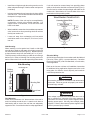
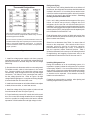
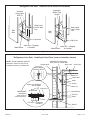
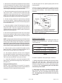
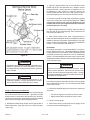
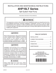
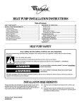
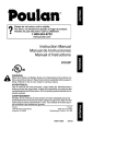
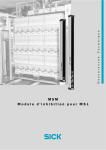
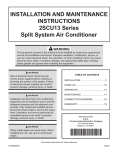
INSTALLATION AND MAINTENANCE INSTRUCTIONS
4AC18LT SERIES
Split System Air Conditioner
Save these instructions for future reference
WARNING
The equipment covered in this manual is to be installed by trained and experienced service
and installation technicians. Improper installation, modification, service, or use can cause
electrical shock, fire, explosion, or other conditions which may cause personal injury, death,
or property damage. Use appropriate safety gear including safety glasses and gloves when
installing this equipment.
WARNING
TABLE OF CONTENTS
Risk of electrical shock. Disconnect all remote power
supplies before installing or servicing any portion of the
system. Failure to disconnect power supplies can result
in property damage, personal injury, or death.
INSTALLATION .................................................... 2
START-UP .......................................................... 13
OPERATION ...................................................... 17
WARNING
MAINTENANCE ................................................. 21
Installation and servicing of air conditioning equipment
can be hazardous due to internal refrigerant pressure
and live electrical components. Only trained and
qualified service personnel should install or service this
equipment. Installation and service performed by
unqualified persons can result in property damage,
personal injury, or death.
CONNECTION DIAGRAM .................................. 23
Manufactured By
Allied Air Enterprises, Inc.
A Lennox International Inc. Company
215 Metropolitan Drive
West Columbia, SC 29170
WARNING
Sharp metal edges can cause injury. When installing
the unit, use care to avoid sharp edges.
506469-01
*506469-01*
Issue 1008
Page 1 of 24
INSTALLATION
General
Read this entire instruction manual, as well as the
instructions supplied in separate equipment, before
starting the installation. Observe and follow all
warnings, cautions, instructional labels, and tags.
Failure to comply with these instructions could result
in an unsafe condition and/or premature component
failure.
These instructions are intended as a general guide only for
use by qualified personnel and do not supersede any national
or local codes in any way. The installation must comply with
all provincial, state, and local codes as well as the National
Electrical Code (U.S.) or Canadian Electrical Code (Canada).
Compliance should be determined prior to installation.
4AC18LT condensing units use R410A which is an ozonefriendly HFC refrigerant. The unit must be installed with a
matching indoor coil and line set. 4AC18LT units are
designed for use in expansion valve (TXV) systems only. A
filter drier approved for use with R410A is installed in the
unit.
When servicing or repairing HVAC components, ensure the
fasteners are appropriately tightened. Table 1 shows torque
values for fasteners.
Inspection of Shipment
Upon receipt of equipment, carefully inspect it for possible
shipping damage. If damage is found, it should be noted on
the carrier’s freight bill. Take special care to examine the
unit inside the carton if the carton is damaged. Any concealed
damage discovered should be reported to the last carrier
immediately, preferably in writing, and should include a
request for inspection by the carrier’s agent.
If any damages are discovered and reported to the carrier
DO NOT INSTALL THE UNIT, as claim may be denied.
Check the unit rating plate to confirm specifications are
as ordered.
Location of Unit
Outdoor units operate under a wide range of weather
conditions; therefore, multiple factors must be considered
when positioning the unit. The unit must be positioned to
give adequate clearances for sufficient airflow and servicing.
Refer to Figure 1 for installation clearances.
IMPORTANT: This product has been designed and
manufactured to meet ENERGY STAR criteria for energy
efficiency when matched with appropriate coil components.
However, proper refrigerant charge and proper air flow are
critical to achieve rated capacity and efficiency. Installation
of this product should follow the manufacturer’s refrigerant
charging and air flow instructions. Failure to confirm proper
charge and airflow may reduce energy efficiency and
shorten equipment life.
Torque Table
Installation Clearances
36”
36” *
36”
36” *
Fastener
Torque
Stem Caps
8 ft. lbs.
Service Port Caps
8 ft. lbs.
Sheet Metal Screws
16 in. lbs.
#8 Machine Screws
16 in. lbs.
#10 Machine Screws
28 in. lbs.
Compressor Bolts
90 in. lbs.
* A service clearance of 30" must be maintained on one of the
sides adjacent to the control box. Clearance to one of the other
three sides must be 36". Clearance to one of the remaining two
sides may be 12" and the final side may be 6".
A clearance of 24" must be maintained between units.
48" clearance required on top of unit. Maximum soffit overhang is
36".
Figure 1
Table 1
506469-01
Issue 1008
Page 2 of 24
•
Install the unit high enough above the ground or roof to
allow adequate drainage of defrost water and prevent
ice buildup.
•
In heavy snow areas, do not locate the unit where drifting
snow will occur. The unit base should be elevated above
the depth of average snows.
If unit coil cannot be mounted away from prevailing winter
winds, a wind barrier should be constructed (See Figure 3).
Size the barrier at least the same height and width as the
outdoor unit. Mount barrier 24” from the sides of the unit in
the direction of the prevailing winds.
NOTE: Elevation of the unit may be accomplished by
construction a frame using suitable materials. If a
support frame is constructed, it must not block drain
holes in unit base.
•
When installed in areas where low ambient temperatures
exist, locate unit so winter prevailing winds do not blow
directly into outdoor coil.
•
Locate unit away from overhanging roof lines which
would allow water or ice to drop on, or in front of, coil or
into unit.
Slab Mounting
When installing a unit at grade level, install on slab high
enough above grade so that water from higher ground will
not collect around the unit (See Figure 2). Slab should have
a slope tolerance away from the building of 2° or 2” per 5’.
This will prevent ice from building up under the unit during a
defrost cycle. Refer to following roof mounting section for
barrier construction if unit must face prevailing winter winds.
Slab Mounting
Figure 3
Electrical Wiring
All field wiring must be done in accordance with the National
Electrical Code (NEC) recommendations, Canadian
Electrical Code (CEC) and CSA Standards, or local codes,
where applicable.
Refer to the furnace or blower coil installation instructions
for additional wiring application diagrams and refer to unit
rating plate for minimum circuit ampacity and maximum
overcurrent protection size.
Discharge Air
Building
Structure
WARNING
Unit must be grounded in accordance with national and
local codes. Failure to ground unit properly can result in
personal injury or death.
Mounting Slab
Ground Level
WARNING
Figure 2
Roof Mounting
Install unit at a minimum of 6” above surface of the roof to
avoid ice buildup around the unit. Locate the unit above a
load bearing wall or area of the roof that can adequately
support the unit. Consult local codes for rooftop applications.
506469-01
Issue 1008
Line voltage is present at all components when unit is
not in operation on units with single pole contactors.
Disconnect all remote electric power supplies before
opening access panel. Unit may have multiple power
supplies. Failure to disconnect all power supplies could
result in personal injury or death.
Page 3 of 24
Placement
Be aware that some localities are adopting sound ordinances
based on how noisy the unit is at the neighbor’s home, not
at the original installation. Install the unit as far as possible
from the property line. When possible, do not install the unit
directly outside a bedroom window. Glass has a verry high
level of sound transmission. Figure 5 on page 5 shows how
to place the outdoor unit and line set to reduce line set
vibration.
Line Set Isolation
Illustrations on the pages 6 and 7 demonstrate procedures
which ensure proper refrigerant line set isolation. Figure 6
shows how to install line sets on horizontal runs. Figure 7
shows how to make a transition from horizontal to vertical.
Figure 9 shows how to install line sets on vertical runs.
Refrigerant Line Set Diameters (in.)
L iquid L ine
B T UH
Brazing Connection Procedure
1. Cut ends of refrigerant lines square (free from nicks or
dents). Debur the ends. The pipe must remain round; do
not pinch end of line.
2. Before making line set connections, use dry nitrogen to
purge the refrigerant piping. This will help to prevent
oxidation and the introduction of moisture into the system.
3. Use silver alloy brazing rods (5% or 6% silver alloy for
copper-to-copper brazing or 45% silver alloy for copper-tobrass or copper-to-steel brazing) which are rated for use
with R410A refrigerant.
4. Remove the Schrader core assemblies before brazing to
protect them from damage due to extreme heat. Replace
the cores when brazing is complete.
5. Remove light maroon washers from service valves and
shield light maroon stickers to protect them during brazing.
Wrap a wet cloth around the valve body and copper tube
stub to protect it from heat damage.
L ine S e t L e ngth a nd S iz e
12 ft.
25 ft. 50 ft. 75 ft. 100 ft.
24,000
3/8
3/8
3/8
3/8
3/8
36,000
3/8
3/8
3/8
3/8
1/2
48,000
3/8
3/8
3/8
1/2
1/2
60,000
3/8
3/8
3/8
1/2
1/2
Outside Unit Placement & Installation
Install unit away
from windows
S uction L ine
L ine S e t L e ngth a nd S iz e
B T UH
12 ft.
25 ft.
50 ft.
75 ft. 100 ft.
24,000
3/4
3/4
3/4
3/4
7/8
36,000
7/8
7/8
7/8
7/8
1-1/8
48,000
7/8
1-1/8
1-1/8
1-1/8
1-1/8
60,000 1-1/8
1-1/8
1-1/8
1-1/8
1-1/8
Two 90° elbows installed in lineset
will reduce lineset vibration
Figure 5
For installations exceeding 50’, contact
Technical Services.
Table 2
506469-01
Issue 1008
Page 5 of 24
Refrigerant Piping
If the 4AC18LT unit is being installed with a new indoor coil
and line set, the refrigerant connections should be made as
outlined in this section. If an existing line set and/or indoor
coil will be used to complete the system, refer to this section
as well as the section that follows entitled - Flushing
Existing Line Set and Indoor Coil.
Thermostat Designations
If this unit is being matched with an approved line set or
indoor coil which was previously charged with R-22
refrigerant, the line set and coil must be flushed prior to
installation. If the unit is being used with and existing indoor
coil which was equipped with a liquid line which served as a
metering device (RFCI), the liquid line must be replaced prior
to the installation of the 4AC18LT unit.
See unit wiring diagram for power supply connections.
If the indoor unit is not equipped with a blower relay, one must
be field supplied and installed.
Do not connect C (common) connection between indoor unit
and thermostat except when required by the indoor thermostat.
Refer to thermostat installation instructions. C (common)
connection between indoor unit and outdoor unit required for
proper operation.
Figure 4
1. Install line voltage power supply to unit from a properly
sized disconnect switch. Any excess high voltage field wiring
should be trimmed or secured away from the low voltage
field wiring.
2. Ground unit at unit disconnect switch or to an earth ground.
To facilitate conduit, a hole is in the bottom of the control
box. Connect conduit to the control box using a proper
conduit fitting. Units are approved for use only with copper
conductors. 24V Class II circuit connections are made in
the low voltage junction box. Refer to Figure 4 for high
voltage field wiring diagram. A complete unit wiring diagram
is located inside the unit control box cover.
Field refrigerant piping consists of liquid and suction lines
from the outdoor unit (sweat connections) to the indoor coil
(flare or sweat connections).
Select line set diameters from Table 2 to ensure that oil
returns to the compressor. Size vertical suction riser to
maintain minimum velocity at minimum capacity.
Recommended line length is 50’ or less. If more than 50’
line set is required, contact Technical Services. Table 2
shows the diameters for line sets up to 100’ although vertical
lift applications and trapping requirements need to be
reviewed with Technical Services for line sets over 50’.
Installing Refrigerant Line
During the installation of an air conditioning system, it is
important to properly isolate the refrigerant line to prevent
unnecessary vibration. Line set contact with the structure
(wall, ceiling, or floor) may cause objectionable noise when
vibration is translated into sound. As a result, more energy
or vibration can be expected. Close attention to line set
isolation must be observed.
Following are some points to consider when placing and
installing a high-efficiency outdoor unit:
3. Install room thermostat on an inside wall that is not subject
to drafts, direct sunshine, or other heat sources.
4. Install low voltage wiring from outdoor to indoor unit and
from thermostat to indoor unit (See Figure 5).
5. Do not bundle any excess 24V control wire inside control
box. Run control wire through installed wire tie and tighten
wire tie to provide low voltage strain relief and to maintain
seperation of field-installed low and high voltage circuits.
506469-01
Issue 1008
Page 4 of 24
6. Braze the line set to the service valve. Quench the joints
with water or a wet cloth to prevent heat damage to the
valve core and opening port. The tube end must stay
bottomed in the fitting during final assembly to ensure
proper seating, sealing, and rigidity.
7. Install the thermal expansion valve which is sold
separately and which is approved for use with R410A
refrigerant in the liquid line at the indoor coil (see Refrigerant
Metering Device on page 9).
CAUTION
When flushing existing line set and/or indoor coil, be sure to
empty all existing traps. Residual mineral oil can act as an
insulator, preventing proper heat transfer. It can also clog
the thermal expansion valve, reducing system performance
and capacity. Failure to properly flush system as explained
in these instructions will void warranty.
Refrigerant Line Sets: Installing Horizontal Runs
To hang line set from joist or rafter,
use either metal strapping material
or anchored heavy nylon wire ties.
Wire Tie
(around vapor line only)
8’
Strapping Material
(around vapor line only)
Floor Joist or
Roof Rafter
Tape or Wire Tie
8’
Strap the vapor line to the joist or rafter
at 8’ intervals then strap the liquid line
to the vapor line.
Metal Sleeve
Floor Joist or Roof Rafter
Tape or Wire Tie
Figure 6
506469-01
Issue 1008
Page 6 of 24
Refrigerant Line Sets: Transition from Vertical to Horizontal
Automotive
Muffler-Type
Hanger
Anchored
Heavy Nylon
Wire Tie
Strap Liquid
Line to Vapor
Line
Wall
Stud
Strap Liquid
Line to Vapor
Line
Wall
Stud
Liquid Line
Metal Sleeve
Liquid Line
Vapor Line – Wrapped
in Armaflex
Metal Sleeve
Vapor Line – Wrapped
in Armaflex
Figure 7
Refrigeraant Line Sets: Installing Vertical Runs (new construction shown)
IMPORTANT: Refrigerant
lines must not contact wall.
NOTE: Similar installation practices
should be used if line set is to be
installed on exterior of outside wall.
Outside Wall
Vapor Line
Liquid Line
Wood Block
Between Studs
Wire Tie
Inside Wall
Strap
Sleeve
Vapor Line Wrapped
with Armaflex
Wire Tie
Liquid Line
IMPORTANT:
Refrigerant
lines must not
contact structure.
Outside Wall
Wood Block
Wire Tie
Strap
Caulk
PVC Pipe
Fiberglass
Insulation
Sleeve
Figure 8
506469-01
Issue 1008
Page 7 of 24
Flushing Existing Line Set and Indoor Coil
This procedure should not be performed on systems
which contain contaminants, such as compressor burn
out.
Required Euipment
The following equipment is needed to flush the existing line
set and indoor coil (See Figure 9). Two clean R-22 recovery
bottles, an oil-less recovery machine with a “pump down”
feature, and two sets of gauges (one for use with R-22 and
one for use with R410A).
Flushing Procedure
IMPORTANT: The line set and/or indoor coil must be
flushed with at least the same amount of refrigerant that
previously charged the system. Check the charge in the
flushing cylinder before flushing the unit.
1. Remove existing R-22 refrigerant using the appropriate
procedure.
If the existing outdoor unit is not equipped with shutoff valves,
or if the unit is not operational AND the existing R-22
refrigerant will be used to flush the system:
Disconnect all power to the existing outdoor unit. Connect
the existing unit, a clean recovery cylinder, and the recovery
machine according to the instructions provided with the
recovery machine. Remove all R-22 refrigerant from the
existing system. Refer to the gauges after shutdown to
confirm that the entire system is completely void of
refrigerant. Disconnect the liquid and suction lines from the
existing outdoor unit.
If the existing outdoor unit is equipped with manual shutoff
valves AND new R-22 refrigerant will be used to flush the
system:
Start the existing R-22 refrigerant system in cooling mode
and close the liquid line valve. Pump all the existing R-22
refrigerant back into the outdoor unit.
(It may be necessary to bypass the low pressure switches
to ensure complete refrigerant evacuation.)
When the low side system pressures reach 0 psig, close
the suction line valve. Disconnect all power to the existing
outdoor unit. Refer to the gauges after shutdown to confirm
that the valves are not allowing refrigerant to flow back into
the low side of the system. Disconnect the liquid and suction
lines from the existing outdoor unit.
2. Remove the existing outdoor unit. Set the new R410A
unit and follow the brazing connection procedure outlined
previously on this page to make line set connections. Do
not install the R410A thermal expansion valve at this
time.
3. Make low voltage and line voltage connections to the
new outdoor unit. Do not turn on power to the unit or
open the outdoor unit service valves at this time.
Flushing Connections
Figure 9
506469-01
Issue 1008
Page 8 of 24
4. Remover the existing R-22 refrigerant flow control orifice
or thermal expansion valve before continuing with flushing
procedures. R-22 flow control devices are not approved for
use with R410A refrigerant and may prevent proper flushing.
Use a field-provided fitting to reconnect the lines.
5. Remove the pressure tap valve cores from the 4AC18LT
units service valves. Connect an R-22 cylinder with clean
refrigerant to the suction service valve. Connect the R-22
gauge set to the liquid line valve and connect a recovery
maching with an empty recovery tank to the gauge set.
An R410A system will not operate properly with an R-22
metering device.
Install the refrigerant metering device as shown in Figure
10. Do not twist cap tubes when loosening the seal nut
from the orifice housing. Use wrench to back up the
distributor.
6. Set the recovery machine for liquid recovery and start
the recovery machine. Open the gauge set valves to allow
the recovery machine to pull a vacuum on the existing system
line set and indoor coil.
7. Invert the cylinder of clean R-22 and open its valve to
allow liquid refrigerant to flow in to the system through the
suction line valve. Allow the refrigerant to pass from the
cylinder and through the line set and the indoor coil before it
enters the recovery machine.
8. After all of the liquid refrigerant has been recovered, switch
the recovery machine to vapor recovery so that all of the R22 vapor is recovered. Allow the recovery machine to pull a
vacuum on the sytem.
NOTE: A single system flush should remove all of the mineral
oil from the existing refrigerant lines and indoor coil. A second
flushing may be done (using clean refrigerant) if insufficient
amounts of mineral oil were removed during the first flush.
After each system flush, allow the recovery machine to
pull a vacuum on the system at the end of the procedure.
Figure 10
Expansion Valve Systems
Expansion valves equipped with Chatleff-type fittings are
available from the manufacturer. See Table 4 for proper
TXV for each unit.
TXV Data
9. Close the valve on the inverted R-22 cylinder and the
gauge set valves. Pump the remaining refrigerant out of
the recovery machine and turn the machine off.
10. Use nitrogen to break the vacuum on the refrigerant
lines and indoor coil before removing the recovery machine,
gauges, and R-22 refrigerant drum. Re-install pressure tap
valve cores into the 4AC18LT unit’s service valves.
11. Install the fixed orifice (or thermal expansion valve
approved for use with R410A refrigerant) in the liquid line at
the indoor coil.
Refrigerant Metering Device
4AC18LT units are designed for use with TXV systems.
Refer to the appropriate following section for information on
installing the chosen refrigerant metering device.
506469-01
MODEL
PART NUMBER
4AC18LT- 24, -36
4AC18LT - 48, -60
H4TXV01
H4TXV03
Table 4
To install an expansion valve (See Figure 10 above):
1. Separate the distributor assembly and remove the piston
orifice and used teflon seal. Insert nozzle end of the
expansion valve along with a new teflon seal into the
distributor and tighten to 20 - 30 ft. lbs. Use backup wrench
on all wrench flats. Overtightening will crush the teflon
seal and may cause a leak.
2. Attach liquid line portion of distributor assembly along
with new teflon seal to the inlet of the expansion valve.
Tighten to 20 - 30 ft. lbs. Use backup wrench on all wrench
flats. Overtightening will crush the teflon seal and may
cause a leak.
Issue 1008
Page 9 of 24
3. Connect the external equalizer line to the equalizer port
on the suction line and tighten to 8 ft.lbs.
4. Strap the superheat sensing bulb to the suction header.
If installing an expansion valve on an indoor coil that
previously used a fixed orifice, be sure to remove the existing
fixed orifice. Failure to remove a fixed orifice when installing
an expansion valve to the indoor coil will result in improper
operation and damage to the system.
Manifold Gauge Set
Manifold guage sets used with systems charged with R410A
refrigerant must be capable of handling the higher system
operating pressures. The gauges should be rated for use
with pressures 1 - 800 on the high side and a low side of 30”
vacuum to 250 psi with dampened speed to 500 psi. Gauge
hoses must be rated for use at up to 800 psi of pressure
with a 4000 psi burst rating.
Suction Line (Ball Type) Service Valve
Suction line (ball type) service valves function the same way
as the other valves; the difference is in the construction (See
Figure 12).
The ball valve is equipped with a service port with a factoryinstalled Schrader valve. A service port cap protects the
Schrader valve from contamination and serves as the
primary seal.
Leak Testing
After the line set has been connected to the indoor and
outdoor units, the line set connections and indoor unit must
be checked for leaks.
Liquid and Suction Line Service Valves
The liquid line and suction line service valves (See Figure
11) and service ports are used for leak teating, evacuation,
charging, and checking charge.
Each valve is equipped with a service port which has a
factory-installed Schrader valve. A service port cap protects
the Schrader valve from contamination and serves as the
primary leak seal.
To Access the Schrader Port:
1. Remove the service port cap with an adjustable wrench.
2. Connect gauge to the service port.
3. When testing is completed, replace service port cap.
Tighten finger tight, then an additional 1/6 turn.
To Open Liquid or Suction Line Service Valve:
Remove stem cap with an adjustable wrench.
Use service wrench with a hex-head extension to back the
stem out counterclockwise as far as it will go. Use a 3/16”
hex head extension for liquid line service valves and a 5/
16” extension for suction line service valves.
Replace the stem cap. Tighten finger tight, then tighten an
additional 1/6 turn.
To Close Liquid or Suction Line Service Valve:
1. Remove the stem cap with an adjustable wrench.
Figure 11
2. Use a service wrench with a hex-head extension to turn
the stem clockwise to seat the valve. Tighten firmly.
3. Replace the stem cap. Tighten finger tight, then tighten
an additional 1/6 turn.
506469-01
Issue 1008
Page 10 of 24
3. Open the high pressure side of the manifold to allow
R410A into the line set and indoor unit. Weigh in a trace
amount of R410A. (A trace amount is a maximum of 2 oz.
of refrigerant or 3 lbs. pressure.) Close the valve on the
R410A cylinder and the valve on the high pressure side of
the manifold gauge set. Disconnect the R410A cylinder.
4. Connect a cylinder of nitrogen with a pressure regulating
valve to the center port of the manifold gauge set. When
using high pressure gas such as nitrogen for this
purpose, be sure to use a regulator that can control the
pressure down to 1 or 2 psig.
5. Adjust nitrogen pressure to 150 psig. Open the valve on
the high side of the manifold gauge set to pressurize the
line set and the indoor coil.
6. After a short period of time, open a refrigerant port to
make sure that an adequate amount of refrigerant has been
added for detection (refrigerant requirements will vary with
lenths). Check all joints for leaks. Purge nitrogen and R410A
mixture. Correct any leaks and rechecks.
Evacuation
Evacuating the system of noncondensables is critical for
proper operation of the unit. Noncondensables are defined
as any gas that will not condense under temperatures and
pressures present during operation of an air conditioning
system. Noncondensables and water vapor combine with
refrigerant to produce substances that corrode copper piping
and compressor parts.
Figure 12
WARNING
Refrigerant can be harmful if inhaled. Refrigerant must
always be used and recovered responsibly. Incorrect
or irresponsible use of refrigerant can result in personal
injury or death.
WARNING
Do Not use a compressor to evacuate a system. Avoid
deep vacuum operation. Extremely low vacuums can
cause internal arcing and compressor failure. Danger
of equipment damage. Damage caused by deep vacuum
operation will void warranty.
WARNING
Never use oxygen to pressurize refrigeration or air
conditioning systems. Oxygen will explode on contact
with oil and could cause personal injury or death.
Use a thermocouple or thermistor electronic vacuum gauge
that is calibrated in microns. Use an instrument that reads
down to 50 microns.
Using an Electronic Leak Detector
1. Connect the high pressure hose of the manifold gauge
set to the suction valve service port. (Normally the high
pressure hose is connected to the liquid line port; however,
connecting it to the suction ports helps to protect the manifold
gauge set from damage caused by high pressure.)
2. With both manifold valves closed, connect the cylinder of
R410A refrigerant. Open the valve on the R410A cylinder
(vapor only).
506469-01
1. Connect the manifold gauge set to the service valve ports
as follows:
• Low pressure gauge to suction line service valve
• High pressure gauge to liquid line service valve.
2. Connect micron gauge.
3. Connect the vacuum pump (with vacuum gauge) to the
center port of the manifold gauge set.
Issue 1008
Page 11 of 24
4. Open both manifold valves and start vacuum pump.
5. Evacuate the line set and indoor unit to a minimum of
500 microns or lower. During the early stages of evacuation,
it is desirable to close the manifold gauge valve at least once
to determine if there is a rapid rise in pressure. A rapid rise
in pressure indicates a relatively large leak. If this occurs,
the leak testing procedure must be repeated.
6. When 500 microns or lower is maintained, close the
manifold gauge valves, turn off the vacuum pump, and
disconnect the manifold gauge center port hose from the
vacuum pump. Attach the manifold gauge center port hose
to a nitrogen cylinder with pressure regulator set to 150 psig
and purge the hose. Open the manifold gauge valves to
break the vacuum in the line set and indoor unit. Close the
manifold gauge valves.
7. Shut off the nitrogen cylinder and remove the manifold
gauge hose from the cylinder. Open the manifold gauge
valves to release the nitrogen from the line set and indoor
unit.
8. Reconnect the manifold gauge to the vacuum pump,
turn the pump on, and continue to evacuate the line set and
indoor unit until 500 microns is maintained within a 20 minute
period after shutting off the vacuum pump and closing the
manifold gauge valves.
9. When the requirements above have been met, disconnect
the manifold hose from the vacuum pump. Open the service
valves to break the vacuum in the line set and indoor unit.
506469-01
Issue 1008
Page 12 of 24
START-UP
Units are factory charged with the amount of R410A
refrigerant indicated on the unit rating plate. This charge is
based on a matching indoor coil and outdoor coil with 15’
line set. For varying lengths of line set, refer to Table 5 for
refrigerant charge adjustment. A blank space is provided
on the unit rating plate to list the actual field charge.
CAUTION
If unit is equipped with a crankcase heater, it should be
energized 24 hours before unit start-up to prevent
compressor damage as a result of slugging.
Refrigerant Charge Adjustment
1. Rotate fan to check for frozen bearings or binding.
Liquid Line Set
Diameter
2. Inspect all factory and field-installed wiring for loose
connections.
* If line length is greater than 15 ft., add this amount.
If line length is less than 15 ft., remove this amount.
Table 5
4. Replace the stem caps and secure finger tight, then
tighten an additional 1/6 of a turn.
6. Set thermostat for cooling demand, turn on power to
indoor blower, and close the outdoor unit disconnect switch
to start the unit.
7. Recheck unit voltage with unit running. Power must be
within range shown on unit nameplate.
3 oz. Per 5 ft.
3/8 in.
3. After evacuation is complete, open liquid line and suction
line service valves to release refrigerant charge (contained
in outdoor unit) into system.
5. Check voltage supply at the disconnect switch. The
voltage must be within the range listed on the unit nameplate.
If not, do not start equipment until the power company has
been consulted and the voltage condition corrected.
Oz. per 5 ft. adjust
from 15 ft. line set*
IMPORTANT
Mineral oils are not compatible with R410A. If oil must
be added, it must be a polyolester oil.
If the system is void of refrigerant, clean the system using
the procedure described below.
1. Use dry nitrogen to pressurized the system and check
for leaks. Repair leaks, if possible.
2. Evacuate the system to remove as much of the moisture
as possible.
3. Use dry nitrogen to break the vacuum.
Refrigerant Charging
This system is charged with R410A refrigerant which
operates at much higher pressures than R-22. The liquid
line drier provided with the unit is approved for use with
R410A. Do not replace it with one designed for use with R22. This unit is NOT approved for use with coils which
use capillary tubes as a refrigerant metering device.
R410A refrigerant cylinders are rose colored. Refrigerant
should be added through the suction valve in the liquid state.
Certain R410A cylinders are identified as being equipped
with a dip tube. These allow liquid refrigerant to be drawn
from the bottom of the cylinder without inverting the cylinder.
Do not turn this type of cylinder upside down to draw
refrigerant.
4. Evacuate the system again.
5. Weigh the appropriate amount of R410A refrigerant (listed
on unit nameplate) into the system.
6. Monitor the system to determine the amount of moisture
remaining in the oil. Use a test kit to verify that the moisture
content is withing the kit’s dry color range. It may be
necessary to replace the filter drier several times to achieve
the required dryness level. If system dryness is not
verified, the compressor will fail in the future.
The outdoor unit should be charged during warm weather.
However, applications arise in which charging must occur in
the colder months. The method of charging is determined
by the unit’s refrigerant metering device and the outdoor
ambient temperature.
Measure the liquid line temperature and the outdoor ambient
temperature as outlined below:
506469-01
Issue 1008
Page 13 of 24
1. Connect the manifold gauge set to the service valve ports
as follows (See Figure 13):
Blocking Outdoor Coil
Outdoor coil should be
blocked one side at a time
with cardboard or plastic
sheet until proper testing
pressures are reached
• Low pressure gauge to suction line service valve
• High pressure gauge to liquid line service valve
2. Close manifold gauge set valves. Connect the center
manifold hose to an upright cylinder of R410A.
CARDBOARD OR
PLASTIC SHEET
3. If room temperature is below 70°F, set the room
thermostat to call for heat. This will create the necessary
load for properly charging the system in the cooling cycle.
Figure 11
4. Use a digital thermometer to record the outdoor ambient
temperature.
_
5. When the heating demand has been satisfied, switch the
thermostat to cooling mode with a set point of 68°F. When
pressures have stabilized, use a digital thermometer to
record the liquid and suction line temperatures.
6. The outdoor temperature will determine which charging
method to use. Proceed with the appropriate charging
method.
Charge Using Subcooling Method - Outdoor
Temperatures Below 65°F
When the outdoor ambient temperature is below 65°F, the
subcooling method can be used to charge the unit. It may
be necessary to restrict the air flow through the outdoor coil
to achieve pressures in the 200-250 psig range. These
higher pressures are necessary for checking the charge.
Block equal sections of air intake panels and move
obstructions sideways until the liquid pressure is in the 200250 psig range (see Figure 11).
1. With the manifold gauge hose on the liquid service port
and the unit operating stably, use a digital thermometer to
record the liquid line temperature.
2. At the same time, record the liquid line pressure reading.
3. Use the temperature/pressure chart (Table 5 on page
14) to determine the saturation temperature for the liquid
line pressure reading.
4. Subtract the liquid line temperature from the saturation
temperature (according to the chart) to determine subcooling
=
Saturation Tempera
°
°
Liquid Line Tempera
Subcooling Value °F
5. Compare the subcooling value with those shown in Table
6 on page 14. If subcooling is greater than shown, recover
some refrigerant. If subcooling is less than shown, add some
refrigerant.
Charge Using Approach Method - Outdoor Temperatures
65°F or Above
The following procedure is intended as a general guide and
is for use on expansion valve systems only. For best results,
indoor temperature should be 70°F to 80°F. Monitor system
pressures while charging.
1. Record outdoor ambient temperature using a digital
thermometer.
2. Attach high pressure gauge set and operate unit for
several minutes to allow system pressures to stabilize.
3. Compare stabilized pressures with those provided in Table
8 on page 15. Minor variations in these pressures may be
expected due to differences in installations. Significant
differences could mean that the system is not properly
charged or that a problem exists with some component
in the system. Pressures higher than those listed indicate
that the system is undercharged. Verify adjusted charge
using the approach method.
4. Use the same digital thermometer to check liquid line
temperature.
5. Subtract the outdoor ambient temperature from the liquid
line temperature to determine the approach temperature.
506469-01
Issue 1008
Page 14 of 24
Subcooling Values
R410A Temperature/Pressure Chart
Temp.
(F
P re s s u re
P s ig
Temp.
(F
P re s s u re
P s ig
Temp.
(F
P re s s u re
P s ig
32
1 0 0 .8
74
2 1 4 .0
116
3 9 6 .0
33
1 0 2 .9
75
2 1 7 .4
117
4 0 1 .3
34
1 0 5 .0
76
2 2 0 .9
118
4 0 6 .7
35
1 0 7 .1
77
2 2 4 .4
119
4 1 2 .2
36
1 0 9 .2
78
2 2 8 .0
120
4 1 7 .7
37
1 1 1 .4
79
2 3 1 .6
121
4 2 3 .2
38
1 1 3 .6
80
2 3 5 .3
122
4 2 8 .8
39
1 1 5 .8
81
2 3 9 .0
123
4 3 4 .5
40
1 1 8 .0
82
2 4 2 .7
124
4 4 0 .2
41
1 2 0 .3
83
2 4 6 .5
125
4 4 5 .9
42
1 2 2 .6
84
2 5 0 .3
126
4 5 1 .8
43
1 2 5 .0
85
2 5 4 .1
127
4 5 7 .6
44
1 2 7 .3
86
2 5 8 .0
128
4 6 3 .5
45
1 2 9 .7
87
2 6 2 .0
129
4 6 9 .5
46
1 3 2 .2
88
2 6 6 .0
130
4 7 5 .6
47
1 3 4 .6
89
2 7 0 .0
131
4 8 1 .6
48
1 3 7 .1
90
2 7 4 .1
132
4 8 7 .8
49
1 3 9 .6
91
2 7 8 .2
133
4 9 4 .0
50
1 4 2 .2
92
2 8 2 .3
134
5 0 0 .2
51
1 4 4 .8
93
2 8 6 .5
135
5 0 6 .5
52
1 4 7 .4
94
2 9 0 .3
136
5 1 2 .9
53
1 5 0 .1
95
2 9 5 .1
137
5 1 9 .3
54
1 5 2 .8
96
2 9 9 .4
138
5 2 5 .8
55
1 5 5 .5
97
3 0 3 .8
139
5 3 2 .4
56
1 5 8 .2
98
3 0 8 .2
140
5 3 9 .0
57
1 6 1 .0
99
3 1 2 .7
141
5 4 5 .6
58
1 6 3 .9
100
3 1 7 .2
142
5 5 2 .3
59
1 6 6 .7
101
3 2 1 .8
143
5 5 9 .1
60
1 6 9 .6
102
3 2 6 .4
144
5 6 5 .9
61
1 7 2 .6
103
3 3 1 .0
145
5 7 2 .8
62
1 7 5 .5
104
3 3 5 .7
146
5 7 9 .8
63
1 7 8 .5
105
3 4 0 .5
147
5 8 6 .8
64
1 8 1 .6
106
3 4 5 .3
148
5 9 3 .8
65
1 8 4 .3
107
3 5 0 .1
149
6 0 1 .0
66
1 8 7 .7
108
3 5 5 .0
150
6 0 8 .1
67
1 9 0 .9
109
3 6 0 .0
151
6 1 5 .4
68
1 9 4 .1
110
3 6 5 .0
152
6 2 2 .7
69
1 9 7 .3
111
3 7 0 .0
153
6 3 0 .1
70
2 0 0 .6
112
3 7 5 .1
154
6 3 7 .5
71
2 0 3 .9
113
3 8 0 .2
155
6 4 5 .0
72
2 0 7 .2
114
3 8 5 .4
73
2 1 0 .6
115
3 9 0 .7
72
2 0 7 .2
114
3 8 5 .4
73
2 1 0 .6
115
3 9 0 .7
Table 7
° Saturation Temperature °F
_
° Liquid Line Temperature °F
=
°
Subcooling Value °F
6. Compare the approach value with those shown in Table
7. If the values do not agree with those provided in Table 7,
add refrigerant to lower the approach temperature or recover
refrigerant from the system to increase the approach
temperature.
Approach Values for TXV Systems
Approach value is the liquid line temperature minus
the outdoor ambient temperature (± 1°F).
Note: For best results, use the same digital
thermometer to check both outdoor ambient and
liquid temperatures.
Table 8
Check Charge Using Normal Operating Pressures
Use Table 8 to perform maintenance checks. Table 8 is not
a procedure for charging the system. Minor variations in
these pressures may be due to differences in installations.
Significant deviations could mean that the system is not
properly charged or that a problem exists with some
component in the system.
_
=
° Liquid Line Temperature °F
° Outdoor Ambient Temperature °F
°
Approach Temperature °F
Table 6
506469-01
Issue 1008
Page 15 of 24
Table 8
506469-01
Issue 1008
Page 16 of 24
OPERATION
Outdoor unit and indoor blower cycle on demand from the
room thermostat. When the thermostat blower switch is
moved to the ON position, the indoor blower operates
continuously.
System Diagnostic Module
4AC18LT units contain a diagnostic module for
troubleshooting air conditioning system failures. By
monitoring and analyzing data from the compressor and
thermostat demand, the module can accurately detect the
cause of electrical and system related failure without any
sensors. If a system problem occurs, a flashing LED
indicator communicates the failure code.
LED Description
POWER LED (Green) indicates voltage is present at the
power connection of the module.
Thermostat Demand Wiring
The diagnostic module requires a thermostat demand signal
to operate properly. The thermostat demand signal input,
labeled Y on the module, should always be connected to
the compressor contactor coil so that when the coil is
energized, the demand signal input is 24VAC. When the
Coil is not energized, the demand signal input should be
less than 0.5VAC.
Miswired Module Codes
Depending on the system configuration, some ALERT flash
codes may not be active. The presence of safety switches
affects how the system alerts are displayed by the module.
Miswiring the diagnostic module will cause false LED codes.
Table 11 on page 19 describes LED opeation when the
module is miswired and what troubleshooting action is
required to correct the problem.
ALERT LET (Yellow) communicates an abnormal system
condition through a unique flash code. The ALERT LED will
flash a number of times consecutively, pause, and then
repeat the process. The number of consecutive flashes
correlates to a particular abnormal condition.
TRIP LED (Red) indicates there is a demand signal from
the thermostat but no current to the compressor is detected
by the module. The TRIP LED typically indicates the
compressor protector is open or may indicate missing supply
power to the compressor.
Interpreting the Diagnostic LEDs
When an abnormal system condition occurs, the diagnostic
module displays the appropriate ALERT and/or TRIP LED.
The yellow ALERT LED will flash a number of times
consecutively, pause, and then repeat the process. To
identify a flash code number, count the number of
consecutive flashes. Refer to Table 9 on page 18 and Table
10 on page 19 for information on the flash codes.
Every time the module powers up, the last ALERT LED flash
code that occurred prior to shutdown is displayed for 60
seconds. The module will continue to display the previous
flash code until the condition returns to normal or 24 VAC is
removed from the module. TRIP and ALERT LEDs flashing
at the same time means control circuit voltage is too low for
operation.
24 VAC Power Wiring
The diagnoctic module requires a constant nominal 24VAC
power supply. The wiring to the module’s R and C terminals
must be directly from the indoor unit or thermostat.
506469-01
Issue 1008
Page 17 of 24
Flash Codes
Table 9
506469-01
Issue 1008
Page 18 of 24
Flash Codes (cont.)
Table 10
506469-01
Issue 1008
Page 19 of 24
Miswired Module Troubleshooting
Table 11
506469-01
Issue 1008
Page 20 of 24
MAINTENANCE
4. Check all wiring for loose connections.
5. Check for correct voltage at unit (with unit operating).
WARNING
6. Check amp-draw on belower motor.
Unit nameplate_____________ Actual _________
Before performing maintenance operations on system,
turn the electric power to unit OFF at disconnect
switch(es). Unit may have multiple power supplies.
Electrical shock could cause personal injury or death.
Maintenance and service must be performed by a qualified
installer or service agency.
At the beginning of each cooling season, the system should
be checked as follows:
1. Clean and inspect condenser coil. Coil may be flushed
witha a water hose. Be sure the power is off before usig
water to clean the coil.
2. Outdoor fan motor is pre-lubricated and sealed. No further
lubrication is needed.
3. Visually inspect connecting lines and coils for evidence
of oil leaks.
4. Check wiring for loose connections.
5. Check for correct voltage at unit (with unit operating).
6. Check amp-draw outdoor fan motor.
Unit nameplate ____________ Actual __________
NOTE: If owner complains of insufficient cooling, the
unit should be gauged and refrigerant charge checked. Refer
to the Refrigerant Charging section on page 12.
Indoor Coil
1. Clean coil, if necessary.
2. Check connecting lines and coils for evidence of oil leaks.
3. Check condensate pan line and clean, if necessary.
Indoor Unit
1. Clean or change filters.
2. Adjust blower speed for cooling. Measure the pressure
drop over the coil to determine the correct blower CFM.
3. Belt drive blowers: Check belt for wear and proper
tension.
506469-01
Issue 1008
Page 21 of 24
Start-Up and Performance Checklist
Job Name _____________________________
Job No. ____________
Date ___________
Job Location ___________________________
City _______________
State ___________
Installer _______________________________
City _______________
State ___________
Unit Model No. _________________________
Serial No._____________________________
Service Technician _______________________
Nameplate Voltage _____________________
Rated Load Ampacity _________
Compressor Amperage ________
Outdoor Fan __________
Maximum Fuse or Circuit Breaker ________________________
Electical Connections Tight?
Indoor Filter Clean?
Indoor Blower RPM ___________________
Supply Voltage (Unit Off) __________
S.P. Drop Over Indoor (Dry) ____________________
Outdoor Coil Entering Air Temperature ________
Voltage with Compressor Operating __________
Discharge Pressure __________________ Vapor Pressure ____________
Refrigerant Charge Checked?
Outdoor Fan Checked?
Refrigerant Lines: Leak Checked?
Service Valves: Fully Opened?
Thermostat: Calibrated?
506469-01
Properly Insulated?
Caps Tight?
Properly Set?
Level?
Issue 1008
Page 22 of 24
WIRE DIAGRAM
506469-01
Issue 1008
Page 23 of 24
NOTES
506469-01
Issue 1008
Page 24 of 24