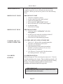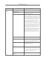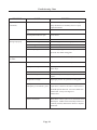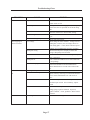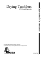
1
Operation/Maintenance
Drying Tumblers
175 Pound Capacity
Keep These Instructions for Future Reference.
(If this machine changes ownership, this manual must accompany machine.)
Part No. D0873
November 2007
Addendum A
Information in this manual is applicable to these models:
HD175
D0873
i
IMPORTANT NOTICES—PLEASE READ
For optimum efficiency and safety, we recommend that you read the manual before operating the equipment. Store this manual in a
file or binder and keep for future reference.
WARNING: For your safety, the information in this manual must be followed to minimize
the risk of fire or explosion or to prevent property damage, personal injury or loss of life.
- Do not store or use gasoline or other flammable vapors or liquids in the vicinity of this or
any other appliance.
- WHAT TO DO IF YOU SMELL GAS
•
Do not try to light any appliance.
•
•
Do not touch any electrical switch; do not use any phone in your building.
Clear the room, building or area of all occupants.
•
Immediately call your gas supplier from a neighbor's phone. Follow the gas supplier's
instructions.
•
If you cannot reach your gas supplier, call the fire department.
Installation and service must be performed by a qualified installer, service agency or the gas
supplier.
WARNING: In the event the user smells gas odor, instructions on what to do must be posted in a
prominent location. This information can be obtained from the local gas supplier.
WARNING: Wear safety shoes to prevent injuries.
WARNING: Purchaser must post the following notice in a prominent location:
FOR YOUR SAFETY
Do not store or use gasoline or other flammable vapors
and liquids in the vicinity of this or any other appliance.
WARNING: A clothes dryer produces combustible lint and should be exhausted outside the
building. The dryer and the area around the dryer should be kept free of lint.
WARNING: Be safe, before servicing machine, the main power should be shut off.
Page 1
WARNING: To avoid fire hazard, do not dry articles containing foam rubber or similar texture materials.
Do not put into this dryer flammable items such as baby bed mattresses, throw rugs,undergarments
(brassieres, etc.) and other items which use rubber as padding or backing. Rubber easily oxidizes causing
excessive heat and possible fire. These items should be air dried.
WARNING: Synthetic solvent fumes from drycleaning machines create acids when drawn through the
dryer. These fumes cause rusting of painted parts, pitting of bright or plated parts, and completely
removes the zinc from galvanized parts, such as the tumbler basket. If drycleaning machines are in the
same area as the tumbler, the tumbler's make-up air must come from a source free of solvent fumes.
WARNING: Do not operate without guards in place.
WARNING: Check the lint trap often and clean as needed but at least a minimum of once per day.
WARNING: Alterations to equipment may not be carried out without consulting with the factory and
only by a qualified engineer or technician. Only Manufacturer parts may be used.
WARNING: Remove clothes from dryer as soon as it stops. This keeps wrinkles from setting in and
reduces the possibility of spontaneous combustion.
WARNING: Be safe - shut main electrical power and gas supply off externally before attempting
service.
WARNING: Never use drycleaning solvents, gasoline, kerosene, or other flammable liquids in the dryer.
FIRE AND EXPLOSION WILL OCCUR. NEVER PUT FABRICS TREATED WITH THESE LIQUIDS
INTO THE DRYER. NEVER USE THESE LIQUIDS NEAR THE DRYER..
WARNING: Do not place items exposed to cooking oils in your dryer. Items contaminated with cooking
oils may contribute to a chemical reaction that could cause a load to catch fire.
WARNING: Never let children play near or operate the dryer. Serious injury could occur if a child
should crawl inside and the dryer is turned on.
WARNING: Never tumble fiberglass materials in the dryer unless the labels say they are machine
dryable. Glass fibers break and can remain in the dryer. These fibers cause skin irritation if they
become mixed with other fabrics.
WARNING: Before operating gas ignition system - purge air from natural gas or propane gas lines
per manufacturer’s instructions.
WARNING: To reduce the risk of electric shock, disconnect this appliance from the power supply
before attempting any user maintenance other than cleaning the lint trap. Turning the controls to the
OFF position does not disconnect this appliance from the power supply.
Page 2
ATTENTION: L’ACHETEUR DOIT PLACER L’AVERTISSEMENT
SUIVANT DANS UN ENDROIT CLAIR ET VISIBLE:
AVERTISSEMENT. Assurez-vous de bien
suivre les instructions donnees dans cette
notice pour reduire au minimum le risque
d’incendie ou d’explosion ou pour eviter tuot
dommage materiel, toute blessure ou la mort.
__ Ne pas entreposer ni utiliser d’essence ni
d’autres vapeurs ou liquides inflammables dans
le voisinage de cet appareil ou de tout autre
apparell.
__ QUE FAIRE SI VOUS SENTEZ UNE
ODEUR DE GAZ:
• Ne pas tenter d’allumer d’apparell.
• Ne touchez a aucun interrupteur. Ne pas
vous servir des telephones se trouvant dans
le batiment ou vous vous trouvez.
• Evacuez la piece, le batiment ou la zone.
• Appelez immediatement votre fournisseur de
gaz depuis un voisin. Suivez les instructions
du fournisseur.
• Si vous ne pouvez rejoindre le fournisseur
de gaz, appelez le service des incendies.
__ l’installation et l’entretien doivent etre assures
par un installateur ou un service d’entretien
qualifie ou par le fournisseur de gaz.
ATTENTION: L’ACHETEUR DOIT PLACER L’AVERTISSEMENT
SUIVANT DANS UN ENDROIT CLAIR ET VISIBLE:
POUR VOTRE SECURITE
Ne pas entreposer ni utiliser d’ essence
ni d’autres vapeurs ou liquides
inflammables dans le voisinage de cet
appareil ou de tout autre appareil.
Page 3
TABLE OF CONTENTS
PAGE
Important Notices .............................................................................................................. 1-3
Table of Contents ................................................................................................................. 4
Customer Service ................................................................................................................. 5
Warnings, Cautionary Notes and Symbols .......................................................................... 6-7
Rules for Safe Operation of Your Dryer ............................................................................. 8-9
Two Timer Models .........................................................................................................10-12
Service Savers .................................................................................................................... 13
Troubleshooting Charts .................................................................................................. 14-18
Direct Spark Ignition Operation ..................................................................................... 19-20
General Maintenance .......................................................................................................... 21
Basket Alignment ................................................................................................................ 22
Shimming the Basket and Spider Assembly .................................................................... 23-24
Air Switch Adjustment ........................................................................................................ 25
Pulley and Belt Maintenance ............................................................................................... 26
Overload Heaters for Overload Relays ........................................................................... 27-28
(C) Copyright Alliance Laundry Systems LLC
All rights reserved. No part of the contents of this book may be reproduced or transmitted in any form or by
any means without the expressed written consent of the publisher.
Page 4
CUSTOMER SERVICE
If literature or replacement parts are required, contact the source
from which the machine was purchased or contact Alliance
Laundry Systems at (920) 748-3950 for the name and address of
the nearest authorized parts distributor.
For technical assistance, call (920) 748-3121.
Page 5
SYMBOLS
The following symbols are used in this manual and/or on the machine.
Symbol
Description
NOTE!
Hot! Do Not Touch
Heib! Nicht Beruhren
Haute temperature! Ne pas toucher
Caliente! no tocar
Heet! Niet Aanraken
dangerous voltage
tension dangereuse
Gafahrliche elektrische Spannung
tension peligrosa
on
marche
Ein
conectado
off
arrêt
Aus
desconectado
start
demarrage
Start
arranque de un movimiento
emission of heat in general
êmission de chaleur en general
Warmeabgabe allgemein
emisión de calor
cooling
refroidissement
Kuhlen
enfriamiento
Page 6
SYMBOLS
The following symbols are used in this manual and/or on the machine.
Symbol
Description
rotation in two directions
rotation dans les deux sens
Drehbewigung in zwei Richtungen
movimiento rotativo en los dos sentidos
direction of rotation
sens de mouvement continu de rotation
Drehbewegung in Pfeilrichtung
movimiento giratorio o rotatorio
en el sentido de la flecha
End of Cycle
caution
attention
Achtung
atencion; precaucion
Page 7
Rules for Safe Operation of Your Dryer
RULES FOR SAFE
OPERATION OF YOUR
DRYER
RULES
1.
Be sure your dryer is installed properly in accordance with
the recommended instructions.
2.
CAUTION
Be safe - Shut main electrical power supply and gas supply
off externally before attempting service.
3.
CAUTION
a. Never use dry cleaning solvents: gasoline,
kerosene, or other flammible liquids in the dryer.
FIRE AND EXPLOSION WILL OCCUR!
b.
Never put fabrics treated with these liquids into
the dryer.
c.
Never use these liquids near the dryer.
d.
Always keep the lint screen clean; a full lint screen
may be a fire hazard.
e.
Never use heat to dry items that contain plastic,
foam, or sponge rubber, or rags coated with wax
or paint. The heat may damage the material or create
a fire hazard. Rubber easily oxidizes, causing excessive
heat and possible fire. Never dry the above items in
the dryer.
4.
Never let children play near or operate the dryer.
Serious injury will occur if a child should crawl inside and
the dryer is turned on.
5.
Never use the dryer door opening and top (or the lint
drawer) as a step stool.
6.
Read and follow manufacturer's instructions on packages
of laundry and cleaning aids. Heed any warnings or
precautions.
7.
Never tumble fiberglass materials in the dryer unless the
labels say they are machine dryable. Glass fibers break
and can remain in the dryer and could cause skin
irriatation if they become mixed into other fabrics.
8.
Reference - Lighting and shutdown instructions and
wiring diagrams are located on the rear wall of the dryer
cabinet.
NOTE:
It is best to run a properly sized load of rags and/or old
towels through one or two cycles prior to drying in
service. This process will remove any films or residual
coatings left by the manufacturing processes.
Page 8
Rules for Safe Operation of Your Dryer
CAUTION
Synthetic solvent fumes from dry cleaning machines create acids
when drawn through the dryer. These acid fumes cause rusting of
painted parts, pitting of bright plated parts and completely
removes the zinc from galvanized metal parts, such as the tumbler
basket.
If the dry cleaning machines are in the same area as the
tumbler, then the tumbler make-up air must come from
a source free of solvent fumes.
ENERGY SAVING TIPS
ABOVE 2,000 FEET
ENERGY SAVING TIPS
1. Install dryer so that you can use short, straight venting.
Turns, elbows and long vent tubing tend to increase drying
time. Longer dry time means the use of more energy and
higher operating costs.
2.
Operate dryer using full-size loads. Very large loads use
extra energy. Very small loads waste energy.
3.
Dry lightweight fabrics separately from heavy fabrics.
You'll use less energy and get more even drying results by
drying fabrics of similar weight together.
4.
Clean the lint screen after each load. A clean lint screen
helps give faster, more economical drying.
5.
Don't open the dryer door while drying. You let warm air
escape from the dryer into the room.
6.
Unload your dryer as soon as it stops. This saves having to
re-start your dryer to remove wrinkles.
ELEVATIONS ABOVE 2,000 FEET
Input ratings shown on the rating plate (serial tag) are for elevations up to
2,000 feet. For elevations above 2,000 feet, rating should be reduced at a
rate of 4% for each 1,000 feet above sea level.
Page 9
Two Timer Models—Figures 1, 2, and 3 (Illustrations)
Page 10
Operating Instructions - Two Timer Models
OPERATING
INSTRUCTIONS TWO TIMER
MODELS
1. After loading the dryer tumbler with water washed clothes load, proceed to
close the loading door. For better drying, do not load dryer with combination of garments that twist.
2. Turn the 60-minute drying timer to the desired drying time. The drying
cycle light will be on and indicate the drying. The light shuts off when
drying time is complete. (See figure 1)
3. Turn the 15-minute cooling cycle timer to the desired cool down time. (Note:
Dryer will not start unless some cooling time is selected!). After the
drying cycle is completed, then the cooling cycle time will automatically
operate. The cooling light will be on and indicate the cooling of the clothes
load. The light shuts off when cooling time is completed. (See figure 1 )
4. Temperature Selector - Select temperature per type of load being dried in
the dryer. (See figure 2 )
High Heat - Mixed and heavy fabrics, set dial to 195º F (91° C).
Normal - Cottons and linens, set dial to 170º F (77° C).
Permanent Press Heat - Poly knit synthetics, blends, lightweight fabrics,
set dial to 150º F (66° C).
Low Heat - Delicate, sheer fabrics, easy-to-dry, set dial to 135º F (58° C).
5. Thermometer - Use this with your temperature selection. Teach yourself
what temperature is too hot or too cold. (See figure 3 )
6. Turn switch to “start” position. (See figure 1 )
7. Close the dryer door, but the basket will not rotate until the PUSH-TOSTART BUTTON is pressed. Press in the PUSH-TO-START BUTTON
(approximately 2 seconds) until the dryer starts running and then release
button. (See figure 1)
What is happening to the drying operation:
a. The fan motor will operate.
b. The basket will rotate.
c. The heat source will be energized.
d. The heated air mix with the water washed clothes to evaporate the
moisture from the garments.
e. The thermostats will function to maintain a safe temperature through
out the drying cycle.
f. The heat will be shut off and the motor will continue to run to cool the
dry load to a desired handling temperature.
8. When the drying timer completes its time, then the cooling timer will be
energized and the cooling light will be “On”. When the cooling light will
stay “On” and the “End-of-Cycle” light will be “On”. The “End-of-Cycle”
light will go off when the “Start/Stop” switch is turned to “Off” or “O”. At
the end of the cool-down cycle, the clothes load is dry.
(Continued on next page.)
Page 11
Operating Instructions - Two Timer Models (continued)
OPERATING
INSTRUCTIONS TWO TIMER
MODELS
9. To shut the dryer “Off”, move the “Start/Stop” switch to “Off” or “O”
position. This switch is a safety switch to immediately stop the dryer’s
operation.
Special Reversing Feature - Set the “Reversing/Non-Reversing” switch to
“Reversing”. See service manual for setting of time of each reversal.
Reversing of the basket is designed for loads that twist (example - bed
sheets and large mixed loads). “Non-Reversing” is for small or medium-size
items that don’t twist.
Page 12
Service Savers
TROUBLESHOOTING
To help you troubleshoot the dryer, we list below the most
common reasons for service calls and some answers to the
problems. Before you call service, please review the following
items:
DRYER WON’T START
DRYER WON'T START
1. Is the door completely closed?
2. Are the controls set to the “on” position?
3. Is there time on both timers?
4. Did you push the “push to start” button?
5. Has a fuse blown or a circuit breaker tripped?
6. Are the fuses tight?
7. Check for low voltage.
DRYER WON’T HEAT
DRYER WON'T HEAT
1. Is the dryer set for “cooling time” rather than
“drying time”?
2. Are the gas valve in the dryer and the gas shut off
valve on the main gas line turned on?
3. Check for low or intermittant gas pressure.
CLOTHES ARE NOT
SATISFACTORILY DRY
CLOTHES ARE NOT SATISFACTORILY DRY
1. Timed cycle - Did you allow enough heating time
before the cool-down part of the cycle?
2. Is the lint screen blocked?
3. Is the exhaust duct to the outside clean and not
blocked? (A blocked exhaust will cause slow
drying and other problems.)
4. (For Moisture Control models) Was the moisture
level setting incorrect? (Too high?)
GAS DRYER
IGNITION
GAS DRYER IGNITION
Refer to the page on "Direct Spark Ignition Operation". Check to
see if the manual gas valve is open. Then reset the dryer controls. All
panels, covers, and doors must be in place and closed before starting
the dryer. The ignition module ground wire must be securely
grounded to the machine (both sides on gas unit).
VERY IMPORTANT
When calling the factory for service, always refer to the
model number and serial number.
Page 13
Troubleshooting Chart
TROUBLE
Basket motor runs, but
basket will not revolve.
CAUSE
REMEDY
V-Belt broken
V-Belt loose
Replace V-Belt.
Adjust belt tension.
Motor Pulley loose
Basket overloaded
Tighten set screw.
Remove load.
Not leveled
Refer to Installation Manual for proper leveling
procedures.
Fan out of balance
Accidental damage to the fan blade can change the
dynamic balance. Damaged fans should be replaced.
Basket rubbing
V-Belt sheaves
Adjust basket clearance.
Tighten set screws; make sure sheaves are in proper
Belt
alignment.
Adjust belt tension.
Dryer noisy or vibrating.
Foreign objects
Occasionally screws, nails, etc., will hang in the basket
perforations and drag against the sweep sheets
surrounding the basket. Such foreign objects should
be removed immediately.
Incorrect voltage
No voltage
Check for correct control voltage - 24V.
Check power supply, check secondary voltage on
Spark igniter not sparking
transformer and check wiring and wiring diagram.
May be broken or defective high voltage lead. Module
Dryer runs but no heat.
NOTE: This dryer has
not receiving correct input to ignite. Refer to Direct
Spark Ignition section. Make sure ignition module
two ignition systems,
valves, etc. Be sure to
ground wire is securely grounded to the machine (both
sides).
check both systems.
Defective gas valve
Check continuity across unplugged valve. If defective,
replace coil assembly.
Gas turned off
Turn manual gas valve “ON”.
Page 14
Troubleshooting Chart
TROUBLE
Dryer runs, but no heat
(continued).
CAUSE
REMEDY
Line fuse or heater circuit fuse
blown to unit
Replace fuse.
Defective door switch
Check continuity across contacts, opened & closed. If
defective, replace door switch.
Air switch not operating
Clean out lint compartment daily. Check back draft
damper for foreign objects, lint accumulation or other
causes that may prevent damper from opening. Check
duct work for lint build-up. Refer to Installation Manual
to ensure duct work and make-up air openings are
properly sized. Check exhaust outlet. If a screen has
been improperly installed on the outlet, it may be
clogged with lint or frozen over in Winter. Never install
a screen on the exhaust outlet. Vacuum within dryer
drops to .09 inches of water column, or less, for normal
operation of dryer, vacuum reading (in inches of water
column) should range between .15 and .3 inches.
Vacuum reading can be made with a vacuum U-gauge
by removing a sheet metal screw in the back panel or
right panel at front bottom corner and inserting the
rubber tube of the vacuum gauge into screw opening.
Air switch out of adjustment
Refer to Air Switch Adjustment section.
Air switch defective
Check continuity across contacts, opened and closed.
If defective, replace switch with power off. Check
manifold pressure and adjust to pressure specified on
Gas pressure too low
rating plate. If this pressure cannot be obtained, have
gas supplier check main pressure.
Improper orifice
Dryer is orificed for type of gas specified on rating
plate. Check with gas supplier to determine specifications for gas being used. If different from rating plate,
contact factory to obtain proper orifices.
Electric power to heating unit
turned off
Page 15
Turn power on.
Troubleshooting Chart
TROUBLE
Dryer runs, but no heat
(continued).
CAUSE
REMEDY
Defective thermostat
Check continuity across thermostat. Limiting or
safety thermostats are normally closed. If open,
Defective safety overload thermo-
replace thermostat.
See above.
stat
Lint compartment drawer open
Close drawer.
Main burners
Dirt in burner
Blow out.
burning improperly.
Gas pressure too high
Orifice too large
Check rating plate for correct gas pressure.
Send to factory for correct orifices.
Restricted or blocked exhaust
Incorrect or poor gas mixture
Clean exhaust.
Check with gas supplier for correct specifications of
gas used; must match rating plate.
Low gas flame or high
gas flame.
Incorrect main burner orifices
Replace orifices -- check factory for correct size.
Dryer too hot.
Incorrect main burner orifices
Replace orifices -- check factory for correct size.
Inadequate make-up air
Make-up air must be 4 to 6 times the exhaust area
Lint accumulated
of the dryer.
Remove lint.
Exhaust duct dampers
Must be full open when dryer is in operation or
replace.
Gas pressure too high
Adjust gas pressure as specified on rating plate.
Partially restricted or
inadequately sized exhaust system
Refer to Installation Manual for exhaust system
requirements. Check for and remove obstructions or
lint build-up from duct work. Never use smaller size
exhaust duct. Always use larger size
exhaust duct.
Defective thermostat
When flame or heat is passed over, thermostat circuit
should open. Audible click will usually be heard. If
continuity remains, thermostat is defective. Replace
thermostat.
Page 16
Troubleshooting Chart
TROUBLE
Motor will not start.
CAUSE
REMEDY
No power
Check fuses on circuit breakers. Make sure main
Incorrect power
control switch is ON.
Check power source: voltage, phase, and frequency
must be the same as specified on electrical rating
plate.
Motor tripping on
Time off
Loose wiring connections
Turn timer clockwise to desired time setting.
Check wire connections in electrical box on rear of
Defective starting relay
dryer.
Check coils and contacts.
Low voltage
Check voltage at motor teminals. Voltage must be
within (plus or minus) 10% of voltage shown on
thermal overload.
motor rating plate -- if not, check with local power
company for recommended corrective measures.
Inadequate wiring
Check with local power company to insure that
wiring is adequately sized for load.
Loose connections
Check all electrical connections and tighten any
loose connections.
Inadequate air
Refer to Installation Manual for recommended makeup air openings.
Poor housekeeping
Clean lint accumulation on and around motors.
Motors should not be covered with or filled with
lint.
Close door.
Basket motor will not
Loading door open
run.
Door switch out of adjustment
Adjust switch by removing cover and bend actuator
lever to clear switch button 3/8” with cover in
place.
Check continuity across switch with power off, in
Defective door switch
closed and open switch. If no continuity, replace
switch.
Defective basket motor contactor
Push in contactor trip button. If motor starts, check
voltage going to pull-in solenoid. If present,
replace contactor. If not, problem is before motor
contactor.
Basket will not reverse.
Reversing timer
Confirm timer is working.
Page 17
Troubleshooting Chart
TROUBLE
CAUSE
REMEDY
Dryer does not stop at
end of time period (6).
Defective timer
Replace timer.
Dryer runs no steam to
Valve closed
Check all valves in steam supply and return, make
Steam trap blocked
sure they are open.
Remove and clean. Replace if defective.
coils.
Solenoid valve
On dryers using solenoid temperature control, check
operation of solenoid valve by advancing thermostat.
On dryers using solenoid temperature control,
Thermostat
thermostat controls operation of solenoid valve. If
defective, replace thermostat.
Check valve installed
Check for inlet and outlet marking on check valve,
incorrectly
Strainer clogged
and invert if necessary.
Remove plug and blow down strainer or remove and
clean thoroughly if heavily clogged.
Water in steam line.
Steam piping installed
Refer to Installation Manual for proper steam pipe
incorrectly
Trap not functioning
installation instructions.
Check trap for size and capacity. If dirty and
sluggish, clean thoroughly or replace. Check return
line for high back pressure, or another trap charging
against the trap functioning improperly.
Check voltage to damper motors.
No heat to drum
Dampers not operating
correctly
Adjust dampers to close when calling for heat.
Page 18
Direct-Spark Ignition Operation
DIRECT SPARK
IGNITION
OPERATION
NOTE:
Some models are equipped with a dual ignition system.
The dual ignition system contains two direct spark
ignition modules in parallel. Each module has its own
flame sense circuit and acts independently of the other.
If either bonnet limit thermostat opens because of high
heat or flame impingement, the entire ignition system
will shut down.
1.
When a call for heat is received from the control supplying
24VAC to the ignition control module, the pre-purge delay
timer begins. This delay time allows any air/sediment to be
ejected prior to burner ignition. Following the pre-purge delay
period, the gas valve is energized and the spark ignitor sparks
for the trial for ignition period.
2.
When a flame is detected during the trial for ignition period, the
spark ignitor shuts off and the gas valve remains energized.
3.
If no flame is detected by the flame sense circuit, the ignition control
module will go into safety lockout. The valve will be turned off
immediately. If the module has multiple retries and no flame is detected,
the gas valve is de-energized and the module goes into an interpurge delay.
After this delay, the module will attempt another trial for ignition period.
This will continue until the number of retries has been used up. At that
time, the module will go into safety lockout.
4.
Recovery from safety lockout requires one of the following:
a. A manual reset by opening and closing the loading door.
b. After one hour if the control thermostat is still calling for
heat, the module will automatically reset and the trial for
ignition period will start over. The push-to-start button
must be pushed to start the process going again.
5.
Opening the loading door will cause the flame to extinguish.
Closing the door and starting the dryer will restart the trial for
ignition period.
6.
Once the control thermostat has been satisfied and/or the
drying timer has been timed out, the ignition control
module(s) will be de-energized, the gas valve(s) will be deenergized and the flames will extinguish.
7.
The machine will continue to run in a cooldown mode without
heat. This process will cool the load to the touch and help to
eliminate wrinkling.
Page 19
DIRECT SPARK
IGNITION OPERATION
FLOW CHART
The DSI module is powered by a 24 volts AC suppled by a step-down transformer in
series with eight safety interlocks:
A.
B.
C.
D.
E.
F.
Timer switching device (1)
Main door and lint door switches (2)
Sail switch (1)
Under basket and burner housing thermal safety switches (2)
Variable thermostat (1)
Push to start switch (1)
THERMOSTAT CALLS
FOR HEAT
IGNITION CYCLE BEGINS, GAS VALVE ON
NO
MAIN BURNER FLAME
DETECTED
CONTROL LOC-OUT
RESET POWER
YES
REQUIRES A MANUAL
RESET (Opening/closing
door, power switch ON/OFF)
SPARK IGNITION OFF
FLAME MONITOR ON
GAS VALVE ON
YES
FLAME IS LOST DUE TO
POWER OUTAGE, DOOR
OPEN
NO
FLAME IS ON UNTIL
THERMOSTAT OR TIMER
IS SATISFIED
Page 20
Maintenance—General
DAILY
CLEAN LINT TRAP DAILY. Remove lint before starting day’s operation. A clean lint trap will increase
the efficiency of the dryer, as the moisture-laden air will be exhausted more quickly.
DRYER AREA. Keep dryer area clean and free from combustible materials, gasoline and other flammable
vapors and liquids.
SLIDING DOORS. Check track for foreign objects.
WEEKLY
UNITS HEATED BY STEAM. Keep steam coils clean. Check periodically and clean often, as required.
Remove lint and dirt build-up from fins. Dirty fins decrease the efficiency of units heated by steam.
GAS BURNERS. Keep burners clean. Check periodically and clean often.
AIR PRESSURE. Check airlines for water. Check/service any air regulator/filter per manufactures
information. May need to do this check more often, depending on air quality.
MONTHLY
FIRE DECTECTION AND SUPPRESSION SYSTEM (FDS). Check FDS to make sure the system is
working properly. Refer to FDS manuals for details.
THREE
MONTHS
CLEAN BASKET AND SWEEP SHEETS. Clean periodically and/or as often as required. The basket and
sweep sheets are easily accessible by removing the front panel of the dryer.
EXHAUST SYSTEM. Check and clean.
GEAR MOTORS. Check oil level. See separate information on gear motor for maintenance
GEAR REDUCER. Maintain the correct oil level. See separate page on gear reducer operation and
maintenance, for detailed information.
SIX
MONTHS
PULLEYS AND BELTS. Keep belts clean. Oil and dirt will shorten the useful life of the belt. Never allow a
belt to run against the belt guard. Check periodically for alignment. Pulley shafts must be parallel and the
grooves must be aligned. Check and re-tighten pulley set screws periodically. Check belt tension periodically. Lower motor to increase tension by adjusting the nuts fastening the motor plate to the rod connected to the gear reducer.
MAKE-UP AIR. Do not obstruct the flow of combustion (make-up) air and ventilating air. Check ducting
for obstructions.
GAS PRESSURE. Check gas pressure.
DRYER VOLTAGE. Check dryer voltage per dryer Rating Plate.
AIR SWITCH. Check air switch alignment. Some models do not have air switches.
YEARLY
ELECTRIC MOTORS. Keep motors clean and dry.
LOADING DOOR GASKET. Check for tears, rips, gashes, etc. Replace if damaged.
Page 21
BASKET ALIGNMENT
Jacket Rear View
BASKET TOO LOW
If there are shims under Bearing B;
1. Loosen bolts
2. Remove shim(s).
3. Tighten bolts - check alignment.
If there are no shims under B;
1. Loosen bolts on bearing A.
2. Add shim(s) under bearing A.
3. Tighten bolts - check alignment
4. Repeat until aligned.
BASKET TOO HIGH
If there are shims under A;
1. Loosen bolts
2. Remove shim(s).
3. Tighten bolts - check alignment.
If there are no shims under A;
1. Loosen bolts on bearing B.
2. Add shim(s) under bearing B.
3. Tighten bolts - check alignment
4. Repeat until aligned
Page 22
Shimming the Basket and Spider Assembly (Illustration)
Page 23
Shimming the Basket and Spider Assembly
INSTRUCTIONS FOR
SHIMMING THE
BASKET AND SPIDER
ASSEMBLY
This procedure is normally necessary when replacing either the
basket or the spider assembly on any dryer. The alignment of these
two parts is crucial in assuring a true running basket.
A. Align the basket as per instructions on the previous page .
B. Rotate the basket to determine where the most out-of-round
point is (where the basket scrapes or comes closest to
scraping the sweep sheet).
C. Mark this position and the nearest rib to this position. If it is
between two ribs, both ribs may need to be shimmed.
D. Remove the basket from the dryer (do not loosen the
alignment bolts).
E. With the basket on the floor (spider up), loosen the cap
screws and tie rod nuts enough to insert one or two shims
between the spider leg and the basket at the marked
position. With shims in place, tighten the screws and nuts.
F. Install spider and basket assembly and check again.
G. If basket is still out-of-round, start at Step B and repeat
procedure.
H. When shimming is completed, re-align basket.
Page 24
Air Switch Adjustment
AIR SWITCH
ADJUSTMENT
1. Shut off current; disconnect leads and remove air switch.
2. Lay air switch assembly on flat surface. Adjust air blade at
“A” (figure 1) so that air blade lays flat and surface “B” is
parallel to the flat surface.
3. Place 3/8” x 5/8” spacer bar or equivalent “C” (figure 2)
under air blade in position shown; hold switch mounting
bracket firmly and adjust switch actuator “D” with needle
nose pliers at “E” by twisting actuator right or left,
whichever is needed, so that switch closes when end of air
blade engages bar “C”.
4. Maximum opening of air switch must be no greater than 3/4”
(figure 3). Bend tab “F” in or out to maintain this dimension.
5. Re-install air switch assembly on rear of dryer.
6. Re-check operation of air blade. Switch must close before
air blade engages face of opening and re-open before stop
“F” engages.
Page 25
Pulley and Belt Maintenance
DRIVE PULLEYS
AND BELTS
DRIVE PULLEYS AND BELTS
Before placing the dryer into operation, ensure that the drive belts
and pulleys are in good condition and have sufficient belt tension.
Check belt tension after dryer is in operation 2-3 weeks. Tighten as
necessary.
Check belt tensions and belt & pulley condition every 3-6 months.
Page 26
Overload Heaters for Overload Relays
OVERLOAD HEATERS
FOR OVERLOAD
RELAYS
Properly sized overload heaters provide motor protection for the
dryer. Improper heater size may allow the motor to be damaged, or
could cause nuisance tripping.
Heater sizes are listed on the overload heater table on page 27. To use
the table, refer to the motor rating plate and locate the full load amps
(FLA), the service factor (SF), and the ambient temperature (Amb.).
Example
Motor Rating Plate show FLA = 3.8, SF = 1.15, and 60 Deg. C Amb.
From the table, heater size is H-25. Order TU267900—H25.
CAUTION
Overload relays do not provide protection from short circuits.
Short circuit protection is provided by a device such as a
breaker or wall disconnect.
Page 27
Overload Heaters for Overload Relays Table
OVERLOAD HEATER TABLE
Motor Full Load Amps (FLA)
SF = 1.00
SF = 1.15 OR GREATER
Heater
Size
40 Deg. C
Amb.
H-6
H-7
H-8
H-9
H-10
H-11
H-12
H-13
H-14
H-15
H-16
H-17
H-18
H-19
H-20
H-21
H-22
H-23
H-24
H-25
H-26
H-27
H-28
H-29
H-30
H-31
H-32
H-33
H-34
.69 - .74
.75 - .83
.84 - .93
.94 - 1.02
1.03 - 1.16
1.17 - 1.31
1.32 - 1.45
1.46 - 1.63
1.64 - 1.80
1.81 - 1.96
1.97 - 2.22
2.23 - 2.43
2.44 - 2.55
2.56 - 2.81
2.82 - 2.99
3.00 - 3.43
3.44 - 3.90
3.91 - 4.28
4.29 - 4.86
4.87 - 5.45
5.46 - 6.13
6.14 - 6.79
6.80 - 7.72
7.73 - 8.48
8.49 - 9.65
9.66 - 10.70
10.80 - 12.30
12.40 - 13.00
13.10 - 14.00
60 Deg. C
Amb. or more
.56 - .61
.62 - .68
.69 - .74
.75 - .83
.84 - .93
.94 - 1.02
1.03 - 1.16
1.17 - 1.31
1.32 - 1.45
1.46 - 1.63
1.64 - 1.80
1.81 - 1.96
1.97 - 2.22
2.23 - 2.43
2.44 - 2.55
2.56 - 2.81
2.82 - 2.99
3.00 - 3.43
3.44 - 3.90
3.91 - 4.28
4.29 - 4.86
4.87 - 5.45
5.46 - 6.13
6.14 - 6.79
6.80 - 7.72
7.73 - 8.48
8.49 - 9.65
9.66 - 10.70
10.80 - 12.30
Page 28
40 Deg. C
Amb.
.62 - .68
.69 - .74
.75 - .83
.84 - .93
.94 - 1.02
1.03 - 1.16
1.17 - 1.31
1.32 - 1.45
1.46 - 1.63
1.64 - 1.80
1.81 - 1.96
1.97 - 2.22
2.23 - 2.43
2.44 - 2.55
2.56 - 2.81
2.82 - 2.99
3.00 - 3.43
3.44 - 3.90
3.91 - 4.28
4.29 - 4.86
4.87 - 5.45
5.46 - 6.13
6.14 - 6.79
6.80 - 7.72
7.73 - 8.48
8.49 - 9.65
9.66 - 10.70
10.80 - 12.30
12.40 - 13.00
60 Deg. C
Amb. or more
.51 - .55
.56 - .61
.62 - .68
.69 - .74
.75 - .83
.84 - .93
.94 - 1.02
1.03 - 1.16
1.17 - 1.31
1.32 - 1.45
1.46 - 1.63
1.64 - 1.80
1.81 - 1.96
1.97 - 2.22
2.23 - 2.43
2.44 - 2.55
2.56 - 2.81
2.82 - 2.99
3.00 - 3.43
3.44 - 3.90
3.91 - 4.28
4.29 - 4.86
4.87 - 5.45
5.46 - 6.13
6.14 - 6.79
6.80 - 7.72
7.73 - 8.48
8.49 - 9.65
9.66 - 10.70