1
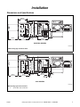
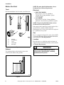
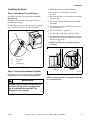
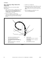
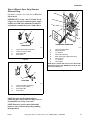
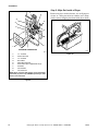
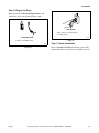
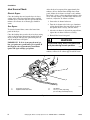
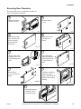
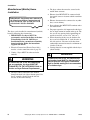
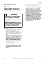
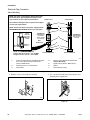
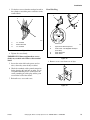
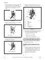
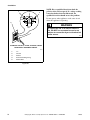
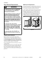
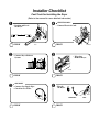
Installation
Automatic Clothes
Dryers
Electric and Gas Models
D715I
Para bajar una copia de estas instrucciones en español, visite www.comlaundry.com.
Keep These Instructions for Future Reference.
(If this machine changes ownership, this manual must accompany machine.)
www.comlaundry.com
Part No. 510963R5
June 2007
WARNING
FOR YOUR SAFETY, the information in this manual must be followed to minimize the risk
of fire or explosion or to prevent property damage, personal injury or death.
W033
• Do not store or use gasoline or other flammable vapors and liquids in the vicinity of this or
any other appliance.
• WHAT TO DO IF YOU SMELL GAS:
– Do not try to light any appliance.
– Do not touch any electrical switch; do not use any phone in your building.
– Clear the room, building or area of all occupants.
– Immediately call your gas supplier from a neighbor’s phone. Follow the gas supplier’s
instructions.
– If you cannot reach your gas supplier, call the fire department.
• Installation and service must be performed by a qualified installer, service agency or the
gas supplier.
W052
The following information applies to the state of Massachusetts, USA.
●
This appliance can only be installed by a Massachusetts licensed plumber or gas fitter.
●
This appliance must be installed with a 36 inch (91 cm) long flexible gas connector.
●
A “T-Handle” type gas shut-off valve must be installed in the gas supply line to this appliance.
●
This appliance must not be installed in a bedroom or bathroom.
510963
© Copyright, Alliance Laundry Systems LLC – DO NOT COPY or TRANSMIT
1
Notes
2
© Copyright, Alliance Laundry Systems LLC – DO NOT COPY or TRANSMIT
510963
Table of
Contents
Replacement Parts ..............................................................................
5
Installation...........................................................................................
Dimensions and Specifications.............................................................
Before You Start ...................................................................................
Tools ................................................................................................
Exhaust.............................................................................................
Electrical ..........................................................................................
Gas ...................................................................................................
Location ...........................................................................................
Installing the Dryer ...............................................................................
Step 1: Position and Level the Dryer ...............................................
Step 2: Connect Dryer Exhaust System ...........................................
Step 3: (Gas Dryer Only) Connect Gas Supply Pipe .......................
Step 4: (Electric Dryer Only) Connect Electrical Plug ....................
Step 5: Wipe Out Inside of Dryer ....................................................
Step 6: Plug In the Dryer .................................................................
Step 7: Check Installation ................................................................
Heat Source Check ...............................................................................
Electric Dryers .................................................................................
Gas Dryers .......................................................................................
Reversing Door Procedure....................................................................
Manufactured (Mobile) Home Installation...........................................
Electrical Requirements........................................................................
Electric Dryers .................................................................................
Gas Dryers .......................................................................................
Gas Requirements.................................................................................
Location Requirements.........................................................................
Dryer Exhaust Requirements................................................................
Exhaust System Materials................................................................
Make-Up Air Requirements.............................................................
Exhaust System ................................................................................
Exhaust Direction.............................................................................
Exhaust System Maintenance ..........................................................
Dryer Airflow...................................................................................
7
7
8
8
8
8
8
8
9
9
9
10
11
12
13
13
14
14
14
15
16
17
17
21
23
25
26
26
26
27
27
28
28
Maintenance ........................................................................................
User-Maintenance Instructions.............................................................
Lubrication .......................................................................................
Care of Your Dryer ..........................................................................
Exhaust System ................................................................................
Information for Handy Reference.........................................................
29
29
29
29
29
30
Installer Checklist................................................................. Back Cover
© Copyright 2007, Alliance Laundry Systems LLC
All rights reserved. No part of the contents of this book may be reproduced or transmitted in any form or by any
means without the expressed written consent of the publisher.
510963
© Copyright, Alliance Laundry Systems LLC – DO NOT COPY or TRANSMIT
3
Notes
4
© Copyright, Alliance Laundry Systems LLC – DO NOT COPY or TRANSMIT
510963
Replacement Parts
If replacement parts are required, contact the source
where you purchased your dryer, or contact:
Alliance Laundry Systems LLC
Shepard Street
P.O. Box 990
Ripon, WI 54971-0990
Phone: (920) 748-3950
for the name and address of the nearest authorized
parts distributor.
510963
© Copyright, Alliance Laundry Systems LLC – DO NOT COPY or TRANSMIT
5
Notes
6
© Copyright, Alliance Laundry Systems LLC – DO NOT COPY or TRANSMIT
510963
Installation
Dimensions and Specifications
23.5 in.
(59.7 cm)
28 in.
(71.1 cm)
15.4 in. (39.1 cm)
*43 in. (109.2 cm)
0.4 in.
(1.1 cm)
*15.44 in.
(39.2 cm)
*4.0 in. (10.2 cm)
*4.5 in.
(11.4 cm)
*36 in. (91.4 cm)
8.0 in.
(20.3 cm)
*40.25 in. (102.24 cm)
22.38 in.
(56.85 cm)
26.9 in.
(68.3 cm)
DRY2208N
ELECTRIC DRYERS
DRY2208N
* With leveling legs turned into base.
23.5 in.
(59.7 cm)
28 in.
(71.1 cm)
26.9 in.
(68.3 cm)
2.3 in.
(6 cm)
*15.44 in. (39.2 cm)
15.4 in. (39.1 cm)
*43 in. (109.2 cm)
0.4 in.
(1.1 cm)
*4.0 in. (10.2 cm)
*4.5 in.
(11.4 cm)
*36 in. (91.4 cm)
8.0 in.
(20.3 cm)
*40.25 in. (102.24 cm)
22.38 in.
(56.85 cm)
*2.8 in.
(7 cm)
DRY2209N
1
GAS DRYERS
DRY2209N
*With leveling legs turned into base.
1
510963
3/8 in. NPT Gas Connection
© Copyright, Alliance Laundry Systems LLC – DO NOT COPY or TRANSMIT
7
Installation
Before You Start
NOTE: For more detailed information, refer to
Section on Dryer Exhaust Requirements.
Tools
Electrical
For most installations, the basic tools you will need are:
●
ELECTRIC DRYER
Dryer needs a 3 or 4 wire 120/240 or
120/208 Volt, 30 Amp, 60 Hertz, 1 phase
electrical supply.
●
GAS DRYER
Dryer needs a 120 Volt, 15 Amp, 60 Hertz,
polarized 3-slot effectively grounded receptacle.
2
1
3
NOTE: For more detailed information, refer to
Section on Electrical Requirements.
If the supply cord is damaged, it must be replaced by a
special cord or assembly available from the
manufacturer or its service agent and is to be replaced
by a qualified service person.
5
4
Gas
D818I
1
2
3
4
5
Wrench
Screwdrivers
Level
Teflon Tape
Duct Tape
Dryer is equipped for Natural Gas with a 3/8 inch NPT
gas supply connection. For more detailed information,
refer to Section on Gas Requirements.
Location
Place the dryer on a solid floor with an adequate air
supply. For more detailed information, refer to Section
on Location Requirements.
Figure 1
WARNING
Exhaust
Any disassembly requiring the use of
tools must be performed by a suitably
qualified service person.
Use rigid metal duct and exhaust the dryer to the
outside by the shortest route possible.
W299
D314I
Figure 2
8
© Copyright, Alliance Laundry Systems LLC – DO NOT COPY or TRANSMIT
510963
Installation
Installing the Dryer
●
DO NOT use plastic or thin foil ducting.
●
Locate dryer so exhaust duct is as short as
possible.
For further assistance refer to Section on Location
Requirements.
●
Be certain old ducts are cleaned before installing
your new dryer.
Install dryer before washer. This allows room for
attaching exhaust duct.
●
Use 4 inch (102 mm) diameter rigid or flexible
metal duct.
Place the dryer in position, and adjust the legs until the
dryer is level from side to side and front to back.
●
The male end of each section of duct must point
away from the dryer.
●
Use as few elbows as possible.
●
Use duct tape or pop-rivets on all duct joints.
●
Ductwork that runs through unheated areas must
be insulated to help reduce condensation and lint
build-up on pipe walls.
●
Failure to exhaust dryer properly will void
warranty.
Step 1: Position and Level the Dryer
2
1
3
D259I
D669I
D699I
1
2
3
Dryer Base
Level
Leveling Leg
Figure 3
DO
DON’T
Step 2: Connect Dryer Exhaust System
For further assistance refer to Sections on Location
Requirements and Dryer Exhaust Requirements.
DRY1915N
DRY1915N
Figure 4
NOTE: Venting materials are not supplied with the
dryer (obtain locally).
WARNING
A clothes dryer produces combustible lint.
To reduce the risk of fire and combustion
gas accumulation the dryer MUST be
exhausted to the outdoors.
W116
510963
© Copyright, Alliance Laundry Systems LLC – DO NOT COPY or TRANSMIT
9
Installation
Step 3: (Gas Dryer Only) Connect Gas
Supply Pipe
3. Connect to gas supply pipe.
For further assistance, refer to Section on Gas
Requirements.
1. Make certain your dryer is equipped for use with
the type of gas in your laundry room. Dryer is
equipped at the factory for Natural Gas with a
3/8 inch NPT gas connection.
4. Tighten all connections securely. Turn on gas and
check all pipe connections (internal & external)
for gas leaks with a non-corrosive leak detection
fluid.
5. For L.P. (propane) gas connection, refer to
Section on Gas Requirements.
2. Remove the shipping cap from the gas
connection at the rear of the dryer. Make sure you
do not damage the pipe threads when removing
the cap.
1
2
3
5
4
D233I
D233I
1
2
3
New Stainless Steel Flexible Connector –
Use only if allowed by local codes
(Use Design CSA Certified Connector)
1/8 in. NPT Pipe Plug (For checking inlet gas
pressure)
Equipment Shut-Off Valve – Install within
6 ft. (1.8 m) of dryer
4
5
Black Iron Pipe
Shorter than 20 ft. (6.1 m) – Use 3/8 in.
(9.5 mm) pipe
Longer than 20 ft. (6.1 m) – Use 1/2 in.
(12.7 mm) pipe
3/8 in. NPT Gas Connection
Figure 5
10
© Copyright, Alliance Laundry Systems LLC – DO NOT COPY or TRANSMIT
510963
Installation
Step 4: (Electric Dryer Only) Connect
Electrical Plug
1
8
2
For further assistance, refer to Section on Electrical
Requirements.
7
IMPORTANT: Use only a new U.L. listed No. 10
(copper wire only) three conductor power supply
cord kit rated 240 Volts (minimum) 30 Amperes
and labeled as suitable for use in a clothes dryer.
3
6
4
1
2
3
5
4
THREE-WIRE CONNECTION
THREE WIRE
D679I
D679I
D275I
1
2
3
4
1
2
3
4
5
6
7
8
Typical Three-Wire Receptable
Power Cord (Three-Wire)
Strain Relief Nut
Strain Relief
Figure 6
Ground to Neutral Wire
Neutral Terminal
“L2” Terminal
Center Wire (Neutral)
Strain Relief (Not supplied with dryer)
Ground Screw
“L1” Terminal
Ground Wire
NOTE: Dryer is shown with access cover removed for
illustration purposes only. NEVER operate dryer with
access cover removed.
1
2
Figure 8
3
4
FOUR WIRE
D006I
1
2
3
4
Typical Four-Wire Receptacle
Power Cord (Four-Wire)
Strain Relief Nut
Strain Relief
Figure 7
NOTE: For more detailed information on
connecting three-wire or four-wire plugs, refer to
Section on Electrical Plug Connection.
NOTE: Four-wire cord is required for mobile
homes or where codes do not permit grounding
through neutral.
510963
© Copyright, Alliance Laundry Systems LLC – DO NOT COPY or TRANSMIT
11
Installation
Step 5: Wipe Out Inside of Dryer
1
Before using dryer for the first time, use an all-purpose
cleaner, or a detergent and water solution, and a damp
cloth to remove shipping dust from inside dryer drum.
2
8
3
9
8
4
5
6
7
D618I
FOUR-WIRE CONNECTION
D680I
D618I
D680I
1
2
3
4
5
6
7
8
9
“L1” Terminal
Neutral Terminal
“L2” Terminal
Black Wire
White Wire (Neutral)
Strain Relief (Not supplied with dryer)
Red Wire
Ground Wire
Ground Screw
Figure 10
NOTE: Dryer is shown with access cover removed for
illustration purposes only. NEVER operate dryer with
access cover removed.
Figure 9
12
© Copyright, Alliance Laundry Systems LLC – DO NOT COPY or TRANSMIT
510963
Installation
Step 6: Plug In the Dryer
Refer to Section on Electrical Requirements, and
connect the dryer to an electrical power source.
D254I
GAS DRYER
Plug cord into separately fused
15 Amp circuit.
ELECTRIC DRYER
D254I
Figure 12
Connect to 30 Amp circuit.
D275I
Figure 11
510963
Step 7: Check Installation
Refer to Installer Checklist on the back cover of this
manual and make sure that dryer is installed correctly.
© Copyright, Alliance Laundry Systems LLC – DO NOT COPY or TRANSMIT
13
Installation
Heat Source Check
After the dryer has operated for approximately five
minutes, observe burner flame through lower front
panel. Adjust the air shutter to obtain a soft, uniform
blue flame. (A lazy, yellow-tipped flame indicates lack
of air. A harsh, roaring, very blue flame indicates too
much air.) Adjust the air shutter as follows:
Electric Dryers
Close the loading door and start the dryer in a heat
setting (refer to the Operating Instructions supplied
with the dryer). After the dryer has operated for three
minutes, the exhaust air or exhaust pipe should be
warm.
1. Loosen the air shutter lockscrew.
2. Turn the air shutter to the left to get a luminous
yellow-tipped flame, then turn it back slowly to
the right to obtain a steady, soft blue flame.
Gas Dryers
To view the burner flame, remove the lower front
panel of the dryer.
3. After the air shutter is adjusted for proper flame,
tighten the air shutter lockscrew securely.
Close the loading door, start the dryer in a heat setting
(refer to the Operating Instructions supplied with the
dryer); the dryer will start, the igniter will glow red
and the main burner will ignite.
4. Reinstall the lower front panel.
WARNING
IMPORTANT: If all air is not purged out of gas
line, gas igniter may go off before gas is ignited. If
this happens, after approximately two minutes
igniter will again attempt gas ignition.
For personal safety, lower front panel must
be in place during normal operation.
W046
After the dryer has operated for approximately three
minutes, exhaust air or exhaust pipe should be warm.
1
2
4
3
D702I
D702I
1
2
Air Shutter Lockscrew
Appliance Main Gas Valve
3
4
Air Shutter
1/8 in. (3.1 mm) Pipe Plug
(For checking manifold pressure)
Figure 13
14
© Copyright, Alliance Laundry Systems LLC – DO NOT COPY or TRANSMIT
510963
Installation
Reversing Door Procedure
The door on this dryer is completely reversible. To
reverse door proceed as follows:
1
2
Remove four hinge
attaching screws.
Remove all nine
screws.
D675I
D675I
D272P
3
4
Pull bottom of door
liner out, then pull
down, removing
door liner from
door panel.
Rotate door panel
180 degrees as
shown.
B
A
DRY1916N
DRY1916N
D273P
5
6
Remove door strike
from door liner and
reinstall on opposite
side.
Insert liner under
flange on bottom of
door, then push top
of door liner into
place.
B
A
DRY1918N
DRY1918N
DRY1917N
DRY1917N
7
8
Reinstall nine
screws removed in
Step 2.
Using the screwdriver,
remove two door
plugs, and reinstall on
opposite side of door
opening.
DRY1919N
DRY1919N
D620I D620I
9
Reinstall four hinge
attaching screws.
removed in Step 1.
D623I
D623I
510963
© Copyright, Alliance Laundry Systems LLC – DO NOT COPY or TRANSMIT
15
Installation
Manufactured (Mobile) Home
Installation
IMPORTANT: Installation must conform to
the Manufactured Home Construction and
Safety Standards, Title 24 CFR, Part 32-80
or Standard CAN/CSA-Z240 MH.
●
The dryer exhaust duct must be secured to the
mobile home structure.
●
Exhaust ducts MUST NOT be connected with
sheet metal screws or fasteners which extend into
the duct.
●
Exhaust duct must not be connected to any other
duct, vent or chimney.
●
Dryer exhaust duct MUST NOT terminate under
the mobile home.
●
For proper operation, it is important that the dryer
has an ample amount of outside make-up air. The
free area of any opening for the introduction of
outside air must be at least 25 in2 (163 cm2).
●
When exhausting the dryer to the outdoors, the
dryer can be installed with “0” inch clearance at
the sides and rear. Clearance of the duct from
combustible construction must be a minimum of
2 inches (5.08 cm).
●
Venting materials are not supplied with the dryer
(obtain locally).
The dryer can be installed in a manufactured (mobile)
home by following these instructions:
1. IMPORTANT: Gas dryers MUST be
permanently attached to the floor at the time
of installation. Order No. 526P3 Dryer
Installation Kit for a manufactured (mobile)
home installation. Follow the instructions
supplied with the kit.
2. Electrical Connections (Electric Dryer Only)
must be a 4-wire connection, refer to page 19.
3. Venting – Dryer MUST be exhausted to the
outdoors.
WARNING
WARNING
To reduce the risk of fire and combustion
gas accumulation, the dryer MUST BE
EXHAUSTED TO THE OUTDOORS. Refer to
Section on Dryer Exhaust Requirements.
To reduce the risk of fire, the exhaust duct
and weather hood MUST be fabricated of a
material that will not support combustion.
Rigid or flexible metal pipe is recommended
for a clothes dryer.
W048
W047
●
16
The dryer can be exhausted to the outdoors
through the back, left, right or bottom panel. Gas
dryers cannot be exhausted out the left side
because of the burner housing.
© Copyright, Alliance Laundry Systems LLC – DO NOT COPY or TRANSMIT
510963
Installation
Electrical Requirements
●
If branch circuit to dryer is fifteen feet (4.50 m)
or less in length, use U.L. (Underwriters
Laboratories) listed No. 10 AWG wire (copper
wire only), or as required by local codes. If over
fifteen feet (4.50 m), use U.L. (Underwriters
Laboratories) listed No. 8 AWG wire (copper
wire only), or as required by local codes. Allow
sufficient slack in wiring so dryer can be moved
from its normal location when necessary.
●
The power cord (pigtail) connection between
wall receptacle and dryer terminal block IS NOT
supplied with dryer. Type of pigtail and gauge
of wire must conform to local codes and with
instructions mentioned on the following pages.
●
The method of wiring the dryer is optional and
subject to local code requirements. Refer to
examples on next page.
Electric Dryers
(120/240 Volt, 60 Hertz, 3-Wire Installation)
(120/208 Volt, 60 Hertz, 3-Wire Installation)
NOTE: The wiring diagram is located inside the
control hood.
WARNING
To reduce the risk of fire, electric shock,
serious injury or death, all wiring and
grounding MUST conform with the latest
edition of the National Electrical Code,
ANSI/NFPA 70, or the Canadian Electrical
Code, CSA C22.1, and such local
regulations as might apply. It is the
customer’s responsibility to have the wiring
and fuses checked by a qualified electrician
to make sure your home has adequate
electrical power to operate the dryer.
W113
Grounding Instructions
●
This dryer must be connected to a grounded
metal, permanent wiring system; or an
equipment-grounding conductor must be run
with the circuit conductors and connected to the
equipment-grounding terminal or lead on the
dryer.
●
The dryer has its own terminal block that must be
connected to a separate branch, 60 Hertz, single
phase circuit, AC (alternating current) circuit,
fused at 30 Amperes (the circuit must be fused
on both sides of the line). ELECTRICAL
SERVICE FOR THE DRYER SHOULD BE
OF MAXIMUM RATED VOLTAGE LISTED
ON THE NAMEPLATE. DO NOT
CONNECT DRYER TO 110, 115, OR
120 VOLT CIRCUIT. Heating elements are
available for field installation in dryers which are
to be connected to electrical service of different
voltage than that listed on nameplate, such as
208 Volt.
510963
© Copyright, Alliance Laundry Systems LLC – DO NOT COPY or TRANSMIT
17
Installation
Electrical Plug Connection
Three-Wire Plug
NOTE: The power cord (pigtail) is NOT supplied with
the electric dryer. Type of pigtail and gauge of wire
must conform to local codes and instructions.
POWER SUPPLY
POWER SUPPLY
1
The method of wiring the dryer is optional and subject
to local code requirements.
2
NOTE: Connect the dryer to the power supply with the
MAXIMUM RATED VOLTAGE listed on the nameplate.
A typical
30-Amp
Three-Wire
Receptacle
NEMA Type
10-30R
3
INTERMEDIATE
FUSE BOX (may
be omitted if
service entrance
box is fused)
4
WALL
RECEPTACLE
5
120 ± 12
V.A.C.
120 ± 12
V.A.C.
INTERMEDIATE
SHUT-OFF BOX
(may or may not
be fused)
6
7
240 ± 12
V.A.C.
L1
NOTE: Use COPPER WIREonly.
Shorter than 15 ft. (4.5 m) – use 10 AWG
Longer than 15 ft. (4.5 m) – use 8 AWG
L2
L1
PIGTAIL CONNECTION
L2
DIRECT CONNECTION
D816I
1
3 Wire Grounded Neutral 120/240 Volt, 60 Hertz
AC 1 Phase Service Entrance Switch Box
(Refer to NOTE above)
2
3
30 Ampere Fuses or Circuit Breaker
Neutral Wire
4
5
6
7
Metallic or Non-Metallic Sheathed Cable
(Copper Wire Only)
Pigtail to Dryer (Refer to NOTE above)
Neutral
Terminal Block in Dryer
Figure 14
1. Remove access cover from rear of dryer.
2. Use a strain relief and insert end of power cord
through power supply hole.
D695I
D696I
Figure 15
Figure 16
18
© Copyright, Alliance Laundry Systems LLC – DO NOT COPY or TRANSMIT
510963
Installation
3. Use the three screws from the envelope located in
the cylinder to attach the power cord wires to the
terminal block.
Four-Wire Plug
2
1
1
2
3
4
3
D286I
1
2
3
“L1” Terminal
Neutral Terminal
“L2” Terminal
Figure 17
4. Tighten all screws firmly.
IMPORTANT: Failure to tighten these screws
firmly may result in wire failure at the terminal
block.
D815I
1
2
3
4
Typical Four-Wire Receptacle
Power Cord – Not Supplied with Dryer
(Four-Wire)
Strain Relief Nut
Strain Relief
Figure 18
1. Remove access cover from rear of dryer.
5. Secure the strain relief to the power cord, or
wires, where they enter the dryer cabinet.
6. Check the continuity of the ground connection
before plugging the cord into an outlet. Use an
acceptable indicating device connected to the
center grounding pin of the plug and the green
screw on the back of the cabinet.
7. Reinstall access cover and screw.
D695I
Figure 19
510963
© Copyright, Alliance Laundry Systems LLC – DO NOT COPY or TRANSMIT
19
Installation
2. Remove the three screws holding the three wires
to the terminal block terminals. Save these
screws. Loosen the strain relief screw and pull
the cord or wires out through the rear of the
dryer.
5. Attach power cord ground (green) wire to rear
bulkhead using ground screw removed in Step 3.
1
7
6
5
2
4
DRY1920N
3
D696I
Figure 20
DRY1920N
3. Remove ground screw and save for use in Step 5.
Remove wire and use in Step 6.
1
1
2
3
4
5
6
7
White
“L2” Terminal
Black
Green
Red
Neutral Terminal
“L1” Terminal
Figure 23
6. Use the three screws from the envelope located in
the cylinder to attach the remaining power cord
wires to the terminal block as follows:
D697I
D697I
1
a. Red wire to “L1” terminal.
b. Black wire to “L2” terminal.
Ground Screw
c. White wire to Neutral terminal.
Figure 21
4. Use a strain relief and insert end of power cord
through power supply hole.
NOTE: When installing the white wire, loop the
free eyelet end of the ground wire (removed in
Step 3) and attach along with the white wire to the
neutral (center) terminal on the terminal block.
7. Tighten all screws firmly.
1
IMPORTANT: Failure to tighten these screws
firmly may result in wire failure at the terminal
block.
D698I
D698I
1
Power Cord Ground Wire
8. Check the continuity of the ground connection
before plugging the cord into an outlet. Use an
acceptable indicating device connected to the
center grounding pin of the plug and the green
screw on the back of the cabinet.
9. Reinstall access cover and screw.
Figure 22
20
© Copyright, Alliance Laundry Systems LLC – DO NOT COPY or TRANSMIT
510963
Installation
Gas Dryers
NOTE: The wiring diagram is located inside the
control hood.
WARNING
To reduce the risk of fire, electric shock,
serious injury or death, all wiring and
grounding MUST conform with the latest
edition of the National Electrical Code,
ANSI/NFPA 70, or the Canadian Electrical
Code, CSA C22.1, and such local
regulations as might apply. It is the
customer’s responsibility to have the wiring
and fuses checked by a qualified electrician
to make sure your home has adequate
electrical power to operate the dryer.
W113
●
DO NOT
OVERLOAD
CIRCUITS
●
DO NOT
USE AN
ADAPTER
●
DO NOT
USE AN
EXTENSION
CORD
WARNING
Improper connection of the equipmentgrounding conductor can result in a risk of
electric shock. Check with a qualified
electrician or service person if you are in
doubt as to whether the dryer is properly
grounded.
W038
Do not modify the plug provided with the dryer – if it
will not fit the outlet, have a proper outlet installed by
a qualified electrician.
WARNING
This dryer is equipped with a three-prong
(grounding) plug for your protection against
shock hazard and should be plugged
directly into a properly grounded threeprong receptacle. Do not cut or remove the
grounding prong from this plug.
W036
D009I
Figure 24
Grounding Instructions
The dryer must be grounded. In the event of
malfunction or breakdown, grounding will reduce the
risk of electric shock by providing a path of least
resistance for electric current. The dryer is equipped
with a cord having an equipment-grounding conductor
and a 3 prong grounding plug. The three-prong
grounding plug on the power cord should be plugged
directly into a polarized three-slot effectively
grounded receptacle rated 110/120 Volts AC
(alternating current) 15 Amps.
510963
© Copyright, Alliance Laundry Systems LLC – DO NOT COPY or TRANSMIT
21
Installation
2
1
120 ± 12
V.A.C.
3
NOTE: Have a qualified electrician check the
polarity of the wall receptacle. If a voltage reading
is measured other than that illustrated, the
qualified electrician should correct the problem.
Do not operate other appliances on the same circuit
when this appliance is operating.
0
V.A.C.
5
WARNING
120 ± 12
V.A.C.
To reduce the risk of an electric shock or
fire, DO NOT use an extension cord or an
adapter to connect the dryer to the electrical
power source.
4
W037
STANDARD 120 VOLT, 15 AMP, 60 HERTZ, 3 WIRE
EFFECTIVELY GROUNDED CIRCUIT
D090I
1
2
3
4
5
“L1”
Ground
Neutral
Round Grounding Prong
Neutral Side
Figure 25
22
© Copyright, Alliance Laundry Systems LLC – DO NOT COPY or TRANSMIT
510963
Installation
Gas Requirements
NOTE: The gas service to a gas dryer must
conform with the local codes and ordinances, or in
the absence of local codes and ordinances, with the
latest edition of the National Fuel Gas Code ANSI
Z223.1/NFPA 54 or the CAN/CGA-B149, National
Gas Installation Code.
Natural Gas, 1000 Btu/ft3 (37.3 MJ/m3) service must
be supplied at 6.5 ± 1.5 inch water column pressure.
For proper operation at altitudes above 2500 feet
(760 m) the natural gas valve spud orifice size must be
reduced to ensure complete combustion. Refer to
Table 1.
L.P. (Liquefied Petroleum) Gas, 2500 Btu/ft3
(93.1 MJ/m3) service must be supplied at 10 ± 1.5 inch
water column pressure.
NOTE: DO NOT connect the dryer to L.P. Gas
Service without converting the gas valve. An LPK1
Sales Accessory (L.P. Gas Conversion Kit 649P3)
must be installed.
NOTE: The dryer and its appliance main gas valve
must be disconnected from the gas supply piping
system during any pressure testing of that system
at test pressures in excess of 1/2 psi (3.45 kPa).
Refer to Figure 13.
NOTE: When connecting to a gas line, an
equipment shut-off valve must be installed within
6 feet (1.8 m) of the dryer. An 1/8 in. NPT pipe plug
must be installed as shown. Refer to Figure 26.
WARNING
To reduce the risk of gas leaks, fire or
explosion:
• The dryer must be connected to the type
of gas as shown on nameplate located in
the door recess.
• Use a new flexible stainless steel
connector.
• Use pipe joint compound insoluble in L.P.
(Liquefied Petroleum) Gas, or Teflon tape,
on all pipe threads.
• Purge air and sediment from gas supply
line before connecting it to the dryer.
Before tightening the connection, purge
remaining air from gas line to dryer until
odor of gas is detected. This step is
required to prevent gas valve
contamination.
• Do not use an open flame to check for gas
leaks. Use a non-corrosive leak detection
fluid.
• Any disassembly requiring the use of
tools must be performed by a suitably
qualified service person.
W316
Natural Gas Altitude Adjustments
Altitude
feet
3000
6000
8000
9000
10,000
m
915
1830
2440
2740
3050
Orifice Size
#
43
44
45
46
47
inches
0.0890
0.0860
0.0820
0.0810
0.0785
mm
2.26
2.18
2.08
2.06
1.99
Part No.
503778
58719
503779
503780
503781
Table 1
510963
© Copyright, Alliance Laundry Systems LLC – DO NOT COPY or TRANSMIT
23
Installation
1
2
3
5
4
D233I
D233I
1
2
3
New Stainless Steel Flexible Connector –
Use only if allowed by local codes
(Use Design CSA Certified Connector)
1/8 in. NPT Pipe Plug (For checking inlet gas
pressure)
Equipment Shut-Off Valve – Install within
6 ft. (1.8 m) of dryer
4
5
Black Iron Pipe
Shorter than 20 ft. (6.1 m) – Use 3/8 in.
(9.5 mm) pipe
Longer than 20 ft. (6.1 m) – Use 1/2 in.
(12.7 mm) pipe
3/8 in. NPT Gas Connection
Figure 26
24
© Copyright, Alliance Laundry Systems LLC – DO NOT COPY or TRANSMIT
510963
Installation
Location Requirements
Select a location with a solid floor. Dryers installed in
residential garages must be elevated 18 inches (46 cm)
above the floor.
No other fuel burning appliance should be installed in
the same closet with the dryer.
The dryer must not be installed or stored in an area
where it will be exposed to water and/or weather.
Leveling legs can be adjusted from inside the dryer
with a 1/4 inch driver. All four legs must rest firmly on
the floor so the weight of the dryer is evenly
distributed. The dryer must not rock.
The dryer needs sufficient clearance and an adequate
air supply for proper operation and ventilation, and for
easier installation and servicing. (Minimum clearances
are shown below.)
F
1
B
2 (G)
E
D
A
**42 in.
(106.7 cm)
F
A
A
FRONT VIEW
(w/o Closet Door)
C
SIDE VIEW
(Closet Door)
3
FRONT VIEW
(Closet Door)
D823I
Area
A
B
C
D
Description
Free Standing/Alcove
Installation
0 in. (0 cm)
12 in. (30.5 cm)
Not Applicable
2 in. (5.1 cm)
Closet Installation
Dryer sides and rear clearance
0 in. (0 cm)
Dryer top clearance
12 in. (30.5 cm)
Dryer front clearance
2 in. (5.1 cm)
Exhaust duct clearance to
2 in. (5.1 cm)
combustible material
E
Weather hood to ground
12 in. (30.5 cm)
12 in. (30.5 cm)
clearance
F
Distance from floor or ceiling to Not Applicable
3 in. (7.6 cm)
hole edge
G*
Area of centered air openings in Not Applicable
40 sq. in./open (260 sq. cm)
closet door
*Louvered door with equivalent air openings is acceptable. (Minimum clearances are shown.)
1
2
3
Closet Door
Centered Air Openings (G) (2 Openings
minimum)
Outer Wall of Enclosure
**NOTE: For new installations, locate top of wall vent 42 inches (106.7 cm) above floor to make venting
easier to connect.
Figure 27
510963
© Copyright, Alliance Laundry Systems LLC – DO NOT COPY or TRANSMIT
25
Installation
Dryer Exhaust Requirements
Make-Up Air Requirements
For proper operation it is important that you locate the
dryer in an area that has an ample amount of make-up
air to replace the amount exhausted by the dryer.
WARNING
A clothes dryer produces combustible lint.
To reduce the risk of fire and combustion
gas accumulation the dryer MUST be
exhausted to the outdoors.
W116
This gas appliance contains or produces a
chemical or chemicals which can cause
death or serious illness and which are
known to the State of California to cause
cancer, birth defects, or other reproductive
harm. To reduce the risk from substances in
the fuel or from fuel combustion, make sure
this appliance is installed, operated, and
maintained according to the instructions in
this manual.
A dryer exhausts 220 cfm (measured at back of dryer).
Energy efficient homes with low air infiltration rates
should be equipped with an air exchanger that can
accommodate on demand make-up air needs in the
home. These devices can be obtained through your
building contractor or building material suppliers.
W115
To reduce the risk of fire and the
accumulation of combustion gases, DO NOT
exhaust dryer air into a window well, gas
vent, chimney or enclosed, unventilated
area, such as an attic, wall, ceiling, crawl
space under a building or concealed space
of a building.
W045
DO
DON’T
DRY1915N
DRY1915N
Figure 28
To reduce the risk of fire, DO NOT use
plastic or thin foil ducting to exhaust the
dryer.
W354
Exhaust System Materials
Exhaust duct must be four inches (10.2 cm) in
diameter having no obstructions. Rigid metal duct is
recommended. Non-combustible flexible metal duct is
acceptable. Do not use plastic pipe or thin foil ducting,
because it contributes to poor drying performance and
collects lint, which can lead to a fire hazard.
Never install flexible duct in concealed spaces, such as
a wall or ceiling.
DO NOT use sheet metal screws on exhaust pipe joints
or other fastening means which extend into the duct
that could catch lint and reduce the efficiency of the
exhaust system. Secure all duct joints with duct tape or
pop-rivets.
26
© Copyright, Alliance Laundry Systems LLC – DO NOT COPY or TRANSMIT
510963
Installation
Exhaust System
Dryer is shipped from factory ready for rear exhaust;
no kits required.
IMPORTANT: Keep exhaust duct as short as
possible.
Exhausting the dryer through sides or bottom can be
accomplished by installing a DK1 Sales Accessory
(Directional Exhaust Kit 528P3) available as optional
equipment at extra cost.
NOTE: Be certain old ducts are cleaned before
installing your new dryer.
For best drying results, recommended maximum
length of exhaust system is shown in table below.
To prevent backdraft when dryer is not in operation,
outer end of exhaust pipe must have a weather hood
with hinged dampers (obtain locally).
NOTE: Weather hood should be installed at least
12 inches (30.5 cm) above the ground. Larger
clearances may be necessary for installations where
heavy snowfall can occur.
Exhaust Direction
The dryer can be exhausted to the outdoors through the
back, left, right or bottom of the dryer. EXCEPTION:
Gas dryers cannot be vented out the left side
because of the burner housing.
528P3 DIRECTIONAL EXHAUST KIT
D328I
Figure 29
Number of
90° Elbows
Weather Hood Type
Recommended
4 in.
(10.2 cm)
Use Only for Short Run installations
4 in.
(10.2 cm)
D673I
0
1
2
3
4
0
1
2
3
4
2-1/2 in.
(6.35 cm)
D802I
Maximum length of 4 in. (10.2 cm) diameter rigid metal duct.
65 feet (19.8 m)
55 feet (16.8 m)
55 feet (16.8 m)
47 feet (14.3 m)
47 feet (14.3 m)
41 feet (12.5 m)
36 feet (11.0 m)
30 feet (9.1 m)
28 feet (8.5 m)
22 feet (6.7 m)
Maximum length of 4 in. (10.2 cm) diameter flexible metal duct.
45 feet (13.7 m)
35 feet (10.7 m)
35 feet (10.7 m)
27 feet (8.2 m)
30 feet (9.1 m)
21 feet (6.4 m)
25 feet (7.6 m)
17 feet (5.2 m)
20 feet (6.1 m)
15 feet (4.5 m)
NOTE: Deduct 6 feet (1.8 m) for each additional elbow.
Table 2
510963
© Copyright, Alliance Laundry Systems LLC – DO NOT COPY or TRANSMIT
27
Installation
Exhaust System Maintenance
Dryer Airflow
The dryer interior and the complete exhaust system
should be inspected after one year of use and cleaned
if necessary. Inspect and clean exhaust duct every one
to two years as required thereafter. The weather hood
should be checked frequently to make sure the
dampers move freely, dampers are not pushed in and
that nothing has been set against them. This
maintenance work should be done by a qualified
service person.
Efficient dryer operation requires proper dryer airflow.
Proper dryer airflow can be evaluated by measuring
the static pressure.
Static pressure in the dryer’s exhaust duct should be no
greater than that shown in the illustration below.
(Check with dryer running and no load.)
NOTE: This can be measured with a manometer
placed on the exhaust duct approximately two feet
(61 cm) from the dryer. Refer to Figure 31.
WARNING
MAXIMUM STATIC
PRESSURE IN
WATER COLUMN
To reduce the risk of electric shock,
disconnect the electrical service to the dryer
before cleaning.
0.6 inches (1.5 cm)
W043
1
Exhausting the dryer in hard-to-reach locations can be
accomplished by installing the 521P3 Flexible Metal
Vent Kit, available as optional equipment at extra cost.
The kit comes in two halves that can be separately
attached to the dryer and wall outlet. Once attached,
the dryer can be slid back into position and the two
halves can be connected from the front.
2
DR012A-IN
MEASURING STATIC PRESSURE
D012I
1
2
Manometer
Exhaust Duct
Figure 31
D622I
521P3 FLEXIBLE METAL VENT KIT
D622I
Figure 30
28
© Copyright, Alliance Laundry Systems LLC – DO NOT COPY or TRANSMIT
510963
Maintenance
User-Maintenance Instructions
Exhaust System
Lubrication
The exhaust duct should be inspected after one year of
use and cleaned if necessary. Inspect and clean exhaust
duct every one to two years as required thereafter.
All moving parts are sealed in a permanent supply of
lubricant or are equipped with oilless bearings.
Additional lubrication will not be necessary.
Care of Your Dryer
The weather hood should be checked frequently to
make sure the dampers move freely, dampers are not
pushed in and that nothing has been set against them.
Clean the lint filter after drying each load. The lint
filter may be washed if needed. Annually remove lint
filter and screw to vacuum the duct under it.
Keep dryer area clear and free from combustible
materials, gasoline and other flammable vapors and
liquids.
Ordinarily, the dryer cylinder will need no care.
Do not obstruct the flow of combustion and ventilation
air.
Wipe the dryer cabinet as needed. If detergent, bleach
or other washing products have been spilled on the
dryer, wipe immediately. Some products will cause
permanent damage if spilled on the cabinet.
NOTE: Verify proper operation after servicing.
Use only a damp or sudsy cloth for cleaning the
control panel. Some spray prewash products may harm
the finish on the control panel.
NOTE: The wiring diagram is located inside the
control panel.
CAUTION
Label all wires prior to disconnection when
servicing controls. Wiring errors can cause
improper and dangerous operation.
W049
510963
© Copyright, Alliance Laundry Systems LLC – DO NOT COPY or TRANSMIT
29
Maintenance
Information for Handy Reference
Alliance Laundry Systems LLC
Shepard Street
P.O. Box 990
Ripon, WI 54971-0990
Date Purchased
Model Number
Serial Number
Dealer’s Name
Dealer’s Address
Phone Number
Service Agency
Service Agency Address
Phone Number
NOTE: Record the above information and keep your sales slip. Model and serial numbers are located
on the nameplate.
30
© Copyright, Alliance Laundry Systems LLC – DO NOT COPY or TRANSMIT
510963
Installer Checklist
Fast Track for Installing the Dryer
(Refer to the manual for more detailed information)
➊
➍
• Position and Level
the Dryer.
ELECTRIC ONLY
• Connect Electrical Cord.
LEVEL
LEVEL/NIVEL
D255I
D256I
CHECK
➋
CHECK
D259I
➎
• Connect Dryer Exhaust
System.
• Wipe Out
Inside of Dryer.
DRY1915N
DRY1915N
D618I
D618I
CHECK
➌
D699I
D699I
CHECK
➏
GAS ONLY
• Connect Gas Supply Pipe.
• Check for Gas Leaks.
• Plug In
the Dryer.
D254I
D254I
D275I
ELECTRIC
D258I
CHECK
CHECK
GAS