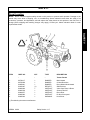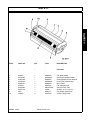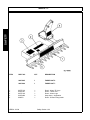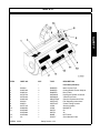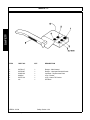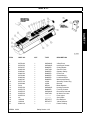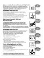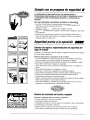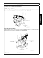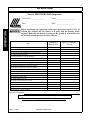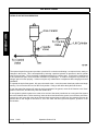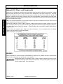
1
VERSA
BOOM ARM MOWER
Published 03/09
Part No. 02897300C
OPERATOR’S MANUAL
This Operator's Manual is an integral part of the safe operation of this machine and must
be maintained with the unit at all times. READ, UNDERSTAND, and FOLLOW the Safety
and Operation Instructions contained in this manual before operating the equipment. C01Cover
ALAMO INDUSTRIAL
®
1502 E. Walnut
Seguin, Texas 78155
210-372-3551
Email: [email protected]
©2009 Alamo Group Inc.
$0.00
To the Owner/Operator/Dealer
All implements with moving parts are potentially hazardous. There is no substitute for a cautious, safe-minded
operator who recognizes the potential hazards and follows reasonable safety practices. The manufacturer has
designed this implement to be used with all its safety equipment properly attached to minimize the chance of accidents.
BEFORE YOU START!!Read the safety messages on the implement and shown in your manual. Observe the
rules of safety and common sense!
WARRANTY INFORMATION:
Read and understand the complete Warranty Statement found in this Manual. Fill out the Warranty Registration
Form in full and return it to within 30 Days. Make certain the Serial Number of the Machine is recorded on the Warranty Card and on the Warranty Form that you retain.
In order to reduce accidents and enhance the safe operation of mowers, Alamo Industrial, in cooperation
with other industry manufacturers has developed the AEM/FEMA Industrial and Agricultural Mower
Safety Practices video and guide book.
The video will familiarize and instruct mower-tractor operators in safe practices when using industrial
and agricultural mowing equipment. It is important that Every Mower Operator be educated in the operation of their mowing equipment and be able to recognize the potential hazards that can occur while operating a mower. This video, along with the mower operator’s manual and the warning messages on the
mower, will significantly assist in this important education.
Your Authorized Alamo Industrial Dealer may have shown this video and presented you a DVD Video
when you purchased your mower. If you or any mower operator have not seen this video, Watch the
Video, Read this Operator’s Manual, and Complete the Video Guidebook before operating your new
mower. If you do not understand any of the instructions included in the video or operator’s manual or if
you have any questions concerning safety of operation, contact your supervisor, dealer or Alamo Industrial.
If you would like a VHS video tape of the video, please email [email protected] or Fax
AEM VHS Video at (830) 372-9529 or mail in a completed copy of the form on the back of this page to
AEM VHS Video 1502 E Walnut Street, Seguin, TX 78155. and request the VHS video version. Please
include your name, mailing address, mower model and serial number.
Every operator should be trained for each piece of equipment (Tractor and Mower), understand the
intended use, and the potential hazards before operating the equipment.
Alamo Industrial Division is willing to provide
one (1) AEM Mower Safety Practices Video
Please Send Me:
VHS Format – AEM/FEMA Mower Operator Safety Video
DVD Format – AEM/FEMA Mower Operator Safety Video
Mower Operator’s Manual
AEM Mower Operator’s Safety Manual
Requester Name
Phone:
Requester Address:
City
State
Zip Code
Mower Model:
Serial Number:
Date Purchased:
Dealer Salesperson:
Dealership Name:
Dealership Location:
Mail to:
AEM Video Services
1502 E Walnut street
Seguin, TX 78155
Or Fax to:
(830) 372-9529
Or Email to:
[email protected]
TABLE OF CONTENTS
SAFETY SECTION .............................................................................................................. 1-1
General Safety Instructions and Practices ......................................................................................................... 1-2
Operator Safety Instructions and Practices ....................................................................................................... 1-3
Connecting & Disconnecting Implement Safety Instructions & Practices .......................................................... 1-5
Equipment Operation Safety Instructions and Practices .................................................................................... 1-6
Maintenance and Service Safety Instructions and Practices ........................................................................... 1-12
Transporting Safety Instructions and Practices ............................................................................................... 1-14
Concluding Safety Instructions and Practices .................................................................................................. 1-16
Decal Location ................................................................................................................................................. 1-17
Decal Description ............................................................................................................................................. 1-27
Federal Laws and Regulations ........................................................................................................................ 1-42
INTRODUCTION SECTION ................................................................................................. 2-1
ASSEMBLY SECTION ........................................................................................................ 3-1
TRACTOR PREPARATION ............................................................................................................................... 3-2
CENTER & WING MOWER ASSEMBLY .......................................................................................................... 3-5
WING MOWER ATTACHMENT ........................................................................................................................ 3-6
LIFT FRAME TO MOWER ................................................................................................................................. 3-6
ELECTRICAL CONNECTION AT MOWER ....................................................................................................... 3-7
CENTER MOWER ASSEMBLY ......................................................................................................................... 3-8
HYDRAULIC CONNECTIONS TO FILTER ..................................................................................................... 3-14
HYDRAULIC CONNECTIONS TO PUMP ....................................................................................................... 3-14
HYDRAULIC CONNECTION MOTORS .......................................................................................................... 3-15
Left Wing Hydraulic Motor ................................................................................................................................ 3-15
Right Wing Hydraulic Motor ............................................................................................................................. 3-15
FINAL CHECK ................................................................................................................................................. 3-16
OPERATION SECTION ....................................................................................................... 3-1
OPERATOR REQUIREMENTS ......................................................................................................................... 3-5
TRACTOR REQUIREMENTS ............................................................................................................................ 3-6
ROPS and Seat Belt .......................................................................................................................................... 3-6
Operator Thrown Object Protection ................................................................................................................... 3-6
Tractor Lighting and SMV Emblem .................................................................................................................... 3-7
Tractor Ballast .................................................................................................................................................... 3-8
GETTING ON AND OFF THE TRACTOR ......................................................................................................... 3-8
Boarding the Tractor .......................................................................................................................................... 3-9
Dismounting the Tractor ..................................................................................................................................... 3-9
STARTING THE TRACTOR ............................................................................................................................ 3-10
CONNECTING ATTACHING HEADS TO THE BOOM ................................................................................... 3-11
Connecting Mower Head Hydraulics ................................................................................................................ 3-11
PRE-OPERATION INSPECTION AND SERVICE ........................................................................................... 3-12
Tractor Pre-Operation Inspection/Service ........................................................................................................ 3-13
Boom Unit Pre-Operation Inspection and Service ........................................................................................... 3-13
Cutting Component Inspection ......................................................................................................................... 3-21
Blade Bolt Inspection ....................................................................................................................................... 3-22
OPERATING THE CONTROL VALVES .......................................................................................................... 3-25
Operating The Control Valves-Versa Side Mount ............................................................................................ 3-27
Operating the Control Valves-Versa Boom Mount ........................................................................................... 3-30
DRIVING THE TRACTOR AND IMPLEMENT ................................................................................................. 3-33
Basic Troubleshooting Guide for First Start-up. ............................................................................................... 3-33
Starting the Tractor .......................................................................................................................................... 3-35
Brake and Differential Lock Setting .................................................................................................................. 3-35
Driving the Tractor and Boom .......................................................................................................................... 3-36
OPERATING THE BOOM UNIT AND ATTACHED HEAD .............................................................................. 3-37
Foreign Debris Hazards/Overhead Obstructions ............................................................................................. 3-38
Operating Speed and Ground Speed .............................................................................................................. 3-39
Operating the Attached Mower Heads ............................................................................................................. 3-40
Shutting Down the Attached Head ................................................................................................................... 3-45
TRACTOR, BOOM, AND ATTACHED HEAD STORAGE ............................................................................... 3-45
TRANSPORTING THE TRACTOR AND IMPLEMENT ................................................................................... 3-46
Transporting on Public Roadways ................................................................................................................... 3-48
Hauling the Tractor and Implement .................................................................................................................. 3-50
MAINTENANCE SECTION .................................................................................................. 4-1
Lubrication Information ...................................................................................................................................... 4-2
Hydraulic Oil, Filters, and Components ............................................................................................................. 4-6
BLADES ............................................................................................................................................................. 4-6
HARDWARE ...................................................................................................................................................... 4-7
Cylinder Rod Maintenance ................................................................................................................................. 4-7
SPINDLE SERVICE PROCEDURE 02960553B and 02960553C ..................................................................... 4-7
CLEANING ......................................................................................................................................................... 4-9
INSPECTION ..................................................................................................................................................... 4-9
ROLLER BEARING REPLACEMENT ............................................................................................................. 4-10
TIMBER CAT HEAD ........................................................................................................................................ 4-11
PROPER TORQUE FOR FASTENERS .......................................................................................................... 4-12
Buzzbar Head .................................................................................................................................................. 4-13
Flail Axe Head .................................................................................................................................................. 4-16
General Information on Flail Mower Vibration .................................................................................................. 4-17
SAFETY SECTION
Safety Section 1-1
© 2009 Alamo Group Inc.
SAFETY
General Safety Instructions and Practices
SAFETY
A careful operator is the best operator. Safety is of primary importance to the manufacturer and should be to
the owner/operator. Most accidents can be avoided by being aware of your equipment, your surroundings, and
observing certain precautions. The first section of this manual includes a list of Safety Messages that, if
followed, will help protect the operator and bystanders from injury or death. Read and understand these Safety
Messages before assembling, operating or servicing this Implement. This equipment should only be operated
by those persons who have read the manual, who are responsible and trained, and who know how to do so
responsibly.
The Safety Alert Symbol combined with a Signal Word, as seen below, is used throughout this
manual and on decals which are attached to the equipment. The Safety Alert Symbol means:
“ATTENTION! BECOME ALERT! YOUR SAFETY IS INVOLVED!” The Symbol and Signal Word
are intended to warn the owner/operator of impending hazards and the degree of possible injury
faced when operating this equipment.
Practice all usual and customary safe working precautions and above all---remember safety is
up to YOU. Only YOU can prevent serious injury or death from unsafe practices.
Indicates an imminently hazardous situation that, if not avoided, WILL result in DEATH OR
VERY SERIOUS INJURY.
Indicates an imminently hazardous situation that, if not avoided, COULD result in DEATH
OR SERIOUS INJURY.
Indicates an imminently hazardous situation that, if not avoided, MAY result in MINOR
INJURY.
Identifies special instructions or procedures that, if not strictly observed, could result in
damage to, or destruction of the machine, attachments or the environment.
NOTE: Identifies points of particular interest for more efficient and convenient operation or
repair.(SG-1)
READ, UNDERSTAND, and FOLLOW the following Safety Messages. Serious injury or
death may occur unless care is taken to follow the warnings and instructions stated in the
Safety Messages. Always use good common sense to avoid hazards. (SG-2)
Si no lee ingles, pida ayuda a alguien que si lo lea para que le traduzca las
medidas de seguridad. (SG-3)
VERSA 03/09
© 2009 Alamo Group Inc.
Safety Section 1-2
SAFETY
Engine Exhaust, some of its constituents, and certain vehicle components contain or emit
chemicals known to the state of California to cause cancer and birth defects or other
reproductive harm. (SG-30)
Battery posts, terminals and related accessories contain lead and lead compounds,
chemicals known to the state of California to cause cancer, birth defects or other
reproductive harm. (SG-31)
Never operate the Tractor or Implement until you have read and
completely understand this Manual, the Tractor Operator’s Manual, and
each of the Safety Messages found in the Manual or on the Tractor and
Implement. Learn how to stop the tractor engine suddenly in an
emergency.
Never allow inexperienced or untrained personnel to
operate the Tractor and Implement without supervision. Make sure the
operator has fully read and understood the manuals prior to operation.
(SG-4)
The operator and all support personnel should wear hard hats, safety
shoes, safety glasses, and proper hearing protection at all times for
protection from injury including injury from items that may be thrown by
the equipment. (SG-16)
PROLONGED EXPOSURE TO LOUD NOISE MAY CAUSE
PERMANENT HEARING LOSS! Tractors with or without an Implement
attached can often be noisy enough to cause permanent hearing loss.
We recommend that you always wear hearing protection if the noise in
the Operator’s position exceeds 80db. Noise over 85db over an
extended period of time will cause severe hearing loss. Noise over 90db
adjacent to the Operator over an extended period of time will cause
permanent or total hearing loss. NOTE: Hearing loss from loud noise
[from tractors, chain saws, radios, and other such sources close to the
ear] is cumulative over a lifetime without hope of natural recovery. (SG-I7)
Always read carefully and comply fully with the manufacturer’s
instructions when handling oil, solvents, cleansers, and any other
chemical agent. (SG-22)
VERSA 03/09
© 2009 Alamo Group Inc.
Safety Section 1-3
SAFETY
Operator Safety Instructions and Practices
SAFETY
KEEP AWAY FROM ROTATING ELEMENTS to prevent entanglement
and possible serious injury or death. (SG-24)
Never allow children to play on or around Tractor or Implement. Children can slip or fall off
the Equipment and be injured or killed. Children can cause the Implement to shift or fall
crushing themselves or others. (SG-25)
SAFETY
NEVER use drugs or alcohol immediately before or while operating the
Tractor and Implement.
Drugs and alcohol will affect an operator’s
alertness and coordination and therefore affect the operator’s ability to
operate the equipment safely.
Before operating the Tractor or
Implement, an operator on prescription or over-the-counter medication
must consult a medical professional regarding any side effects of the
medication that would hinder their ability to operate the Equipment safely.
NEVER knowingly allow anyone to operate this equipment when their
alertness or coordination is impaired. Serious injury or death to the
operator or others could result if the operator is under the influence of
drugs or alcohol. (SG-27)
Prolonged operation may cause operator boredom and fatigue affecting safe operation.
Take scheduled work breaks to help prevent these potentially impaired operating
conditions. Never operate the Implement and Tractor in a fatigued or bored mental state
which impairs proper and safe operation. (SG-32)
Use extreme caution when getting onto the Implement to perform repairs, maintenance and
when removing accumulated material. Only stand on solid flat surfaces to ensure good
footing. Use a ladder or raised stand to access high spots which cannot be reached from
ground level. Slipping and falling can cause serious injury or death. (SG-33)
Avoid contact with hot surfaces including hydraulic oil tanks, pumps, motors, valves and
hose connections. Relieve hydraulic pressure before performing maintenance or repairs.
Use gloves and eye protection when servicing hot components. Contact with a hot surface
or fluid can cause serious injury from burns or scalding. (SG-34)
DO NOT operate this Implement on a Tractor that is not properly maintained. Should a
mechanical or Tractor control failure occur while operating, immediately shut down the
Tractor and perform repairs before resuming operation. Serious injury and possible death
could occur from not maintaining this Implement and Tractor in good operating condition.
VERSA 03/09
© 2009 Alamo Group Inc.
Safety Section 1-4
SAFETY
Avoid contact with hot surfaces of the engine or muffler. Use gloves and eye protection
when servicing hot components. Contact with a hot surface or fluid can cause serious injury
from burns or scalding. (SG-38)
The rotating parts of this machine continue to rotate even after the Tractor has been turned
off. The operator should remain in his seat for 60 seconds after the brake has been set, the
PTO disengaged, the tractor turned off, and all evidence of rotation has ceased. (SBM-5)
“Wait a minute...Save a life!”
Do not put hands or feet under mower decks. Blade Contact can result
in serious injury or even death. Stay away until all motion has stopped
and the decks are securely blocked up. (SGM-09)
Do not put hands or feet near the cutter bar. Blade contact can result
in serious injury. Stay away until all motion has stopped and the
mower is securely blocked up. (SSM-1)
Do not operate the implement while wearing loose fitting clothing. Entanglement of the
clothing with the rotating elements can result in serious injury or even death. Stay clear of
all rotating elements at all times. (SSP-03)
Connecting & Disconnecting Implement Safety Instructions & Practices
Each Rear Wheel must have a minimum of 1500 pound contact with the
surface to prevent lateral instability and possible tip-over which could
result in serious bodily injury or even death. Widen the wheel tread and add weights if
needed. Refer to the mounting instructions or call Customer Service if you need
assistance with Couterweight Procedure. (SBM-11)
VERSA 03/09
© 2009 Alamo Group Inc.
Safety Section 1-5
SAFETY
Do not put hands or feet under mower decks. Blade Contact can result
in serious injury or even death.
Stay away until all motion has
stopped and the decks are securely blocked up. (SFL-2)
SAFETY
Do Not attempt to raise or lower the boom or mower head unless the Implement is securely
attached to the Tractor. The Implement could tip over and cause equipment damage and
possible serious injury or death. Do Not use the boom controls to assist in installing the
implement on the tractor. Raise or Lower the boom and mower head only while seated in the Tractor
operator’s seat with the seat belt securely fastened. Inadvertent contact with the boom controls could allow a
component to fall. A sudden or inadvertent fall by any of these components could cause serious injury or even
death. (SBM-23)
Equipment Operation Safety Instructions and Practices
SAFETY
Never leave the Tractor and Implement unattended while the Implement is in the lifted
position. Accidental operation of lifting lever or a hydraulic failure may cause sudden drop
of unit with injury or death by crushing. To properly park the implement when disconnecting
it from the tractor, lower the stand and put the retaining pin securely in place, or put a secure
support under the A-Frame. Lower the implement carefully to the ground. Do not put hands
or feet under lifted components. (S3PT-1)
This Implement is wider than the Tractor. Be careful when operating or transporting this
equipment to prevent the Implement from running into or striking sign posts, guard rails,
concrete abutments or other solid objects. Such an impact could cause the Implement and
Tractor to pivot violently resulting in loss of steering control, serious injury, or even death.
Never allow the Implement to contact obstacles. (S3PT-12)
Use extreme caution when raising the Mower head. Stop the Blades from turning when the
Mower Head is raised and passersby are within 100 yards. Raising the Mower head
exposes the Cutting Blades which creates a potentially serious hazard and can cause serious injury by objects
thrown from the Blades or by contact with the Blades. (SBM-2)
Never Leave the mower unattended while the head is in the raised
position. The mower could fall causing serious injury to anyone who
might inadvertently be under the mower. (SBM-4)
Always keep a careful lookout and use extreme care when working
around overhead obstructions. Never allow the Mower head or boom
within 10 feet of any power line. When working close to overhead
power lines consult your electric company for a safe code of operation.
(SBM-7)
The center of Gravity of Tractors equipped with a Rear-Mounted Boom
Mower is shifted to the rear and removes weight from the front wheels.
Add front ballast until at least 20% of the tractors weight is on the front
wheels to prevent rearing up, loss of steering control, and possibly
injury. (SBM-10)
VERSA 03/09
© 2009 Alamo Group Inc.
Safety Section 1-6
SAFETY
The Mower shaft speed must not - UNDER ANY CIRCUMSTANCES - exceed 1800 RPM.
(SBM-15)
Use extreme care and Safety Awareness when using the boom mower head to mulch loose
brush or wood that has fallen on the ground from overhead trimming. DO NOT mulch this
debris if bystanders, vehicles, livestock or buildings are within 300 feet of the mower. This cut debris can be
thrown at great velocities and could result in serious injury or even death. (SBM-17)
Follow these guidelines to reduce the risk of equipment and
grass fires while operating, servicing, and repairing the Mower
and Tractor:
-Equip the Tractor with a fire extinguisher in an accessible
location.
-Do Not operate the Mower on a Tractor with an underframe
exhaust.
-Do Not smoke or have an open flame near the Mower and
Tractor.
-Do Not drive into burning debris or freshly burnt areas.
-Do Not attempt to mow or place the mower head close to
burning debris.
-Never allow clippings or debris to collect near drivelines,
gearboxes or hydrualic componts such as valves, tanks,
pumps and motors. Periodically shut down the Tractor and
Mower and clean clippings and collected debris from the
mower deck. (SBM-20)
Do not operate Mower if excessive vibration exists.
Shut down PTO and the Tractor
engine. Inspect the Mower to determine the source of the vibration. If Mower blades are
missing or damaged replace them immediately.
Do not operate the mower until the
blades have been replaced and the Mower operates smoothly. Operating the Mower with
excessive vibration can result in component failure and broken objects to be thrown
outward at very high velocities. To reduce the possibility of property damage, serious injury,
or even death, never allow the Mower to be operated with blades missing. (SFL-4)
VERSA 03/09
© 2009 Alamo Group Inc.
Safety Section 1-7
SAFETY
Do not back up this implement when the boom or mower head is extended. Backing could
damage the machine or its components. (SBM-19)
SAFETY
Flail Mowers are capable under adverse conditions of throwingobjects
for great distances (100 yards or more) and causing seriousinjury or
death. Follow safety messages carefully.
STOP MOWING IF PASSERSBY ARE WITHIN 100 YARDS UNLESS:
-Front and Rear Deflectors, Chain Guards, or Bands are installed and in good,
workablecondition;
SAFETY
-Mower sections
or Wings are running close to and parallel to the ground
withoutexposed Blades;
-Passerby are outside the existing thrown-object zone;-All areas have been thoroughly
inspected and all foreign material such as rocks, cans, glass, and general debris has
been removed.
NOTE: Where there are grass and weeds high enough to hide debris that could
bestruck by the blades, the area should be: inspected and large debris removed, mowed
atan intermediate height, inspected, closely with any remaining debris being removed,
Operate this Equipment only with a Tractor equipped with an approved rollover-protective system (ROPS). Always wear seat belts. Serious injury or
even death could result from falling off the tractor--particularly during a turnover
when the operator could be pinned under the ROPS. (SG-7)
BEFORE leaving the tractor seat, always engage the brake and/or set
the tractor transmission in parking gear, disengage the PTO, stop the
engine, remove the key, and wait for all moving parts to stop. Place the
tractor shift lever into a low range or parking gear to prevent the tractor
from rolling. Never dismount a Tractor that is moving or while the engine
is running. Operate the Tractor controls from the tractor seat only. (SG-9)
Never allow children or other persons to ride on the Tractor or Implement.
Falling off can result in serious injury or death. (SG-10)
Never allow children to operate, ride on, or come close to the Tractor or
Implement. Usually, 16-17 year-old children who are mature and
responsible can operate the implement with adult supervision, if they
have read and understand the Operator’s Manuals, been trained in
proper operation of the tractor and Implement, and are physically large
enough to reach and operate the controls easily. (SG-11)
VERSA 03/09
© 2009 Alamo Group Inc.
Safety Section 1-8
SAFETY
Do not mount or dismount the Tractor while the tractor is moving. Mount
the Tractor only when the Tractor and all moving parts are completely
stopped. (SG-12)
Start tractor only when properly seated in the Tractor seat. Starting a
tractor in gear can result in injury or death. Read the Tractor operators
manual for proper starting instructions. (SG-13)
Never run the Tractor engine in a closed building or without adequate ventilation. The
exhaust fumes can be hazardous to your health. (SG-23)
Do not exceed the rated PTO speed for the Implement. Excessive PTO speeds can cause
Implement driveline or blade failures resulting in serious injury or death. (SG-26)
Operate the Tractor and/or Implement controls only while properly seated in the Tractor seat
with the seat belt securely fastened around you. Inadvertent movement of the Tractor or
Implement may cause serious injury or death. (SG-29)
In case of mechanical difficulty during operation, place the transmission in the park
position, set the parking brake, shut down all power, including the PTO and the engine and
remove the key. Wait until all rotating motion has stopped before dismounting. (SG-39)
VERSA 03/09
© 2009 Alamo Group Inc.
Safety Section 1-9
SAFETY
Do not operate this Equipment with hydraulic oil or fuel leaking. Oil
and fuel are explosive and their presence could present a hazard. Do
not check for leaks with your hand! High-pressure oil streams from
breaks in the line could penetrate the skin and cause tissue damage
including gangrene. To check for a hose leak, SHUT the unit ENGINE
OFF and remove all hydraulic pressure. Wear oil impenetrable gloves,
safety glasses and use Cardboard to check for evidence of oil leaks. If
you suspect a leak, REMOVE the HOSE and have it tested at a Dealer.
If oil does penetrate the skin, have the injury treated immediately by a
physician knowledgeable and skilled in this procedure. (SG-15)
SAFETY
Do Not operate this equipment in areas where insects such as bees may attack you and/or
cause you to lose control of the equipment. If you must enter in such areas, use a tractor
with an enclosed Cab and close the windows to prevent insects from entering. If a tractor
cab is not available, wear suitable clothing including head, face, and hand protection to
shield you from the insects. Attacking insects can cause you to lose control of the tractor,
which can result in serious injury or death to you or bystanders. Never dismount a moving
tractor. (SG-40)
SAFETY
Mow only in conditions where you have clear visibility in daylight or with adequate artificial
lighting. Never mow in darkness or foggy conditions where you cannot clearly see at least
100 yards(90 m) in front and to the sides of the tractor and mower. Make sure that you can
clearly see and identify passersby, steep slopes, ditches, drop-offs, overhead obstructions,
power lines, debris and foreign objects. If you are unable to clearly see these type of items
discontinue mowing. (SGM-1)
There are obvious and hidden potential hazards in the operation of this
Mower. REMEMBER! This machine is often operated in heavy brush
and in heavy weeds. The Blades of this Mower can throw objects if
shields are not properly installed and maintained. Serious injury or even
death may occur unless care is taken to insure the safety of the operator,
bystanders, or passersby in the area. Do not operate this machine with
anyone in the immediate area. Stop mowing if anyone is within 100 yards
of mower. (SGM-02)
The rotating parts of this machine have been designed and tested for rugged use.
However, the blades could fail upon impact with heavy, solid objects such as metal guard
rails and concrete structures. Such impact could cause the broken objects to be thrown
outward at very high velocities. To reduce the possibility of property damage, serious
injury, or even death, never allow the cutting blades to contact such obstacles. (SGM-4)
Extreme care should be taken when operating near loose objects such
as gravel, rocks, wire, and other debris. Inspect the area before
mowing. Foreign objects should be removed from the site to prevent
machine damage and/or bodily injury or even death. Any objects that
cannot be removed must be clearly marked and carefully avoided by the
operator. Stop mowing immediately if blades strike a foreign object.
Repair all damage and make certain rotor or blade carrier is balanced
before resuming mowing. (SGM-05)
Many varied objects, such as wire, cable, rope, or chains, can become entangled in the
operating parts of the mower head. These items could then swing outside the housing at
greater velocities than the blades. Such a situation is extremely hazardous and could result
in serious injury or even death. Inspect the cutting area for such objects before mowing.
Remove any like object from the site. Never allow the cutting blades to contact such items.
(SGM-06)
VERSA 03/09
© 2009 Alamo Group Inc.
Safety Section 1-10
SAFETY
Mow at the speed that you can safely operate and control the tractor and mower. The
correct mowing speed depends on terrain condition and grass type, density, and height of
cut. Normal ground speed range is from 2 to 5 mph(3-8 kph). Use slow mowing speeds
when operating on or near steep slopes, ditches, drop-offs, overhead obstructions, power
lines, or when debris and foreign objects are to be avoided. (SGM-07)
(SGM-08)
Do not mow with two machines in the same area except with Cab tractors with the windows
closed. (SGM-11)
Follow these guidelines to reduce the risk of equipment and grass fires
while operating, servicing, and repairing the Mower and Tractor:
-Equip the Tractor with a fire extinguisher in an accesible location.
-Do Not operate the Mower on a Tractor with an underframe exhaust.
-Do Not smoke or have an open flame near the Mower and Tractor.
-Do Not drive into burning debris or freshly burnt areas.
-Ensure slip clutches are properly adjusted to prevent excessive slippage and plate heating.
-Never allow clippings or debris to collect near drivelines, slip clutches, and gearboxes.
Periodically shut down the Tractor and Mower and clean clippings and collected debris from
the mower deck. (SGM-12)
The Mower is designed for certain mowing applications and is rated to cut up to a specific
size vegetation (see Mower Standard Equipment and Specifications). DO NOT use this
mower to cut vegetation above the Mower’s rated capacity or to cut any type of nonvegetative material. Only operate this Mower on a properly sized and equipped Tractor.
Operating this Mower in an application for which it is not designed and/or operating the
Mower with the wrong size Tractor can cause Mower component damage and equipment
failure resulting in possible serious injury or death. (SGM-14)
Never leave the Implement and Power Unit unattended while the Implement is in the raised
position. Accidental operation of a lifting lever or a hydraulic failure may cause the
implement to suddenly fall causing serious injury or possible death to anyone who might
inadvertently be under the Implement. Lower the implement carefully to the ground. Do not
put hands or feet under lifted components. (SPU-3)
VERSA 03/09
© 2009 Alamo Group Inc.
Safety Section 1-11
SAFETY
Avoid mowing in reverse direction when possible. Check to make sure there are no
persons behind the mower and use extreme care when mowing in reverse. Mow only at a
slow ground speed where you can safely operate and control the tractor and mower.
Never mow an area that you have not inspected and removed debris or foreign material.
SAFETY
Do not let the Blades turn when the Mower Deck is raised for any
reason, including clearance or for turning. Raising the Mower deck
exposes the Cutting Blades which creates a potentially serious hazard
and could cause serious injury or even death from objects thrown from
the Blades. (SRM-07)
Maintenance and Service Safety Instructions and Practices
SAFETY
Make sure the PTO shield, integral driveline shields, and input shields
are is installed when using PTO-driven equipment. Always replace any
shield if it is damaged or missing. (S3PT-8)
Always disconnect the main PTO Driveline from the Tractor before performing service on
the Implement. Never work on the Implement with the tractor PTO driveline connected and
running. Rotating Parts, Blades or Drivelines could turn without warning and cause
immediate entanglement, injury or death. (S3PT-11)
Never interfere with factory-set hydraulic calibrations. Any change in calibration could
cause a failure of the equipment and may result in injury. (SBH-13)
Relieve hydraulic pressure prior to doing any maintenance or repair work on the Implement.
Place the Mower Head on the ground or securely supported on blocks or stands, disengage
the PTO, and turn off the engine. Push and pull the control Levers or Joystick several times
to relieve pressure prior to starting any maintenance or repair work. (SBM-6)
Always disconnect the wire leads from the mower pump solenoid
before performing service on the Tractor or Mower. Use caution when
working on the Tractor or Mower. Tractor engine must be stopped before working on
Mower or Tractor. The Mower Blades could inadvertently be turned on without warning
and cause immediate dismemberment, injury or death. (SBM-12a)
All Safety Shields, Guards and Safety devices including (but not
limited to) - the Deflectors, Chain Guards, Steel Guards,
Gearbox Shields, PTO integral shields , and Retractable Door
Shields should be used and maintained in good working condition. All safety
devices should be inspected carefully at least daily for missing or broken
components. Missing, broken, or worn items must be replaced at once to reduce
the possibility of injury or death from thrown objects, entanglement, or blade
contact. (SBM-18)
VERSA 03/09
© 2009 Alamo Group Inc.
Safety Section 1-12
SAFETY
DO NOT allow any person under a raised boom or mower head unless
it is securely locked up or supported. DO NOT approach the
Implement unless the Tractor is turned off and all motion has ceased. Never work under
the frame work, or any lifted component unless the implement is securely supported or
blocked up. Inadvertent contact with the controls could allow a component to fall. A
sudden or inadvertent fall by any of these components could cause serious injury or even
death. (SBM-22)
Do not modify or alter this Implement. Do not permit anyone to modify or alter this
Implement, any of its components or any Implement function. (SG-8)
Never work under the Implement, the framework, or any lifted
component unless the Implement is securely supported or blocked up
to prevent sudden or inadvertent falling which could cause serious
injury or even death. (SG-14)
Never attempt to lubricate, adjust, or remove material from the Implement while it is in
motion or while tractor engine is running. (SG-20)
Periodically inspect all moving parts for wear and replace when
necessary with authorized service parts. Look for loose fasteners, worn
or broken parts, and leaky or loose fittings. Make sure all pins have
cotter pins and washers. Serious injury may occur from not maintaining
this machine in good working order. (SG-21)
Do Not fill fuel tank while engine is running. Refuel only after engine has cooled down. If
fuel is spilled, move machine away from the area of the spill and avoid creating any source
of ignition until the gasoline has evaporated. (SG-28)
VERSA 03/09
© 2009 Alamo Group Inc.
Safety Section 1-13
SAFETY
Always maintain the safety signs in good readable condition. If the safety signs are missing,
damaged, or unreadable, obtain and install replacement safety signs immediately. (SG-5)
SAFETY
Perform service, repairs and lubrication according to the maintenance section. Ensure the
unit is properly lubricated as specified in the lubrication schedule and all bolts and nuts are
properly torqued. Failure to properly service, repair and maintain this Implement in good
operating condition could cause component failure and possible serious injury or even
death. (SG-35)
SAFETY
Use caution and wear protective gloves when handling sharp objects such as blades,
knives, and other cutting edges. Be alert to worn component surfaces which have sharp
edges. Sharp surfaces can inflict severe laceration injuries if proper hand protection is not
worn. (SG-37)
Replace bent or broken blades with new blades. NEVER ATTEMPT TO STRAIGHTEN,
WELD, OR WELD HARDFACING ON BLADES SINCE THIS WILL LIKELY CRACK OR
OTHERWISE DAMAGE THE BLADE WITH SUBSEQUENT FAILURE AND POSSIBLE
SERIOUS INJURY FROM THROWN BLADES. (SGM-10)
DO NOT weld or repair rotating mower components. Welds and other repairs may cause
severe vibration and/or component failure resulting in part being thrown from the mower
causing serious bodily injury. See your Authorized Dealer for proper repairs. (SGM-13)
PARTS INFORMATION
Alamo Industrial mowers use balanced and matched system components for blade carriers, blades,
cuttershafts, knives, knife hangers, rollers, drivetrain components, and bearings. These parts are made and
tested to Alamo Industrial specifications. Non-genuine "will fit" parts do not consistently meet these
specifications. The use of “will fit” parts may reduce mower performance, void mower warranties, and present
a safety hazard. Use genuine Alamo Industrial mower parts for economy and safety. (SPRM-1)
SEE YOUR ALAMO DEALER
Transporting Safety Instructions and Practices
Be particularly careful when transporting the Implement with the Tractor. Turn curves or go
up hills only at a low speed and using a gradual steering angle. Rear mounted implements
move the center of gravity to the rear and remove weight from the front wheels. Make
certain, by adding front ballast, that at least 20% of the tractor’s weight is on the front wheels
to prevent rearing up, loss of steering control or Tractor tip-over. Slow down on rough or
uneven surfaces to prevent loss of steering control which could result in property damage
or possible injury. Do not transport unless 3-Point lift lever is fully raised and in the latched
transport position. Dropping implement in transport can cause serious damage to the
tractor and/or Implement and possibly cause the operator or others to be injured or killed.
(S3PT-02)
Allow sufficient clearance for the Implement to swing outward while turning. Implements
carried behind the Tractor will swing outside the tire path when making turns. Contacting a
solid object while turning will cause equipment damage and possible injury. (S3PT-20)
VERSA 03/09
© 2009 Alamo Group Inc.
Safety Section 1-14
SAFETY
Be particularly careful in transport. The Mower has raised the center of
gravity for the tractor and has increased the possibility of overturn.
Turn curves or go up slopes only at low speed and using a gradual turning angle. Slow
down on rough or uneven surfaces. (SBM-3)
Never operate the Tractor and Mower Unit without an OPS (Operators
Protective Structure) or Cab to prevent injury from objects thrown from
ground or from overhead trimming.
Stop mowing if workers or
passersby are with in 100 yards. (SBM-9)
The Joystick Master Control Switch must be OFF to prevent accidental movement of the
boom and cutting head whenever the mower is not being operated. (SBM-16)
Secure the boom and mower head in the transport position before traveling on public roads.
Never transport on public roads with the boom and mower head extended. Always
disengage and lock out the hydraulic controls for the boom mower before transporting.
Inadvertent boom movement on public roads may contact with other vehicles resulting in
serious bodily injuries or even death. (SBM-21)
Make certain that the “Slow Moving Vehicle” (SMV) sign is installed in
such a way as to be clearly visible and legible. When transporting the
Equipment use the Tractor flashing warning lights and follow all local
traffic regulations. (SG-6)
VERSA 03/09
© 2009 Alamo Group Inc.
Safety Section 1-15
SAFETY
When transporting Boom Mower on a truck or trailer, the height or width
may exceed legal limits when the boom is in the transport position.
Contact with side or overhead structures or power lines can cause
property damage or serious injury or death. If necessary lower boom to
reduce height and/or remove mowing head to reduce width to the legal
limits. (SBM-8)
SAFETY
Transport only at speeds where you can maintain control of the
equipment. Serious accidents and injuries can result from operating this
equipment at high speeds. Understand the Tractor and Implement and how it handles
before transporting on streets and highways. Make sure the Tractor steering and brakes
are in good condition and operate properly.
SAFETY
Before transporting the Tractor and Implement, determine the proper transport speeds for
you and the equipment. Make sure you abide by the following rules:
Test the tractor at a slow speed and increase the speed slowly. Apply the Brakes smoothly
to determine the stopping characteristics of the Tractor and Implement. As you increase
the speed of the Tractor the stopping distance increases.
Determine the maximum
transport speed not to exceed 20 mph (30 kph) for transporting this equipment.
Test the equipment at a slow speed in turns. Increase the speed through the turn only after
you determine that the equipment can be operated at a higher speed. Use extreme care
and reduce your speed when turning sharply to prevent the tractor and implement from
turning over. Determine the maximum turning speed for you and this equipment before
operating on roads or uneven ground.
Only transport the Tractor and Implement at the speeds which allow you to properly control
the equipment.
Be aware of the operating conditions. Do not operate the Tractor with weak or faulty brakes
or worn tires. When operating down a hill or on wet or rain slick roads, the braking distance
increases: use extreme care and reduce your speed. When operating in traffic always use
the Tractor’s flashing warning lights and reduce your speed. Be aware of traffic around you
and watch out for the other guy. (SG-19)
Your driving vision may be reduced or impaired by the tractor, cab, or implement. Before
driving on public roadways identify any limited vision areas, and make adjustments to your
operating position, mirrors, and the implement transport position so that you can clearly
see the area where you will be traveling, and any traffic that may approach you. Failure to
maintain adequate vision of the public roadway and traffic can result in serious injury or
even death. (STI-10)
Concluding Safety Instructions and Practices
In addition to the design and configuration of this Implement, including Safety Signs and Safety Equipment,
hazard control and accident prevention are dependent upon the awareness, concern, prudence, and proper
training of personnel involved in the operation, transport, maintenance, and storage of the machine. Refer
also to Safety Messages and operation instruction in each of the appropriate sections of the Tractor and
Equipment Manuals. Pay close attention to the Safety Signs affixed to the Tractor and Equipment. (SG-18)
VERSA 03/09
© 2009 Alamo Group Inc.
Safety Section 1-16
SAFETY
Decal Location
NOTE: Alamo Industrial supplies safety decals on this product to promote safe operation. Damage to the
decals may occur while in shipping, use, or reconditioning. Alamo Industrial cares about the safety of its
customers, operators, and bystanders, and will replace the safety decals on this product in the field, free of
charge (Some shipping and handling charges may apply). Contact your Alamo Industrial dealer to order
replacement decals.
SAFETY
ITEM
1.
2.
3.
4.
5.
6.
7.
8.
9.
PART NO.
QTY.
TYPE
DESCRIPTION
-
-
-
Tractor Decals
00749117
00756059
02958241
03200347
02962024
02962748
02964677
02965093
02965262
1
1
1
(1)
1
1
1
1
1
DANGER
DANGER
DANGER
REFLECT
INSTRUCT
INSTRUCT
INSTRUCT
INSTRUCT
WARNING
Multi-Hazard
Oil leak Detection
Boom Mower Multi-Hazard
SMV Emblem
Valve Oper Plate, A-Boom
Solenoid On-Off
Boom Rest
Do Not Over speed
Hose Burst
( ) Furnished by the tractor manufacturer
VERSA 03/09
© 2009 Alamo Group Inc.
Safety Section 1-17
SAFETY
SAFETY
.
ITEM
1.
2.
3.
4.
5.
6.
7.
8.
9.
10.
11.
12.
13.
14.
15.
PART NO.
02967827
02958241
02962764
02962765
03200285
02966305
00763977
00769394
00757139
NFS
02965262
99203
99204
02977417
02977385
VERSA 03/09
© 2009 Alamo Group Inc.
QTY.
LEVEL
DESCRIPTION
1
-
Tank/Main Frame/Boom
1
1
4
1
1
1
1
1
1
1
1
1
1
1
1
DANGER
DANGER
DANGER
DANGER
CAUTION
INSTRUCT
INSTRUCT
LOGO
LOGO
SRL PLATE
WARNING
REFLECT
REFLECT
INSTRUCT
General Multi-Hazard
Boom Mower Multi-Hazard
Pinch Point, Scissors
Multi-Hazard Pinch Point
Watch Your Step
Use Universal Tractor Hyd Oil
Notice To Owner
Alamo Group (13x16)
Alamo Group (5x19)
A-B Serial Plate
Hose Burst
Red Reflector
Yellow Reflector
Operator’s Manual Inside
Canister, Operator’s Manual
Safety Section 1-18
SAFETY
SAFETY
ITEM
1.
2.
3.
4.
5.
6.
7.
PART NO.
00749117
00756007
00756485
02925100
00757139
nfs
02965132
VERSA 03/09
© 2009 Alamo Group Inc.
QTY.
LEVEL
DESCRIPTION
1
-
Rotary Head
1
1
2
1
1
1
1
DANGER
WARNING
DANGER
IMPORTANT
LOGO
PLATE
DANGER
Multi-Hazard
Use/Repair Shields/Guards
Cutting Blades/Thrown Obj
Use Genuine Parts
Alamo Group (5x19)
Rotary Mower Serial Plate
Object Thrown
Safety Section 1-19
SAFETY
SAFETY
ITEM
1.
2.
3.
4.
5.
6.
PART NO.
QTY.
TYPE
DESCRIPTION
-
-
-
Flail Head (Flail-Axe)
00749117
00756007
00756485
02925100
00757139
nfs
1
1
2
1
1
1
DANGER
WARNING
DANGER
IMPORTANT
LOGO
PLATE
Multi-Hazard
Use/Repair Shields/Guards
Cutting Blades/Thrown Obj
Use Genuine Parts
Alamo Group (5x19)
Rotary Mower Serial Plate
VERSA 03/09
© 2009 Alamo Group Inc.
Safety Section 1-20
SAFETY
SAFETY
ITEM
1.
2.
3.
4.
5.
6.
7.
8.
9.
10.
PART NO.
QTY.
TYPE
DESCRIPTION
-
-
-
Flail Head
002369
00756007
02967668
00758194
02965141
000108
03200432
00757139
NFS
000678
1
1
1
1
1
1
1
1
1
2
DANGER
WARNING
DANGER
WARNING
DANGER
INSTRUC
IMPORTANT
LOGO
SER PLT
INSTRUC
Flail Multi Hazard
Use/Repair Shields/Guards
Cutting Blades/Thrown Objects
Pinch Point (V-Belt/Pulley
Boom Flails
Flail Operating Inst
Genuine Parts, Flail
ALAMO (4-1/2 x 16-1/2)
Flail Mower Serial Plate
Grease Fitting Inside
VERSA 03/09
© 2009 Alamo Group Inc.
Safety Section 1-21
SAFETY
SAFETY
ITEM
1.
2.
3.
4.
5.
PART NO.
QTY.
DESCRIPTION
02972145
1
TIMBER CAT 5’
02972146
1
TIMBER CAT 7’
00757139
02971931
00757140
02973496
000678
1
1
1
2
1
Decal - Alamo TK Logo
Decal - Timber Cat
Decal - Alamo Logo
Keep Away - Amputation
Decal - Grease Fitting Inside
VERSA 03/09
© 2009 Alamo Group Inc.
Safety Section 1-22
SAFETY
SAFETY
ITEM
1.
2.
3.
4.
5.
6.
7.
8.
9.
10.
11.
12.
13.
PART NO.
QTY.
TYPE
DESCRIPTION
-
-
-
Flail Head (Flail-Axe)
002369
02967668
02965141
00725739
00758194
02925100
000108
000678
00757139
02968953
02970885
02970896
02970886
nfs
1
2
1
1
1
1
1
1
1
1
1
1
1
1
DANGER
DANGER
DANGER
WARNING
WARNING
IMPORTANT
INSTRUCT
INSTRUCT
LOGO
LOGO
WIDTH
WIDTH
NAME
S/N PLT
Multi- Hazard, Flail
Cutting Blades/Thrown Objects
Boom Flails
Use/Repair Shields & Guards
V-Belt Pinch Point
Genuine Replacement Parts
Flail Operating Instructions
Grease Fitting Location
Alamo Industrial
MACHETE
60
48
HDF Grass
Serial Number Plate
VERSA 03/09
© 2009 Alamo Group Inc.
Safety Section 1-23
SAFETY
SAFETY
ITEM
PART NO.
QTY.
DESCRIPTION
1.
2.
3.
4.
5.
6.
00749117
00756007
02925100
999204
00757139
nfs
1
1
1
1
1
1
Danger - Multi Hazard
Danger - Use/repair Shields/Guards
Important - Replacement Parts
Logo - Ditcher
Logo - Alamo TK Product
S/N Plate
VERSA 03/09
© 2009 Alamo Group Inc.
Safety Section 1-24
SAFETY
SAFETY
ITEM
PART NO.
QTY.
TYPE
DESCRIPTION
1.
2.
3.
4.
5.
6.
7.
8.
9.
10.
11.
12.
13.
14.
15.
16.
17.
18.
19.
20.
21.
00758194
00769736
00769737
02925100
02958241
02962764
00756004
02965262
02967827
00757139
02974998
D138
02975158
02975170
02975515
02975516
02975514
nfs
1458392
1458393
02961134
1
1
1
1
1
1
1
1
1
1
1
1
1
1
1
1
1
1
1
1
1
WARNING
WARNING
DANGER
CAUTION
DANGER
DANGER
DANGER
DANGER
DANGER
LOGO
LOGO
DECAL
WARNING
DANGER
WARNING
CAUTION
----------------------REFLECT
REFLECT
------------
V-Belt Pinch
Use/Repair Shields
Cutting Blades
Genuine Parts
Operator Safety
Pinch Point
Guard Missing
Leak/Hose Burst
Multi hazard Rotary
Alamo By Terrain King
Buzzbar
Blade Rotation
Hearing Protection
Foot/Leg Contact
Disconnect Solenoid
No Hitch Post Here
Pitch Adjust
Serial Plate
Red Reflector
Yellow Reflector
Patent Pending
VERSA 03/09
© 2009 Alamo Group Inc.
Safety Section 1-25
SAFETY
SAFETY
ITEM
PART NO.
QTY.
DESCRIPTION
1.
2.
3.
4.
5.
6.
7.
8.
6659
02970354
02965093
00725746
02973496
00756059
001650
02925100
1
1
1
1
1
1
2
1
INSTRUCT
INSTRUCT
ATTNETION
PELIGRO
DANGER
WARNING
LOGO
INSTRUCT
VERSA 03/09
© 2009 Alamo Group Inc.
Safety Section 1-26
General Instructions
Knife Service
Do Not over Speed Engine
Spanish Translation
Amputation Hazard Keep Away
Hydraulic Pressure Leak
Alamo Industrial
Use Genuine Alamo Industrial Parts
SAFETY
Decal Description
Multi Hazard Decal Sheet
SAFETY
P/N 00749117
.
VERSA 03/09
© 2009 Alamo Group Inc.
Safety Section 1-27
SAFETY
WARNING! Never use your hand to check for oil
leaks. Always use paper or cardboard.
SAFETY
P/N 00756059
DANGER! - Multi-Hazard Boom. Take precautions
while transporting and operating Boom Unit.
P/N 02958241
Slow Moving Vehicle Decal. Keep SMV reflector
clean and visible. DO NOT transport or operate
without the SMV.
P/N 03200347
INFORMATION - Valve Instructions
02962024
VERSA 03/09
© 2009 Alamo Group Inc.
Safety Section 1-28
SAFETY
INFORMATION - Pull to Start, Push to Stop
02962748
02964677
INFORMATION - To prevent premature hydraulic
component failure, do not over speed the engine.
When using the mower attachment, operate tractor
at the engine speed which will deliver 540 PTO
RPM on Tachometer. Over speeding the engine
and pump when operating the mower will overheat
and rapidly ruin the oil which will decrease the life
of the hydraulic components.
P/N 02965093
WARNING! Failure to INSPECT and REPAIR or
REPLACE Hoses may allow worn Hoses to rupture
SUDDENLY and VIOLENTLY with resulting serious
BODILY INJURY from SCALDING or FIRE with
resulting BURN INJURY or DEATH.
P/N 02965262
VERSA 03/09
© 2009 Alamo Group Inc.
Safety Section 1-29
SAFETY
INFORMATION - To Prevent Boom Rest Failure:
Never transport with the Boom Lift Lever in float
position. After carefully placing Boom in Boom
Rest, Leave the Boom Lift Lever in the locked
position to keep part of the load on the Boom Lift
Cylinder to protect the Boom Rest.
SAFETY
DANGER! - Multi Hazard - Failure to follow Safety
Messages and Operating Instructions can cause
serious bodily injury or even death to Operator and
Others in area.
SAFETY
P/N 02967827
WARNING! Pinch Points
P/N 02962764
DANGER! Crushing and Pinch Points.
Moving machiney parts can pinch or crush or fallwhich may cause injury or death.
P/N 02962765
CAUTION! Watch your step.
P/N 03200285
VERSA 03/09
© 2009 Alamo Group Inc.
Safety Section 1-30
SAFETY
INFORMATION - Attention - Service Hydraulic
System with Universal Tractor Hydraulic Oil. Alamo
Group part Number 02966307.
02966305
P/N 00763977
Name LOGO - Alamo Industrial
P/N 00769394
Name LOGO - Alamo Industrial
P/N 00757139
VERSA 03/09
© 2009 Alamo Group Inc.
Safety Section 1-31
SAFETY
Operator's Manual (with repair parts) and warranty
was attached to this implement during final
inspection.
SAFETY
SAFETY
Red Relector Tape.
P/N 99203
Yellow Relector Tape.
P/N 99204
INSTRUCTIONS - Read Operator’s Manual and
Understand, before operating Tractor and
Implement.
P/N 02977417
Read Operator’s Manual! The operator’s manual is
located inside this canister. If the manual is
missing order one from your dealer.
P/N 00776031
VERSA 03/09
© 2009 Alamo Group Inc.
Safety Section 1-32
SAFETY
WARNING! Keep all safety shielding installed,
repaired and replaced when damaged so that
machine stays in safe condition.
P/N 00756007
SAFETY
DANGER! Keep Away - Rotating Blades
P/N 00756485
IMPORTANT - Use only Genuine Alamo Industrial
replacement parts.
P/N 02925100
DANGER! - Objects may be thrown by the blades
at high speed for up to 300 feet with great force and
may cause serious injury or death. Watch out for
passerby.
02965132
VERSA 03/09
© 2009 Alamo Group Inc.
Safety Section 1-33
SAFETY
Danger! Mult-Hazard Warning. Failing to follow
these Safety Messages and Operating Instructions
can cause serious bodily injury or even death to
operator and others in the area.
SAFETY
P/N 002369
WARNING! Do not operate with Belt Shield
removed. Finger(s) may be pinched off if get caught
between V-Belt and Pulley.
P/N 00758194
WARNING! - Cutting while Flail Head is raised off
ground will allow high-speed Flail Blades to throw
cuttings at high speed for a considerable distance.
Thrown objects can cause serious bodily injury.
Stop mowing when traffic, crew members, or
passerby are within 100 yards of the mowing with
head off ground.
P/N 02965141
Instructions to properly lubricate and check mower
for potential problems prior to operation.
P/N 000108
VERSA 03/09
© 2009 Alamo Group Inc.
Safety Section 1-34
SAFETY
IMPORTANT - Use ALAMO Genuine Flail Parts.
Information that Grease Fitting is present and must
apply grease.
P/N 000678
WARNING! Maintain shields and deflectors in
good condition. Failure to do so may lead to injury
or even death.
P/N 00769736
VERSA 03/09
© 2009 Alamo Group Inc.
Safety Section 1-35
SAFETY
P/N 03200432
SAFETY
SAFETY
DANGER! Keep Away Thrown Objects.
Inspect the area before mowing for potential mower
hazards. Remove or avoid all foreign objects such
as wire, cable, metal objects, and all other foreign
material.
Foreign material can be thrown from the mower
and cause serious bodily injury to the operator and
passerby.
Do Not let rotating blades contact solid objects like
rocks, posts, curbs or guard rails.
Operate only if all Guards, Deflectors are in place
and in good condition.
Do Not operate with Mower or Wing raised off the
ground.
Stop mowing if Passersby enter the area of thrown
objects. (See Operator’s Manual)
Stay away from rotating blades. Keep hands and
feet away from rotating blades.
Do Not approach mower until all motion has
stopped.
P/N 00769737
DANGER! Guard Missing, Do Not Operate. If you
see this decal, Do Not Operate the mower until the
shield has been replaced.
P/N 00756004
LOGO NAME BUZZBAR.
P/N 02974998
VERSA 03/09
© 2009 Alamo Group Inc.
Safety Section 1-36
SAFETY
Blade Rotation Clockwise.
WARNING- Hearing Protection is required when
working within 100 yards of this machine.
P/N 02975158
DANGER- Keep away rotating blades.
P/N 02975170
WARNING- Disconnect the hydraulic solenoid
before preforming service work on tractor or
mower.
P/N 02975515
VERSA 03/09
© 2009 Alamo Group Inc.
Safety Section 1-37
SAFETY
P/N D138
SAFETY
INSTRUCT- Do not locate hitch post in this area
SAFETY
P/N 02975516
INSTRUCT- Pitch Adjust
P/N 02975514
Red Reflector. Keep reflectors clean and visible.
P/N 1458392
Amber Reflector. Keep reflectors clean and visible.
P/N 1458393
VERSA 03/09
© 2009 Alamo Group Inc.
Safety Section 1-38
SAFETY
NAME LOGO
P/N 02971931
SAFETY
Name LOGO - Alamo Industrial
P/N 00757140
DANGER!
KEEP AWAY! Sickle Blades are
guarded only by remote location. Keep all persons
away from cutting Blades to prevent amputation of
contacted body parts.
P/N 02973496
DANGER! - Keep Away - Thrown Objects. Inspect
area before mowing. Do not let rotating blades
contact solid objects. Operate only if all Guards Deflectors are in place. Do not operate with Mower
or Wing raised off the ground. Stop mowing if
Passerby enter the area. Stay away from rotating
blades. Keep hands and feet away from rotating
blades. Do not approach mower until all movement
has stopped.
P/N 02967668
VERSA 03/09
© 2009 Alamo Group Inc.
Safety Section 1-39
SAFETY
WARNING! Failure to use and maintain shields
and deflectors in good condition may lead to injury
or death from entanglement with rotating parts.
being hit by objects thrown with great force by
blades, or by blade contact.
SAFETY
P/N 00725739
NAME LOGO - Machete
02968953
NAME DECAL
P/N 02970885
NAME DECAL
P/N 02970896
VERSA 03/09
© 2009 Alamo Group Inc.
Safety Section 1-40
SAFETY
NAME DECAL
P/N 02970886
02970354
Peligro Translation, If you do not know how to read
English, please find someone who knows how to
read English.
P/N 00725746
ALAMO NAME LOGO.
P/N 001650
VERSA 03/09
© 2009 Alamo Group Inc.
Safety Section 1-41
SAFETY
IMPORTANT - Inspect knife to ledger plate
clearance daily. Poor cutting performance will
result if proper clearance is not maintained. Refer
to operators manual for adjustment.
SAFETY
Federal Laws and Regulations
This section is intended to explain in broad terms the concept and effect of federal laws and regulations
concerning employer and employee equipment operators. This section is not intended as a legal
interpretation of the law and should not be considered as such.
Employer-Employee Operator Regulations
U.S. Public Law 91-596 (The Williams-Steiger Occupational and Health Act of 1970) OSHA
This Act Seeks:
SAFETY
“...to assure so far as possible every working man and woman in the nation safe and healthful working
conditions and to preserve our human resources...”
DUTIES
Sec. 5 (a) Each employer(1) shall furnish to each of his employees employment and a place of employment which are free from
recognized hazards that are causing or are likely to cause death or serious physical harm to his employees;
(2) shall comply with occupational safety and health standards promulgated under this Act.
(b) Each employee shall comply with occupational safety and health standards and all rules, regulations and
orders issued pursuant to this Act which are applicable to his own actions and conduct.
OSHA Regulations
OSHA regulations state in part: “At the time of initial assignment and at least annually thereafter, the employer
shall instruct every employee in the safe operation and servicing of all equipment with which the employee is,
or will be involved.”
Employer Responsibilities:
To ensure employee safety during Tractor and Implement operation, it is the employer’s responsibility to:
1.
Train the employee in the proper and safe operation of the Tractor and Implement.
2.
Require that the employee read and fully understand the Tractor and Implement Operator’s manual.
3.
Permit only qualified and properly trained employees to operate the Tractor and Implement.
4.
Maintain the Tractor and Implement in a safe operational condition and maintain all shields and guards on the
equipment.
5.
Ensure the Tractor is equipped with a functional ROPS and seat belt and require that the employee operator
securely fasten the safety belt and operate with the ROPS in the raised position at all times.
6.
7.
Forbid the employee operator to carry additional riders on the Tractor or Implement.
Provide the required tools to maintain the Tractor and Implement in a good safe working condition and provide the
necessary support devices to secure the equipment safely while performing repairs and service.
8.
Require that the employee operator stop operation if bystanders or passersby come within 25 feet.
Child Labor Under 16 Years of Age
Some regulations specify that no one under the age of 16 may operate power machinery. It is your
responsibility to know what these regulations are in your own area or situation. (Refer to U.S. Dept. of
Labor, Employment Standard Administration, Wage & Home Division, Child Labor Bulletin #102.)
VERSA 03/09
© 2009 Alamo Group Inc.
Safety Section 1-42
INTRODUCTION SECTION
Introduction Section 2-1
© 2009 Alamo Group Inc.
INTRODUCTION
INTRODUCTION
This Boom Mower is designed with care and built with quality materials by skilled workers. Proper assembly,
maintenance, and operating practices, as described in this manual, will help the owner/operator get years of
satisfactory service from the machine.
The purpose of this manual is to familiarize, instruct, and train. The Assembly Section instructs the owner/
operator in the correct assembly of the Mower using standard and optional equipment. The Parts Listing section is designed to familiarize the owner/operator with replaceable parts on the Mower. This section provides
exploded assembly drawings of each mower component illustrating each piece and the corresponding part
number.
Careful use and timely service saves extensive repairs and costly downtime losses. The Operation and Maintenance Sections of the manual train the owner/operator how to work the Mower correctly and attend to appropriate maintenance. The Trouble Shooting Guide helps diagnose difficulties with mower and offers solution to
the problems.
Safety is of primary importance to the owner/operator and to the manufacturer. The first section of this manual
includes a list of Safety Messages, that, if followed, will help protect the operator and bystanders from injury or
death. Many of the Safety Messages will be repeated throughout the manual. The owner/operator/dealer
should know these Safety Messages before assembly and be aware of the hazards of operating this mower
during assembly, use, and maintenance. The Safety Alert Symbol combined with a Signal Word, as seen
below, is intended to warn the owner/operator of impending hazards and the degree of possible injury faced
when operating this machine.
Indicates an imminently hazardous situation that, if not avoided, WILL result in DEATH OR
VERY SERIOUS INJURY.
Indicates an imminently hazardous situation that, if not avoided, COULD result in DEATH
OR SERIOUS INJURY.
Indicates an imminently hazardous situation that, if not avoided, MAY result in MINOR
INJURY.
Identifies special instructions or procedures that, if not strictly observed, could result in damage to, or destruction of the machine, attachments or the environment.
VERSA 03/09
© 2009 Alamo Group Inc.
Introduction Section 2-2
INTRODUCTION
Your A-Boom Mower is designed for heavy-duty cutting in limited access areas such as highway, park, rural
roadsides, overhead growth, ditches, levees, and other such grass and limb control uses in generally hard -toreach areas.
DIRECTION
Throughout this Manual front and rear, left and right are determined by the normal direction of travel, the same
as driving an automobile.
INTRODUCTION
VERSA 03/09
© 2009 Alamo Group Inc.
Introduction Section 2-3
INTRODUCTION
Attention Owner/Operator
BEFORE OPERATING THIS MACHINE:
INTRODUCTION
1. Carefully read the Operator’s Manual, completely understand the Safety Messages and instructions, and
know how to operate correctly both the tractor and implement.
2. Fill out the Warranty Card in full. Be sure to answer all questions, including the Serial Number of the implement. Mail within 30 days of delivery date of this implement.
NOTE: Warranties are honored only if completed “Owner Registration and Warranty” forms are received by
Alamo Group within thirty days of delivery of the implement.
3. Record the Blade Model and Serial Numbers on the Warranty page at the front of the Operator’s Manual.
Keep this as part of the permanent maintenance file for the implement.
VERSA 03/09
© 2009 Alamo Group Inc.
Introduction Section 2-4
ASSEMBLY SECTION
Assembly Section 3-1
© 2009 Alamo Group Inc.
ASSEMBLY
The hydraulic system must be kept "SURGICALLY CLEAN" to ensure proper operation and
long life of the pumps, motors, and valves. All components have protective caps over
openings connected to internal spaces to prevent contamination. It is important that care be
taken during unpacking, assembly, and other contaminants which will damage parts.
DO NOT start the tractor unless the hydraulic system is filled with hydraulic oil. Running without oil will
damage the pumps.
ASSEMBLY
Check the oil level in the reservoir before start-up.
Care should be taken when filling the reservoir to prevent contamination of the hydraulic system. Always use
new hydraulic fluid when filling the system. USE ONLY UNIVERSAL TRACTOR HYDRAULIC OIL IN THE
HYDRAULIC SYSTEM.
Reference to the left or right side is determined while standing in the rear & facing in the direction of travel.
TRACTOR PREPARATION
1. Remove the Anti-Sway Bars from tractor and Lower Links.
2. Remove the Pins that attach the Lower Links to the Down Links and the Tractor Lugs. Remove the Lower
Links. Insert the Pins back into the Down Links and the Tractor Lugs. These Pins will be used when
attaching the V-Pro to the tractor.
3. Remove the complete Draw Bar and carrier from the Tractor.
VERSA 03/09
© 2009 Alamo Group Inc.
Assembly Section 3-2
ASSEMBLY
MAINFRAME TO ATTACHMENT FRAME ASSEMBLY
Place Mainframe on a level surface. Raise Mainframe with a forklift or hoist and attach the Jack stands. Raise
Jack stands until the Mainframe is raised to approximately 18". Align the Attachment Frame (3) lugs with
Mainframe, install the Pins (4) and retain with 1/2 x 1-3/4 bolts (5), flatwashers (6) and locknuts (7). Install the
Axle Mount Bars (8) and retain with Pins (9) and Cotter Pins (10).
NOTE: It will be necessary to lower tank assembly in order to install pin (4).
ASSEMBLY
VERSA 03/09
© 2009 Alamo Group Inc.
Assembly Section 3-3
ASSEMBLY
TRACTOR TO ATTACHMENT FRAME ASSEMBLY
ASSEMBLY
Raise the Attachment Frame Arms(1) to a level height. Drive Tractor into Attachment Frame and align with the
Tractor Attachment Frame Mounts (2). Retain with bolt (3) and locknut (4). ASM-FL-0099. Attach the Axle
Mount Bars (5) to the Tractor lugs with Pins (6) and Lynch Pins (7). ASM-FL-0100. Attach the Down Links (8)
to the Mainframe with Pins (9) and Lynch Pins (10). ASM-FL-0101.
NOTE: Adjust down links to 28" pin
center.
VERSA 03/09
© 2009 Alamo Group Inc.
Assembly Section 3-4
ASSEMBLY
DRIVELINE ATTACHMENT
Pull slide collar back and attach one end to the Tractor PTO. Move yoke back and forth until locking collar
"clicks" forward and locks the yoke in place. Do the same to the other end of the Driveline on the Speed
Increaser shaft.
ASSEMBLY
CENTER & WING MOWER ASSEMBLY
Tip cutterhousing back and place a block under roller to safely support unit. Remove shipping skids and drive
pulley side belt guard fender. If necessary, install knives, as shown, one row at a time. See rotation below.
FOR FORWARD ROTATION: On the right wing and center unit, all knife pins must be installed with their
heads facing away from the cuttershaft pulley. On the left wing, the heads of the knife pins must face the cuttershaft pulley.
FOR REVERSE ROTATION: On the right wing and center unit, all knife pins must be installed with their heads
facing toward the cuttershaft pulley. On the left wing, the heads of the knife pins must face away from the cuttershaft pulley.
This will locate cotter pins where knives cannot reach them when flexing backward. The housing side sheet
has a hole in it which allows knife pins to be inserted into end lugs from outside the cutterhousing. After the
cotter pin is installed, bend extended prong at a 45 Degree angle with prong parallel to lug.
With the cutterhousing tipped up, attach housing shoes/wear plate. Carriage bolt attaches to front mounting
hole; plow bolts attach to middle and rear holes.
VERSA 03/09
© 2009 Alamo Group Inc.
Assembly Section 3-5
ASSEMBLY
ASSEMBLY
WING MOWER ATTACHMENT
To attach wing mower to mainframe. Align tilt link (1) with actuator (2) and retain with pin (3). Proceed to lift
frame (4) and align with lug on mainframe (5), retain with pin (6) and with pin (7). Secure all pins with 1/2" x 1
1/2" bolt and 1/2" nut. ASM-FL-0103. Pin (3) will be secured with bolt that also secures pin for cylinder.
LIFT FRAME TO MOWER
Align toplink (1) to mower lugs (8), retain with pin (9) and lock with cotter pins (10). Align lift frame (4) with lugs
at bottom of mower, retain with pivot pin (11) and lock with nut (12). ASM-FL-0103.
NOTE: Use a thread locking material to secure nut (12) to pivot pin.
VERSA 03/09
© 2009 Alamo Group Inc.
Assembly Section 3-6
ASSEMBLY
ELECTRICAL CONNECTION AT TRACTOR
ELECTRICAL CONNECTION AT MOWER
Connect terminals on harness to corresponding terminals on safety switch. Continue harness routing with
hoses and attach connector at end of harness to solenoid coil on motor. Secure with screw and gasket
provided with harness. ASM-FL-0106. Refer to electrical schematic (ASM-FL-0107) for additional help.
VERSA 03/09
© 2009 Alamo Group Inc.
Assembly Section 3-7
ASSEMBLY
Battery cable must be disconnected to prevent any electrical shock. Unscrew bottom screws from panel with
regular tip screwdriver (ASM-FL-0104). Pull down on panel from bottom, and top should pop out. Place a
small block of wood inside of console against side wall to protect wiring when drilling holes for switch. Both
sides of console should be drilled for switch to be mounted (ASM-FL-0104). Once the switches are installed,
connect switch connectors from harness to the top spade terminals of switch. Connect power wires to ignition
switch at accessory terminal (ASM-FL-0105). Connect ground wire to ground (ASM-FL-0105). Wire harness
should then be routed through console, then through hole underneath seat at pivot point. Wire harness should
then exit at hydraulic hoses connection, at front of tractor. Connect wire harness from tractor to the wire
harness from mower. Refer to electrical schematic (ASM-FL-0106) for additional help.
ASSEMBLY
ASSEMBLY
CENTER MOWER ASSEMBLY
Attach the right and left Overarms (1) to the
cutterhousing. Secure with 5/8 x 1-3/4 bolts (2) and
locknuts (3). Attach the A-Frame Weldment (4) to
the Overarms with bolts (2) and locknuts (3). ASMFL-0108.
VERSA 03/09
© 2009 Alamo Group Inc.
Assembly Section 3-8
ASSEMBLY
CENTER MOWER ASSEMBLY
1. Attach outboard bearing plate to cutterhousing.
a. Remove existing nuts and lockwasher from bearing housing.
NOTE: On forward rotation units, remove only the lower two fasteners.
b. Slide bearing housing Bolt into proper holes in outboard bearing plate.
c. Attach gearbox and mounting bracket to gearbox mounting frame. Secure with 5/8 NC x 1-1/4 Bolt (upper
gearbox feet), and 5/8 NC x 1-1/2 Bolt (lower gearbox feet) and Lockwashers. Torque to 170 ft.-lbs. (Typ.)
d. Secure bearing housing to bearing plate with previously removed fasteners.
If extension shaft does not line-up with Gearbox, it may be necessary to shim gearbox
mounting lugs. To accomplish this, insert one gearbox retaining bolt (Figure 15) through the
mount plate and into the gearbox housing. Do not tighten this bolt (it should have at least
1/4" free threads to move in and out). Assemble the gearbox, shaft, shaft extension tube
and the bearing to the bearing retainer plate mounted on the side sheet. Tighten all
fasteners except the one bolt in the gearbox mounting plate. Check the distance between
the gearbox mounting lugs and the mount plate. If required, insert shims from shim kit (P/N
000552) between gearbox mounting lugs and mounting plate to insure the gearbox pulls up
evenly on the mounting plate.
VERSA 03/09
© 2009 Alamo Group Inc.
Assembly Section 3-9
ASSEMBLY
FORWARD ROTATION (Bearing plate mounts on left side of cutterhousing.)
a. Secure with 3/8 NC x 7/8 Bolt and nut at front mounting hole. Torque to 35 ft.-lbs. (Typ.)
b. Secure with 3/8 NC x 2-1/4 Bolt, nut, lockwasher, and second nut at rear mounting hole. The Bolt is used as
an anchor for the idler arm spring.
REVERSE ROTATION (Bearing plate mounts on right side of cutterhousing)
a. Secure with 3/8 NC x 2-1/4 Bolt, nut and second nut at front mounting hole. The Bolt is used as an anchor
for the idler arm spring.
b. Secure with 3/8 NC x 7/8 Bolt and nut at rear mounting hole.
2. Install gearbox & extension shaft assembly and PTO shield mounting bracket
ASSEMBLY
ASSEMBLY
CENTER MOWER ASSEMBLY
Install idler arm assembly to bearing plate. Do not
secure at this time. ASM-FL-0052.
1. Remove fasteners and shaft protector from end
of drive shaft. Lightly grease shaft. Install key
and drive shaft pulley. Do not secure at this time.
ASM-FL-0052.
2. Align all three pulleys. Use spacers and shims
provided to achieve alignment, then secure idler
arm assembly with cotter pin. Secure drive shaft
pulley with fasteners removed in Step 1, above.
3. Install drive belt. ASM-FL-0053_A.
4. Attach spring. One end is inserted in idler arm
spring arm hole; the other end is attached to the
long outboard bearing plate bolt.
VERSA 03/09
© 2009 Alamo Group Inc.
Assembly Section 3-10
ASSEMBLY
INSTALLATION OF CENTER MOWER
ASM-FL-0111
VERSA 03/09
© 2009 Alamo Group Inc.
Assembly Section 3-11
ASSEMBLY
1. To properly attach center mower to mainframe, align lower links (1) to overarms (2) and anti-sway bar (3).
Attach with 7/8" x 5" bolt and 7/8" locknut (4).
2. Align toplink (5) with top of A-frame (6) on center mower and retain with pin (7), washers (8), and cotter
pins. Attach the other end of the toplink to the mainframe. Install 1" x 4" bolt through safety chain and
retain with 1" locknut.
3. Continue with driveline by aligning slipclutch and gearbox shaft and slide slipclutch in and tighten bolt. On
the other end of driveline pull slide collar back, slip into speed increaser shaft and release slide collar.
Move driveline in and out to insure driveline is secure.
4. Level front unit by adjusting top link. Be sure skid shoes are level with ground.
NOTE: Front Caster Wheels should be set about 2-4 inches above ground when mower is level.
ASSEMBLY
HYDRAULIC CONNECTIONS
ASSEMBLY
Refer to the Tractor Manual when connecting hydraulic hoses to the tractor hydraulic
system. Numerous precautions should be taken due to the possibility of a pressure buildup
within the hydraulic circuit. Relieve the pressure before opening or entering the circuit.
FLUID ESCAPING UNDER PRESSURE CAN PENETRATE THE SKIN CAUSING
SERIOUS INJURY. Ensure that hose fittings are secure before pressurizing the hydraulic
systems.
Once drivelines are installed, DO NOT start the tractor (which will turn the pumps) unless
both power circuits are filled with the specified hydraulic fluid. Running pumps without oil
will cause non-warrantable damage.
It is important that pipe thread sealant be used only on solid connections of pipe thread; never on connections
between swivel fittings and solid male pipe threads or on straight thread "O" ring fittings. Use the pipe thread
sealant supplied. Do not substitute with some other type of sealant, i.e., teflon tape, paint, shellac, etc.
Hoses supplied have two types of fittings; solid or swivel. Some hoses have solid fittings on both ends; others
have a solid fitting and a swivel fitting. Hoses with two solid fittings will fit into either a outer solid thread, or a
swivel adapter union. When installing either type hose, solid fittings must be installed first, then install the
swivel end of the hose.
The VERSA PRO hydraulic system incorporates three basic types of hydraulic fittings:
a. Standard pipe (NPT or NPTF) thread fittings. This type requires a small amount of evenly-applied sealant.
b. Swivel fittings. This type does not require any sealant on the swivel end because it seals against an internal
flare.
c. "O" Ring fittings. This type does not require any sealant on the "O" Ring end of the fitting.
It is extremely important to avoid getting pipe thread sealant inside the fittings or hoses. KEEP THE INTERIOR
OF ALL HYDRAULIC COMPONENTS SURGICALLY CLEAN. Inspect the inside diameter of each hose before
assembly. Ensure that no obstruction is present. Dirt, sand, dust, etc., are abrasive and once in the system
can cause immediate or early failure.
NOTE: Do not strap hoses together until all hoses and wiring are connected. Hoses and wiring should be
routed so they do not lay on moving parts, too close to sharp edges, or near excessive heat.
VERSA 03/09
© 2009 Alamo Group Inc.
Assembly Section 3-12
ASSEMBLY
HOSE CONNECTION AT TRACTOR
1. To properly connect hydraulic hoses to tractor, connect right wing hose P/N 02839000 (1), and left wing
hose P/N 02839000 (2). ASM-FL-0112.
2. Connect center lift hose P/N 02964451 (3) to connection at center of tractor. ASM-FL-0112. This should
be the remote valve with "Float" position. Always operate front mower in float detent position.
ASSEMBLY
VERSA 03/09
© 2009 Alamo Group Inc.
Assembly Section 3-13
ASSEMBLY
HYDRAULIC CONNECTIONS TO CYLINDER
Connect the Hoses P/N 02965364 and P/N 02961321 from Tee to Center Lift Hydraulic Cylinders at rod end.
HYDRAULIC CONNECTIONS TO FILTER
ASSEMBLY
Connect return hose P/N 002479 from right wing mower to elbow at filter (identified as "A"). Left wing mower
will use hose P/N 002477 and will be connected to Tee (identified as "B"). ASM-FL-0113
HYDRAULIC CONNECTIONS TO PUMP
Connect right wing hydraulic motor to pump using hose P/N 002480 (identified by "C"). Left wing motor will
use hose P/N 002478 (identified as "D"). ASM-FL-0114.
VERSA 03/09
© 2009 Alamo Group Inc.
Assembly Section 3-14
ASSEMBLY
HYDRAULIC CONNECTION MOTORS
Left Wing Hydraulic Motor
To connect hydraulic hoses to left side mower, use hose P/N 002477 (identified as "B"). This hose comes from
filter at tank. Hose P/N 002478 from pump to motor (identified as "D"). ASM-FL-0115.
ASSEMBLY
Right Wing Hydraulic Motor
To connect hydraulic hoses to right side mower, use hose P/N 002480 (identified as "C"). ASM-FL-0116. This
hose comes from pump. Hose P/N 002479 filter at tank (identified as "A").
VERSA 03/09
© 2009 Alamo Group Inc.
Assembly Section 3-15
ASSEMBLY
HYDRAULIC
Filter buggies or carts are commercially available for hydraulic system charging. These consist of a highefficiency, high-capacity filter, a pump, a drive motor, and hoses for supplying the machine’s hydraulic system.
After the first 10 hours of operation, replace the hydraulic filter with a new one. An extra Filter Element is
provided for you. Refer to the Operation and Maintenance Section for instruction.
ASSEMBLY
After the VERSA PRO mower is completely assembled to the tractor and with the wings on the ground, fill the
mower hydraulic tank above the oil level sight gauge approximately 1” below the top of the tank.
With mower ON/OFF switches in “OFF” position, start engine and engage PTO for about 30 to 45 seconds to
allow oil to fill pumps and motors. Check the oil level in the sight gauge. If no oil is seen, add oil to bring the
level up to the sight gauge.
NOTE: Do not fill the tank with oil above the level of the sight gauge. Overfilling the tank with oil after the initial
filling may result in oil being discharged through the air filter on top of the hydraulic tank. Start the tractor and
PTO and run it for 2 minutes and then turn it off. Again, check the oil level in the sight gauge. If the oil level is in
the sight gauge, the unit is ready to run. If no oil is seen, add oil to bring the level up to the sight gauge.
Remove all foreign objects and stand clear of cutter units. DO NOT GET NEAR
ROTATING KNIVES!
NOTE: On tractor hydraulic powered circuit only, make certain that there is full flow from tractor hydraulic
system to control valve. Refer to tractor manual.
After hydraulic system is fully charged and functioning properly, switch cutter units on, then speed engine up to
540 PTO speed. Maintain this speed for about 5 minutes. Check complete VERSA PRO, look for any leaks,
loose connections, or anything that could cause premature wear or failure.
FINAL CHECK
Run VERSA PRO for about 1/2 hour at full speed. Check for leaks and vibrations. Frequently check oil
temperature. Make certain it does not exceed 180 degrees.
DO NOT leave until unattended, and COMPLY WITH ALL WARNING DECALS.
If unit starts to make unusual noise, stop unit and check oil level. Also check for frothy oil which would indicate
a leak on suction side of system.
VERSA 03/09
© 2009 Alamo Group Inc.
Assembly Section 3-16
OPERATION SECTION
Operation Section 3-1
© 2009 Alamo Group Inc.
OPERATION
ALAMO INDUSTRIAL VERSA BOOM MOWER
OPERATING INSTRUCTIONS
OPERATION
Alamo Industrial Booms are manufactured with quality material by skilled workers. The Boom is designed to
attach to a tractor and operate various heads for a wide range of vegetative maintenance applications. The
boom and heads are equipped with safety warning decals, protective deflectors, shields, and other safety
features to provide operator and passerby protection, however, no shielding is 100% accurate. ALL safety
equipment and safety warning decals must be maintained on the unit in good operational condition at all times.
It is the operator’s responsibility to be knowledgeable of all potential operating hazards and to take every
reasonable precaution to ensure oneself, others, animals, and property are not injured or damaged by the
boom unit, tractor or a thrown object. Do not operate the boom and attached head if bystanders, passersby,
pets or livestock are within 300 feet of the unit.
This section of the Operator’s Manual is designed to familiarize, instruct, and educate operators to the safe and
proper use of the boom and attached head. Pictures contained in this section are intended to be used as a
visual aid to assist in explaining the operation of a VERSA and are not specific to a VERSA. Some pictures
may show shields removed to enhance visual clarity. NEVER operate the boom unit without all safety
equipment in place and in good operational condition. The operator must be familiar with the boom unit and
tractor operation and all safety practices before beginning operation. Proper operation, as detailed in this
manual, will help ensure years of safe and satisfactory use of the VERSA.
READ AND UNDERSTAND THE ENTIRE OPERATING INSTRUCTIONS AND SAFETY SECTION OF THIS
MANUAL AND THE TRACTOR MANUAL BEFORE ATTEMPTING TO USE THE TRACTOR AND
IMPLEMENT. If you do not understand any of the instructions, contact your nearest authorized dealer for a
full explanation. Pay close attention to all safety signs and safety messages contained in this manual and
those affixed to the implement and tractor. OPS-U- 0001
READ, UNDERSTAND, and FOLLOW the following Safety Messages. Serious injury or
death may occur unless care is taken to follow the warnings and instructions stated in the
Safety Messages. Always use good common sense to avoid hazards. (SG-2)
Si no lee ingles, pida ayuda a alguien que si lo lea para que le traduzca las
medidas de seguridad. (SG-3)
STANDARD EQUIPMENT AND SPECIFICATIONS
ROTARY GRASS MOWER
Width of Cut:
Blade Bar:
Blade:
Hyd. Motor Rating:
Deck Thickness:
Side Skirts:
Frame:
Skid Shoes:
Debris Deflector:
Versa
03/09
© 2009 Alamo Group Inc.
60"
Single leaf, 5”x7/8”
14"x3"x 1/2", free-swinging
Gear type, 74 HP (at 2500 PSI
14-gauge
1/4" thick
3/8" bar. cross-braced
Full-length, replaceable
3-ply rubber belting, front & rear
Operation Section 3-2
OPERATION
FLAIL-AXE
Width of Cut:
Cutter Shaft:
®
Knives:
3/8"
4" square cross-tube
Full-length, replaceable
5-1/2" dia. tube, adj. 3/4" to 6"
Removable full-width steel, front.
BUZZBAR TREE LIMB CUTTER
Cutting Width:
Blades:
®
Hydraulic Motor:
Main Channel:
End Plates:
Roller Bearings:
Rear Shield:
7-1/2"
Four blades, each 26" in diameter
and 3/16" thick
Cuts up to 4" diameter tree limbs
38 HP
Formed of 3/16" sheet steel
3/8"
Tapered with factory set pre-load
10-gauge steel formed for stiffness
TIMBER CAT SICKLE BAR
®
Cuts up to 4" tree limbs
Width of Cut:
5' or 7'
Blade Bar
5/8" thick
Blade:
T-l steel
Direct coupled operating hydraulic cylinder
{excludes pitman).
HEAVY DUTY GRASS FLAIL
Width of Cut:
Cuttershaft:
Knives:
Hyd. Motor Rating:
Deck Thickness:
End Plates:
Deck Frame:
Skid Shoes:
Rear Roller:
Debris Deflector:
BOOM-AXE*
Widths of Cut:
Blade Bar:
Blades:
Hyd. Motor Rating:
Deck Thickness:
Versa
03/09
© 2009 Alamo Group Inc.
48" or 60"
4-1/2" balanced tube, greasable bearings
36 pair of 3 o/. knives are standard
Gear Type 76 HP @ 3000 PSI @ 2400 RPM
10- gauge
1/4" thick
2-7/8" tube, full-width front & rear
Full-length, replaceable
6" tube greased bearings
Full-width, rubber -covered fabric, rear
60" std., 50" opt.
60"-3 leaf 5"x 7/8"(up to 6 blades.)
50"-3/4" x 29" disc.(up to 6 blades.)
60"-5"xl4"x5/8"replaceable.
Gear Type 101 HP @
2750 PSI @ 2400 RPM
10 gauge
Operation Section 3-3
OPERATION
Hyd. Motor Rating:
Deck Thickness:10-gauge
End Plates:
Deck Frame:
Skid Shoes:
Rear Roller:
Debris Deflector:
Full-width rubber-covered fabric, rear.
48"
4-1/2" dia. steel tube, 3/8" wall,
greasable bearings
16 ea., 2 pound, 360 deg. swing,
reversible
Gear Type, 76 HP (a) 3000 PSI @ 2400 RPM
OPERATION
Side Skirts:
Frame:
Skid Shoes:
Debris Deflector:
Front, spring-loaded,retractable shield
3/8"
Cross-braced. 3/8" bar
Replaceable, full-length
Rear, 3-ply rubber belting.
OPERATION
OPTION
50" cutting head. Hvo-leaf blade bar with two blades.
DITCHER
Cutting Width:
Blade Carrier:
Blade:
Hyd. Motor Rating:
Bonnet (deck):
Frame:
Wear Plates:
Debris Deflector:
22" rotor
1/2" disc with gusset backing
9" x 5-1/2" reversible
Gear Type 172 HP (a; 2500 PSI
3/8"
6" x 1 0" tube
2-1/2" x4"x 3/8" replaceable, 3 ca.
Adj. 90 deg. down to horizontal
OPTION
Reverse head to deposit spoil on tractor side of ditch.
SICKLE BAR MOWER
Width of Cut:
Cutterbar:Knives:
Knives:
Hyd. Motor Rating:
Rock Guards:
Skid Shoes:
Knife Speed Control:
Drive Connection:
5'
6" tapered x 5/8"
20 ea. 3" triangular sections
35 HP @ 700 RPM
19 ea. with replaceable
ledger plates 1 4". replaceable
Hyd. Governor
Pitmanlcss
The Mower is designed for certain mowing applications and is rated to cut up to a specific
size vegetation (see Mower Standard Equipment and Specifications). DO NOT use this
mower to cut vegetation above the Mower’s rated capacity or to cut any type of nonvegetative material. Only operate this Mower on a properly sized and equipped Tractor.
Operating this Mower in an application for which it is not designed and/or operating the
Mower with the wrong size Tractor can cause Mower component damage and equipment
failure resulting in possible serious injury or death. (SGM-14)
Versa
03/09
© 2009 Alamo Group Inc.
Operation Section 3-4
OPERATION
1.OPERATOR REQUIREMENTS
Safe operation of the unit is the responsibility of a qualified operator. A qualified operator has read and
understands the implement and tractor Operator’s Manuals and is experienced in implement and tractor
operation and all associated safety practices. In addition to the safety messages contained in this manual,
safety signs are affixed to the implement and tractor. If any part of the operation and safe use of this
equipment is not completely understood, consult an authorized dealer for a complete explanation.
Safe operation of equipment requires that the operator wear approved Personal Protective Equipment (PPE)
for the job conditions when attaching, operating, servicing, and repairing the equipment. PPE is designed to
provide operator protection and includes the following safety wear:
PERSONAL PROTECTIVE EQUIPMENT (PPE)
•
•
•
•
•
•
•
Protective Eye Glasses, Goggles, or Face
Shield
Hard Hat
Steel Toe Safety Footwear
Gloves
Hearing Protection
Close Fitting Clothing
Respirator or Filter Mask (depends on
operating conditions) OPS-U- 0002
NEVER use drugs or alcohol immediately before or while operating the
Tractor and Implement. Drugs and alcohol will affect an operator’s
alertness and coordination and therefore affect the operator’s ability to
operate the equipment safely. Before operating the Tractor or
Implement, an operator on prescription or over-the-counter medication
must consult a medical professional regarding any side effects of the
medication that would hinder their ability to operate the Equipment safely.
NEVER knowingly allow anyone to operate this equipment when their
alertness or coordination is impaired. Serious injury or death to the
operator or others could result if the operator is under the influence of
drugs or alcohol. (SG-27)
Versa
03/09
© 2009 Alamo Group Inc.
Operation Section 3-5
OPERATION
If the operator cannot read the manuals for themselves or does not completely understand the operation of the
equipment, it is the responsibility of the supervisor to read and explain the manuals, safety practices, and
operating instructions to the operator.
OPERATION
2.TRACTOR REQUIREMENTS
In addition to tractor horsepower and size required to operate the boom unit, the tractor must also be properly
equipped to provide operator protection, to alert approaching vehicle drivers of the tractor’s presence, and to
ensure tractor stability when mowing with the boom fully extended.
Tractor Requirements and Capabilities
OPERATION
•
•
•
•
ASAE approved Roll-Over Protective Structure (ROPS) or ROPS cab and seat belt.
Operator Protection .......................... Tractor must be equipped with protective structure such as operator
cage or lexan window to protect operator from thrown object and falling objects
Tractor Safety Devices .................... Slow Moving Vehicle (SMV) emblem, lighting,
Tractor Ballast ................................. As required to maintain at least 1500 lbs. on left rear tire
2.1 ROPS and Seat Belt
The tractor must be equipped with a Roll-Over-Protective-Structure (ROPS) (tractor cab or roll-bar) and seat
belt to protect the operator from falling off the tractor, especially during a roll over where the driver could be
crushed and killed. Only operate the tractor with the ROPS in the raised position and seat belt fastened.
Tractor model not equipped with a ROPS and seat belt should have these life saving features installed by an
authorized dealer. OPS-U- 0003
Operate this Equipment only with a Tractor equipped with an approved rollover-protective system (ROPS). Always wear seat belts. Serious injury or
even death could result from falling off the tractor--particularly during a turnover
when the operator could be pinned under the ROPS. (SG-7)
2.2 Operator Thrown Object Protection
The tractor must be equipped with protective
equipment to shield the operator from falling and
thrown objects. For cab tractors, the tractor must
be equipped with an operator safety screen on its
right side or the right side windows must be fitted
with a shatter proof safety window. For non-cab
tractors, the tractor must be equipped with a
ROPS and operator protective safety cage that
provides protection to the right and above the
operator seat. DO NOT remove the ROPS from
non-cab tractors to equip a safety cage.
OPS-B- 0001
Versa
03/09
© 2009 Alamo Group Inc.
Operation Section 3-6
OPERATION
Never operate the Tractor and Mower Unit without an OPS (Operators
Protective Structure) or Cab to prevent injury from objects thrown from
ground or from overhead trimming. Stop mowing if workers or
passersby are with in 100 yards. (SBM-9)
2.3 Tractor Lighting and SMV Emblem
OPS-B- 0017
Versa
03/09
© 2009 Alamo Group Inc.
Operation Section 3-7
OPERATION
If the tractor will be operated near or traveled on a
public roadway it must be equipped with proper
warning lighting and a Slow Moving Vehicle (SMV)
emblem which are clearly visible from the rear of
the unit. Most tractor’s have different settings for
operating and transporting lighting. Refer to the
tractor operator’s manual for using the tractor’s
light switch and operating the turn signals.
OPERATION
OPERATION
2.4 Tractor Ballast
To ensure tractor stability when operating on flat surfaces the left rear tractor tire MUST exert a minimum
down force (weight) of 1500 lbs. on the ground when the tractor is on level ground, its boom is fully extended
and the mower head is horizontal and two feet above the ground. For units which have the ability to operate
on either side of the tractor, these requirements must also be met for the right side tire when the boom is
extended to the left side as described above. A tractor that does not meet this criteria is DANGEROUS and
should not be operated as upset of the unit can occur resulting in possible serious injury and property
damage. NOTE: All factory mounted units are tested and meet the ballast requirement before shipment;
further testing is not required unless the unit is operated in a manner other than what is considered standard
operating conditions.
For additional information on properly ballasting the tractor, refer to Alamo Industrial Tractor and Mower
Stability Pamphlet P/N #02959010
If the unit is operated on slopes greater than 5°,
additional counterweight will be required.
Operation of the unit on slopes greater than 11
percent (6.4 degrees) is not recommended under
any circumstances. On a tractor with a 96” outside
to outside tire spread, an 11 percent (6.4 degrees)
slope occurs when one rear tractor tire is about 8”
lower than the other rear tire. OPS-B- 0018
3.GETTING ON AND OFF THE TRACTOR
Before getting onto the tractor, the operator must read and completely understand the implement and tractor
operator manuals. If any part of either manual is not completely understood, consult an authorized dealer for
a complete explanation. OPS-U- 0007
Do not mount or dismount the Tractor while the tractor is moving. Mount
the Tractor only when the Tractor and all moving parts are completely
stopped. (SG-12)
Versa
03/09
© 2009 Alamo Group Inc.
Operation Section 3-8
OPERATION
3.1 Boarding the Tractor
Use both hands and equipped handrails and steps for support when boarding the tractor. Never use control
levers for support when mounting the tractor. Seat yourself in the operator’s seat and secure the seat belt
around you.
Never allow passengers to ride on the tractor or attached equipment. Riders can easily fall off and be
seriously injured or killed from falling off and being ran over. It is the operator’s responsibility to forbid all extra
riders at all times. OPS-U- 0008
Never allow children or other persons to ride on the Tractor or Implement.
Falling off can result in serious injury or death. (SG-10)
Do not mount or dismount the Tractor while the tractor is moving. Mount
the Tractor only when the Tractor and all moving parts are completely
stopped. (SG-12)
3.2 Dismounting the Tractor
Before dismounting the tractor, idle the tractor engine down, disengage the head and retract the boom arm to
the transport position. Park the tractor on a level surface, set the transmission in park or neutral and apply
the parking brake. Shut down the tractor engine, remove the key, and wait for all motion to come to a
complete stop before exiting the operator’s seat. NEVER leave the seat until the tractor, its engine, and
mower head movement have come to a complete stop.
Use hand rails and extra steps when exiting the tractor. Be careful of your step and use extra caution when
mud, ice, snow, and other matter has accumulated on the steps and handrails. Never rush or jump off the
tractor. OPS-B- 0002
BEFORE leaving the tractor seat, always engage the brake and/or set
the tractor transmission in parking gear, disengage the PTO, stop the
engine, remove the key, and wait for all moving parts to stop. Place the
tractor shift lever into a low range or parking gear to prevent the tractor
from rolling. Never dismount a Tractor that is moving or while the engine
is running. Operate the Tractor controls from the tractor seat only. (SG-9)
Versa
03/09
© 2009 Alamo Group Inc.
Operation Section 3-9
OPERATION
Never allow children to operate, ride on, or come close to the Tractor or
Implement. Usually, 16-17 year-old children who are mature and
responsible can operate the implement with adult supervision, if they
have read and understand the Operator’s Manuals, been trained in
proper operation of the tractor and Implement, and are physically large
enough to reach and operate the controls easily. (SG-11)
OPERATION
4.STARTING THE TRACTOR
The operator must have a complete understanding of the placement, function, and operational use of all
tractor controls before starting the tractor. Review the tractor operator’s manual and consult an authorized
dealer for tractor operation instructions if needed.
OPERATION
Essential Tractor Controls:
•
•
•
•
•
•
•
•
Locate the ignition key/switch
Locate the engine shut off control
Locate the hydraulic control levers
Locate the light control lever
Locate the brake pedals and clutch
Locate the PTO control
Locate the 3 point hitch control lever
Locate the boom operating controls (joystick or valve bank)
Before starting the tractor ensure the following:
•
•
•
•
•
•
•
Conduct all pre-start operation inspection and service according to the tractor operator’s manual.
Make sure all guards, shields, and other safety devices are securely in place.
The parking brake is on.
The tractor transmission levers are in park or neutral.
The boom operating controls are in the neutral and off position.
The PTO control lever is disengaged.
The hydraulic remote control levers are in the neutral position.
Refer to the tractor owner’s manual for tractor starting procedures. Only start the tractor while seated and
belted in the tractor operator’s seat. Never bypass the ignition switch by short circuiting the starter solenoid.
After the tractor engine is running, avoid accidental contact with the tractor transmission to prevent sudden
and unexpected tractor movement. OPS-B- 0003
Never run the Tractor engine in a closed building or without adequate ventilation. The
exhaust fumes can be hazardous to your health. (SG-23)
Start tractor only when properly seated in the Tractor seat. Starting a
tractor in gear can result in injury or death. Read the Tractor operators
manual for proper starting instructions. (SG-13)
Versa
03/09
© 2009 Alamo Group Inc.
Operation Section 3-10
OPERATION
5.CONNECTING ATTACHING HEADS TO THE BOOM
OPS-B-0004_B
5.1 Connecting Mower Head Hydraulics
Attach the 1-1/4" Hoses, with the spiral steel band,
from the Articulating Arm (Refer to Figure) to the
hydraulic motor on the A-Boom Head. (Refer to
Figure). Use recommended hose end torque
values in chart below. OPS-B- 0019_B
Versa
03/09
© 2009 Alamo Group Inc.
Operation Section 3-11
OPERATION
With a forklift or hoist, lower the Boom Weldment
down on the A-Boom Head. Align the Boom
Weldment with the A-Boom Head Hitch Post. Insert
special bolts 1" x 9" (item 1) and (item 2), 3/4" x 5-1/2"
into Boom Weldment and Hitch Post. Attach nuts 1"
(item 3) and (item 4), 3/4" to bolt and tighten securely.
Note: Additional support may be needed at the end
of the Boom to aid in installation.
OPERATION
Avoid contact with hot surfaces including hydraulic oil tanks, pumps, motors, valves and
hose connections. Relieve hydraulic pressure before performing maintenance or repairs.
Use gloves and eye protection when servicing hot components. Contact with a hot surface
or fluid can cause serious injury from burns or scalding. (SG-34)
OPERATION
Do not operate this Equipment with hydraulic oil or fuel leaking. Oil
and fuel are explosive and their presence could present a hazard. Do
not check for leaks with your hand! High-pressure oil streams from
breaks in the line could penetrate the skin and cause tissue damage
including gangrene. To check for a hose leak, SHUT the unit ENGINE
OFF and remove all hydraulic pressure. Wear oil impenetrable gloves,
safety glasses and use Cardboard to check for evidence of oil leaks. If
you suspect a leak, REMOVE the HOSE and have it tested at a Dealer.
If oil does penetrate the skin, have the injury treated immediately by a
physician knowledgeable and skilled in this procedure. (SG-15)
6.PRE-OPERATION INSPECTION AND SERVICE
Before each use, a pre-operation inspection and service of the implement and tractor must be performed.
This includes routine maintenance and scheduled lubrication, inspecting that all safety devices are equipped
and functional, and performing needed repairs. DO NOT operate the unit if the pre-operation inspection
reveals any condition affecting safe operation. Perform repairs and replacement of damaged and missing
parts as soon as noticed. By performing a thorough pre-operation inspection and service, valuable down time
and repair cost can be avoided. OPS-U-0029
Periodically inspect all moving parts for wear and replace when
necessary with authorized service parts. Look for loose fasteners, worn
or broken parts, and leaky or loose fittings. Make sure all pins have
cotter pins and washers. Serious injury may occur from not maintaining
this machine in good working order. (SG-21)
All Safety Shields, Guards and Safety devices including (but not
limited to) - the Deflectors, Chain Guards, Steel Guards,
Gearbox Shields, PTO integral shields , and Retractable Door
Shields should be used and maintained in good working condition. All safety
devices should be inspected carefully at least daily for missing or broken
components. Missing, broken, or worn items must be replaced at once to reduce
the possibility of injury or death from thrown objects, entanglement, or blade
contact. (SBM-18)
Versa
03/09
© 2009 Alamo Group Inc.
Operation Section 3-12
OPERATION
6.1 Tractor Pre-Operation Inspection/Service
Refer to the tractor operator’s manual to ensure a
complete pre-operation inspection and scheduled
service is performed according to the
manufacturers recommendations. The following
are some of the items that require daily service and
inspection:
Tire condition/air pressure
Wheel lug bolts
Steering linkage
PTO shield
SMV sign is clean and visible
Tractor’s lights are clean and functional
Tractor Seat belt is in good condition
Tractor ROPS is in good condition
ROPS is in the raised position
No tractor oil leaks
Radiator free of debris
Engine oil level and condition
Engine coolant level and condition
Power brake fluid level
Power steering fluid level
Fuel condition and level
Sufficient lubrication at all lube points
Air filter condition OPS-U-0030
6.2 Boom Unit Pre-Operation Inspection and Service
Inspect and service the boom arm and head prior to operation. Damaged and/or broken parts should be
repaired and/or replaced immediately. To ensure the unit is ready for operation, conduct the following:
OPS-B- 0020
Periodically inspect all moving parts for wear and replace when
necessary with authorized service parts. Look for loose fasteners, worn
or broken parts, and leaky or loose fittings. Make sure all pins have
cotter pins and washers. Serious injury may occur from not maintaining
this machine in good working order. (SG-21)
Versa
03/09
© 2009 Alamo Group Inc.
Operation Section 3-13
OPERATION
•
•
•
•
•
•
•
•
•
•
•
•
•
•
•
•
•
•
OPERATION
The operator’s manual and safety signs affixed on
the unit contain important instructions on the safe
and proper use of the equipment. Maintain these
important safety features on the implement in good
condition to ensure the information is available to
the operator at all times.
•
OPERATION
•
Ensure the manual canister is secured to the
equipment with the operator’s manual inside.
Ensure all safety signs are in place and legible.
Replace missing, damaged, and illegible
decals. OPS-U- 0011
NOTE: The mower Operator’s Manual and affixed Decals contain important instructions on the safe and proper
use of the mower. Maintain these important safety features on the mower in good condition to ensure the
information is available to the operator at all times.
FRAME ASSEMBLY
•
•
•
•
•
Inspect condition of mounting frame weldment.
Inspect condition of Turret Frame Assembly.
Ensure all bolts and screws are in position and
are properly torqued.
Ensure all pins are in place and fastened with
screws.
Ensure frame is properly mounted to tractor
and hardware is propely installed and
tightened. OPS-B- 0021_A
Relieve hydraulic pressure prior to doing any maintenance or repair work on the Implement.
Place the Mower Head on the ground or securely supported on blocks or stands, disengage
the PTO, and turn off the engine. Push and pull the control Levers or Joystick several times
to relieve pressure prior to starting any maintenance or repair work. (SBM-6)
Never Leave the mower unattended while the head is in the raised
position. The mower could fall causing serious injury to anyone who
might inadvertently be under the mower. (SBM-4)
Versa
03/09
© 2009 Alamo Group Inc.
Operation Section 3-14
OPERATION
BOOM ARM ASSEMBLY
•
•
•
•
•
Never attempt to lubricate, adjust, or remove material from the Implement while it is in
motion or while tractor engine is running. (SG-20)
HYDRAULIC LINE INSPECTION
•
•
•
•
Check for hydraulic leaks along hoses,
cylinders and fittings. IMPORTANT: DO NOT
use your hands to check for oil leaks. Use a
piece of heavy paper or cardboard to check for
hydraulic oil leaks.
Inspect the condition of the valve weldment.
Ensure fitting is properly connected
Inspect condition of nylon bushings.
OPS-B- 0023_B
Do not operate this Equipment with hydraulic oil or fuel leaking. Oil
and fuel are explosive and their presence could present a hazard. Do
not check for leaks with your hand! High-pressure oil streams from
breaks in the line could penetrate the skin and cause tissue damage
including gangrene. To check for a hose leak, SHUT the unit ENGINE
OFF and remove all hydraulic pressure. Wear oil impenetrable gloves,
safety glasses and use Cardboard to check for evidence of oil leaks. If
you suspect a leak, REMOVE the HOSE and have it tested at a Dealer.
If oil does penetrate the skin, have the injury treated immediately by a
physician knowledgeable and skilled in this procedure. (SG-15)
Versa
03/09
© 2009 Alamo Group Inc.
Operation Section 3-15
OPERATION
Inspect condition of each arm section weldment
Ensure all pins are in place.
Ensure all bolts and screws are properly
installed.
Check condition of teflon bushings at boom
pivot points.
Ensure each hydraulic cylinder is installed and
retained correctly. Ensure the proper size pins
are used to retain the cylinders in place and are
secured properly. OPS-B- 0022_B
OPERATION
HYDRAULIC PUMP/OIL RESERVOIR
•
•
•
OPERATION
•
•
Check oil reservoir level and oil condition. (Add
specific type oil if low)
Change hydraulic oil filter and hydraulic oil
according to maintenance schedule.
Ensure there are no oil leaks and fitting are
properly connected
Inspect overall condition of hydraulic pump.
Inspect pump drive shaft.
Check the fluid level in the Hydraulic Tank on the Tractor, and add oil if required. As the air has been forced out
of the Cylinders and Hoses, it goes into the Hydraulic Tank and reduces the volume of oil. Maintain the oil level
within the sight gauge located on the side of the resevoir. Never fill the tank above the sight gauge to allow for
the expansion of the oil. The tank maintains pressure after the mower has been run. Stand off to one side
when removing the breather cap element to prevent possible injury. To relieve pressure remove the breather
cap element and depress the spring loaded pressure valve to release any excess air.
OPS-B- 0024_C
Attention: Oil Filler Cap is also the Pressure Relief Cap.
Remove cap slowly to relieve pressure before removing cap completely. Stay clear to
prevent being scalded with hot oil that may spray out of the tank that is still pressurized and
may cause serious injury to eyes, face, and exposed skin. (Ops-0001-MISC)
Avoid contact with hot surfaces including hydraulic oil tanks, pumps, motors, valves and
hose connections. Relieve hydraulic pressure before performing maintenance or repairs.
Use gloves and eye protection when servicing hot components. Contact with a hot surface
or fluid can cause serious injury from burns or scalding. (SG-34)
Versa
03/09
© 2009 Alamo Group Inc.
Operation Section 3-16
OPERATION
ROTARY HEAD INSPECTION
•
•
•
•
Do not put hands or feet under mower decks. Blade Contact can result
in serious injury or even death. Stay away until all motion has stopped
and the decks are securely blocked up. (SGM-09)
Versa
03/09
© 2009 Alamo Group Inc.
Operation Section 3-17
OPERATION
•
Inspect blades and blade bolts for looseness
and excessive wear. Rotate to 90° to make
for checking easier. Replace damaged, worn,
and missing blades as complete sets to
maintain rotary balance.
Ensure carrier hub nuts are tightened with the
cotter pin inserted and spread.
Ensure rubber deflectors are in position and
not damaged. Replace worn, broken, and
missing sections immediately.
Ensure hydraulic lines are properly connected
to the hydraulic motor. Check for hydraulic
leaks along hoses and fittings. DO NOT use
your hands to check for oil leaks. Use a piece
of heavy paper or cardboard to check for
hydraulic oil leaks.
Inspect the condition of deck skid shoes and hardware. OPS-B- 0025
OPERATION
FLAIL HEAD INSPECTION
•
OPERATION
•
•
•
•
•
•
•
•
Inspect blades and blade bolts for looseness
and excessive wear. Rotate to 90° to make for
checking easier. Replace damaged, worn, and
missing blades as complete sets to maintain
cuttershaft balance.
Ensure rubber deflectors are in position and not
damaged. Replace worn, broken, and missing
sections immediately.
Ensure the rollers are in good condition and
rotate freely.
Inspect that all bolts and screws are in position
and are properly torqued.
Ensure hydraulic lines are properly connected
to the hydraulic motor. Check for hydraulic
leaks along hoses and fittings. DO NOT use
your hands to check for oil leaks. Use a piece
of heavy paper or cardboard to check for
hydraulic oil leaks.
Inspect the condition of the drive belts.
Ensure the drive belt shields are in place and in
good repair.
Remove any grass or other debris which may
be wrapped around the cuttershafts ends.
Inspect the condition of deck skid shoes and
hardware. OPS-B- 0026_A
Do not put hands or feet under mower decks. Blade Contact can result
in serious injury or even death. Stay away until all motion has
stopped and the decks are securely blocked up. (SFL-2)
Versa
03/09
© 2009 Alamo Group Inc.
Operation Section 3-18
OPERATION
TIMBER CAT HEAD INSPECTION
•
•
BUZZBAR HEAD INSPECTION
•
•
•
•
Inspect the saw blades and spindle bolts for
looseness and excessive wear. Make sure the
unit is securely blocked up before doing
maintenance. Replace damaged and worn saw
blades as complete sets to maintain unit
balance.
Ensure hydraulic lines are properly connected
to the hydraulic motor. Check for hydraulic
leaks along hoses and fittings. DO NOT use
your hands to check for oil leaks. Use a piece
of heavy paper or cardboard to check for
hydraulic oil leaks.
Inspect the condition of the Micro V-belts.
Ensure the drive belt shields are in place and in
good repair. OPS-B- 0028
Do not put hands or feet near the cutter bar. Blade contact can result
in serious injury. Stay away until all motion has stopped and the
mower is securely blocked up. (SSM-1)
Versa
03/09
© 2009 Alamo Group Inc.
Operation Section 3-19
OPERATION
•
Inspect blade and bolts for looseness and
excessive wear. Make sure the unit is securely
blocked up when crawling underneath or set on
ground before doing maintenance. Replace
damaged and worn blade to keep unit operating
properly.
Ensure hydraulic cylinder is installed and
retained correctly. Ensure the proper size pins
are used to retain the cylinder in place and are
secured with pins.
Ensure hydraulic lines are properly connected
to the hydraulic valve and cylinder. Check for
hydraulic leaks along hoses and fittings. DO
NOT use your hands to check for oil leaks. Use
a piece of heavy paper or cardboard to check
for hydraulic oil leaks. OPS-B- 0027
OPERATION
DITCHER HEAD INSPECTION
•
OPERATION
•
•
•
Inspect blades and bolts on ditcher head
assembly for looseness and excessive wear.
Make sure the unit is securely blocked up
before doing maintenance. Replace damaged
and worn blades as complete sets to maintain
unit balance.
Ensure hydraulic lines are properly connected
to the hydraulic motor. Check for hydraulic
leaks along hoses and fittings. DO NOT use
your hands to check for oil leaks. Use a piece
of heavy paper or cardboard to check for
hydraulic oil leaks.
Ensure rubber deflectors are in position and not
damaged. Replace worn, broken, and missing
sections immediately.
Ensure hydraulic cylinder is installed and retained correctly. Ensure the proper size pins are used to retain
the cylinder in place and are secured with pins. OPS-B- 0029
Do not put hands or feet under mower decks. Blade Contact can result
in serious injury or even death. Stay away until all motion has
stopped and the decks are securely blocked up. (SFL-2)
SICKLE BAR HEAD INSPECTION
•
•
•
Inspect blade and bolts for looseness and
excessive wear. Make sure the unit is securely
blocked up when crawling underneath or set on
ground before doing maintenance. Replace
damaged and worn blade to keep unit operating
properly.
Ensure hydraulic cylinder is installed and
retained correctly. Ensure the proper size pins
are used to retain the cylinder in place and are
secured with pins.
Ensure hydraulic lines are properly connected
to the hydraulic valve and cylinder. Check for
hydraulic leaks along hoses and fittings. DO
NOT use your hands to check for oil leaks. Use
a piece of heavy paper or cardboard to check
for hydraulic oil leaks. OPS-B- 0050
Versa
03/09
© 2009 Alamo Group Inc.
Operation Section 3-20
OPERATION
6.3 Cutting Component Inspection
Inspect blade pan and blade assembly for the following:
OPERATION
OPS-U-0031
Inspect the Blades daily for abnormal wear. REPLACE BOTH BLADES on that carrier
IMMEDIATELY if either blade has:
•
•
•
•
•
Become bent or deformed from it’s original shape or
Any cracks are visible, or
Deep gouges in the blade’s surface are persent, or
Gouges or chipped areas in the cutting edge are larger than 1/2”(12.7mm), or
The material on the leading edge has been worn away by more than 1/2(12.7mm)”
Failure to replace abnormally worn blades may lead to catastrophic failure of the blades and ejection of the
broken part with tremendous force which may cause serious bodily injury or death. OPS-U-0032
Versa
03/09
© 2009 Alamo Group Inc.
Operation Section 3-21
OPERATION
6.4 Blade Bolt Inspection
OPERATION
Inspect Blade Bolt Head daily for wear as followed:
Inspect the Blade Bolt Heads daily for abnormal wear. REPLACE BOTH BLADE BOLTS on
the Blades IMMEDIATELY if either blade bolts has:
• Visible cracks or
• If the recessed area on blade bolt is worn off or
• If Blade Bolt has gouges or chipped areas.
Failure to replace abnormally worn blade bolts may lead to catastrophic failure of the blades and ejection of
the broken part which may cause serious bodily injury or death.
Always replace Blade Bolts with new bolts whenever replacing the Blades. OPS-U-0037
Versa
03/09
© 2009 Alamo Group Inc.
Operation Section 3-22
OPERATION
Boom Mower PRE-OPERATION Inspection
Mower ID#________________
Make ____________________
Date:
Shift
________________
____________________
Condition at
Start of Shift
Item
Specific Comments if
not O.K.
The Operator’s Manual is in the canister on the mower
All safety decals are in place and legible
The Mounting frame bolts are in place and tight
The Boom connection bolts & pins are tight
There are no cracks in boom
The Hydraulic Cylinders pins are tight
The Hydraulic Pump hose connections are tight
The Hydraulic Valve hose connections are tight
The Hydraulic Valve controls function properly
There are no leaking or damaged hoses
The Hydraulic Oil level is full
There is no evidence of Hydraulic leaks
The Blades are not chipped, cracked or bent
The Blade bolts are tight
The Deflectors are in place and in good condition
The Mower shields are in place and in good condition
The Skid shoes are in good condition & tight
There are no cracks or holes in mower deck
The Hyd. motor mounting bolts are tight
The mower head spindle housing is tight and lubricated
Operator’s Signature:
DO NOT OPERATE an UNSAFE TRACTOR or MOWER
Versa
03/09
© 2009 Alamo Group Inc.
Operation Section 3-23
OPERATION
Before conducting the inspection, make sure the tractor engine is off, all
rotation has stopped and the tractor is in park with the parking brake
engaged. Make sure the mower is resting on the ground or securely blocked
up and all hydraulic pressure has been relieved.
OPERATION
OPERATION
Tractor PRE-OPERATION Inspection
Mower ID#________________
Make ____________________
Date:
Shift
________________
____________________
Before conducting the inspection, make sure the tractor engine is off, all
rotation has stopped and the tractor is in park with the parking brake
engaged. Make sure the mower is resting on the ground or securely blocked
up and all hydraulic pressure has been relieved.
Condition at
Start of Shift
Item
Specific Comments if
not O.K.
The flashing lights function properly
The SMV Sign is clean and visible
The tires are in good condition with proper pressure
The wheel lug bolts are tight
The tractor brakes are in good condition
The steering linkage is in good condition
There are no visible oil leaks
The hydraulic controls function properly
The ROPS or ROBS Cab is in good condition
The seatbelt is in place and in good condition
The 3-point hitch is in good condition
The drawbar pins are securely in place
The PTO master shield is in place
The engine oil level is full
The brake fluid level is full
The power steering fluid level is full
The fuel level is adequate
The engine coolant fluid level is full
The radiator is free of debris
The air filter is in good condition
Operator’s Signature:
DO NOT OPERATE an UNSAFE TRACTOR or MOWER
This Inspection Form may be freely duplicated for extra copies.
Versa
03/09
© 2009 Alamo Group Inc.
Operation Section 3-24
OPERATION
7.OPERATING THE CONTROL VALVES
ON-OFF Switch (Mower Valve) - To operate the mower, pull the switch while the tractor is running. The pushpull operator will remain in the ON position PULLED or the OFF position PUSHED until the operator desires
to start or stop the mower. Always start the cutterhead with the tractor at idle.
The operator should not leave his seat with this valve engaged or with the tractor engine
running. Allow approximately 60 seconds for the blades to come to rest after turning the
switch off before dismounting.
OPERATION
OPS-B- 0030_C
Operate the Tractor and/or Implement controls only while properly seated in the Tractor seat
with the seat belt securely fastened around you. Inadvertent movement of the Tractor or
Implement may cause serious injury or death. (SG-29)
Versa
03/09
© 2009 Alamo Group Inc.
Operation Section 3-25
OPERATION
OPERATION
POSITION CONTROL VALVE - The Valve is located to the right of the operator at a convenient height. The
Valve operation plate is located above the Solenoid Valve “on-off” switch.
VALVE OPERATION PLATE P/N 02962024
V E R S A M O W E R VA LV E O P E R AT I O N
PLATE P/N 02971482
VERSA DITCHER VALVE OPERATION
PLATE P/N 02962999
Versa
03/09
© 2009 Alamo Group Inc.
Operation Section 3-26
OPERATION
7.1 Operating The Control Valves-Versa Side Mount
VERSA MOWER LIFT
The handle nearest the center of the tractor, actuates the Lift Cylinder.
Pulling the valve handle back, towards the operator, causes the lift cylinder to raise the Extension Arm
If the handle is released, the valve will automatically return to center and the Extension Arm will be locked in
place.
Pushing the valve handle forward, away from the operator, causes the lift cylinder to lower the Extension Arm.
Make certain that the Boom swing path is clear of bystanders, powerlines, and obstructions
to prevent injury, electrocution, and possible machine damage. Swing Boom SLOWLY
AND CAREFULLY. Avoid sudden starting and stopping. (Ops-0002-MISC)
VERSA MOWER TILT
The handle furthest to the center of the tractor, actuates the Tilt Cylinder.
Pulling the valve handle back, toward the operator, causes the Tilt Cylinder to raise the Mower Head.
If the handle is released, the valve will automatically return to center and the head will be locked in place.
Pushing the valve handle forward, away from the operator, causes the Tilt Cylinder to lower the Versa Mower
Head.
Versa
03/09
© 2009 Alamo Group Inc.
Operation Section 3-27
OPERATION
Pulling the handle all the way back until it locks places the mower lift function in float, allowing the unit to rise
and fall with the terrain. OPS-B 0051
OPERATION
VERSA DITCHER LIFT
The handle nearest the center of the tractor, actuates the Lift Cylinder.
Pulling the valve handle back, towards the operator, causes the Lift Cylinder to raise the Extension Arm.
If the handle is released, the valve will automatically return to center and the Extension Arm will be locked in
place.
Pushing the valve handle forward, away from the operator, causes the Lift Cylinder to lower the Extension Arm.
OPERATION
VERSA DITCHER TILT
The center handle actuates the Tilt Cylinder.
Pulling the valve handle back, towards the operator, causes the Tilt Cylinder to raise the Ditcher.
If the handle is released, the valve will automatically return to center and the Ditcher will be locked in place.
Pushing the Valve handle forward, away from the operator, causes the Tilt Cylinder to lower the Ditcher.
VERSA DITCHER DEFLECTOR
The handle furthest from the center of the tractor actuates the Deflector Cylinder.
Pulling the valve handle back, toward the operator, causes the Deflector Cylinder to raise the Ditcher Deflector.
If the handle is released, the valve will automatically return to center and the Deflector will be locked in place.
Pushing the valve handle forward, away from the operator, causes the Deflector Cylinder to lower the Ditcher
Deflector.
Never Leave the mower unattended while the head is in the raised
position. The mower could fall causing serious injury to anyone who
might inadvertently be under the mower. (SBM-4)
Versa
03/09
© 2009 Alamo Group Inc.
Operation Section 3-28
OPERATION
HEAD PITCH
Incorrect head pitch and/or alignment can cause poor cutting performance in Versa side rotary mowers.
Head Pitch is defined as the relationship of the front of the mower to the rear of the mower, as viewed from the
side. The desired head pitch for the Versa 60" and 72" mowers is for the blade at the front of the mower to be
between 3/4" and 1" lower than the blade at the rear.
OPERATION
MEASUREMENT OF HEAD PITCH
1. CUT MOWER OFF AND ALLOW BLADES TO STOP ROTATING
2. Move machine to a flat, level area such as a concrete slab
3. Lower mower head to within several inches of the ground but do not rest head on ground.
4. Stop engine.
5. Position blades toward front and rear. Measure the distance from the bottom of the blade tips to the
ground, with the blades hanging (at rest). Use two people to measure. Normal drift of the cylinders
will cause inaccurate measurements if the front and rear not measured at the same time. DO NOT
ALLOW ANTOTHER PERSON TO OPERATE THE CONTROLS WHILE MEASUREMENTS ARE
BEING TAKEN.
6. Bent blades, bars, pans, or loose bolts will make measurements useless.
ALIGNMENT
Head alignment is defined as the relationship of the centerline of the mower to the centerline of the tractor.
The desired alignment is that the centerlines of the tractor and mower are parallel to each other.
Versa
03/09
© 2009 Alamo Group Inc.
Operation Section 3-29
OPERATION
Misalignment contributes to "streaking" due to the skid shoe laying a wide strip of grass flat. This flattened
grass is sometimes not picked up by the mower on subsequent passes. Misalignment also contributes to
excessive power consumption because the side skirts tend to "doze" material against the side of the mower,
adding drag to the tractor.
Alignment problems can easily be seen by standing in the front or rear of the machine. Align the front and rear
of the machine. Align the front and rear edges of the rear tire and compare to the side skirt of the mower
(mower head resting on the ground).
OPERATION
8.Operating the Control Valves-Versa Boom Mount
VERSA BOOM SWING
The handle nearest the center of the tractor, in the bank of four valves, actuates the SWING cylinder. This
valve has three positions and operates in three ways.
Push the valve handle forward and you admit hydraulic fluid to the Rod End of the SWING cylinder, causing the
boom to swing out to the right side of the tractor. (See Diagram).
If the handle is released, the valve will automatically return to center, and the boom will be LOCKED in position.
Pull the valve handle back towards you and admit hydraulic fluid to the dead end of the cylinder causing the
boom to swing back toward the rear of the tractor. If the handle is continually held in this position, the boom will
continue to the left side of the tractor.
Again, if the valve handle is released, the valve will automatically return to center and the boom will be
LOCKED in place.
BOOM SAFETY VALVE - If a rigid object (guard railpost, tree, etc.) is struck by the extended boom while the
unit is moving forward the boom safety valve will allow the boom to swing rearward, and minimize the
possibility of damage.
NOTICE: This device will NOT work if the unit is mowing BACKWARDS and the boom is in the full forward
position.
ALWAYS SWING THE BOOM 10 DEGREES TO 15 DEGREES TO THE REAR WHEN CUTTING IN
REVERSE.
VERSA BOOM LIFT
The second handle from the left in the bank of four valves actuates the LIFT cylinder. This valve has four
positions.
Pulling the valve handle back, toward the operator, causes the boom LIFT cylinder to lift the boom arm up.
Make certain that you do not lift the head in such a fashion that you lift the left rear wheel off
the ground. Install weight as needed to keep at least 1000 lbs. on the left rear wheel.
If the handle is released, the valve will automatically return to center and boom will be LOCKED in position.
If the handle is pulled as far back as it will go it will be LOCKED in the float position. This will allow the boom to
move freely up and down and follow the contour of the ground. if the mower head does not have wheels or
rollers, the mower head should be operated and controlled so that the head remains slightly above the ground
surface since it will not float on the skid shoes alone.
Pushing the handle forward from the locked position will lower the boom.
Again, if the handle is released, the valve will automatically return to center and the boom will be LOCKED in
position.
Versa
03/09
© 2009 Alamo Group Inc.
Operation Section 3-30
OPERATION
Make certain that the Boom swing path is clear of bystanders, power lines, and obstruction
to prevent injury, electrocution, and possible machine damage. Swing Boom SLOWLY
CAREFULLY. Avoid sudden starting and stopping.
VERSA BOOM DIPPER
The third handle in the bank of four valves actuates the DIPPER cylinder.
Pulling the valve handle causes the boom DIPPER cylinder to lift the small boom UP.
Make certain that you do not lift the head in such a fashion that you lift the left rear wheel
off the ground. Install weight as needed to keep at least 1000 lbs. on the left rear wheel.
If the handle is released, the valve will automatically return to center, and the boom will be LOCKED in position.
Pushing the valve handle will lower the boom.
Again, if the handle is released, the valve will automatically return to center, and the boom will be LOCKED in
position.
Make certain that the Boom swing path is clear of bystanders, power lines, and obstruction
to prevent injury, electrocution, and possible machine damage. Swing Boom SLOWLY
CAREFULLY. Avoid sudden starting and stopping.
VERSA BOOM TILT
The fourth handle in the bank of four valves actuates the TILT cylinder. This valve, like the lift valve, has four
positions.
Pull the valve handle backward and you will cause the outer rim (farthest from the tractor) to move UP until the
mower is cutting with the blade vertical, if you wish. This feature has been used successfully for trimming
hedges many feet away from the tractor.
If the handle is released, the valve will automatically return to center and the boom will be LOCKED in position.
Pushing the handle forward will move the head in the opposite direction.
Again, if the handle is released, the valve will automatically return to center and the boom will be LOCKED in
position.
If the handle is pulled as far back as it will go, it will be LOCKED in the float position. This will allow the head to
pivot freely and follow the contour of the ground if the mower head does not have wheels or rollers, the mower
head should be operated and controlled so that the head remains slightly above the ground surface since it will
not float on the skid shoes alone.
Versa
03/09
© 2009 Alamo Group Inc.
Operation Section 3-31
OPERATION
Like the swing valves, this has three positions.
OPERATION
OPERATION
HYDRO-FLOAT OPTION OPERATION
The optional hydro float system provides a positive lift on the boom allowing it to respond move easily to
changes in the terrain. This is accomplished by inducing a positive hydraulic oil pressure in the lift cylinder
using an accumulator. The accumulator is shipped precharged on a whole-good. If received in a separate kit
or as replacement part, the accumulator will NOT be precharged. It must be charged to 90 psi with dry
nitrogen gas to function properly. It does not require any maintenance or adjustment after charging and initial
installation.
To operate the hydro float system, fully open the needle valve, move the mower head into position and begin
mowing. Do not lock the lift lever into the "float" position. Doing so will defect the hydro float function.
To turn the hydro float system off, lower the boom and head to the ground, move the lift function to the "float"
position until it locks, and then fully close the needle valve.
If the cylinder hydraulic system ever needs to be serviced, the same procedures as a non-hydro float system
are to be followed; that is, before servicing, lower the boom and head to the ground, turn off tractor, set brake,
remove key, and move each valve lever back and forth several times to relieve any line pressure that may be
present due to the weight of the boom or, as in the case with the hydro float system, pressure in the
accumulator.
Versa
03/09
© 2009 Alamo Group Inc.
Operation Section 3-32
OPERATION
9.DRIVING THE TRACTOR AND IMPLEMENT
Safe tractor transport requires the operator to possess a thorough knowledge of the model being operated
and precautions to take while driving with an attached implement. Ensure the tractor has the capacity to
handle the weight of the boom and the tractor operating controls are set for safe transport. To ensure safety
while driving the tractor with a boom, review the following.
Power for operating the mower is supplied from the tractor PTO. Refer to your tractor manual instructions for
engaging and disengaging the PTO. Start the tractor and bring the engine speed up to normal operating 540
PTO speed. Always engage the PTO at low engine RPM and run the mower for a short period until all air is
removed from the hoses. Keep all person's well clear of mower since blades can throw objects with great
velocity for a considerable distance! KEEP CLEAR! OPS-B- 0005
9.1 Basic Troubleshooting Guide for First Start-up.
a.Electrical solenoid valve does not work - check wiring, possible faulty switch, possible faulty solenoid.
b.Pump is making noise - check for obstruction in suction hose and tank suction assembly, check alignment
of pump driveshaft.
c.Cylinders will not raise - hoses from cylinder incorrectly connected to valve bank, pump not suppling oil.
d.Cylinder raises slowly - hoses from cylinder incorrectly connected to valve bank, work port reliefs on valve
bank set too low - replace as required.
e.Filter reads in red - viscosity of oil too high - wait until oil heats up before checking filter gauge. If gauge
reads in red even after unit is hot, then filter must be replaced.
Never operate the Tractor or Implement until you have read and
completely understand this Manual, the Tractor Operator’s Manual, and
each of the Safety Messages found in the Manual or on the Tractor and
Implement. Learn how to stop the tractor engine suddenly in an
emergency. Never allow inexperienced or untrained personnel to
operate the Tractor and Implement without supervision. Make sure the
operator has fully read and understood the manuals prior to operation.
(SG-4)
Always maintain the safety signs in good readable condition. If the safety signs are missing,
damaged, or unreadable, obtain and install replacement safety signs immediately. (SG-5)
Versa
03/09
© 2009 Alamo Group Inc.
Operation Section 3-33
OPERATION
Read all safety instructions. Decals on the Boom warn you of particular and multiple hazards. Some decals
are attached close to part of the Boom where there is a possible hazard. Read and make sure you
understand the safety messages before you operate the implement. Keep all decals clean and readable.
Replace lost or damaged decals, refer to safety section for more information.
OPERATION
OPERATION
BEFORE leaving the tractor seat, always engage the brake and/or set
the tractor transmission in parking gear, disengage the PTO, stop the
engine, remove the key, and wait for all moving parts to stop. Place the
tractor shift lever into a low range or parking gear to prevent the tractor
from rolling. Never dismount a Tractor that is moving or while the engine
is running. Operate the Tractor controls from the tractor seat only. (SG-9)
Transport only at speeds where you can maintain control of the
equipment. Serious accidents and injuries can result from operating this
equipment at high speeds. Understand the Tractor and Implement and
how it handles before transporting on streets and highways. Make sure the Tractor steering
and brakes are in good condition and operate properly.
Before transporting the Tractor and Implement, determine the proper transport speeds for
you and the equipment. Make sure you abide by the following rules:
Test the tractor at a slow speed and increase the speed slowly. Apply the Brakes smoothly
to determine the stopping characteristics of the Tractor and Implement. As you increase
the speed of the Tractor the stopping distance increases. Determine the maximum
transport speed not to exceed 20 mph (30 kph) for transporting this equipment.
Test the equipment at a slow speed in turns. Increase the speed through the turn only after
you determine that the equipment can be operated at a higher speed. Use extreme care
and reduce your speed when turning sharply to prevent the tractor and implement from
turning over. Determine the maximum turning speed for you and this equipment before
operating on roads or uneven ground.
Only transport the Tractor and Implement at the speeds which allow you to properly control
the equipment.
Be aware of the operating conditions. Do not operate the Tractor with weak or faulty brakes
or worn tires. When operating down a hill or on wet or rain slick roads, the braking distance
increases: use extreme care and reduce your speed. When operating in traffic always use
the Tractor’s flashing warning lights and reduce your speed. Be aware of traffic around you
and watch out for the other guy. (SG-19)
Versa
03/09
© 2009 Alamo Group Inc.
Operation Section 3-34
OPERATION
9.2 Starting the Tractor
The procedure to start the tractor is model specific.
Refer to the tractor operator’s manual for starting
procedures for your particular tractor. Consult an
authorized dealer if the starting procedure is
unclear. Ensure the 3-point control lever is in the
lowered position and the PTO is disengaged before
starting the tractor. OPS-U-0033
9.3 Brake and Differential Lock Setting
M a ke su re th e t rac to r br ak es a re in g oo d
operating condition. Tractor brakes can be set to
operate independently allowing single rear wheel
braking action or locked together to provide
simultaneous rear wheel braking. FOR MOST
DRIVING AND OPERATING CONDITIONS, THE
BRAKE PEDALS SHOULD BE LOCKED
TOGETHER TO PROVIDE THE MOST
EFFECTIVE BRAKING ACTION.
Always disengage the tractor differential lock
when turning. When engaged the differential lock
will prevent or limit the tractor from turning. During
normal cutting conditions, locking the differential
provides no benefit and should not be used.
OPS-U- 0013
Be aware of the operating conditions. Do not operate the Tractor with weak or faulty brakes.
When operating down a hill or on wet or rain slick roads, the braking distance increases; use
extreme care and reduce your speed in these conditions. When operating in traffic, always
use the Tractor’s flashing warning lights and reduce your speed. Be aware of traffic around
you and watch out for the other guy.
Versa
03/09
© 2009 Alamo Group Inc.
Operation Section 3-35
OPERATION
Start tractor only when properly seated in the Tractor seat. Starting a
tractor in gear can result in injury or death. Read the Tractor operators
manual for proper starting instructions. (SG-13)
OPERATION
9.4 Driving the Tractor and Boom
Inspect the area to be mowed before beginning operation. Identify any drop-offs, slopes, holes, hidden
obstructions or similar obstacle that could cause the tractor to loose stability and potential roll-over. Mark and
avoid the item or the entire area.
OPERATION
Start off driving at a slow speed and gradually increase your speed while maintaining complete control of the
tractor. Never operate the tractor at speeds that cannot be safely handled or which will prevent the operator
from stopping quickly during an emergency. If the power steering or engine ceases operating, stop the tractor
immediately as the tractor will be difficult to control.
Perform turns with the tractor and mower at slow
speeds to determine how the tractor with and
attached implement handles a turn. Determine the
safe speed to maintain proper control of the tractor
when making turns. When turning with the
implement the overall working length and width of
the unit is increased. Allow additional clearance for
the unit when turning or when passing large
obstructions.
To avoid overturns, drive the tractor with care and
at safe speeds, especially when operating over
rough ground, crossing ditches or slopes, and
turning corners. Use extreme caution when
operating on steep slopes. Keep the tractor in a low
gear when going downhill. DO NOT coast or freewheel downhill.
OPS-B- 0006_B
Never Leave the mower unattended while the head is in the raised
position. The mower could fall causing serious injury to anyone who
might inadvertently be under the mower. (SBM-4)
Always keep a careful lookout and use extreme care when working
around overhead obstructions. Never allow the Mower head or boom
within 10 feet of any power line. When working close to overhead
power lines consult your electric company for a safe code of operation.
(SBM-7)
Versa
03/09
© 2009 Alamo Group Inc.
Operation Section 3-36
OPERATION
10.OPERATING THE BOOM UNIT AND ATTACHED HEAD
THE OPERATOR MUST COMPLETELY UNDERSTAND HOW TO OPERATE THE TRACTOR AND
MOWER AND ALL CONTROLS BEFORE ATTEMPTING TO MOW. The operator must read and understand
the Safety and Operation Sections of this manual and the tractor operator’s manuals. These manuals must
be read and explained to any operator who cannot read. Never allow someone to operate the unit without
complete operating instructions.
Only operate the mower head from the tractor operator’s seat with the seatbelt securely fastened. Only
operate a boom and equipped head on cabbed tractor that is equipped with a Lexan protected right side
window or a non cabbed tractor equipped with a ROPS and operator safety screen.
®
Avoid operating in the reverse direction when possible. In situations where the boom and mower must be
backed to access areas to be cut, make sure there are no persons or other foreign debris behind the tractor.
When backing, operate the tractor at a much reduced ground speed to ensure complete control of the unit is
maintained. OPS-B- 0007
Do not mow with two machines in the same area except with Cab tractors with the windows
closed. (SGM-11)
Mow only in conditions where you have clear visibility in daylight or with adequate artificial
lighting. Never mow in darkness or foggy conditions where you cannot clearly see at least
100 yards(90 m) in front and to the sides of the tractor and mower. Make sure that you can
clearly see and identify passersby, steep slopes, ditches, drop-offs, overhead obstructions,
power lines, debris and foreign objects. If you are unable to clearly see these type of items
discontinue mowing. (SGM-1)
Avoid mowing in reverse direction when possible. Check to make sure there are no
persons behind the mower and use extreme care when mowing in reverse. Mow only at a
slow ground speed where you can safely operate and control the tractor and mower.
Never mow an area that you have not inspected and removed debris or foreign material.
(SGM-08)
Never operate the mower head tilted down where the operator can see the blades of the
mower. The blade could throw an object toward the operator causing serious injury or
death. Never operate the mower without an Operator Protective Structure. Always were
safety glasses and a hard hat. (Ops-0005-MISC)
Versa
03/09
© 2009 Alamo Group Inc.
Operation Section 3-37
OPERATION
To ensure safety to the operator, bystanders, and equipment and before starting any mowing operation. The
operator must become familiar with the area to be mowed, and any obstacles and hazards contained within.
Special attention should be paid to foreign debris, overhead obstrucions, rough terrain, steep
slopes,passersby and animals in the area.
OPERATION
10.1 Foreign Debris Hazards/Overhead Obstructions
OPERATION
An area to be cut must first be inspected for objects that could be thrown or that could damage the machine.
Walk through the area looking for fences, boulder, rocks, culverts, stumps or metal objects. Mark the inspected
area with flags. If the area is dense and cannot be walked thoroughly it may be necessary to inspect a smaller
area as well as possible, then trim away the part that has been inspected and can safely be removed. Walk
each new area again and repeat the inspection before cutting more away. Repeat as often as necessary until
the area is cleared. It can be damaging and/or dangerous to work the cutter in an area that had not been
visually inspected.
Place DANGER signs at least 300 feet beyond the perimeter of the area to be worked, not just 300 feet from
where the machine started operating! It is convenient in many cases to work in 300 foot sections. Move the
first Danger sign to the beginning of the freshly cleared area, place it, then take the first cutting area flag up to
the end of the freshly cleared area 300 feet away. Walk and inspect the next 300 feet and place the second
cutting area flag. Pick up the second DANGER sign, and take it a further 300 feet along the road or trail. Note
that in many cases the DANGER area will extend in front of and behind the machine as well as along each
side. Post signs accordingly. OPS-B- 0008
Extreme care should be taken when operating near loose objects such
as gravel, rocks, wire, and other debris. Inspect the area before
mowing. Foreign objects should be removed from the site to prevent
machine damage and/or bodily injury or even death. Any objects that
cannot be removed must be clearly marked and carefully avoided by the
operator. Stop mowing immediately if blades strike a foreign object.
Repair all damage and make certain rotor or blade carrier is balanced
before resuming mowing. (SGM-05)
Many varied objects, such as wire, cable, rope, or chains, can become entangled in the
operating parts of the mower head. These items could then swing outside the housing at
greater velocities than the blades. Such a situation is extremely hazardous and could result
in serious injury or even death. Inspect the cutting area for such objects before mowing.
Remove any like object from the site. Never allow the cutting blades to contact such items.
(SGM-06)
Mow at the speed that you can safely operate and control the tractor and mower. The
correct mowing speed depends on terrain condition and grass type, density, and height of
cut. Normal ground speed range is from 2 to 5 mph(3-8 kph). Use slow mowing speeds
when operating on or near steep slopes, ditches, drop-offs, overhead obstructions, power
lines, or when debris and foreign objects are to be avoided. (SGM-07)
Use extreme care and Safety Awareness when using the boom mower head to mulch loose
brush or wood that has fallen on the ground from overhead trimming. DO NOT mulch this
debris if bystanders, vehicles, livestock or buildings are within 300 feet of the mower. This
cut debris can be thrown at great velocities and could result in serious injury or even death. (SBM-17)
Versa
03/09
© 2009 Alamo Group Inc.
Operation Section 3-38
OPERATION
Rotary Mowers are capable under adverse conditions of throwing objects for great
distances 100 yards or more) and causing serious injury or death. Follow safety messages
carefully.
STOP MOWING IF PASSERSBY ARE WITHIN 100 YARDS UNLESS:
Front and Rear Deflectors are installed and in good, working condition;
Mower Head is running close to and parallel to the ground without exposed Blades;
Passersby are outside the existing thrown-object zone;
NOTE: Where there are grass and weeds high enough to hide debris that could be struck
by the blades, the area should be: inspected and large debris removed, mowed at an
intermediate height, inspected closely with any remaining dsebris being removed, and
mowed again at desired final height. (SBM-1)
10.2 Operating Speed and Ground Speed
Ground speed for mowing will depend upon the height, type, and density of vegetation to be cut. Do Not
exceed 2 MPH while operating. Operate the mower at its full rated PTO speed to maintain blade speed for a
clean cut. Refer to the tractor operator’s manual or the tractor instrument panel for the engine speed and gear
to provide the required operating and desired ground speed. Make sure that the mower is operating at its full
rated speed before entering the vegetation to be cut. Always start and stop cutting blades with engine near
idle.
Ground speed is achieved by transmission gear selection and not by the engine operating speed. The
operator may be required to experiment with several gear range combinations to determine the best gear and
range which provides the most ideal performance from the implement and most efficient tractor operation. As
the severity of cutting conditions increase, the ground speed should be decreased by selecting a lower gear to
maintain the proper operating PTO speed. OPS-B- 0009
Mow at the speed that you can safely operate and control the tractor and mower. The
correct mowing speed depends on terrain condition and grass type, density, and height of
cut. Normal ground speed range is from 2 to 5 mph(3-8 kph). Use slow mowing speeds
when operating on or near steep slopes, ditches, drop-offs, overhead obstructions, power
lines, or when debris and foreign objects are to be avoided. (SGM-07)
Versa
03/09
© 2009 Alamo Group Inc.
Operation Section 3-39
OPERATION
All areas have been thoroughly inspected and all foreign material such as rocks, cans,
glass, and general debris has been removed.
OPERATION
10.3 Operating the Attached Mower Heads
The boom can attach to and operate multiple heads one at a time for a wide range of vegetation control
applications. The attached heads are designed for different applications. The head should be selected based
on the mowing application and the location that the unit is being operated.
Refer to the Assembly Section of this manual to ensure the head is properly attached to the boom hitch and
hydraulic lines are properly connected. OPS-B- 0010
OPERATION
There are obvious and hidden potential hazards in the operation of this
Mower. REMEMBER! This machine is often operated in heavy brush
and in heavy weeds. The Blades of this Mower can throw objects if
shields are not properly installed and maintained. Serious injury or even
death may occur unless care is taken to insure the safety of the operator,
bystanders, or passersby in the area. Do not operate this machine with
anyone in the immediate area. Stop mowing if anyone is within 100 yards
of mower. (SGM-02)
Rotary Cutter
•
•
•
•
•
The Rotary Cutting Head is rated to cut vegetation up to 5” in diameter.
Objects tend to be thrown out from under the
head in the direction of blade rotation and
toward the raised edge of the shroud. Avoid
cutting with the head tilted at an angle that
objects would be thrown towards the unit
operator position.
When clearing brush and small trees, operate
unit at 1 mph ground speed and position cutter
head at an angle that will cut 2’ to 3’ into the
growth. Make the first pass just above ground
level. This will remove the low branches and
allow operator a better view of the material to
plan for the next pass. After repeated passes,
each elevated approximatly 4’ above the last, the main trunks of the trees will be exposed and they can be
cut as desired. This avoids clogging the head with cut and mulched material.
Open the hydraulically operated door to allow blades to reach large diameter vegetation. Operate the
mower with the door closed when cutting grass, weeds, and light brush to reduce thrown objects for safer
mower operation.
When operating near the ground or when mulching be particularly careful that there are no bystanders or
animals with a 100 yards. Debri tends to fly out at great speed and can injure or even cause death.
OPS-B- 0039
Versa
03/09
© 2009 Alamo Group Inc.
Operation Section 3-40
OPERATION
All Safety Shields, Guards and Safety devices including (but not
limited to) - the Deflectors, Chain Guards, Steel Guards, Gearbox
Shields, PTO integral shields, and Retractable Door Shields should
be used and maintained in good working condition. All safety
devices should be inspected carefully at least daily for missing or
broken components. Missing, broken, or worn items must be
replaced at once to reduce the possibility of injury or death from
thrown objects, entanglement, or blade contact. (SGM-3)
•
The Grass Flail head is rated for cutting grass
only.
• The Grass Flail operates attached to the boom
arm, and is ideal for cutting hard to reach
areas where a smooth cut is required.
• Cutting height ranges from 3/4” to 4” in
vegetation. Cutting height is set by adjusting
the height of the roller assembly.
• When operating near the ground or when
mulching be particularly careful that there are
no bystanders or animals with a 100 yards.
Debri tends to fly out at great speed and can
injure or even cause death.
OPS-B- 0040
Flail
•
•
•
•
The Flail Brush Cutter is rated to cut material
up to 4” in diameter.
Setting cutting height ranges from 3/4” to 6”.
Cutting height is set by adjusting the height of
the roller assembly.
Remove roller assembly when cutting limbs
and other large diameter vegetation (greater
than 2”) to prevent damaging the roller
assembly.
When operating near the ground or when
mulching be particularly careful that there are
no bystanders or animals within a 100 yards.
Debri tends to fly out at great speed and can
injure or even cause death. OPS-B- 0042
Versa
03/09
© 2009 Alamo Group Inc.
Operation Section 3-41
OPERATION
Grass Flail
OPERATION
Many varied objects, such as wire, cable, rope, or chains, can become entangled in the
operating parts of the mower head. These items could then swing outside the housing at
greater velocities than the blades. Such a situation is extremely hazardous and could result
in serious injury or even death. Inspect the cutting area for such objects before mowing.
Remove any like object from the site. Never allow the cutting blades to contact such items.
(SGM-06)
OPERATION
BuzzBar® Tree Limb Cutter
•
•
•
•
The BuzzBar Tree Limb Cutter is rated for
material up to 4” in diameter.
Suggested cutting Speed for the Buzzbar is 1st
gear. Slow down for thick, dense, or hard
material.
Always cut with the boom positioned
perpinducular to the limbs being cut (see
diagram).
Cutting with the boom swing
backward or forward will cause the blades to
warp from “raking” through the cut material.
For maximum blade life, do not allow the
blades to contact hard items such as the
ground or metal objects.
•
Check belt tension daily.If belts start to slip
adjust tension soon. The more belt slippage,
the more they will wear and looser they
become.
• Grease bearings of saw blade spindles daily.
• Two pumps from hand grease gun.
• When operating the unit be sure there are no
bystanders or animals with in 100 yards of the
unit.
OPS-B- 0043
Versa
03/09
© 2009 Alamo Group Inc.
Operation Section 3-42
OPERATION
Timber Cat
•
Ditcher Head
•
The Ditcher is designed to remove both debris
and dirt from ditches.
• When operating, the Ditcher can reach from up
to 12’, and has a cutting width of 22”.
• When operated in reverse rotation the spoil is
deposited between the tractor and ditcher.
When operated in forward the spoil is
deposited away from the tractor.
NOTE: Creeper Gear Is Recommended!
Operating with out Creeper Gear on tractor (1/4
mph) will not allow ditcher time to cut.
OPS-B- 0045
Versa
03/09
© 2009 Alamo Group Inc.
Operation Section 3-43
OPERATION
The Timber Cat Sickle Bar Limb Cutter is rated
for material up to 4” in diameter.
• The Timber Cat is operated attached to the
boom arm and is ideal for trimming populated
areas where a smooth cut is required.
• When operating the Timber Cat correctly the
limbs fall straight down for easy disposal and
clean-up.
• When operating the unit be sure there are no
bystanders or animals with in 100 yards of the
unit.
OPS-B- 0044
OPERATION
Sickle Bar
OPERATION
•
The Sickle Bar Cutter will cut a 5’ swath
through tough weeds and grass.
• The Sickle Bar Cutter is operated attached to
the boom arm and is ideal for vegetation
maintenance
• When operating the Sickle Bar correctly it will
give you a fast, efficient, and cost-effective
method of vegetation maintenance.
• The Sickle Bar will also cut vegetation through
tough weeds under water, ideal for maintaining
ponds, creeks, and other areas that may be
under shallow water.
• When operating the unit be sure there are no
bystanders or animals within 100 yards of the
unit.
OPS-B- 0049
The rotating parts of this machine have been designed and tested for rugged use.
However, the blades could fail upon impact with heavy, solid objects such as metal guard
rails and concrete structures. Such impact could cause the broken objects to be thrown
outward at very high velocities. To reduce the possibility of property damage, serious
injury, or even death, never allow the cutting blades to contact such obstacles. (SGM-4)
Versa
03/09
© 2009 Alamo Group Inc.
Operation Section 3-44
OPERATION
10.4 Shutting Down the Attached Head
To shut down attached mower head, first bring the
tractor to a complete stop. Decrease engine RPM
to idle then disengage cutterhead. The mower head
will come to a complete stop within a suitable
amount of time. Do not engage or disengage the
cutterheads at a high RPM unless there is an
emergency situation.
ON-OFF Switch
BEFORE leaving the tractor seat, always engage the brake and/or set
the tractor transmission in parking gear, disengage the PTO, stop the
engine, remove the key, and wait for all moving parts to stop. Place the
tractor shift lever into a low range or parking gear to prevent the tractor
from rolling. Never dismount a Tractor that is moving or while the engine
is running. Operate the Tractor controls from the tractor seat only. (SG-9)
11.TRACTOR, BOOM, AND ATTACHED HEAD STORAGE
Properly preparing and storing the unit at the end of the season is critical to maintaining its appearance and to
help ensure years of dependable service. The following are suggested storage procedures:
Versa
03/09
© 2009 Alamo Group Inc.
Operation Section 3-45
OPERATION
Park the tractor on a level surface, place the
transmission in park or neutral and apply the
parking brake, shut down the engine, remove the
key, and wait for all motion to come to a complete
stop before exiting the tractor. OPS-B- 0011_B
OPERATION
•
•
•
OPERATION
•
•
•
Thoroughly clean all debris from boom and
head to prevent damage from rotting grass and
standing water.
Lubricate all grease points and fill oil levels
according to the maintenance lubrication
schedule.
Tighten all bolts to the proper torque. Ensure
all pins and other hardware are in place.
Check the boom arm and head for worn and
damaged parts. Perform repairs and make
replacements so that the mower will be ready
for use at the start of the next season.
Store the unit in a clean and dry location.
Use spray touch-up enamel where necessary
on bare metal surfaces to prevent rust and to
maintain the appearance of the mower.
OPS-B- 0012_B
Never allow children to play on or around Tractor or Implement. Children can slip or fall off
the Equipment and be injured or killed. Children can cause the Implement to shift or fall
crushing themselves or others. (SG-25)
BEFORE leaving the tractor seat, always engage the brake and/or set
the tractor transmission in parking gear, disengage the PTO, stop the
engine, remove the key, and wait for all moving parts to stop. Place the
tractor shift lever into a low range or parking gear to prevent the tractor
from rolling. Never dismount a Tractor that is moving or while the engine
is running. Operate the Tractor controls from the tractor seat only. (SG-9)
12.TRANSPORTING THE TRACTOR AND IMPLEMENT
Inherent hazards of operating the tractor and implement and the possibility of accidents are not left behind
when you finish working in an area. Therefore, the operator must employ good judgement and safe operation
practices when transporting the tractor and implement between locations. By using good judgement and
following safe transport procedures, the possibility of accidents while moving between locations can be
substantially minimized. OPS-U- 0017
Never allow children or other persons to ride on the Tractor or Implement.
Falling off can result in serious injury or death. (SG-10)
Versa
03/09
© 2009 Alamo Group Inc.
Operation Section 3-46
OPERATION
Before transporting tractor between locations, idle
the tractor engine, disengage the attached head,
and wait for all head motion to come to a complete
stop. Place the boom in its storage cradle rest
support and then turn the joystick master switch to
the OFF position.
Placing Boom Articulating Arm on Boom Arm
Rest
• Extend the dipper section approximately half
way out.
• Bring the Lift to its full height and carefully
swing the boom back until it is just positioned
over the Boom Rest. NOTE: There is a formed
“V” plate on the dipper section that fits onto the
boom arm rest.
• Lower the Lift until this “V” rest on the Boom
Rest (this may take come re-adjustment of the
dipper section).
• Place the Master Switch in to the OFF position.
The boom is now in the transport position. To
remove the boom from the Boom Rest, pull the Lift
back and raise the boom about 6 inches. Then
Swing the boom around to the desired position.
OPS-B- 0013_B
Before transporting the tractor on a public roadway
or boarding a trailer for transport, the tractor brake
pedals should be locked together. Locking the
pedals ensures that both wheels brake
simultaneously while stopping, especially when
making an emergency stop.
Use extreme caution and avoid hard applications of
the tractor brakes when towing heavy loads at road
speeds. Never tow the implement at speeds
greater than 20 MPH (25 kph). OPS-U- 0018
Versa
03/09
© 2009 Alamo Group Inc.
Operation Section 3-47
OPERATION
•
ON-OFF Switch
OPERATION
12.1 Transporting on Public Roadways
OPERATION
Extreme caution should be used when transporting the tractor and mower on public roadways. The tractor
must be equipped with all required safety warning features including a SMV emblem and flashing warning
lights to alert drivers of the tractor’s presence. Remember that roadways are primarily designed for automotive
drivers and most drivers will not be looking out for you, therefore, you must look out for them. Check your side
view mirrors frequently and remember that vehicles will approach quickly because of the tractor’s slower
speed. Be extremely cautious when the piece of equipment that you are towing, is wider than the tractor tire
width and/or extends beyond your lane of the road. OPS-B- 0014
T h e S M V ( S l o w - M o v i n g Ve h i c l e ) e m b l e m i s
universal symbol used to alert drivers of the
presence of equipment traveling on roadways at a
slow speed. SMV signs are a triangular bright
orange with reflective red trim for both easy day and
night visibility. Make sure the SMV sign is clean and
visible from the rear of the unit before transporting
the tractor and implement on a public roadway.
Replace the SMV emblem if faded, damaged, or no
longer reflective. OPS-U- 0020
Make sure that all tractor flashing warning lights,
headlights, and brake/taillights are functioning
properly before proceeding onto public roads.
While newer model tractors have plenty of lighting
to provide warning signals and operating lighting,
most older models where only equipped with
operating lights. Consult an authorized tractor
dealer for lighting kits and modifications available
to upgrade the lighting on older tractor models.
OPS-B- 0015
Versa
03/09
© 2009 Alamo Group Inc.
Operation Section 3-48
OPERATION
When transporting Boom Mower on a truck or trailer, the height or width
may exceed legal limits when the boom is in the transport position.
Contact with side or overhead structures or power lines can cause
property damage or serious injury or death. If necessary lower boom to
reduce height and/or remove mowing head to reduce width to the legal
limits. (SBM-8)
Never allow children or other persons to ride on the Tractor or Implement.
Falling off can result in serious injury or death. (SG-10)
Make certain that the “Slow Moving Vehicle” (SMV) sign is installed in
such a way as to be clearly visible and legible. When transporting the
Equipment use the Tractor flashing warning lights and follow all local
traffic regulations. (SG-6)
Reduce speed before turning or applying the brakes.
Ensure that both brake pedals are locked together
when operating on public roads. OPS-U- 0023
Versa
03/09
© 2009 Alamo Group Inc.
Operation Section 3-49
OPERATION
When operating on public roads, have
consideration for other road users. Pull to the side
of the road occasionally to allow all following traffic
to pass. Do not exceed the legal speed limit set in
your country for agricultural tractors. Always stay
alert when transporting the tractor and mower on
public roads. Especially in busy cities, the boom
extends to right farther then the tractors width, so
be careful there are no bystanders, poles,large
obstructions or any vehicles that may be in path of
the mower head on boom. Use caution and reduce
speed if other vehicles or pedestrians are in the
area. OPS-B- 0016
OPERATION
12.2 Hauling the Tractor and Implement
OPERATION
Before transporting a loaded tractor and implement,
measure the height and width dimensions and gross
weight of the complete loaded unit. Ensure that the
load will be in compliance with the legal limits set for
the areas that will be traveled through. OPS-U- 0024
Use adequately sized and rated trailers and
equipment to transport the tractor and implement.
Consult an authorized dealer to determine the proper
equipment required. Using adequately sized chains,
heavy duty straps, cables and/or binders, securely tie
down both the front and rear of the tractor utilizing the
proper tie down locations as specified by the tractor
manufacturer. OPS-U- 0025
Arrange the chains so that when tightened, the
chains are pulling downward and against
themselves. Carefully tighten the securing chains or
other fasteners using boomers or binders to apply
maximum tension. Use extrem e care when
attaching and removing the securing devices as the
extreme tension involved when released has the
potential to inflict serious injury.
While hauling the tractor and implement, make
occasional stops to check that the tractor and
implement have not moved or shifted and that the
securing chains have maintained tension. If during
transport a hard braking, sharp turning, or swerving
action was performed, stop at the next safe location
to inspect the security of the load. OPS-U- 0026
Versa
03/09
© 2009 Alamo Group Inc.
Operation Section 3-50
OPERATION
TROUBLESHOOTING GUIDE
HYDRAULIC CYLINDER NOT WORKING - Check level of hydraulic fluid (see sight gauge on tank). Check to
see if pump is functioning properly by attempting to use another cylinder or pressure gauge. If pump is working
properly, check the pressure on the line. The relief valve may be by-passing fluid at too low pressures. If
cylinder is still not functioning properly, check the line for stoppage. The pistons in hydraulic cylinders are
virtually trouble-free, but occasionally one will have a scored wall and allow oil to flow around the piston. In this
case, replace the cylinder.
NOTE: Refer to repair parts section on valve bank settings on individual relief cartridges.
HYDRAULIC VALVE - Failures in the hydraulic system are almost always caused by other elements in the
system other than the valve; so the entire system should be checked before the valve is changed. A
malfunction In any hydraulic valve section will require replacement of that section (but not the replacement of
the valve bank) since the insides are honed to fit individually. Attachments such as the relief valves and detent
may be serviced individually.
VERSA MOWER
The control valve consists of a body, three spool assemblies, one high pressure relief valve, and two handle
assemblies. Only the pressure relief valve and handle assemblies can be replaced if damaged. Otherwise, the
whole valve must be replaced.
VERSA DITCHER
The control valve consists of a body, three spool assemblies, one high pressure relief valve, and three handle
assemblies. Only the pressure relief valve and handle assemblies can be replaced if damaged. Otherwise,
the whole valve must be replaced.
VERSA BOOM
A malfunction in any hydraulic valve section will require replacement of the entire valve section (but not the
replacement of the valve bank) since the insides are honed to fit individually. Attachments such as the relief
valves and detents may be serviced individually.
STRUCTURAL MEMBERS
Failure in structural members generally results from rough treatment. While they are constructed to withstand
abuse, they cannot be made strong enough to withstand abnormal abuse. The factory does not warrant these
parts to any extent other than in normal use in grass, weeds, brush, small bushes, and small trees which the
unit is designed to cut. This mounted implement removes weight from front wheels and can cause loss of
steerage with possible overturn. Add front end weight until 20% of tractor original weight is on front wheels
when boom is in transport position for steering safety & prevention of bodily injury. Transport slowly on rough
surface to prevent bouncing front wheels off surface with loss of steerage and possible injury
Versa
03/09
© 2009 Alamo Group Inc.
Operation Section 3-51
OPERATION
HYDRAULIC MOTOR NOT WORKING - Check lines for kinks or pinched place. If the motor is “bogging
down” under load, recheck the relief valve setting on the cutter valve - 2500 P.S.I.
MAINTENANCE SECTION
Maintenance Section 4-1
© 2009 Alamo Group Inc.
MAINTENANCE
Lubrication Information
MAINTENANCE
Before operating your Machete, take the time to inspect and repair any damage to the machine or tractor. Only
a minimum of time and effort is required to regularly maintain this machine to provide long life and trouble free
operation.
Do not let excess grease collect on or around parts, particularly when operating in sandy areas. The
accompanying illustration shows lubrication points. The chart gives the frequency of lubrication in hours,
based on normal operating conditions.
Severe or unusual conditions may require more frequent
lubrication.MOWER HEAD:
The A-Boom must be serviced daily to achieve the best operation and longest life. Two pumps of a good
quality grease from a hand grease gun in all grease fittings should be sufficient.
NOTE: Lubricate flail roller bearing until lubricant can be seen coming out between roller and bearing housing.
.
ITEM
DESCRIPTION
FREQUENCY
1.
2.
3.
4.
5.
6.
7.
8.
Kingpin - Top
Kingpin - Bottom
Linkage Attachment
Hitch Post Attachment
Dipper Pin
Rotor Shaft Bearings
Rear Roller Bearings
Ditcher Spindle
8 hours
8 hours
8 hours
8 hours
8 hours
8 hours
8 hours
8 hours
VERSA 03/09
© 2009 Alamo Group Inc.
Maintenance Section 4-2
MAINTENANCE
MAINTENANCE
ITEM
DESCRIPTION
FREQUENCY
1.
2.
3.
4.
5.
Extension Arm Pin
Linkage Arm Pin
Lift Cylinder Base
Lift Cylinder Pin
Tilt Cylinder Pin
8 hours
8 hours
8 hours
8 hours
8 hours
VERSA 03/09
© 2009 Alamo Group Inc.
Maintenance Section 4-3
MAINTENANCE
MAINTENANCE
ITEM
DESCRIPTION
FREQUENCY
1.
2.
3.
4.
5.
6.
Extension Arm Pin
Linkage Arm Pin
Lift Cylinder Base
Lift Cylinder Pin
Tilt Cylinder Pin
Ditch Spindle
8 hours
8 hours
8 hours
8 hours
8 hours
8 hours
VERSA 03/09
© 2009 Alamo Group Inc.
Maintenance Section 4-4
MAINTENANCE
MAINTENANCE
ITEM
DESCRIPTION
FREQUENCY
1.
2.
3.
4.
5.
6.
7.
Extension Arm Pin
Linkage Arm Pin
Lift Cylinder Base
Lift Cylinder Pin
Tilt Cylinder Pin
Rotor Shaft Bearing
Rear Roller Bearing
8 hours
8 hours
8 hours
8 hours
8 hours
8 hours
8 hours
VERSA 03/09
© 2009 Alamo Group Inc.
Maintenance Section 4-5
MAINTENANCE
Hydraulic Oil, Filters, and Components
MAINTENANCE
Filters and Oil - Change the return filter tank and suction filters after the first 100 hours of operation. Change
the filters again at 500 hours or every 12 months; then, change the oil and filters at 400 hours. After that,
continue to change the filter every 500 hours or every 12 months and the oil every 800 hours or every 12
months. Hydraulic oil to be used is, Chevron 1000 THF or an equivalent. Speed Increaser uses SAE 90 wt.
Spindle Housing uses NLGI000 Grease (Alamo Group P/N 00765444). Use the above procedures as part of a
good filter maintenance program.
Note: Your ambient temperature and operating conditions may require a different viscosity oil. Please consult
the oil manufacturer for proper specifications.
Between filter changes, monitor condition of filter by reading pressure gauge mounted on filter on top of the
tank. If pressure reads 15 psi or greater at 1800 engine speed and normal operating temperature (140 deg. F.
or greater) filter element should be changed. Pressure gauges are color coded to help indicate when to
change element.
Keep all hoses and adapters tight. Repair any leaks immediately. Do not overtighten hose end fittings.
Tighten to specifications only. (See Chart Below)
Check the hydraulic oil level daily.
BLADES
Check the Blades for cracks and wear and Blade Bolts for tightness, daily. Blades should be replaced when
they are worn excessively, bent, deformed, or out of balance.
Blades should always be replaced in pairs. Blades of different weights can cause serious
imbalance and damage to the machine and personnel. When replacing blades, take care to
replace the blade bolts, nuts, and washers.
VERSA 03/09
© 2009 Alamo Group Inc.
Maintenance Section 4-6
MAINTENANCE
HARDWARE
Most nuts and bolts will stay tight and therefore need only periodic checking. However, the following nuts and
bolts are extremely important and should receive special attention:
Spindle Housing Bolts:Tighten to 400 Ft./Lbs. Torque
Blade Bolts:
Tighten to 250 Ft./Lbs. Torque
Blade Bar Bolts:Tighten to 400 Ft./Lbs. Torque
Always wear safety glasses and gloves to prevent eye and hand injury when chiseling or
hammering on metal components. Hardened metal will chip un-expected.
An assembled spindle housing is quite heavy. Use a hoist or get help to handle them safely.
Lift carefully and properly using your legs to lift - NOT YOUR BACK.
Cylinder Rod Maintenance
It is important to visually inspect the hydraulic cylinder rods daily before use. It is highly recommended that
while the machine is stored or getting very little use that a protectant is applied to the hydraulic cylinder rods to
prevent degradation. If the machine receives more frequent use, be sure to fully cycle each cylinder function so
that the cylinder rod is coated by the systems hydraulic fluid. Depending on your operating environment it may
be necessary, under normal operating conditions, to apply a protective lubricant to the cylinder rods for
protection against rust and pitting. Hydraulic fluid may provide a suitable amount of protection, but remember
any protectant can attract dust and debris so attention must be given to the cylinder rods daily. Also remember
that any other protectant must be compatible with hydraulic fluid. Alamo Industrial is not responsible for rust or
pitting of the cylinder rod due to weather exposure or impacts from normal operation or mounting. If hydraulic
cylinders and or the cylinder rods are damaged as a result of the rods rusting or pitting, the hydraulic cylinders
and rods will not be covered under warranty by Alamo Industrial.
SPINDLE SERVICE PROCEDURE 02960553B and 02960553C
1.
Remove blade bar or pan.
2.
Remove hydraulic motor.
3.
Remove spindle assembly from mower deck.
4.
Drain remaining lubricant from housing.
VERSA 03/09
© 2009 Alamo Group Inc.
Maintenance Section 4-7
MAINTENANCE
Be certain to clamp or securely support the Spindle Housing and sub-assemblies to prevent
injuries to hands and feet due to inadvertent dropping or falling over.
MAINTENANCE
MAINTENANCE
5.
Using a 3/16" cape chisel, bend out the staking indentations on each side of the bearing adjusting nut. To
do this, place the chisel in the groove and parallel to the shaft. Drive the chisel downward until the indentation is free of the shaft and threads (see Figure 1).
6.
Using the same chisel, straighten the tang on the lockwasher (if equipped with a lockwasher). NOTE: The
lockwasher will not be installed during assembly if the spindle uses the staked adjusting nut.
7.
Remove bearing adjusting nut and lockwasher (if equipped). Discard these parts. They are not reusable. Install a new adjusting nut when assembling.
8.
Screw the original blade bar bolts into the flange of the spindle shaft until they contact the bearing ring
(see Figure 2).
9.
In a clockwise pattern, rotate each bolt 1/4 turn (see Figure 3). Continue turning the bolts 1/4 turn at a
time (maximum of 3 turns), until the special shanked bolts (P/N 02964353) will thread into the spindle.
10. Remove the original bolts and replace them with the shanked bolts. Screw the shanked bolts in until they
contact the bearing ring.
11. In a clockwise pattern, rotate the bolts 1/4 turn at a time until the spindle is free from the housing.
12. Remove the seal retaining ring from the housing using a flat screwdriver or similar tool.
13. Remove the seal and bearing.
14. A punch or similar tool can be used to remove the bearing cups from the housing if the cups are not to be
re-used.
VERSA 03/09
© 2009 Alamo Group Inc.
Maintenance Section 4-8
MAINTENANCE
CLEANING
1.
Clean housing and all related parts thoroughly and dry.
2.
Protect parts from contamination.
INSPECTION
Spindle shafts: Inspect the threads, internal splines, and bearing journals for damage or wear. Replace if
damaged or worn.
Bearing ring: Inspect the ring for wear in the area of seal contact. Replace if a wear groove exists.
Housing: Inspect the bearing cup bores, ring grooves, etc. for wear or damage. Repair or replace if any
damage is found.
Tools needed:
Hand tools
Hydraulic press
Inch pound torque wrench
Seal Installers
Bearing drivers (do not use punches
Adjusting nut socket
to install bearings)
2-3/4" ID x 8" long, 16 Ga. tubing
Note: This procedure should not be attempted in the field due to the need for tools normally only found
in the shop.
1.
2.
3.
4.
5.
6.
7.
8.
9.
10.
11.
12.
13.
14.
15.
Place upper bearing cones in bearing oven.
Seat bearing cups (outer races) in housing using a press and proper installation tools in good condition.
CUPS MUST BE FULLY SEATED. If bearing cup cocks in bore and seizes, do not continue to assemble
spindle.
Lubricate lower bearing cone with LPS.
Coat the outside of the seal with silicone and install the lower bearing, seal, and retaining ring into the
housing, using the correct seal installer.
Place a light film of silicon or permatex on the inside diameter of the bearing ring and seat the ring on the
spindle shaft, using the proper tool and press.
Lightly lubricate the lip of the seal.
Using the 2-3/4" tubing to prevent the cup and cone from contacting each other, press the spindle shaft
through the lower bearing and seal. Make sure the bearing is seated against the bearing ring.
Place Locktite on threads of the bearing adjusting nut (flange nut).
Using gloves, install the heated upper bearing cone on the shaft immediately and push it all the way
against the cup. Lubricate the bearing with LPS.
Install the bearing adjusting nut. Tighten the nut until the spindle shaft can not be turned. Loosen the nut
1/4 turn. Place a soft, clean cloth over the top of the spindle assembly. Place an aluminum block over the
end of the spindle shaft and strike the block with a hammer to loosen the bearing.
Remove the cloth, being careful not to allow any contamination into the spindle. Tighten the nut until a
rolling torque of 16-21 inch-pounds is reached. (If the seal was not lubricated, add 10 inch-pounds).
Stake the nut with a blunt, round nosed punch. Do not tear the nut.
Install the grease fitting into the hole in the center of the housing (between the bearings) and fill the
housing with EP#2 grease (P/N 00900000), stopping when the lubricant covers the upper bearing
(approximately 11 oz.).
Install the breather plug in the top hole.
Install spindle in mower deck and assemble in reverse order. Torque the blade bar or pan bolts to 400 ftlbs. Torque motor to spindle bolts to 85 ft-lbs. Torque spindle to deck bolts at 175 ft-lbs.
VERSA 03/09
© 2009 Alamo Group Inc.
Maintenance Section 4-9
MAINTENANCE
Bearings and cups: Inspect rollers, races, and cages for nicks, pitting, discoloration, and signs of excessive
or unusual wear. Replace any worn or damaged parts.
MAINTENANCE
MAINTENANCE
ROLLER BEARING REPLACEMENT
Securely support mower while removing and installing roller assembly.
If installing a roller with pre assembled bearing and bracket assemblies, remove the old roller, proceed to step
11.
1.
Remove roller and both bearing and bracket assemblies from mower. Lift the mower only high enough to
remove the roller assembly.
2.
Slide bearing and bracket assemblies off each end of roller. If replacing with new bearing and bracket
assemblies, proceed to step 9.
3.
Remove roller bearing and housing assembly attaching hardware. Remove assembly from bracket.
Inspect seal between assembly and bracket for brittleness, cracks, wear and tear. Replace if necessary.
If replacing with new roller bearing and housing assemblies, proceed to step 8.
4.
Remove grease fitting from the top of bearing housing.
5.
Remove bearing from housing by rotating Bearing 90 sideways and line up with notches in Bearing
Housing then pull out.
6.
Install new bearing into housing. Bearing must be installed with grease hole in bearing aligned with
grease fitting hole in housing.
7.
Reinstall grease fitting to housing. Grease Fitting must have locking pin installed which inserts into
grease hole in bearing when installed. If Grease Fitting does not have a pin, order a new grease fitting.
Grease fitting must be tight and seated in grease hole in bearing to prevent bearing from rotating in
housing.
8.
Attach roller bearing and housing assembly to bracket with seal between housing and bracket.
9.
Slide bearing and bracket assemblies on each end of roller.
O
10. Check bearing for proper installation in housing by gently rocking bearing and bracket assembly in end of
roller. Play should be slight to none at all.
11.
Install roller and bearing and bracket assemblies on mower.
12. Lubricate roller bearing until lubricant can be seen coming out between roller and bearing housing.
VERSA 03/09
© 2009 Alamo Group Inc.
Maintenance Section 4-10
MAINTENANCE
TIMBER CAT HEAD
Lubrication/Daily Checks (Figure Mnt-0007)
Lubricate the grease fittings on top of the blade bar
every 4 hours. See Figure Mnt-0007.
Improper adjustment is also indicated by an abnormally high shock load on the hydraulic system during blade
reversal. This is due to the hydraulic cylinder reaching its stroke limit, causing the pressure relief reversing
components to engage. Continuous operation in this mode will result in oil overheating and premature failure
of components. If the unit is improperly adjusted, follow the stroke adjustment procedures below.
Stroke Adjustment (Figure Mnt-0008)
Position the head in a safe area for operation. If
necessary, barricade the head to prevent contact
while it is being operated.
Remove the cover and loosen the two jam nuts
(Item 1). See Figure Mnt-0008. Screw the two
spring bolt assemblies (Item 2) in toward the valve
push buttons. Start the unit and bring the speed up
to normal operating speed (540 PTO). Check the
blade overlap. Adjust the spring bolt assemblies
(Item 2), one by one until the upper and lower
blades perfectly align in the instant of reversal.
Never adjust the bolt assemblies to a point where
the hydraulic cylinder reaches it's stroke limit! This
is indicated by an abnormally high shock load on
the hydraulic system due to the pressure relief
reversing components being engaged. Continuous
operation in this mode will cause premature
component failure and hydraulic oil overheat. Once
proper adjustment has been achieved, tighten the
jam nuts (Item 1) and replace cover.
VERSA 03/09
© 2009 Alamo Group Inc.
Maintenance Section 4-11
MAINTENANCE
Every 8 hours, lubricate the cylinder grease fitting
through the top slot in the cover. See Figure Mnt0007. Every 8 hours, check all bolts and nuts for
proper tightness. Tighten any bolt or nut found to
be loose.
Periodically check the hydraulic
connections for oil leaks. Visually inspect the hoses
for damage and replace as necessary. Periodically
inspect blade stroke adjustment by running the
head at normal operating speed (540 PTO) and
checking that the upper and lower blades line-up
perfectly the instant of reversal (when they change
direction).
MAINTENANCE
PROPER TORQUE FOR FASTENERS
The chart lists the correct tightening torque for fasteners. When bolts are to be tightened or replaced, refer to
this chart to determine the grade of bolts and the proper torque except when specific torque values are
assigned in manual text.
MAINTENANCE
RECOMMENDED TORQUE IN FOOT POUNDS UNLESS OTHERWISE STATED IN THE MANUAL*
NOTE: These values apply to fasteners as received from supplier, dry or when lubricated with normal engine
oil. They do not apply if special graphited or molydisulphide greases or other extreme pressure lubricants are
used. This applies to both UNF fine and UNC coarse threads.
VERSA 03/09
© 2009 Alamo Group Inc.
Maintenance Section 4-12
MAINTENANCE
Buzzbar Head
BLADES
For best performance, have blades set and sharpened when they begin to dull. Blades can be touched up with
a grinder or file between sharpenings.
Blades should turn clockwise when views from the top.
See illustration below for hose routing.
LUBRICATION
Grease each spindle with one pump of high quality lithium grease weekly. More than one pump is unnecessary
and will cause extra grease to spill from the relief.
Grease fittings are located in front of the machine, just above the blades.
VERSA 03/09
© 2009 Alamo Group Inc.
Maintenance Section 4-13
MAINTENANCE
To extend the life of the blade, remove resin accumulations. When the resin builds up, the blades will "burn" in
the cut, causing the blades to overheat and warp. When cutting some types of trees, blades will need to be
cleaned every few hours. To remove the resin, use oven cleaner or lacquer thinner with a Scotch-Brite pad or
steel wool. Apply these products carefully since many of them will remove paint from your BuzzBar. Always
follow manufacturer's instructions for safe use.
MAINTENANCE
Belt Tension Adjustment (Figure Mnt-B-0010)
Loosen nuts on the 4 studs and the jam nut.
Use a hand wrench or socket to tension the belts.
MAINTENANCE
Never use power or air equipment to tighten belt! This could cause damage to belt, sheave,
shaft and bearings
Once the belts begin to tighten, small adjustments will produce large changes in tension.
Belts should be tensioned 15-20 lbs of force for 5/16 inches deflection.
Tighten nuts on studs and jam nut to hold tension.
VERSA 03/09
© 2009 Alamo Group Inc.
Maintenance Section 4-14
MAINTENANCE
Lubrication:
Grease each spindle with one pump of high quality lithium grease weekly.
unnecessary and will cause a mess when extra grease squirts out of the relief.
More than one pump is
Grease fittings are on front of machine, just above the blades.
Belts:
If belts begin to slip, check tension.
To tighten the belts, loosen the four nuts that hold the spindle to the body of the machine. Then use a hand
wrench or socket to turn the bolt that tensions the belt. Never use power tools to tighten belt. Once the belts
begin to tighten, small adjustments will produce large changes in belt tension.
Too much tension can cause premature bearing, sheave, and belt damage.
VERSA 03/09
© 2009 Alamo Group Inc.
Maintenance Section 4-15
MAINTENANCE
Check the belt tension daily. Your buzzbar is equipped with high performance Micro-V belts that run much
tighter than regular V-belts. The belts should be tensioned to 15 to 20 lbs. of force for 5/16 of an inch of
deflection.
MAINTENANCE
MAINTENANCE
Flail Axe Head
Belt Tension:
When installing new belts, tighten belts to obtain a 16 lb. Belt Deflector Force at 7/16" deflection. After a few
hours of operation to allow the belts to seat into the sheave grooves recheck and adjust as needed to obtain an
8 to 12 lb. Belt Deflection Force at 7/16" deflection. Inspect belts and recheck belt tension periodically to
maintain an 8 to 12 lb. Belt Deflection Force at 7/16" deflection.
TAPER BUSHING & SHEAVE INSTALLATION
Do not use lubricants during installation as this may cause sheave breakage.
Make sure the bushing and bore of the sheave are free of dirt, paint, metal chips, etc.
Insert cap screws and lockwashers engaging only 2 or 3 threads.
With key in the keyway, slide the loosely assembled unit onto the shaft and position for good belt alignment.
Temporary shimming under the pulley may make it easier to position.
Carefully tighten cap screws alternately and progressively until tapers are seated (about 5 FT-LB).
Check sheave alignment and runout (wobble).
Continue careful alternate and progressive tightening of cap screws to 10 FT-LB.
Maximum torque should be achieved on each individual bolt only two times.
VERSA 03/09
© 2009 Alamo Group Inc.
Maintenance Section 4-16
MAINTENANCE
General Information on Flail Mower Vibration
FLAIL MOWERS
INFORMATION BULLETIN NO. 5
EXCESSIVE VIBRATION
A properly operated Flail Mower will produce very little vibration. If vibration does occur, the mower should be
stopped and the trouble corrected, as warranty does not cover failures resulting from continued operation after
something happens to cause the mower to vibrate excessively.
Vibration is caused by a rotating part which is out of balance. This could be the cutter shaft or, on those
models having a universal slip joint assembly drive shaft, from the drive shaft.
If the two extreme ends of the drive shaft, (the yoke spline which fit on the tractor power take off shaft and on
the mower gear box driven shaft), are not parallel, vibration will be evident.
This is because of the mechanics of a universal drive wherein the rotational speed thru a universal joint is not
uniform. If the ends of a universal drive shaft are parallel, the uneven rotation effect is cancelled out and the
machine being driven will be driven at a uniform rate of speed. However, if the ends are not parallel, the
uneven rotation effect may be multiplied, resulting in a speeding up and slowing down of the entire mower
system (gear box, extension shaft, pulleys, belt, and cutter shaft) each revolution. This effect can be readily
noticed if the mower, while running, is raised to an extreme height on the tractor lift.
For smoothest operation, the tilt of the mower should be adjusted (on a 3-point hitch, by adjusting the length of
the top link between the tractor and the mower) so that the ends of the drive shaft are parallel when the mower
is down in operating position. Raising the mower, while running, to extreme heights on the lift should be
avoided.
To check where the vibration is originating, first be sure the ends of the universal drive shaft are parallel. Then,
if vibration is still present, remove the drive belt and run the mower. If vibration is still present, it most likely is
coming from and caused by a bent drive shaft. If so, the shaft should be replaced or straightened. If the
vibration is gone - the drive portion of the mower is running smoothly - then the vibration is probably coming
from the cutter shaft (it could be a pulley out of balance or a faulty belt with a varying cross section, but this is
not likely).
VERSA 03/09
© 2009 Alamo Group Inc.
Maintenance Section 4-17
MAINTENANCE
Vibration is a MONSTER and if allowed to continue unchecked, can cause the complete break-up of a machine
in a very short time.
MAINTENANCE
MAINTENANCE
The cutter shaft will run out of balance if:
1.
Wire, rope, string, rags, etc., around the cutter shaft, are holding the knives in a folded back position.
Remove such foreign objects and be sure all knives are free to swing to the extended position.
2.
Knives are missing or broken. Replace missing or broken knives.
3.
Knife hanger lugs are broken off shaft. This condition usually results from continued operation in contact
with large hard objects where the knife hanger lugs themselves are hitting the hard objects. Lugs should
be replaced using arc welding equipment so as not to direct too much heat in one area of the shaft.
4.
Cutter shaft ball bearings are worn enough to have radial "play" in them. Replace ball bearing and other
worn parts to eliminate "play".
5.
Shaft is bent. The shafts are straight within a couple of thousandths of an inch when they are made. It is
possible that they will become bent in use, such as if the shaft is hooked on a stump while the tractor is
moving forward at a good speed.
6.
Shafts are operated at improper speed. Rotating shafts have what is known as a natural period of vibration. The same is true of the cutter shafts on the Flail Mowers.
The actual speed at which the harmonic will occur will vary with each mower and each installation. To avoid
this harmonic vibration when operating the mower, it may be necessary to adjust the engine speed of the
tractor up or down.
Some units have a harmonic vibration which occurs below the nominal operating speed. On these units, it will
be noticed that there is always a little vibration at a particular RPM as the mower is being sped up to operating
speed. This occurs as the shaft passes through its normal harmonic vibration point. As long as the mower is
opened at the proper speed, then harmonic vibration will not be an issue.
VERSA 03/09
© 2009 Alamo Group Inc.
Maintenance Section 4-18
ALAMO-INDUSTRIAL
LIMITED WARRANTY
1.
2.
LIMITED WARRANTIES
1.01.
Alamo Industrial warrants for one year from the purchase date to the original non-commercial, governmental, or municipal
purchaser (“Purchaser”) and warrants for six months to the original commercial or industrial purchaser
1.02.
Manufacturer will replace for the Purchaser any part or parts found, upon examination at one of its factories, to be defective under
normal use and service due to defects in material or workmanship.
1.03.
This limited warranty does not apply to any part of the goods which has been subjected to improper or abnormal use, negligence,
alteration, modification, or accident, damaged due to lack of maintenance or use of wrong fuel, oil, or lubricants, or which has
served its normal life. This limited warranty does not apply to any part of any internal combustion engine, or expendable items such
as blades, shields, guards, or pneumatic tires except as specifically found
1.04.
Except as provided herein, no employee, agent, Dealer, or other person is authorized to give any warranties of any nature on behalf
of Manufacturer.
REMEDIES AND PROCEDURES.
2.01.
This limited warranty is not effective unless the Purchaser returns the Registration and Warranty Form to Manufacturer within 30
days of purchase.
2.02.
Purchaser claims must be made in writing to the Authorized Dealer (“Dealer”) from whom Purchaser purchased the goods or an
approved Authorized Dealer (“Dealer”) within 30 days after Purchaser learns of the facts on which the claim is based.
2.03.
Purchaser is responsible for returning the goods in question to the Dealer.
2.04.
If after examining the goods and/or parts in question, Manufacturer finds them to be defective under normal use and service due to
defects in material or workmanship, Manufacturer will:
(a)Repair or replace the defective goods or part(s) or
(b)Reimburse Purchaser for the cost of the part(s) and reasonable labor charges (as determined by Manufacturer) if Purchaser
paid for the repair and/or replacement prior to the final determination of applicability of the warranty by Manufacturer.
The choice of remedy shall belong to Manufacturer.
2.05.
3.
4.
Purchaser is responsible for any labor charges exceeding a reasonable amount as determined by Manufacturer and for returning
the goods to the Dealer, whether or not the claim is approved. Purchaser is responsible for the transportation cost for the goods or
part(s) from the Dealer to the designated factory.
LIMITATION OF LIABILITY.
3.01.
MANUFACTURER DISCLAIMS ANY EXPRESS (EXCEPT AS SET FORTH HEREIN) AND IMPLIED WARRANTIES WITH
RESPECT TO THE GOODS INCLUDING, BUT NOT LIMITED TO, MERCHANTABILITY AND FITNESS FOR A PARTICULAR
PURPOSE.
3.02.
MANUFACTURER MAKES NO WARRANTY AS TO THE DESIGN, CAPABILITY, CAPACITY, OR SUITABILITY FOR USE OF THE
GOODS.
3.03.
EXCEPT AS PROVIDED HEREIN, MANUFACTURER SHALL HAVE NO LIABILITY OR RESPONSIBILITY TO PURCHASER OR
ANY OTHER PERSON OR ENTITY WITH RESPECT TO ANY LIABILITY, LOSS, OR DAMAGE CAUSED OR ALLEGED TO BE
CAUSED DIRECTLY OR INDIRECTLY BY THE GOODS INCLUDING, BUT NOT LIMITED TO, ANY INDIRECT, SPECIAL,
CONSEQUENTIAL, OR INCIDENTAL DAMAGES RESULTING FROM THE USE OR OPERATION OF THE GOODS OR ANY
BREACH OF THIS WARRANTY. NOT WITHSTANDING THE ABOVE LIMITATIONS AND WARRANTIES, MANUFACTURER’S
LIABILITY HEREUNDER FOR DAMAGES INCURRED BY PURCHASER OR OTHERS SHALL NOT EXCEED THE PRICE OF
THE GOODS.
3.04.
NO ACTION ARISING OUT OF ANY CLAIMED BREACH OF THIS WARRANTY OR TRANSACTIONS UNDER THIS
WARRANTY MAY BE BROUGHT MORE THAN TWO (2) YEARS AFTER THE CAUSE OF ACTION HAS OCCURRED.
MISCELLANEOUS.
4.01.
Proper Venue for any lawsuits arising from or related to this limited warranty shall be only in Guadalupe County, Texas.
4.02.
Manufacturer may waive compliance with any of the terms of this limited warranty, but no waiver of any terms shall be deemed to be
a waiver of any other term.
4.03.
If any provision of this limited warranty shall violate any applicable law and is held to be unenforceable, then the invalidity of such
provision shall not invalidate any other provisions herein.
4.04.
Applicable law may provide rights and benefits to purchaser in addition to those provided herein.
KEEP FOR YOUR RECORDS
ATTENTION: Purchaser should fill in the blanks below for his reference when buying repair parts and/or for proper machine identification when
applying for warranty.
Servis-Rhino Implement Model
Serial Number
Date Purchased
Dealer
ATTENTION:
READ YOUR OPERATOR'S MANUAL
ALAMO INDUSTRIAL
An Alamo Group Company
Post Office Drawer 549
Seguin, Texas 78156
830-379-1480
TO THE OWNER/OPERATOR/DEALER
To keep your implement running efficiently and safely, read your manual thoroughly and follow these directions and
the Safety Messages in this Manual. The Table of Contents clearly identifies each section where you can easily find
the information you need.
The OCCUPATIONAL SAFETY AND HEALTH ACT (1928.51 Subpart C) makes these minimum safety requirements of tractor operators:
REQUIRED OF THE OWNER:
1. Provide a Roll-Over-Protective Structure that meets the requirements of this Standard; and
2. Provide Seat belts that meet the requirements of this paragraph of this Standard and SAE J4C; and
3. Ensure that each employee uses such Seat belt while the tractor is moving; and
4. Ensure that each employee tightens the Seat belt sufficiently to confine the employee to the protected
area provided by the ROPS.
REQUIRED OF THE OPERATOR
1.
2.
3.
4.
5.
6.
7.
8.
9.
Securely fasten seat belt if the tractor has a ROPS.
Where possible, avoid operating the tractor near ditches, embankments, and holes.
Reduce speed when turning, crossing slopes, and on rough, slick, or muddy surfaces.
Stay off slopes too steep for safe operation.
Watch where you are going - especially at row ends, on roads, and around trees.
Do not permit others to ride.
Operate the tractor smoothly - no jerky turns, starts, or stops.
Hitch only to the drawbar and hitch points recommended by the tractor manufacturer.
When the tractor is stopped, set brakes securely and use park lock, if available.
Keep children away from danger all day, every day...
Equip tractors with rollover protection (ROPS) and keep all machinery
guards in place...
Please work, drive, play and live each day with care and concern for
your safety and that of your family and fellow citizens.
VERSA - SOM 3/09
Printed in USA
P/N 02897300C