1
PinPoint-E EDGE/GPRS
User Guide
Version 2.32 - April 2007
Copyright © 1993-2007 AirLink Communications, Inc. All rights reserved.
Information in this document is subject to change without notice.
©Copyright AirLink Communications, Inc., 1993-2007. All rights reserved.
WARNING
The antenna(s) used for this transmitter must be installed to provide a separation distance of at least 20 cm
from all persons and must not be co-located or operating in conjunction with any other antenna or transmitter.
Important Notice
Because of the nature of wireless communications, transmission and reception of data can never be guaranteed.
Data may be delayed, corrupted (i.e., have errors) or be totally lost. Although significant delays or losses of data
are rare when wireless devices such as the AirLink Communications modem are used in a normal manner with a
well-constructed network, the AirLink modem should not be used in situations where failure to transmit or
receive data could result in damage of any kind to the user or any other party, including but not limited to personal injury, death, or loss of property. AirLink Communications, Inc., accepts no responsibility for damages of
any kind resulting from delays or errors in data transmitted or received using the AirLink Communications
modem, or for failure of the AirLink Communications modem to transmit or receive such data.
Safety and Hazards
Do not operate the AirLink Communications modem in areas where blasting is in progress, where explosive
atmospheres may be present, near medical equipment, near life support equipment, or any equipment which
may be susceptible to any form of radio interference. In such areas, the AirLink Communications modem MUST
BE POWERED OFF. The AirLink Communications modem can transmit signals that could interfere with this equipment. Do not operate the AirLink Communications modem in any aircraft, whether the aircraft is on the ground
or in flight. In aircraft, the AirLink Communications modem MUST BE POWERED OFF. When operating, the AirLink Communications modem can transmit signals that could interfere with various on board systems. The driver
or operator of any vehicle should not operate the AirLink Communications modem while in control of a vehicle.
Doing so will detract from the driver or operator's control and operation of that vehicle. In some states and
provinces, operating such communications devices while in control of a vehicle is an offence.
Limitation of Liability
The information in this manual is subject to change without notice and does not represent a commitment on the
part of AirLink Communications, Inc. AIRLINK COMMUNICATIONS, INC. SPECIFICALLY DISCLAIMS LIABILITY
FOR ANY AND ALL DIRECT, INDIRECT, SPECIAL, GENERAL, INCIDENTAL, CONSEQUENTIAL, PUNITIVE OR EXEMPLARY DAMAGES INCLUDING, BUT NOT LIMITED TO, LOSS OF PROFITS OR REVENUE OR ANTICIPATED PROFITS
OR REVENUE ARISING OUT OF THE USE OR INABILITY TO USE ANY AIRLINK COMMUNICATIONS, INC. PRODUCT, EVEN IF AIRLINK COMMUNICATIONS, INC. HAS BEEN ADVISED OF THE POSSIBILITY OF SUCH DAMAGES
OR THEY ARE FORESEEABLE OR FOR CLAIMS BY ANY THIRD PARTY.
Warranty Summary
For the full and complete text, refer to the warranty appendix in the modem user guide or to the AirLink website
(http://www.airlink.com) for the full text of the warranty.
Software: Software is warrantied for 90 days to work in substantial conformance to applicable software specifications. AirLink’s sole obligation is to, at their option, refund the liscense fee or replace the software with other
software.
Hardware: All equipment is warrantied for one year after delivery to conform with AirLink’s specifications and be
free from manufacturing defect. Optional warranty extensions can be purchased for two and four years which
would increase the warranty period to three and five years respectively. If under normal use, the hardware
proves to have any such defect and the Customer notifies AirLink of such defect within the warranty period, AirLink, at its option, will either repair or replace the same without charge but only upon written authorization and
in accordance with instructions of AirLink using a Return Material Authorization ("RMA") process (details of the
process are in the full warranty statement).
THIS WARRANTY DOES NOT COVER PRODUCTS THAT DO NOT CONFORM TO SPECIFICATIONS BECAUSE OF
ACCIDENT, ALTERATIONS, FAILURE TO FOLLOW INSTRUCTIONS, USE OUTSIDE THE SCOPE OF ANY OTHER
PROVIDED DOCUMENTATION (E.G., USER GUIDE, INSTALLATION GUIDE, QUICK START GUIDE), MISUSE,
ABUSE, NEGLECT, FIRE, FLOOD OR ACTS OF GOD.
PinPoint-E EDGE/GPRS - User Guide, version 2.32
ii
Contents
Introduction to PinPoint-E EDGE/GPRS . . . . . . . . . . . . . . . . . . . . . . . . . .1
EDGE/GPRS Overview. . . . . . . . . . . . . . . . . . . . . . . . . . . . . . . . . . . . . . . . . . . . . . . . . . . .1
Establishing an Internet Connection . . . . . . . . . . . . . . . . . . . . . . . . . . . . . . . . . . . . . . . . . .2
Dynamic vs. Static IP Addresses . . . . . . . . . . . . . . . . . . . . . . . . . . . . . . . . . . . . . . . . . . . . . . . . 2
Using Your PinPoint-E to Connect to the Internet . . . . . . . . . . . . . . . . . . . . . . . . . . . . . . . . . . . 3
Common Uses for the PinPoint-E . . . . . . . . . . . . . . . . . . . . . . . . . . . . . . . . . . . . . . . . . . . .3
Activation of the PinPoint-E . . . . . . . . . . . . . . . . . . . . . . . . . . . . . . . . . . .5
Opening the Case . . . . . . . . . . . . . . . . . . . . . . . . . . . . . . . . . . . . . . . . . . . . . . . . . . . . . . . . . . . .
Ejecting the SIM tray . . . . . . . . . . . . . . . . . . . . . . . . . . . . . . . . . . . . . . . . . . . . . . . . . . . . . . . . .
Inserting the SIM . . . . . . . . . . . . . . . . . . . . . . . . . . . . . . . . . . . . . . . . . . . . . . . . . . . . . . . . . . . .
Finishing the SIM installation . . . . . . . . . . . . . . . . . . . . . . . . . . . . . . . . . . . . . . . . . . . . . . . . . .
5
5
6
7
Setting the APN with Wireless Ace . . . . . . . . . . . . . . . . . . . . . . . . . . . . . . . . . . . . . . . . . .7
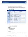
Utilities for the PinPoint-E . . . . . . . . . . . . . . . . . . . . . . . . . . . . . . . . . . . 10
AceView . . . . . . . . . . . . . . . . . . . . . . . . . . . . . . . . . . . . . . . . . . . . . . . . . . . . . . . . . . . . . .10
Wireless Ace . . . . . . . . . . . . . . . . . . . . . . . . . . . . . . . . . . . . . . . . . . . . . . . . . . . . . . . . . . . 11
AceNet . . . . . . . . . . . . . . . . . . . . . . . . . . . . . . . . . . . . . . . . . . . . . . . . . . . . . . . . . . . . . . . .12
Modem Doctor. . . . . . . . . . . . . . . . . . . . . . . . . . . . . . . . . . . . . . . . . . . . . . . . . . . . . . . . . .13
IP Manager and DNS . . . . . . . . . . . . . . . . . . . . . . . . . . . . . . . . . . . . . . . . 15
Fully Qualified Domain Name . . . . . . . . . . . . . . . . . . . . . . . . . . . . . . . . . . . . . . . . . . . . .16
Dynamic Names . . . . . . . . . . . . . . . . . . . . . . . . . . . . . . . . . . . . . . . . . . . . . . . . . . . . . . . .17
Configuring the PinPoint-E for IP Manager and a Dynamic IP Domain Name . . . . . . . .17
Data Usage for IP Manager Server Updates . . . . . . . . . . . . . . . . . . . . . . . . . . . . . . . . . . . . . . 18
Eairlink.com . . . . . . . . . . . . . . . . . . . . . . . . . . . . . . . . . . . . . . . . . . . . . . . . . . . . . . . . . . . . . . . 18
DNS: Using Names Instead of IP addresses . . . . . . . . . . . . . . . . . . . . . . . . . . . . . . . . . . .19
Configuring DNS . . . . . . . . . . . . . . . . . . . . . . . . . . . . . . . . . . . . . . . . . . . . . . . . . . . . . . . . . . . 19
Data Communication and Host Modes . . . . . . . . . . . . . . . . . . . . . . . . . 21
AT Mode . . . . . . . . . . . . . . . . . . . . . . . . . . . . . . . . . . . . . . . . . . . . . . . . . . . . . . . . . . . . . .22
PassThru Mode . . . . . . . . . . . . . . . . . . . . . . . . . . . . . . . . . . . . . . . . . . . . . . . . . . . . . . . . .22
TelnetMode . . . . . . . . . . . . . . . . . . . . . . . . . . . . . . . . . . . . . . . . . . . . . . . . . . . . . . . . . . . .23
PPP Mode . . . . . . . . . . . . . . . . . . . . . . . . . . . . . . . . . . . . . . . . . . . . . . . . . . . . . . . . . . . . .24
Slip Mode . . . . . . . . . . . . . . . . . . . . . . . . . . . . . . . . . . . . . . . . . . . . . . . . . . . . . . . . . . . . .25
UDP Pad . . . . . . . . . . . . . . . . . . . . . . . . . . . . . . . . . . . . . . . . . . . . . . . . . . . . . . . . . . . . . .25
Reliable UDP . . . . . . . . . . . . . . . . . . . . . . . . . . . . . . . . . . . . . . . . . . . . . . . . . . . . . . . . . . . . . . 26
UDP Auto Answer. . . . . . . . . . . . . . . . . . . . . . . . . . . . . . . . . . . . . . . . . . . . . . . . . . . . . . . . . . . 26
PinPoint-E EDGE/GPRS - User Guide, version 2.32
iii
Contents
UDP Multicast Mode . . . . . . . . . . . . . . . . . . . . . . . . . . . . . . . . . . . . . . . . . . . . . . . . . . . . . . . . 27
TCP PAD . . . . . . . . . . . . . . . . . . . . . . . . . . . . . . . . . . . . . . . . . . . . . . . . . . . . . . . . . . . . . .27
TCP Auto Answer . . . . . . . . . . . . . . . . . . . . . . . . . . . . . . . . . . . . . . . . . . . . . . . . . . . . . . . . . . . 28
Hybrid Modes . . . . . . . . . . . . . . . . . . . . . . . . . . . . . . . . . . . . . . . . . . . . . . . . . . . . . . . . . .28
Public and Private Mode . . . . . . . . . . . . . . . . . . . . . . . . . . . . . . . . . . . . . . . . . . . . . . . . . .28
Internal DHCP Server . . . . . . . . . . . . . . . . . . . . . . . . . . . . . . . . . . . . . . . . . . . . . . . . . . . .29
DHCP and Routing. . . . . . . . . . . . . . . . . . . . . . . . . . . . . . . . . . . . . . . . . . . . . . . . . . . . . . . . . . 29
DHCP in the PinPoint-E using Public Mode . . . . . . . . . . . . . . . . . . . . . . . . . . . . . . . . . . . . . 30
PPPoE with DHCP . . . . . . . . . . . . . . . . . . . . . . . . . . . . . . . . . . . . . . . . . . . . . . . . . . . . . . . . . 30
The AirLink Modem as a Gateway . . . . . . . . . . . . . . . . . . . . . . . . . . . . . . . . . . . . . . . . . .30
Keepalive . . . . . . . . . . . . . . . . . . . . . . . . . . . . . . . . . . . . . . . . . . . . . . . . . . . . . . . . . . . . . .31
Configuring Keepalive . . . . . . . . . . . . . . . . . . . . . . . . . . . . . . . . . . . . . . . . . . . . . . . . . . . . . . . 31
Data usage using Keepalive . . . . . . . . . . . . . . . . . . . . . . . . . . . . . . . . . . . . . . . . . . . . . . . . . . . 31
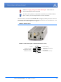
External Inputs & Power Control . . . . . . . . . . . . . . . . . . . . . . . . . . . . . . 32
Capturing Events via External Inputs . . . . . . . . . . . . . . . . . . . . . . . . . . . . . . . . . . . . . . . .32
Setting the DTR and RTS . . . . . . . . . . . . . . . . . . . . . . . . . . . . . . . . . . . . . . . . . . . . . . . . . . . . . 32
Connecting to the Serial Port . . . . . . . . . . . . . . . . . . . . . . . . . . . . . . . . . . . . . . . . . . . . . . . . . 32
Power Modes . . . . . . . . . . . . . . . . . . . . . . . . . . . . . . . . . . . . . . . . . . . . . . . . . . . . . . . . . . .34
Power Effect on Modem State . . . . . . . . . . . . . . . . . . . . . . . . . . . . . . . . . . . . . . . . . . . . . . . . . 35
Global Positioning System (GPS) . . . . . . . . . . . . . . . . . . . . . . . . . . . . . . 36
GPS Overview . . . . . . . . . . . . . . . . . . . . . . . . . . . . . . . . . . . . . . . . . . . . . . . . . . . . . . . . .36
AirLink Remote Access Protocol (RAP) . . . . . . . . . . . . . . . . . . . . . . . . . . . . . . . . . . . . . . . . .
National Marine Electronics Association (NMEA) . . . . . . . . . . . . . . . . . . . . . . . . . . . . . . . . .
Trimble ASCII Interface Protocol (TAIP) . . . . . . . . . . . . . . . . . . . . . . . . . . . . . . . . . . . . . . . .
Datum . . . . . . . . . . . . . . . . . . . . . . . . . . . . . . . . . . . . . . . . . . . . . . . . . . . . . . . . . . . . . . . . . . . .
37
37
37
38
Real-Time Clock Sync . . . . . . . . . . . . . . . . . . . . . . . . . . . . . . . . . . . . . . . . . . . . . . . . . . .38
TCP GPS Polling . . . . . . . . . . . . . . . . . . . . . . . . . . . . . . . . . . . . . . . . . . . . . . . . . . . . . . . .38
Configuring the PinPoint-E for GPS . . . . . . . . . . . . . . . . . . . . . . . . . . . . . . . . . . . . . . . .39
Before you Begin to Configure GPS . . . . . . . . . . . . . . . . . . . . . . . . . . . . . . . . . . . . . . . . . . . . .
Configuring the Datum . . . . . . . . . . . . . . . . . . . . . . . . . . . . . . . . . . . . . . . . . . . . . . . . . . . . . .
Over-The-Air (Remote) Host . . . . . . . . . . . . . . . . . . . . . . . . . . . . . . . . . . . . . . . . . . . . . . . . . .
Local Host. . . . . . . . . . . . . . . . . . . . . . . . . . . . . . . . . . . . . . . . . . . . . . . . . . . . . . . . . . . . . . . . .
TCP GPS Report Polling . . . . . . . . . . . . . . . . . . . . . . . . . . . . . . . . . . . . . . . . . . . . . . . . . . . . .
Report Types . . . . . . . . . . . . . . . . . . . . . . . . . . . . . . . . . . . . . . . . . . . . . . . . . . . . . . . . . . . . . .
Sending Reports Automatically . . . . . . . . . . . . . . . . . . . . . . . . . . . . . . . . . . . . . . . . . . . . . . . .
39
39
39
40
40
40
41
RAP Configuration . . . . . . . . . . . . . . . . . . . . . . . . . . . . . . . . . . . . . . . . . . . . . . . . . . . . . .42
RAP Reports Over-The-Air (Remote) . . . . . . . . . . . . . . . . . . . . . . . . . . . . . . . . . . . . . . . . . . . 42
RAP Reports over a Local Connection (PPP or SLIP) . . . . . . . . . . . . . . . . . . . . . . . . . . . . . . 43
RAP Message format . . . . . . . . . . . . . . . . . . . . . . . . . . . . . . . . . . . . . . . . . . . . . . . . . . . . . . . . 43
Additional RAP Features . . . . . . . . . . . . . . . . . . . . . . . . . . . . . . . . . . . . . . . . . . . . . . . . .44
Device ID . . . . . . . . . . . . . . . . . . . . . . . . . . . . . . . . . . . . . . . . . . . . . . . . . . . . . . . . . . . . . . . . . 44
Odometer Data in Reports . . . . . . . . . . . . . . . . . . . . . . . . . . . . . . . . . . . . . . . . . . . . . . . . . . . . 45
COM1000 Event Reports . . . . . . . . . . . . . . . . . . . . . . . . . . . . . . . . . . . . . . . . . . . . . . . . . . . . . 46
Store and Forward for RAP . . . . . . . . . . . . . . . . . . . . . . . . . . . . . . . . . . . . . . . . . . . . . . .46
Store and Forward Reliable Mode . . . . . . . . . . . . . . . . . . . . . . . . . . . . . . . . . . . . . . . . . . . . . . 47
Sending Reports . . . . . . . . . . . . . . . . . . . . . . . . . . . . . . . . . . . . . . . . . . . . . . . . . . . . . . . . . . . . 47
Flush on Event . . . . . . . . . . . . . . . . . . . . . . . . . . . . . . . . . . . . . . . . . . . . . . . . . . . . . . . . . . . . . 48
PinPoint-E EDGE/GPRS - User Guide, version 2.32
iv
Contents
NMEA Configuration . . . . . . . . . . . . . . . . . . . . . . . . . . . . . . . . . . . . . . . . . . . . . . . . . . . .48
Streaming NMEA Messages over the local port . . . . . . . . . . . . . . . . . . . . . . . . . . . . . . . . . . . 48
NMEA Messages Over-The-Air (Remote) . . . . . . . . . . . . . . . . . . . . . . . . . . . . . . . . . . . . . . . . 49
NMEA Messages over a Local Connection (PPP) . . . . . . . . . . . . . . . . . . . . . . . . . . . . . . . . . 49
TAIP Emulation Configuration . . . . . . . . . . . . . . . . . . . . . . . . . . . . . . . . . . . . . . . . . . . . .50
TAIP Messages Over-the-Air (Remote) . . . . . . . . . . . . . . . . . . . . . . . . . . . . . . . . . . . . . . . . . .
TAIP Messages over a Local Connection (PPP) . . . . . . . . . . . . . . . . . . . . . . . . . . . . . . . . . . .
Sending Unsolicited TAIP Messages over a Local Connection (PPP). . . . . . . . . . . . . . . . . . .
Using TAIP Command Emulation . . . . . . . . . . . . . . . . . . . . . . . . . . . . . . . . . . . . . . . . . . . . . .
TAIP ID . . . . . . . . . . . . . . . . . . . . . . . . . . . . . . . . . . . . . . . . . . . . . . . . . . . . . . . . . . . . . . . . . . .
Supported TAIP Commands . . . . . . . . . . . . . . . . . . . . . . . . . . . . . . . . . . . . . . . . . . . . . . . . . . .
50
51
51
52
52
52
Hardware Installation . . . . . . . . . . . . . . . . . . . . . . . . . . . . . . . . . . . . . . . 54
Connecting the Antennas. . . . . . . . . . . . . . . . . . . . . . . . . . . . . . . . . . . . . . . . . . . . . . . . . .54
Connecting Power . . . . . . . . . . . . . . . . . . . . . . . . . . . . . . . . . . . . . . . . . . . . . . . . . . . . . . .55
Connecting the PinPoint-E to a computer or other device . . . . . . . . . . . . . . . . . . . . . . . .55
PinPoint-E Indicator Lights . . . . . . . . . . . . . . . . . . . . . . . . . . . . . . . . . . . . . . . . . . . . . . .55
Light Patterns . . . . . . . . . . . . . . . . . . . . . . . . . . . . . . . . . . . . . . . . . . . . . . . . . . . . . . . . . . . . . . 56
Modem Placement . . . . . . . . . . . . . . . . . . . . . . . . . . . . . . . . . . . . . . . . . 57
Optional Mounting Kit . . . . . . . . . . . . . . . . . . . . . . . . . . . . . . . . . . . . . . . . . . . . . . . . . . . . . . . 57
GPS Antenna Location . . . . . . . . . . . . . . . . . . . . . . . . . . . . . . . . . . . . . . . . . . . . . . . . . . .59
Specifications for the PinPoint-E EDGE/GPRS . . . . . . . . . . . . . . . . . . . . 60
Physical Characteristics: . . . . . . . . . . . . . . . . . . . . . . . . . . . . . . . . . . . . . . . . . . . . . . . . . . . . .
Environmental: . . . . . . . . . . . . . . . . . . . . . . . . . . . . . . . . . . . . . . . . . . . . . . . . . . . . . . . . . . . .
Power Management: . . . . . . . . . . . . . . . . . . . . . . . . . . . . . . . . . . . . . . . . . . . . . . . . . . . . . . . .
Power consumption . . . . . . . . . . . . . . . . . . . . . . . . . . . . . . . . . . . . . . . . . . . . . . . . . . . . . . . . .
Serial Port Pinouts . . . . . . . . . . . . . . . . . . . . . . . . . . . . . . . . . . . . . . . . . . . . . . . . . . . . . . . . . .
60
60
61
61
61
AT Commands . . . . . . . . . . . . . . . . . . . . . . . . . . . . . . . . . . . . . . . . . . . . . 62
Using Wireless Ace . . . . . . . . . . . . . . . . . . . . . . . . . . . . . . . . . . . . . . . . . . . . . . . . . . . . . .62
Using Telnet Terminal Emulation . . . . . . . . . . . . . . . . . . . . . . . . . . . . . . . . . . . . . . . . . . .64
Direct Serial Connection . . . . . . . . . . . . . . . . . . . . . . . . . . . . . . . . . . . . . . . . . . . . . . . . . .65
Using AT Commands with a Terminal Application . . . . . . . . . . . . . . . . . . . . . . . . . . . . .66
AT Command Listing . . . . . . . . . . . . . . . . . . . . . . . . . . . . . . . . . . . . . . . . . . . . . . . . . . . .68
Information and Status . . . . . . . . . . . . . . . . . . . . . . . . . . . . . . . . . . . . . . . . . . . . . . . . . . . . . . . 70
Misc (Miscellaneous) . . . . . . . . . . . . . . . . . . . . . . . . . . . . . . . . . . . . . . . . . . . . . . . . . . . . . . . . 76
Serial. . . . . . . . . . . . . . . . . . . . . . . . . . . . . . . . . . . . . . . . . . . . . . . . . . . . . . . . . . . . . . . . . . . . . 79
TCP . . . . . . . . . . . . . . . . . . . . . . . . . . . . . . . . . . . . . . . . . . . . . . . . . . . . . . . . . . . . . . . . . . . . . . 86
UDP . . . . . . . . . . . . . . . . . . . . . . . . . . . . . . . . . . . . . . . . . . . . . . . . . . . . . . . . . . . . . . . . . . . . . 88
DNS. . . . . . . . . . . . . . . . . . . . . . . . . . . . . . . . . . . . . . . . . . . . . . . . . . . . . . . . . . . . . . . . . . . . . . 91
Dynamic IP . . . . . . . . . . . . . . . . . . . . . . . . . . . . . . . . . . . . . . . . . . . . . . . . . . . . . . . . . . . . . . . . 92
PPP/Ethernet . . . . . . . . . . . . . . . . . . . . . . . . . . . . . . . . . . . . . . . . . . . . . . . . . . . . . . . . . . . . . . 94
PassThru . . . . . . . . . . . . . . . . . . . . . . . . . . . . . . . . . . . . . . . . . . . . . . . . . . . . . . . . . . . . . . . . . . 96
SMTP (including SMS) . . . . . . . . . . . . . . . . . . . . . . . . . . . . . . . . . . . . . . . . . . . . . . . . . . . . . . . 98
Other . . . . . . . . . . . . . . . . . . . . . . . . . . . . . . . . . . . . . . . . . . . . . . . . . . . . . . . . . . . . . . . . . . . . 100
Low Power . . . . . . . . . . . . . . . . . . . . . . . . . . . . . . . . . . . . . . . . . . . . . . . . . . . . . . . . . . . . . . . 103
Friends . . . . . . . . . . . . . . . . . . . . . . . . . . . . . . . . . . . . . . . . . . . . . . . . . . . . . . . . . . . . . . . . . . 105
Logging . . . . . . . . . . . . . . . . . . . . . . . . . . . . . . . . . . . . . . . . . . . . . . . . . . . . . . . . . . . . . . . . . . 107
PinPoint . . . . . . . . . . . . . . . . . . . . . . . . . . . . . . . . . . . . . . . . . . . . . . . . . . . . . . . . . . . . . . . . . 109
PinPoint-E EDGE/GPRS - User Guide, version 2.32
v
Contents
EDGE/HSDPA . . . . . . . . . . . . . . . . . . . . . . . . . . . . . . . . . . . . . . . . . . . . . . . . . . . . . . . . . . . . 116
PPPoE: Point to Point Protocol over Ethernet . . . . . . . . . . . . . . . . . . 117
PPPoE (PPP over Ethernet) Configuration . . . . . . . . . . . . . . . . . . . . . . . . . . . . . . . . . . . 117
Configuring your PinPoint-E for PPPoE . . . . . . . . . . . . . . . . . . . . . . . . . . . . . . . . . . . . . . . 117
Configuring a PPPoE Connection in Windows . . . . . . . . . . . . . . . . . . . . . . . . . . . . . . .120
Connecting to the Internet with PPPoE . . . . . . . . . . . . . . . . . . . . . . . . . . . . . . . . . . . . . . . . . 125
Configuring your router for PPPoE with the PinPoint-E . . . . . . . . . . . . . . . . . . . . . . . .126
Simple Network Management Protocol (SNMP) . . . . . . . . . . . . . . . . 127
SNMP Overview . . . . . . . . . . . . . . . . . . . . . . . . . . . . . . . . . . . . . . . . . . . . . . . . . . . . . . .127
Management Information Base (MIB) . . . . . . . . . . . . . . . . . . . . . . . . . . . . . . . . . . . . . . . . . . 127
SNMP Traps . . . . . . . . . . . . . . . . . . . . . . . . . . . . . . . . . . . . . . . . . . . . . . . . . . . . . . . . . . . . . . 127
PinPoint-E SNMP Configuration . . . . . . . . . . . . . . . . . . . . . . . . . . . . . . . . . . . . . . . . . .127
Listening Port . . . . . . . . . . . . . . . . . . . . . . . . . . . . . . . . . . . . . . . . . . . . . . . . . . . . . . . . . . . . .
Security Level . . . . . . . . . . . . . . . . . . . . . . . . . . . . . . . . . . . . . . . . . . . . . . . . . . . . . . . . . . . . .
User Name and Password . . . . . . . . . . . . . . . . . . . . . . . . . . . . . . . . . . . . . . . . . . . . . . . . . . .
Trap Destination . . . . . . . . . . . . . . . . . . . . . . . . . . . . . . . . . . . . . . . . . . . . . . . . . . . . . . . . . .
Community String . . . . . . . . . . . . . . . . . . . . . . . . . . . . . . . . . . . . . . . . . . . . . . . . . . . . . . . . . .
128
128
128
129
129
SNMP MIB Definition for AirLink . . . . . . . . . . . . . . . . . . . . . . . . . . . . . . . . . . . . . . . .129
GPS Message Format Streams . . . . . . . . . . . . . . . . . . . . . . . . . . . . . . . 136
NMEA Message Description. . . . . . . . . . . . . . . . . . . . . . . . . . . . . . . . . . . . . . . . . . . . . .136
TAIP Message Description . . . . . . . . . . . . . . . . . . . . . . . . . . . . . . . . . . . . . . . . . . . . . . .138
Warranty Terms and Conditions . . . . . . . . . . . . . . . . . . . . . . . . . . . . . 139
Warranty Terms . . . . . . . . . . . . . . . . . . . . . . . . . . . . . . . . . . . . . . . . . . . . . . . . . . . . . . . .139
Standard Software Warranty . . . . . . . . . . . . . . . . . . . . . . . . . . . . . . . . . . . . . . . . . . . . . . . . .
One Year Standard Equipment Warranty . . . . . . . . . . . . . . . . . . . . . . . . . . . . . . . . . . . . . . . .
Optional Two Year Extended Equipment Warranty . . . . . . . . . . . . . . . . . . . . . . . . . . . . . . . .
Optional Four Year Extended Equipment Warranty . . . . . . . . . . . . . . . . . . . . . . . . . . . . . . .
139
139
139
139
Warranty Conditions . . . . . . . . . . . . . . . . . . . . . . . . . . . . . . . . . . . . . . . . . . . . . . . . . . . .140
Remedy . . . . . . . . . . . . . . . . . . . . . . . . . . . . . . . . . . . . . . . . . . . . . . . . . . . . . . . . . . . . . . . . . .
WARRANTY DISCLAIMER . . . . . . . . . . . . . . . . . . . . . . . . . . . . . . . . . . . . . . . . . . . . . . . . .
LIMITATION OF LIABILITY . . . . . . . . . . . . . . . . . . . . . . . . . . . . . . . . . . . . . . . . . . . . . . . . .
General Conditions . . . . . . . . . . . . . . . . . . . . . . . . . . . . . . . . . . . . . . . . . . . . . . . . . . . . . . . .
140
140
140
141
Frequently Asked Questions and Technical Support . . . . . . . . . . . . . 142
FAQ Topics . . . . . . . . . . . . . . . . . . . . . . . . . . . . . . . . . . . . . . . . . . . . . . . . . . . . . . . . . . .142
Power, Antennas, and Signal Strength . . . . . . . . . . . . . . . . . . . . . . . . . . . . . . . . . . . . . . . . . 143
The PinPoint-E’s IP Addresses and Local Networking . . . . . . . . . . . . . . . . . . . . . . . . . . . . 145
Security for the PinPoint-E . . . . . . . . . . . . . . . . . . . . . . . . . . . . . . . . . . . . . . . . . . . . . . . . . . 148
GPS Features . . . . . . . . . . . . . . . . . . . . . . . . . . . . . . . . . . . . . . . . . . . . . . . . . . . . . . . . . . . . . 149
Third Party Device and Application Support . . . . . . . . . . . . . . . . . . . . . . . . . . . . . . . . . . . . 150
AirLink Technical Support . . . . . . . . . . . . . . . . . . . . . . . . . . . . . . . . . . . . . . . . . . . . . . .151
AirLink Support Web Site . . . . . . . . . . . . . . . . . . . . . . . . . . . . . . . . . . . . . . . . . . . . . . . . . . . . 151
AirLink Documentation and Guides . . . . . . . . . . . . . . . . . . . . . . . . . . . . . . . . . . . . . . . . . . . 151
Contacting Technical Support . . . . . . . . . . . . . . . . . . . . . . . . . . . . . . . . . . . . . . . . . . . . . . . . 151
PinPoint-E EDGE/GPRS - User Guide, version 2.32
vi
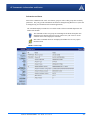
CHAPTER 1
Introduction to PinPoint-E EDGE/GPRS
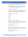
The PinPoint-E's rugged form factor is ideal for industrial and commercial applications that
require real-time communications. The PinPoint-E provides cellular data communications for a
variety of applications, such as public safety, traffic control, traffic metering, transit arrival systems, and more.
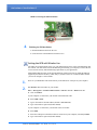
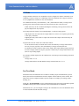
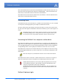
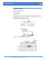
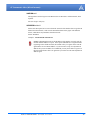
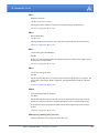
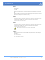
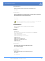
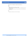
FIGURE 1.
PinPoint-E front and back
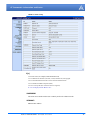
EDGE/GPRS Overview
EDGE (Enhanced Data rates for GSM Evolution) provides end-to-end packet data services with
an enhanced connectivity building on GPRS technology and using the established GSM networks. EDGE provides higher transmission rates and better transmission quality for data than
GPRS. EDGE can carry data at speeds typically up to 384 kbit/s in packet mode.
When EDGE/GPRS is not available, your PinPoint-E will fall-back to GPRS for the connection to
Your Wireless Service Provider to provide continued connectivity.
General Packet Radio Service (GPRS) is packet-switched with many users sharing the same
transmission channel, but only transmitting when they have data to send. This means that the total
available bandwidth can be immediately dedicated to those users who are actually sending at any
given moment, providing higher utilization where users only send or receive data intermittently.
GPRS provides speeds of 30–70 kbps with bursts up to 170 kbps.
PinPoint-E EDGE/GPRS - User Guide, version 2.32
1
Introduction to PinPoint-E EDGE/GPRS
Establishing an Internet Connection
The PinPoint-E uses Your Wireless Service Provider as an ISP (Internet Service Provider) to connect you to the Internet.
Steps of a connection:
1.
When your PinPoint-E is powered on, it automatically searches for cellular service using
EDGE/GPRS.
2.
Your PinPoint-E establishes a PPP (Point to Point Protocol or “dial” up connection) link to
Your Wireless Service Provider’s network, also called registering on the network, and receives
an IP address.
3.
When your PinPoint-E has received its IP address from Your Wireless Service Provider, then
it is ready to allow you to connect to the Internet.
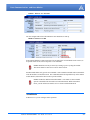
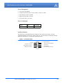
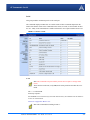
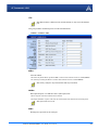
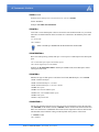
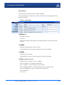
FIGURE 2.
Using the PinPoint-E to connect to the Internet
EDGE/GPRS
Internet
Dynamic vs. Static IP Addresses
As stated above, when your PinPoint-E registers on Your Wireless Service Provider’s network, it
receives an IP address. There are two types of addresses on networks: dynamic and static.
• Dynamic addresses are assigned on a “need to have” basis. Your PinPoint-E might not always
receive the same address each time it connects with Your Wireless Service Provider.
• Static addresses are permanently assigned to a particular account and will always be used
whenever your PinPoint-E connects to the Internet. The IP address will not be given to anyone
else.
Most ISPs (cellular included) use dynamic IP addresses rather than static IP addresses since it
allows them to reuse a smaller number of IP addresses for a large number of customers. A
dynamic IP address is suitable for many common Internet uses, such as web browsing, looking up
PinPoint-E EDGE/GPRS - User Guide, version 2.32
2
Introduction to PinPoint-E EDGE/GPRS
data on another computer system, or other client functions (such as data only being sent out or only
being received after an initial request).
If you need to contact your PinPoint-E, a device connected to the modem, or a host system using
the modem from the Internet, you need to have a known IP (such as one which is static) or domain
name (an IP address which is converted by a DNS server into a word based name). If you have a
dynamic IP address for your modem, you can use a Dynamic DNS service (such as IP Manager,
page 15) to translate your IP address into to a domain name.
Caution: If you want to connect remotely to your PinPoint-E using TCP/IP, the IP
address given to your modem by the network cannot be a private or internal IP
address (such as a) unless you are on the same network or inside that network’s
firewall (such as with frame relay).
Using Your PinPoint-E to Connect to the Internet
In Public Mode, your PinPoint-E will pass the IP address from Your Wireless Service Provider’s
network to your device or computer. In Private Mode, your modem will assign configured, static
local network IP addresses for the modem and your device.
The modem will perform a one-to-one routing for all internet traffic to and from the computer or
other end device.
If you need to have more than one device connected to the Internet through the modem, you will
need to have a router connected to the modem. The modem would provide the one-to-one connection to the router with the router configured to provide a broader NAT service to the other
devices connected to it.
You can connect directly through your PinPoint-E to the Internet using the Ethernet port or use
PPPoE for a password protected connection. For a direct connection, the PinPoint-E features
DHCP (enabled by default) so you don’t need to worry about setting up an IP address on your
computer. DHCP works with both Private and Public Modes.
Common Uses for the PinPoint-E
The PinPoint-E’s rugged construction and cellular connection make it ideal for use in remote and/
or industrial locations.
Because of its GPS capabilities, the PinPoint-E is ideal for vehicle tracking and other situations
where mapping a moving object is as important as connecting to a network.
PinPoint-E EDGE/GPRS - User Guide, version 2.32
3
Introduction to PinPoint-E EDGE/GPRS
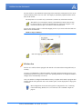
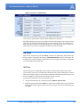
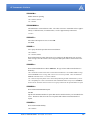
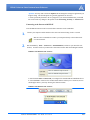
FIGURE 3.
Vehicle Tracking and Mobile Internet Access
PinPoint-E EDGE/GPRS - User Guide, version 2.32
4
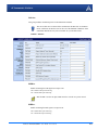
CHAPTER 2
Activation of the PinPoint-E
To install the SIM, you will only need a small phillips head screw driver.
1.
Opening the Case
a. Unplug the PinPoint-E’s power and all cables.
b. Using a small phillips head screw driver, remove the screws on the back of the PinPoint-E.
c. Slide the casing off of the PinPoint-E and set it aside.
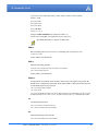
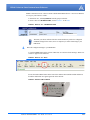
FIGURE 1.
2.
PinPoint-E back
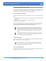
Ejecting the SIM tray
a. Using the tip of a PDA stylus, an unbent paperclip, or other slim blunt item press the yellow
button of the SIM tray. On the PinPoint-E, the button is between two boards.
PinPoint-E EDGE/GPRS - User Guide, version 2.32
5
Activation of the PinPoint-E
FIGURE 2.
Tray button: PinPoint-E
b. Slide the tray out of the slot.
FIGURE 3.
3.
Empty SIM Tray
Inserting the SIM
a. Place the SIM into the tray and gently press to click it into place.
FIGURE 4.
SIM Tray with a SIM
The SIM may be a different color than this
example.
b. Slide the tray back into the modem and gently press to click it into place.
Note: The top of the card faces the the bottom of the modem.
PinPoint-E EDGE/GPRS - User Guide, version 2.32
6
Activation of the PinPoint-E
FIGURE 5.
4.
Inserting the SIM: PinPoint-E
Finishing the SIM installation
a. Slide the PinPoint-E back into the case.
b. Secure the back of the PinPoint-E with the screws.
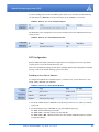
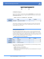
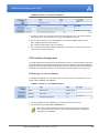
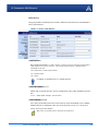
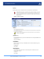
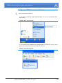
Setting the APN with Wireless Ace
The APN (Access Point Name) is the way your modem knows how it will be communicating with
the network. The APN allows custom IP addressing and tailoring your company's wireless IP solution to meet the security and IP addressing requirements of your applications.
Most EDGE/GPRS accounts use the default addressing solution of Private or Public IP addresses
supplied by the Internet and Proxy APNs. Only if you have a Static or Custom IP address should
you need to configure a custom APNs.
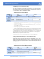
1.
Power on your PinPoint-E and connect directly to the Ethernet or serial port on your computer.
2.
Start Wireless Ace and connect to your modem:
Start > All Programs > AirLink Communications > Wireless Ace 3G > Wireless Ace 3G
A.
Click on Connect.
If your computer is connected to your modem with an Ethernet cable:
B.
Select UDP or TCP.
C.
Type in the modem’s local IP address (default is 192.168.13.31).
D.
Type in the modem’s password (default 12345).
If your computer is connected to your modem with a serial cable:
B.
Select PPP.
C.
Select the COM port to which the modem is connected on your computer (commonly COM1).
D.
Type in the modem’s password (default 12345).
PinPoint-E EDGE/GPRS - User Guide, version 2.32
7
Activation of the PinPoint-E
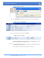
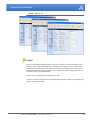
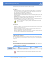
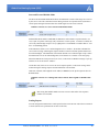
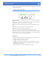
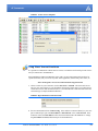
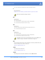
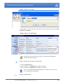
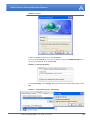
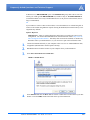
FIGURE 6.
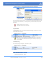
3.
Select EDGE/HSDPA from the menu on the left side of Wireless Ace (under “Groups”).
FIGURE 7.
4.
Wireless Ace: Connect
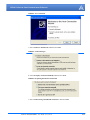
Wireless Ace: EDGE/HSDPA
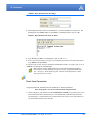
Type in the APN in the new value field of *NETAPN.
FIGURE 8.
Wireless Ace: *NETAPN
Internet
For most EDGE/GPRS accounts the APN for your modem will be Internet or Proxy. Consult
with your account representative on which APN to use.
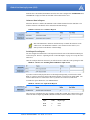
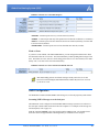
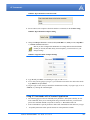
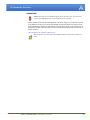
Optional
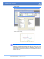
If you need to configure your modem for a custom APN, after entering the APN, there is additional information you will need to enter.
A.
Select Misc from the menu on the left side under the Common group.
PinPoint-E EDGE/GPRS - User Guide, version 2.32
8
Activation of the PinPoint-E
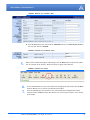
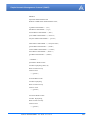
FIGURE 9.
B.
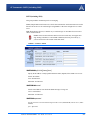
Wireless Ace: Common - Misc
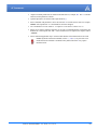
Enter the NAI into the new value field for *NETUID and enter your network password into
the new value field for *NETPW.
FIGURE 10.
Wireless Ace: Common - Misc
[ NAI ]
[ Password ]
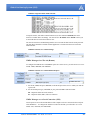
5.
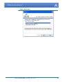
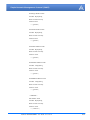
When you have finished entering the APN settings, click the Write button on the tool bar of Wireless Ace and wait for the message “Write Successful” to appear in the status bar.
FIGURE 11.
6.
7.
Wireless Ace: Write
It is recommended that you reset your modem after configuring the APN. Either click the Reset
button in Wireless Ace or press the reset button on the modem.
On lui recommande que vous remettiez à zéro votre modem après configuration de l'APN.
Cliquer le bouton de Reset (remise) dans Wireless Ace ou serrer pour remettre à zéro le bouton
sur le modem.
PinPoint-E EDGE/GPRS - User Guide, version 2.32
9
CHAPTER 3
Utilities for the PinPoint-E
AirLink offers a suite of utilities to optimize your PinPoint-E’s performance, allowing you to
remotely view status and make changes to the configuration as needed.
• AceView
• AceNet
• Wireless Ace
• Modem Doctor
This section of the PinPoint-E User Guide covers basic information about these utilities. For additional information on a specific application and how to use it, please refer to the user guide for the
specific utility.
AirLink modem utilities, except AceNet, are free of charge to those who own AirLink modems.
You can download the applications and their user guides from the AirLink web site: http://www.airlink.com/support. Contact your dealer or AirLink representative for information on AceNet.
Note: AceView, Wireless Ace, and AceNet require the Microsoft .NET Framework
v. 1.1 and Microsoft Windows 98, Windows 2000, Windows XP, or later. You can
obtain the Microsoft .NET Framework from Microsoft at: http://
www.microsoft.com/.
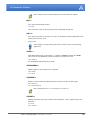
AceView
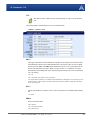
AceView is a low-profile monitoring tool to view the status of your AirLink PinPoint-E and display
network status, IP address, RSSI strength, and other basic connection information.
FIGURE 1.
AceView
PinPoint-E EDGE/GPRS - User Guide, version 2.32
10
Utilities for the PinPoint-E
You can connect to your PinPoint-E locally using a DUN connection or Ethernet across a LAN or
connected directly with a cross over cable. The display is dynamically updated with the current
status of the modem.
The GPS features are available only for PinPoint X, PinPoint-E, and PinPoint modems.
Note: While you can use PPP to connect to the PinPoint-E, Internet data will only
be routed to a device connected to the Ethernet port. If the same computer is connected to the Ethernet port, it can interfere with communication.
AceView also features a link to a web-based mapping service so you can see where the GPS coordinates locate the PinPoint-E.
FIGURE 2.
Map Coordinates
Note: The mapping feature requires an Internet connection.
Wireless Ace
Wireless Ace enables modems equipped with ALEOS to be monitored and configured locally or
remotely.
As long as your PinPoint-E is online and publicly accessible, support personnel can access your
modem from anywhere at any time to see how it is operating and how it is configured. Parameter
changes can be made instantly over-the-air.
Once your modem is configured and installed correctly, a template can be made to program other
modems with the same parameter values. This enables quick, accurate deployment of large pools
of modems.
Most configuration screen shots in this guide are using Wireless Ace. Connecting
to the modem using Wireless Ace is covered in the “AT Commands” chapter on
page 62.
PinPoint-E EDGE/GPRS - User Guide, version 2.32
11
Utilities for the PinPoint-E
FIGURE 3.
Wireless Ace
AceNet
AceNet is a full featured application that you can use to monitor several AirLink modems at the
same time, use a template from Wireless Ace to change the configuration in all of them simultaneously, keep the modems up-to-date with the latest firmware by updating them over the air, periodically log the modems’ Status parameters, and even graphically chart the logged parameters to
see trends or other over time information.
AceNet’s remote connections use TCP/IP, UDP, or SMS.
AceNet is a separate product which can be purchased from AirLink. Contact your AirLink representative for more information.
PinPoint-E EDGE/GPRS - User Guide, version 2.32
12
Utilities for the PinPoint-E
FIGURE 4.
AceNet
FIGURE 5.
AceNet Charting
Modem Doctor
Modem Doctor is a troubleshooting and diagnostics utility. This utility will allow you to get a log
file of the PinPoint-E activity which you can then send to AirLink support, erase the current configuration completely, and temporarily set the PinPoint-E to a known configuration to aid in trouble shooting (SOS mode).
PinPoint-E EDGE/GPRS - User Guide, version 2.32
13
Utilities for the PinPoint-E
FIGURE 6.
Modem Doctor
PinPoint-E EDGE/GPRS - User Guide, version 2.32
14
CHAPTER 4
IP Manager and DNS
If you have a fleet of AirLink modems or even if you only have one, it can be difficult to keep track
of the current IP addresses, especially if the addresses aren’t static but change every time the
modems connect to Your Wireless Service Provider. If you need to connect to a modem, or the
device behind it, it is so much easier when you have a domain name (car54.mydomain.com, where
are you?).
Reasons to contact the modem and/or the connected device:
• Contacting a surveillance camera to download logs or survey a specific area.
• Updating advertisements to be displayed in a cab.
• Monitoring and troubleshooting the status of the modem itself without needing to bring it in or
go out to it.
A dynamic IP address is suitable for many Internet activities such as web browsing, looking up data
on another computer system, data only being sent out, or data only being received after an initial
request (also called Mobile Originated). However, if you need to contact your PinPoint-E directly,
a device connected to the modem, or a host system using your PinPoint-E (also called Mobile Terminated), a dynamic IP won’t give you a reliable address to contact (since it may have changed
since the last time it was assigned).
Domain names are often only connected to static IP addresses because of the way most domain
name (DNS) servers are set-up. Dynamic DNS servers require notification of IP Address changes
so they can update their DNS records and link a dynamic IP address to the correct name.
• Dynamic IP addresses are granted only when your PinPoint-E is connected and can change each
time the modem reconnects to the network.
• Static IP addresses are granted the same address every time your PinPoint-E is connected and
are not in use when your PinPoint-E is not connected.
Since many cellular providers, like wire-based ISPs, do not offer static IP addresses or static
address accounts cost a premium vs. dynamic accounts, AirLink developed IP Manager to work
with a Dynamic DNS server to receive notification from AirLink modems to translate the modem’s
dynamic IP address to a fully qualified domain name. Thus, you can contact your PinPoint-E
directly from the Internet using a domain name.
PinPoint-E EDGE/GPRS - User Guide, version 2.32
15
IP Manager and DNS
Fully Qualified Domain Name
A domain name is a name of a server or device on the Internet which is associated with an IP
address. Similar to how the street address of your house is one way to contact you and your phone
number is another, both the IP address and the domain name can be used to contact a server or
device on the Internet. While contacting you at your house address or with your phone number
employ different methods, using a domain name instead of the IP address actually uses the same
method, just a word based name is commonly easier to remember for most people than a string of
numbers.
Understanding the parts of a domain name can help to understand how IP Manager works and what
you need to be able to configure the modem. A fully qualified domain name (FQDN) generally has
several parts.
• Top Level Domain (TLD): The TLD is the ending suffix for a domain name (.com, .net, .org,
etc.)
• Country Code Top Level Domain (ccTLD): This suffix is often used after the TLD for most
countries except the US (.ca, .uk, .au, etc.)
• Domain name: This is the name registered with ICANN (Internet Corporation for Assigned
Names and Numbers) or the registry for a the country of the ccTLD (i.e. if a domain is part of
the .ca TLD, it would be registered with the Canadian domain registry). It is necessary to have
a name registered before it can be used.
• Sub-domain or server name: A domain name can have many sub-domain or server names
associated with it. Sub-domains need to be registered with the domain, but do not need to be
registered with ICANN or any other registry. It is the responsibility of a domain to keep track
of its own subs.
car54.mydomain.com
• .com is the TLD
• mydomain is the domain (usually noted as mydomain.com since the domain is specific to the
TLD)
• car54 is the subdomain or server name associated with the device, computer, or modem registered with mydomain.com
car54.mydomain.com.ca
This would be the same as above, but with the addition of the country code. In this example, the
country code (.ca) is for Canada.
A URL (Universal Resource Locator) is different from a domain name in that it
also indicates information on the protocol used by a web browser to contact that
address, such as http://www.airlink.com. www.airlink.com is a fully qualified
domain name, but the http://, the protocol identifier, is what makes the whole thing
a URL.
PinPoint-E EDGE/GPRS - User Guide, version 2.32
16
IP Manager and DNS
Dynamic Names
When an IP address is not expected to change, the DNS server can indicate to all queries that the
address can be cached and not looked up for a long period of time. Dynamic DNS servers, conversely, have a short caching period for the domain information to prevent other Internet sites or
queries from using the old information. Since the IP address of a modem with a dynamic account
can change frequently, if the old information was used (such as with a DNS server which indicates
the address can be cached for a long period of time) when the IP address changed, the domain
would no longer point to the new and correct IP address of the modem.
If your PinPoint-E is configured for Dynamic IP, when it first connects to the Internet, it sends a IP
change notification to IP Manager. IP Manger will acknowledge the change and update the
Dynamic DNS server. The new IP address will then be the address for your PinPoint-E’s configured name.
Once your PinPoint-E’s IP address has been updated in IP Manager, it can be contacted via name.
If the IP address is needed, you can use the domain name to determine the IP address.
Note: The fully qualified domain name of your PinPoint-E will be a subdomain of
the domain used by the IP Manager server.
Configuring the PinPoint-E for IP Manager and a Dynamic IP
Domain Name
To configure the Dynamic IP settings in your PinPoint-E so that it will use IP Manager, you can use
Wireless Ace or a terminal application to enter the commands (page 62).
To configure your AirLink modem to be addressed by name, the modem needs to have 4 elements
configured. You can configure a second dynamic server as a backup, secondary, or alternate server.
In Wireless Ace, select Dynamic IP.
FIGURE 1.
Wireless Ace: Dynamic IP
car54-2007
eairlink.com
edns2.eairlink.com
eairlink.com
PinPoint-E EDGE/GPRS - User Guide, version 2.32
17
IP Manager and DNS
*MODEMNAME: The name you want for the modem.
*DOMAIN: The domain name to be used by the modem.
*IPMANAGER1 and *IPMANAGER2: The IP address or domain name of the dynamic DNS
server which is running IP Manager.
Note: To use the name here instead of the IP, you need to have DNS set up in your
PinPoint-E (page 19).
*IPMGRUPDATE1 and *IPMGRUPDATE2: How often, in minutes, you want the address
sent to IP Manager. If this is set to zero, the modem will only send an update if the IP address
changes (example, if your PinPoint-E modem is reset or is assigned a different IP address).
*IPMGRKEY1 and *IPMGRKEY2: User defined password key which is used instead of AirLink secret key when using an IP Manager server other than the one provided by AirLink.
Restrictions for Modem Name
For the Modem Name, you should use something which is unique but also easy to remember. Your
company name or the intended function of the modem are recommended. If you have more than
one modem and want to name them the same, you can append a number for each. Since it is an
Internet domain name, there are some restrictions for the name.
•
•
•
•
Must begin with a letter or number
Can include a hyphen (-)
Cannot contain spaces
Must be no longer than 20 characters total
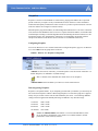
Data Usage for IP Manager Server Updates
The IP Manager update is a small packet sent to the server with a response sent back to the modem.
If you have *IPMGRUPDATE1 or *IPMGRUPDATE2 set to any number but zero, the modem
will send the update not only when it receives a new IP address but at the time interval as well. The
data traffic could be billed by your carrier.
Each update is a total of 68 bytes from the modem with a 50 byte total response from the server for
a round trip update of 118 bytes.
interval
(minutes)
total bytes per
day (24 hours)
interval
(minutes)
total bytes per
day (24 hours)
10
16992 bytes
60
2832 bytes
30
5664 bytes
500
339.84 bytes
Eairlink.com
As a service, Airlink maintains a IP Manager servers which can be used for any AirLink modem.
• *DOMAIN: eairlink.com
• *IPMANAGER1 : edns2.eairlink.com
• *IPMANAGER2 : eairlink.com
PinPoint-E EDGE/GPRS - User Guide, version 2.32
18
IP Manager and DNS
Note: The IP Manager service from AirLink is currently not a guaranteed service
though every effort is made to keep it operational 24/7.
When using AirLink’s IP Manager servers, since there are many AirLink modems
using the service, it is even more imperative to have a unique name for your
modem.
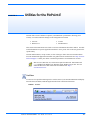
DNS: Using Names Instead of IP addresses
The PinPoint-E has the ability to query DNS servers in order to translate domain names into IP
addresses. This allows you to use domain names in place of IP addresses for most of the configuration options requiring IP addresses. This is important if your PinPoint-E will need to contact
another modem or other device that has a domain name but an unknown or dynamic IP address
(such as another remote PinPoint-E using IP Manager).
Configuring DNS
Generally, when your PinPoint-E receives its IP address from Your Wireless Service Provider, it
will also receive Your Wireless Service Provider’s DNS servers to use for resolving (or translating)
names to IP addresses which it will automatically configure in the modem settings. Unless your
PinPoint-E will be used on a network with other modems or devices which have names internal to
the local network or frequently changing IP addresses, the DNS servers provided by Your Wireless
Service Provider should be all you need.
If the PinPoint-E will be communicating with a device that has a domain name but changes its IP
address frequently (such as another AirLink modem using IP Manager) or is on a network where
devices are accessed by names rather than IP addresses, you will want to put in an alternate DNS
(*DNSUSER) where that domain is updated, such as the IP Manager server the remote modem is
using or the listing of IP addresses to names is kept.
FIGURE 2.
Wireless Ace: DNS
*DNS1 and *DNS2 - The primary and secondary DNS servers set by Your Wireless Service
Provider when your PinPoint-E gets its IP address.
*DNSUSER - Set this, if desired, to an additional DNS server to query first before the primary
or secondary (just as a hosts file is queried first on a computer). If *DNSUSER is set to 0.0.0.0,
it will be ignored.
*DNSUPDATE - This command sets how often you want DNS Updates to be requested. Otherwise the PinPoint-E will only send updates when it is reset, powered up, or the IP address is
granted by network changes.
PinPoint-E EDGE/GPRS - User Guide, version 2.32
19
IP Manager and DNS
Note: If you will be using your PinPoint-E to communicate with another AirLink
modem and both are using IP Manager to translate dynamic IP addresses to
domain names, it is recommended that you set *DNSUSER to the IP address for
IP Manager. IP Manager’s updates occur more frequently than Your Wireless Service Provider’s DNS servers decreasing the time between IP address change and
address resolution. Likewise, if your PinPoint-E routinely needs to contact
another modem or device with a Dynamic DNS domain and that modem or device
frequently changes its IP address, you may need to set *DNSUPDATE for frequent updates.
PinPoint-E EDGE/GPRS - User Guide, version 2.32
20
CHAPTER 5
Data Communication and Host Modes
The PinPoint-E plays the part of a HOST when a computer or another device is connected to its
serial or Ethernet port. The PinPoint-E can also route data to/from the connected device to the cellular network.
Note: The PinPoint-E moves data from one port to the cellular network in a simple
one-to-one routing. It does not employ a routing table or any complicated routing
protocol. If you need to have one-to-many routing, you can connect the PinPoint-E
to a router. The router would provide the multiple routing and the PinPoint-E
would provide one-to-one for the router to the cellular network and the Internet.
As the host, the PinPoint-E can use different communication modes.
AT: The PinPoint-E accepts and responds to standard AT commands.
PassThru: Direct connection to internal hardware (OEM Module) of the PinPoint-E.
Telnet: The PinPoint-E auto-answers TCP connections to allow terminal emulation using either
the Ethernet port or remotely via the cellular connection.
PPP Mode: The PinPoint-E uses PPP to communicate with a device or computer connected to the
serial port.
SLIP Mode: The PinPoint-E uses SLIP to communicate with a device or computer connected to
the serial port.
UDP and UDP PAD: Any data received on the serial port is assembled into UDP packets and sent
to the session’s associated IP address and Port (described later). Any responses received from the
associated IP address and port destined for the modem's Device Port are unwrapped and sent out
the serial port.
TCP and TCP PAD: Any data received on the serial port is packaged into TCP messages and
sent to the associated connection’s IP address and Port (described later). Any data received from
the TCP peer is unwrapped and sent out the or port.
By default, the PinPoint-E is in AT Mode and allows AT Commands to be entered via terminal
connection (through the local port connection) or remotely (through the cellular network).
PassThru Mode can only be exited by resetting the PinPoint-E. All other modes are entered, for
their specific port, by use of a startup mode command.
PinPoint-E EDGE/GPRS - User Guide, version 2.32
21
Data Communication and Host Modes
AT Mode
Using a terminal connection, AT commands are used to configure the modem, command it to do
something, or query a setting. For a full listing of the AT commands, refer to page 62. Wireless
Ace is a graphical user interface for most AT Commands.
AT commands must always be terminated by <CR> (ASCII character 0x0D), a carriage return
(pressing enter on the keyboard). Some may also include a new line or line feed <LF>.
If E=1 (Echo On), the AT command (including the terminating <carriage return) will be displayed (output) before any responses.
Two settings affect the format of AT command output: V (Verbose) and Q (Quiet).
If Q=1 (Quiet On), no result codes are output whatsoever, so there is no response generated by
a (non query) command.
If Q=0 (Quiet Off), result codes are output. The format of this output is then affected by the
Verbose setting.
If Quiet mode is off, the result code is affected as follows:
For V=1 (Verbose mode), the textual result code is surrounded by a carriage return and new
line. Any AT query response is also surrounded by a carriage return and new line.
For V=0 (Terse mode), a numeric result code is output with a single trailing carriage return (no
new line is output), while any AT query response is followed by a carriage return and new line
(there is no preceding output).
For example, possible output to the AT command "AT" with carriage return (assuming quiet mode
is not on) is:
carriage return - if V=0
carriage return and new line OK another carriage return and new line - if V=1
PassThru Mode
In PassThru mode, the PinPoint-E does not behave normally, all port communication is passed
directly between the internal hardware and the computer connected directly to the modem. This
mode can be used to configure hardware-specific settings (for example, provisioning, troubleshooting, etc.).
Issuing the "AT\APASSTHRU" from a terminal emulation enters this mode. The modem responds
with OK, at which point a direct connection to the internal hardware is established.
With Wireless Ace, you can configure a string of AT commands to be sent to the PinPoint-E when
it enters PassThru and other PassThru settings.
PinPoint-E EDGE/GPRS - User Guide, version 2.32
22
Data Communication and Host Modes
FIGURE 1.
Wireless Ace: PassThru
You can configure MD to have the PinPoint-E enter PassThru on start up.
FIGURE 2.
Wireless Ace: MD
Some internal hardware requires upwards of 20 seconds before AT commands can be entered, so
be patient if there seems to be no response to AT commands.
Caution: PassThru can only be exited by resetting or power-cycling the modem.
This mode cannot be entered via a remote Telnet session.
PassThru Mode allows only specific AT commands. Some ALEOS commands will be unavailable
when the modem is in PassThru mode. The commands usable also depend heavily on the modem
model number (found on the label on the top of the modem).
Caution: ALEOS is disabled in PassThru Mode. You cannot use most ALEOS
specific commands while the modem is in PassThru Mode. While in PassThru
mode, you also cannot use Wireless Ace to connect with the PinPoint-E.
TelnetMode
In Wireless Ace you can configure Telnet operation.
PinPoint-E EDGE/GPRS - User Guide, version 2.32
23
Data Communication and Host Modes
FIGURE 3.
Wireless Ace: Telnet Configuration
If you need to change the port for Telnet (for example, you have the default port blocked on your
firewall), the option is on the Other tab. The default telnet port is 2332. You can also change the
Telnet timeout, if the connection is idle, default 2 minutes.
FIGURE 4.
Wireless Ace: Telnet Configuration
PPP Mode
In PPP mode, the PinPoint-E acts as a PPP server, providing an IP address, and DNS servers (if
available) to the Host. PPP mode is entered from the AT mode by using any of the following commands:
AT\APPP
ATDT10.0.0.1
ATDT10001
ATD*99***1#
CLIENT
In response to any of the preceding commands, the modem will respond with CONNECT a carriage return and new line and is ready for the host to begin PPP negotiations. The IP received by
the host in the resulting negotiation will either be a private (non-routable) IP address or a public
(network-routable) IP address provided by the network, depending on the settings of *HOSTPRIVMODE. If *HOSTPRIVMODE=1, the value of the private IP address can be determined
beforehand by querying S110. The private IP address to be used can be defined with the command
AT*HOSTPRIVIP=192.168.100.33 substituting the desired IP address.
PinPoint-E EDGE/GPRS - User Guide, version 2.32
24
Data Communication and Host Modes
FIGURE 5.
Wireless Ace: PPP/Ethernet
Using a private IP insulates the PPP client from changes in IP addresses of the underlying network. The will perform basic NAT-like address translation on all packets.
If a public IP address is being used, any changes in the IP (as determined by the wireless network)
will result in the PPP link to the host being disconnected, requiring the host to reinitiate it. The
public IP is passed to the host in the PPP negotiations, so when the network forces a change, the
modem has to force the host to renegotiate the PPP link to make this happen.
Slip Mode
SLIP mode is entered be using the "AT\ASLIP" command. As in PPP Mode, the IP address that
the host assumes is affected by the setting of *HOSTPRIVMODE. SLIP does not negotiate the
IP with the host, so before making a SLIP connection, the host SLIP driver must be configured to
use the IP specified by querying S110.
UDP Pad
When the modem is in UDP PAD (Packet Assembly and Disassembly) Mode, all characters
received on the seial port are assembled into UDP packets and sent to the PinPoint-E’s remote IP
address/port, and any packets received from the same IP/port-destined for the PinPoint-E’s device
port (see *DPORT)--are disassembled and dumped onto the serial line.
A UDP session is initiated by one of the following events:
• Using the Dial UDP (DP) AT command (example, ATDP192.168.3.23/3456).
• Setting the Startup Mode Default (MD) to 3 (UDP) so that a UDP session is entered automatically when the modem registers onto the network. Serial data will be sent to the IP/port specified in S53.
PinPoint-E EDGE/GPRS - User Guide, version 2.32
25
Data Communication and Host Modes
• Incoming UDP packets will be processed out the serial port if
• UDP auto answer is enabled (S82=2);
• The destination IP address matches that in S53 (if Friends Mode is enabled, the IP address
also needs to be present on the Friends List);
• Or allow any IP is set (AIP=1);
• The modem is in AT mode (not in a current UDP or TCP session).
UDP packet assembly is affected by the values of S50 (PAD Forwarding Time-out) and S51 (PAD
Forwarding Character). Data received in the serial buffer will be transmitted when the idle intercharacter time-out specified in S50 (in tenths of seconds) occurs or when a character is received
that matches S51 (if non-zero).
UDP Auto Answer
UDP auto answer (previously called UDP half-open) is set with S82=2. When set, the PinPoint-E
will automatically establish a UDP session to the source IP address and port of the UDP packet
received. The PinPoint-E will remain "locked" to this one remote IP/port until no data is sent or
received for the time interval defined in the UDP auto answer time-out (S83). During this session,
packets from other IP/port addresses will be rejected, unless *UALL is set. Whether or not an
incoming packet will cause the modem to enter a UDP session is always dependent on the S53
and AIP settings.
The Normal UDP Mode (MD3) can be combined with UDP auto answer to cause the incoming
serial data to be sent in UDP packets (instead of being treated as AT commands), while allowing
sessions to be established from different UDP sources. A UDP session will be initiated either by
incoming serial data or by an incoming UDP packet. The session, started by either method, will
be terminated when no data has been sent or received for the S82 period. Once the session terminates, another may be initiated by either means.
When idle, after the time-out has occurred, the modem is in AT command mode on the serial port,
and any valid AT command may be entered during this time.
Note: It is best to ensure the idle time-outs for TCP and UDP are never 0 if you're
going to be using auto-answer, or either PAD mode. In those circumstances, you
will want the modem to close the socket if the connection goes idle for too long,
particularly if the other side doesn’t normally close the connection.
When the session is initiated by serial data, the new session will be established using the destination address specified in S53. The S53 setting can be changed if the connect to last UDP setting
(*UDPLAST=1) is set. The address in S53 will be updated to reflect the address of the last session initiated by an incoming UDP packet. So that when new data is received over the host serial
port while in the idle state, a session will be re-established with the last address. (This behavior is
the same as the previous Hybrid2 (MD6) mode).
Note: TCP auto answer (S0) may also be set simultaneously with UDP auto
answer. Then, when in the idle state, the modem will accept either a TCP or UDP
incoming packet, and enter a TCP or UDP session as appropriate.
Reliable UDP
PinPoint-E EDGE/GPRS - User Guide, version 2.32
26
Data Communication and Host Modes
Reliable UDP adds a simple protocol on top of UDP to provide reliable delivery of data. When
data is received from the host serial port, a 2 byte header is added to the data, containing a message type and a sequence number. The PinPoint-E will continue to send this data (buffering any
received data in the meantime) until it receives an acknowledgement with this sequence number.
If an acknowledgement is not received within the time-out period (specified in S7), the data will
be retransmitted. This will continue until an acknowledgement is received or the modem is reset.
Likewise any UDP packets received by the PinPoint-E are expected to have this simple header.
The PinPoint-E will issue an acknowledgement for any valid packets which are received.
To configure the PinPoint-E for a normal UDP session, you need to set the Startup Mode Default
to 73 (ATMD73). If you are using two modems, configure the Destination IP and Port in each to
point to each other. Serial data will then be sent reliably between the two.
Note: Although it adds reliability, the simple implementation of the Reliable UDP
mode in the does not check for duplicate packets.
UDP Multicast Mode
UDP Multicast mode results in any data received from the host serial port being sent to all the clients in the address list. The remote port number is taken from S53. To avoid flooding the network,
the packets are sent to each client with a 20ms pause in between. The receipt of UDP packets
works as in normal UDP mode (i.e. bound by the value S53 and/or AIP). Since it may take a while
to transmit the data to all hosts (especially if all 20 Modbus entries are used and name resolutions
are required), new data received from the host port is buffered until current transmissions to all
hosts are finished.
Enter the list of target IPs in the address list (ADDR LIST). The index numbers in the list aren't
used. Configure for a normal UDP session. Set the Startup Mode Default to 83 (ATMD83). Configure the Destination port to match the device port of the remote modems.
TCP PAD
When the PinPoint-E is in a TCP session, all characters received on the serial port are assembled
into TCP packets and sent to the mode's remote IP address/port, and any packets received from
the remote end of the TCP connection are disassembled and dumped onto the serial line.
A TCP connection is established by one of the following methods:
• Using the Dial TCP (DT) AT command (for example, ATDT192.168.3.23/3456)
• TCP auto answer is enabled (S1), a TCP connection request is received, and the modem is not
in a data session.
• Data is received on the serial port and
• The Startup Mode Default (MD) is 4 (auto TCP)
• The remote TCP destination, as defined in S53, successfully responds to the TCP connection
request.
The value of S7 (TCP Connection Time-out) specifies the number of seconds to wait, after initiating a TCP connection attempt, for a successful connection to be established. If the connection has
not been successfully established before the time-out occurs, ERROR/BUSY is returned.
PinPoint-E EDGE/GPRS - User Guide, version 2.32
27
Data Communication and Host Modes
TCP packet assembly is affected by the values of S50 (PAD Forwarding Time-out) and S51 (PAD
Forwarding Character). Data received in the serial buffer will be transmitted when the idle intercharacter time-out specified in S50 (in tenths of seconds) occurs or when a character is received
that matches S51 (if non-zero).
The TCP session will be terminated if no data is transmitted or received for the time interval specified in TCPT and TCPS. TCPT is the number of minutes (TCPS=0) or seconds (TCPS=1) used
for this idle time-out.
Caution: TCPT should never be 0 when using the TCP mode. A broken TCP ses-
sion can result in the modem being left with a TCP half-open connection that can
only be terminated with a reset.
TCP Auto Answer
TCP auto answer (S0=1|2) also allows a TCP connection request to be "answered" when the
modem is idle, not in a data session. The TCP connection request's destination port has to match
the modem's device port.
Note: UDP auto answer may also be set simultaneously with TCP auto answer.
Then, when in the idle state, the modem will accept either a TCP connection
request or UDP incoming packet, and enter a TCP or UDP session as appropriate.
Hybrid Modes
Some previous hybrid modes (MD=5, 6) are no longer implemented as special, unique modes.
Now that UDP auto answer (UDP Half-open, S82=2) can be enabled in conjunction with UDP
PAD mode (MD3), effectively this is the same as MD5 and MD6 previously accomplished. Setting MD5 and MD6 are still supported, but not recommended.
AT
Command
Hybrid Mode
(MD5)
Hybrid Mode2
(MD6)
MD
3
3
S82
2
2
S0
1
1
*UDPLAST
0
1
Public and Private Mode
By default, the PinPoint-E is in Public Mode and will pass the IP address assigned by the Your
Wireless Service Provider network to the device connected to its port. If you need more control
over which gateway address, device address, and netmask that is given out by the DHCP server,
you can use the private host mode, *HOSTPRIVMODE, and set the internal network IP
addresses. The PinPoint-E will use NAT to forward packets to the end device.
PinPoint-E EDGE/GPRS - User Guide, version 2.32
28
Data Communication and Host Modes
Note: When using Public mode, connect the modem directly to the computer or
other end device. Using a hub or switch may prevent the modem from updating
the IP address of the end device when an IP address is received from the Your
Wireless Service Provider network.
In Wireless Ace, the Private mode settings are part of the PPP/Ethernet group.
FIGURE 6.
Wireless Ace: Private Host Mode
1 - Use Private IP
192.168.0.2
192.168.0.1
255.255.255.0
• *HOSTPRIVMODE - Set to 1 to enable the explicit IP addresses.
• *HOSTPRIVIP - Set to the IP address you want the PinPoint-E to give to your device.
• *HOSTPEERIP - Set to the IP address you want for the PinPoint-E.
• *HOSTNETMASK - Set to the subnetmask (generally, 255.255.255.0).
Note: If you are using Private Mode (*HOSTPRIVMODE=1), you will need to
make sure that *HOSTPRIVIP and *HOSTPEERIP are on the same subnet. If the
subnet mask is 255.255.255.0, it is safe to use 192.168.x.y for each as long as the x
is the same number (0 in the example screen shot above) and the y is different (1
and 2 in the example) and between 0 and 254. The screenshot shows an example.
Internal DHCP Server
DHCP (Dynamic Host Configuration Protocol) has become a primary component of today’s network environments. DHCP allows one server to automatically and dynamically allocate network
IP addresses and other network related settings (such as subnet masks, routers, etc.) to each computer or device without the need to set up each specifically or keep track of what addresses have
already been used.
DHCP and Routing
DHCP is built on a client-server model. The client broadcasts on the local physical subnet to find
available DHCP servers (generally only one active per network). The server, when a request is
received, reserves an IP address for the requesting client and then sends an IP lease offer to the
client which contains the client's MAC address, followed by the IP address that the server is offering, the subnet mask, the lease duration, other IP configuration options, and the IP address of the
DHCP server making the offer. Upon receipt of an offer, the client configures its interface
accordingly.
PinPoint-E EDGE/GPRS - User Guide, version 2.32
29
Data Communication and Host Modes
Routing, at its most basic level, is the process of forwarding data on to the correct destination.
One component of routing is address determination, directing data to the correct address either as
its final destination or so it can be forwarded on. Selecting gateways where the data can be
directed is another important component of routing.
The PinPoint-E acts as a one to one gateway forwarding messages to and from one device that is
connected to it. The PinPoint-E does not provide routing for any more than that one device.
DHCP in the PinPoint-E using Public Mode
1.
When the PinPoint-E registers on the cellular network, it is assigned an IP address from Your
Wireless Service Provider, let’s say A.B.C.D.
2.
Acting as a DHCP server, in Public Mode, when the PinPoint-E receives a DHCP request from
an Ethernet device, it hands off the assigned address to the device and sets up the default gateway address as A.B.C.1. If the fourth octet is already a 1, it assigns A.B.C.2 as the router
address.
3.
The PinPoint-E also sends a /24 netmask (255.255.255.0) and sets up a static route which
maps 192.168.13.31 (or the address configured with *HOSTPEERIP if it is changed) to
A.B.C.1 (or A.B.C.2 if that was what the gateway address was given as).
Private Mode allows more direct control of the gateway address, device address, and netmask that
is given out by the modem’s DHCP server. The IP Address that would be assigned to the end
device is configured in the Private Mode settings (see above). Some applications which rely on
specific IP addressing for their operation may have issues working in Private Mode when the
modem has a non-static IP address.
PPPoE with DHCP
When PPPoE is used with the PinPoint-E, DHCP is not needed. A tunnel is set up connecting a
device (such as your computer or a router) with the modem. The device will then simply use the
PinPoint-E’s MAC address to send all outgoing packets. To configure your PinPoint-E and your
computer to work with PPPoE, refer to the appendix for PPPoE, page 117.
The AirLink Modem as a Gateway
The primary purpose of the is to forward data from a single device connected to the Ethernet port
to the network and, ultimately, under most circumstances, to the Internet in a one to one gateway
configuration.
When the PinPoint-E obtains its IP Address from the cellular provider, it also obtains Your Wireless Service Provider’s routing information necessary to forward messages to Your Wireless Service Provider’s routers which can then forward on from there. The PinPoint-E then acts as a router
for the device connected to it, forwarding to or from Your Wireless Service Provider’s network.
Caution: The forwards messages to and from the cellular network for only ONE
device. The is a one-to-one gateway and does not have advanced routing features
required to do one-to-many routing.
PinPoint-E EDGE/GPRS - User Guide, version 2.32
30
Data Communication and Host Modes
Keepalive
Keepalive is used to test the PinPoint-E’s connection by pinging an IP address after a specified
period of inactivity. Keepalive is only recommended for users who have a remote terminated
modem that infrequently communicates to the network or if you have experienced issues over time
where the modem can no longer be reached remotely.
When Keepalive pings the IP address, an acknowledgement indicates there is an active connection
to the network. If the PinPoint-E does not receive a response from the IP address, it will make additional attempts according to a backoff algorithm before determining the Internet connection is not
functioning properly. If it determines the connection is not fucntioning, the modem will then
attempt to reconnect to Your Wireless Service Provider to reestablish IP connectivity.
Configuring Keepalive
You can use Wireless Ace or a terminal connection to configure Keepalive (page 62). In Wireless
Ace, select Other from the groups menu on the left.
FIGURE 7.
Wireless Ace: Keepalive Configuration
*IPPING sets the interval, in minutes, you want Keepalive to test the network connection. To
disable Keepalive, set *IPPING to 0 (default setting).
Note: 15 minutes is the minimum time which can be set for Keepalive.
*IPPINGADDR sets the IP address you want to use for the connection test.
Data usage using Keepalive
Keepalive is an optional feature. If you frequently pass data with your modem, you most likely do
not need to have Keepalive enabled. When using Keepalive, be aware that a ping moves approximately 66 bytes of data over the network and is billable by the carrier. The following *IPPING
settings will incur approximate monthly data usage in addition to any other data usage:
15 minutes
400k / month
30 minutes
200k / month
60 minutes
100k / month
120 minutes
50k / month
Caution: If *IPPINGADDR is left blank or is set to an invalid IP address (exam-
ple, an IP which is unreachable or one which is not a valid IP address), modem
performance will be adversely affected.
PinPoint-E EDGE/GPRS - User Guide, version 2.32
31
CHAPTER 6
External Inputs & Power Control
The PinPoint-E has special features for use in a mobile environment. The PinPoint-E can be configured to monitor the inputs on its serial port and respond to specific types of events. The PinPoint-E can also be configured to change its power mode in order to conserve power.
Capturing Events via External Inputs
The RS232 DB9 interface (the serial port) can be connected to digital switches and configured to
capture contact closures using RTS and DTR to signal external or physical events (such as a tow
bar being activated, opening a door or trunk, the car is turned on or off, etc.).
Setting the DTR and RTS
You can use either Wireless Ace, direct serial communication, or Telnet to configure the modem
using AT commands (page 62). Select PinPoint from the menu on the left. Scroll down the command options until you see RTSI and DTRI.
FIGURE 1.
Wireless Ace: DTR and RTS
To turn on the DTR (pin 4) digital sensing in the modem, *DTRI should be set to 1. To turn on the
RTS (pin 7) digital sensing, *RTSI should be set to 1.
Note: To use only DTR or only RTS, you only need to configure the one you will
be using.
Connecting to the Serial Port
You can connect a standard RS232 serial cable to the PinPoint-E serial port. If you want to use the
DTR switch, wire in a Normally Open switch between the DTR (pin 4) and signal ground (pin 5),
the PinPoint-E’s external case, or the power ground (refer to the figures below). If you want to use
the RTS switch, use RTS (pin 7) to the ground (can use the same ground as DTR).
PinPoint-E EDGE/GPRS - User Guide, version 2.32
32
External Inputs & Power Control
Caution: Never apply voltage to the DTR or RTS inputs. DTR and RTS can
only be switched open or closed to ground.
You may be able to purchase a customizable serial cable to use with DTR and RTS
inputs. Contact your AirLink representative for more information.
When the switch is closed and with *PPINPUTEVT configured, a RAP report will be sent to the
destination IP address indicating that a contact closure has taken place (an external physical event
has occurred). See “RAP Configuration” on page 42.
FIGURE 2.
PinPoint-E back
FIGURE 3.
Serial Port Diagram : Female DB-9 DCE (not to scale)
Unused
CTS (Clear to Send) < RTS (Request to Send) - >
DSR (Data to Send) < -
PinPoint-E EDGE/GPRS - User Guide, version 2.32
9
5
4
8
3
7
2
6
1
< - > GND (Ground)
< - DTR Data Terminal Ready)
< - Rx (Receive)
- > Tx (Transmit)
- > DCD (Data Carrier Detect)
33
External Inputs & Power Control
FIGURE 4.
DTR and RTS switches using Pin 5 (signal GND) as the common ground
Power Modes
The PinPoint-E can be configured to switch power modes in response to specific events in order
to conserve a vehicle's battery life. The stand-by state (low-power mode) will prevent the modem
from draining the battery while allowing the modem to quickly power up to regular operation
when it is needed.
FIGURE 5.
Wireless Ace: Low Power
The PinPoint-E can power down and enter the stand-by state when the voltage to the modem
drops below a configured threshold (such as when the vehicle is turned off), or when DTR
changes (commonly a contact or voltage controlled by the key switch, signaling when the vehicle
is turned off).
Note: If one or both DTR or RTS have been configured to be used as digital inputs,
then low power mode cannot be configured to respond to DTR.
If you want to use Low Power Mode, you should choose either voltage level or
DTR/RTS as the trigger, not both.
PinPoint-E EDGE/GPRS - User Guide, version 2.32
34
External Inputs & Power Control
Power Effect on Modem State
Once the transition from powered on to standby, low-power mode starts, the modem will change
state to AT mode. This results in the current mode being gracefully terminated. For the brief period
when the modem is preparing for low-power mode, the modem will remain in AT mode (i.e. won't
auto-answer, ATD will fail, etc.). Once low-power mode is entered, the modem will then discard
any data received on the host port.
When the modem is woken from low-power mode, the same behavior occurs as upon power on.
The modem starts in AT mode, and then after 5 seconds will enter the default mode (See “Host
Modes” on page 21).
PinPoint-E EDGE/GPRS - User Guide, version 2.32
35
CHAPTER 7
Global Positioning System (GPS)
The PinPoint-E is equipped with a GPS receiver to ascertain its position to track the movements of
a vehicle or other devices which move. The PinPoint-E relays the information of its location as
well as other data for use with tracking applications.
Tracking Applications used with AirLink modems:
•
•
•
•
•
•
•
•
Air-Trak
Track Your Truck
Track Star
DeLorme Street Atlas USA
Microsoft Streets and Trips
CompassCom
Zoll Data
and many more...
GPS Overview
The Global Positioning System (GPS) is a satellite navigation system used for determining a location and providing a highly accurate time reference almost anywhere on Earth. The US military
refers to GPS as Navigation Signal Timing and Ranging Global Positioning System (NAVSTAR
GPS).
GPS consists of a “constellation” of at least 24 satellites in 6 orbital planes. Each satellite circles
the Earth twice every day at an altitude of 20,200 kilometres (12,600 miles). Each satellite is
equipped with an atomic clock and constantly broadcasts the time, according to its own clock,
along with administrative information including the orbital elements of its motion, as determined
by ground-based observatories.
A GPS receiver, such as the PinPoint-E, requires signals from four or more satellites in order to
determine its own latitude, longitude, and elevation. Using time synced to the satellite system, the
receiver computes the distance to each satellite from the difference between local time and the time
the satellite signals were sent (this distance is called psuedoorange). The locations of the satellites
are decoded from their radio signals and a database internal to the receiver. This process yields the
location of the receiver. Getting positioning information from fewer than four satellites, using
imprecise time, using satellites too closely positioned together, or using satellites too close to the
Earth’s curve will yield inaccurate data.
PinPoint-E EDGE/GPRS - User Guide, version 2.32
36
Global Positioning System (GPS)
The GPS data is then transmitted to a central location which uses a tracking application to compile
information about location, movement rates, and other pertinent data.
Note: Depending on the location of the satellites in relation to the modem’s loca-
tion and how many signals are being received, the PinPoint-E may encounter
“GPS drift”. The PinPoint-E may report it is in a location a few feet from its actual
location because it does not employ differential GPS.
AirLink Remote Access Protocol (RAP)
The AirLink Remote Access Protocol (RAP) is a proprietary binary message format. The PinPoint-E uses the UDP (User Datagram Protocol) to communicate with the host server. RAP was
originally designed to work specifically with AirLink Tracking System (ATS), but other 3rd party
applications have been developed to take advantage of the RAP messaging format.
Examples of tracking applications using RAP:
•
•
•
•
•
•
•
Air-Trak
TrackStar
CompassCom
Zoll Data
HTE
Spillman
and others...
National Marine Electronics Association (NMEA)
National Marine Electronics Association (NMEA) is a protocol by which marine instruments and
most GPS receivers can communicate with each other. NMEA defines the format of many different
GPS message (sentence) types, which are intended for use by navigational equipment.
Example of a tracking application using NMEA:
• Microsoft Streets and Trips
Trimble ASCII Interface Protocol (TAIP)
Trimble ASCII Interface Protocol (TAIP) is a digital communication interface based on printable
ASCII characters over a serial data link. TAIP was designed specifically for vehicle tracking applications but has become common in a number of other applications, such as data terminals and portable computers, because of its ease of use.
Example of a tracking application using TAIP:
• DeLorme Street Atlas USA
PinPoint-E EDGE/GPRS - User Guide, version 2.32
37
Global Positioning System (GPS)
Datum
In addition to different reporting protocols, the PinPoint-E supports the most widely used GPS
datum. The GPS datum is the method of ascertaining the position of the GPS device using a specific reference point location. The datum used can influence the accuracy of the GPS positioning.
Datum Supported by the PinPoint-E:
• WGS84
• NAD83
• NAD27
Real-Time Clock Sync
Every hour, the PinPoint-E will sync the internal Real Time Clock (RTC) with the Universal Time
Coordinated (UTC) received from the GPS satellites.
Many tracking applications will translate the time reported by the PinPoint-E as part of the GPS
message to the appropriate local time zone using the UTC offset (i.e. California is UTC-8 and New
York is UTC-5).
Note: Wireless Ace displays the current time (UTC) set in the modem and does not
translate it to the local time zone. If the modem is in California and it is 8 a.m., the
modem’s time will be shown as 4 p.m, since UTC is 8 hours “ahead” of Pacific
time (UTC+8).
TCP GPS Polling
The PinPoint-E can easily and quickly be polled for location by opening a TCP connection to port
9494 (default). Once the connection is established, the PinPoint-E will send a report with the current position using the GPS report type the modem is configured to use.
You can change the port for the TCP GPS poll using *TCP.
FIGURE 1.
Wireless Ace: *PPTCPPOLL
Note: As a security measure, the TCP connection to the *PPTCPPOLL port must
be from the IP address specified for the ATS Server IP in *PPIP.
PinPoint-E EDGE/GPRS - User Guide, version 2.32
38
Global Positioning System (GPS)
Configuring the PinPoint-E for GPS
To configure your modem’s GPS settings, you can use either Wireless Ace or a terminal connection
to configure the modem using AT commands (page 62). The configuration examples in this chapter
all use Wireless Ace. Most of the settings are in the group: PinPoint.
Before you Begin to Configure GPS
To decide what configuration you need for your PinPoint-E, there are some fundamental considerations:
1.
Protocol: What is the GPS protocol used by your tracking application and what type of reports
will you need?
2.
Datum: What is the datum supported by your tracking application?
3.
DNS: Will you need DNS support?
The main sections below detail how to set up the configuration for RAP (page 42), RAP special
features (page 44), RAP Store and Forward (page 46), NMEA (page 48), and TAIP (page 50).
Most of the PinPoint-E commands are covered in the main sections below.
You can use a fully qualified domain name instead of an IP address for most configuration options calling for an IP address if your PinPoint-E is configured to use
DNS. DNS settings frequently come directly from Your Wireless Service Provider
while your PinPoint-E is registering on the cellular network and receiving it’s IP
address.
Caution: With the PinPoint-E, all local GPS (UDP encapsulated) reports will come
over the Ethernet connection. Raw GPS data can be transmitted across the serial
port for applications which require COM traffic.
Configuring the Datum
You can change the Datum used by your PinPoint-E by configuring *PPGPSDATUM. Match the
Datum to the Datum used by your tracking appliction.
Note: Some PinPoint-E models do not support configuring the Datum with Wire-
less Ace. If the option does not appear in Wireless Ace when you connect to the
PinPoint-E, then your modem does not support it.
Over-The-Air (Remote) Host
To set the PinPoint-E to report to an external or remote host, configure *PPIP (ATS Server IP) and
*PPPORT (Server Port). *PPIP will work with any remote host.
PinPoint-E EDGE/GPRS - User Guide, version 2.32
39
Global Positioning System (GPS)
FIGURE 2.
Wireless Ace: *PPIP and *PPPORT
Local Host
To set the PinPoint-E to report to a local host, one directly connected to the PinPoint-E’s Ethernet
port, configure the port to be used with S53 - Destination Port. The local IP address will automatically be used for local reports. S53, in Wireless Ace, is part of the Misc menu option.
FIGURE 3.
Wireless Ace: S53
If you need to send reports to additional local ports, you can specify other ports with *PPLATSEXTRA. Local Reports can be sent to up to 7 additional ports consecutively following the S53
port. If S53=1000 and *PPLATSEXTRA=4, reports will be sent to 1000, 1001, 1002, 1003, and
1004. In PPLATSEXTRA, specify the number of ports where you want the reports sent, 0 to 7 (0
disables extra ports).
FIGURE 4.
Wireless Ace: *PPLATSEXTRA
TCP GPS Report Polling
Specifies the port to listen on for TCP GPS report polling.
FIGURE 5.
Wireless Ace: *PPTCPPOLL
Note: Some Internet providers (including cellular) block ports below 1024.
Report Types
There are several report types available. For remote reports, set *PPGPSR. For local reports, set
*PPLATSR. These settings are not next to each other, but are on the same page.
PinPoint-E EDGE/GPRS - User Guide, version 2.32
40
Global Positioning System (GPS)
FIGURE 6.
Wireless Ace: *PPGPSR and *PPLATSR
0 - *MF, Legacy reports for use with ATS version 4 and older. 11 - Global Positioning System
(GPS) data.
12 - GPS data with the UTC time and date.
13 - GPS with time and date and Radio Frequency data from the antenna. D0 - Xora reports.
E0 - NMEA GGA and VTG sentences.
E1 - NMEA GGA, RMC, and VTG sentences.
F0 - TAIP data
F1 - TAIP compact data
Note: The PinPoint-E can be configured to supply one type of report to a remote
host and a different report type locally through the Ethernet port at same time.
However, there may be conflicts due to the local and remote reporting being in different modes and not all features to both modes may be available.
Sending Reports Automatically
You can configure the PinPoint-E to send reports based on a time interval and on the movement of
a vehicle (based on it’s position from one time to the next).
FIGURE 7.
Wireless Ace: Automatic Reports
*PPTIME - Location report sent every set time interval (seconds).
*PPDIST - Location report sent only if the position is more than the set distance (x 100
meters).
*PPTSV - Location report sent if the vehicle has been in one location (stationary) for more than
a set time interval (minutes).
*PPMINTIME - Location report sent be sent at no less than this time interval (seconds).
Note: If you’re implementing both a time interval and distance interval for reports,
the PinPoint-E will use the timer which expires first.
The reporting interval can impact your data usage. If the interval is set frequently,
you may want to have a high usage or unlimited data plan.
One mile is approximately 1600 meters. 1000 meters is one kilometer.
PinPoint-E EDGE/GPRS - User Guide, version 2.32
41
Global Positioning System (GPS)
If you are sending reports on the local Ethernet port, and/or if you want them sent automatically,
you will need to set *PPLATS. The time interval, just as for *PPTIME, is in seconds.
FIGURE 8.
Wireless Ace: Local Automatic Reports
The PinPoint-E can be configured to wait a specific amount of time after initialization before any
reports are sent.
FIGURE 9.
Wireless Ace: GPS Initialization Timer
RAP Configuration
RAP has additional features which allow reports based on external physical events, input from a
3rd party devices, store and forward processing, etc.
Most of the configuration settings for RAP can be changed with the RAP configuration command
message. Refer to the AirLink Tracking System User Guide.
RAP Reports Over-The-Air (Remote)
To configure the PinPoint-E to send RAP reports to a remote server, you will need to set 3 commands: *PPIP, *PPPORT, and *PPGPSR.
FIGURE 10.
Wireless Ace: RAP Reports Remote
1.
Set the IP (*PPIP) and port (*PPPORT) to the IP and port of the server to which you want the
reports sent.
2.
Set the GPS Report Type (*PPGPSR) to your preferred RAP report type.
11 - GPS - Global Positioning System data
12 - GPS + Date - GPS data with the UTC time and date
13 - GPS + Date + RF - GPS data with the UTC time and date and Radio Frequency information from the antenna.
PinPoint-E EDGE/GPRS - User Guide, version 2.32
42
Global Positioning System (GPS)
If you need to use a dynamic IP address for the host server, you can use the RAP configuration
command to change the value for *PPIP (see below).
Note: If your PinPoint-E is on a mixed network (some of the fleet on another cellu-
lar network), you will need to specify the IP of the server in *PPIP and configure
the PinPoint-E not to change the server IP with a RAP configuration command
using *PPIGNOREIP. This will prevent the ATS server configuration packets from
changing the *PPIP value.
FIGURE 11.
Wireless Ace: *PPIGNOREIP
RAP Reports over a Local Connection (PPP or SLIP)
Local reports are sent to the local IP address of the computerPinPoint-E . To configure the
modem to send to the local IP, you will need to set 3 commands: S53, *PPLATS, and *PPLATSR.
FIGURE 12.
Wireless Ace: RAP Local Reports
1000
12-GPS+Date
1.
Set the port (S53) to the local port to which you want the reports sent. The local IP will automatically be used. S53, in Wireless Ace, is part of the Misc menu option.
2.
Set the ATS Local Report Type (*PPLATSR) to your preferred RAP report type.
11 - GPS - Global Positioning System data
12 - GPS + Date - GPS data with the UTC time and date
13 - GPS + Date + RF - GPS data with the UTC time and date and Radio Frequency information from the antenna.
3.
Set Local ATS Reporting Time Interval (*PPLATS) to the number of seconds you want as an
interval between reports being sent. If *PPLATS is set to 0, reports will only be sent if a poll
command is issued by the local client.
RAP Message format
In a RAP-based system, each PinPoint-E sends command status and responses to the Server which
is master and sends commands to one or more PinPoint-E devices
For reliability, the server expects each command to be acknowledged within a time-out period. If
the acknowledgement packet (ACK) is not received within the time-out period, the server will
retransmit the command.
PinPoint-E EDGE/GPRS - User Guide, version 2.32
43
Global Positioning System (GPS)
The RAP messages are in Hex and are referred to by their message ID.
GPS Reports
0x11 Simple GPS Report - Report contains GPS latitude and longitude in 1/100,000 degrees,
GPS velocity in kilometers/hour, GPS Direction in 2 degree increments, UTC time (but not
date), GPS satellite count and quality, and optional data.
0x12 Simple GPS Report with the addition of the UTC date.
0x13 Simple GPS Report with the addition of the UTC date and including radio frequency data
with the GPS point.
0x20-0x23 indicate the state changes of either the RTS or DTR (See “Store and Forward for
RAP” on page 46.) in addition to the same data as in an 0x12 report.
0x24-0x2B indicate the state changes of the COM1000 inputs (See “COM1000 Event Reports”
on page 46.) in addition to the same data in an 0x12 or 0x13 report.
Note: It is recommended to use Report type 0x12 or 0x13 when Store and Forward
(page 46) is enabled.
Power Reports
0x10 Power Up Report - Sent by the modem when it is powered up (either as a result of being
power cycled or with a software reset).
0x30 Power Sleep Report - Sent by the modem when it is about to power down into a lowpower state (not supported in some early PinPoint models).
0x31 Power Wakeup Report - Sent by the modem when it is returned to a full power state from
a low-power state (not supported in some early PinPoint models)
Additional RAP Features
RAP allows additional information to be sent with the reports to enable a richer tracking feature
set. Configure RAP as you would normally for remote or local reports (See “RAP Configuration”
on page 42.).
Device ID
By enabling *PPDEVID, the device ID is sent as part of the RAP message to make identification
easier in a network or fleet of vehicles equipped with PinPoint-E modems.
FIGURE 13.
Wireless Ace: *PPDEVID
Caution: If the PinPoint-E is using a dynamic IP, *PPDEVID needs to be enabled.
PinPoint-E EDGE/GPRS - User Guide, version 2.32
44
Global Positioning System (GPS)
With the device ID enabled, the PinPoint-E will use the value configured for NETPHONE unless
NETPHONE is empty in which case the ESN of the modem will be used.
Odometer Data in Reports
When the odometer is enabled, the PinPoint-E will calculate distance based on GPS data. The
modem’s odometer calculations can be included in the RAP message.
FIGURE 14.
Wireless Ace: Odometer Reports
Note: The PinPoint-E’s odometer calculations may not match the odometer in the
vehicle itself. The PinPoint-E odometer is not connected to the vehicle’s, it is
entirely based on calculations of GPS readings.
Serial Input Event Reports
You can configure the PinPoint-E to send reports based on the state of the DTR and/or RTS pins
on the serial port. Refer to “Capturing Events via External Inputs” on page 32 to set up the external devices.
Once the serial port has been connected, you will also need to enable the event reporting for GPS.
FIGURE 15.
Wireless Ace: Enabling RTS and DTR for Input Events
If you have connected the physical device to the RTS pin and ground, you will need to enable
RTSI. If you have connected it to the DTR pin and ground, you will need to enable DTRI. You
can have different devices connected to each. If you have two connected, enable both.
To enable the reports themselves, use *PPINPUTEVT.
FIGURE 16.
Wireless Ace: Input Event Reports
The report type will indicate the state of change in either RTS or DTR. The contents of the report
will be the same as Report Type 0x12 (GPS data with date) with the addition of the event report.
Input
Value
Report Type
DTR
0
0x20
DTR
1
0x21
PinPoint-E EDGE/GPRS - User Guide, version 2.32
45
Global Positioning System (GPS)
Input
Value
Report Type
RTS
0
0x22
RTS
1
0x23
COM1000 Event Reports
Support for the COM1000 is enable with the command *PPCOM1000=1. Once enabled, ALEOS
will receive the reports from a properly configured COM1000 and add the state of the extra inputs
to RAP packets sent to ATS.
FIGURE 17.
Wireless Ace: COM1000 Events - *PPCOM1000
The report type will indicate the state of change in the inputs. The contents of the report will be
the same as Report Type 0x12 (GPS data with date) or 0x13 (GPS data with date and RF data)
with the addition of the event report.
Store and Forward for RAP
Store and Forward RAP can provide seamless coverage even in areas with intermittent cellular
coverage. If the PinPoint-E leaves coverage or has very low signal (an RSSI of -105 or lower), it
will store the GPS messages in memory. When the modem re-enters cellular coverage, it will then
forward the messages as configured. The PinPoint-E can also store messages and send them to the
server in a packet rather than individually to conserve bandwidth.
FIGURE 18.
Wireless Ace: Store and Forward
Once you have enabled SnF, *PPSNF, you can determine how you want the messages sent using
*PPSNFB, Store and Forward Mode:
Normal - Each report is sent immediately.
Polled - Reports held until requested by the server.
Grouped - Reports held until the total is equal or greater than *PPSNFM which sets the packet
size of grouped reports.
PinPoint-E EDGE/GPRS - User Guide, version 2.32
46
Global Positioning System (GPS)
Store and Forward Reliable Mode
The Store and Forward Reliable Mode allows the PinPoint-E to ensure all messages are received
by the server even if the connection between them goes down for a period of time (such when a
vehicle passes through a location where the cellular signal is weak or non-existent).
FIGURE 19.
Wireless Ace: Store and Forward Reliable Mode
With Reliable Mode enabled, *PPSNFR, the PinPoint-E will transmit a sequence number (1 to
127) as part of a packet of messages (may contain one or more reports). To reduce overhead, the
server only acknowledges receipt of every eighth packet. The PinPoint-E considers that 8 a “window” of outstanding packets.
If the PinPoint-E doesn’t receive acknowledgement for a “window”, the modem will PING the
server with a message containing the sequence numbers of the first and last packets that haven’t
been acknowledged. The PinPoint-E will continue until the server acknowledges receipt. When
the PinPoint-E receives the acknowledgement, it will advance its “window” to the next group.
When the PinPoint-E is first powered on (or reset), it will send a Set Window message to sync up
with the server for the current “window”.
On the other side, if the server receives an out of sequence packet, it will send a message to the
modem noting the missing sequence and the PinPoint-E will retransmit.
GPS Time, Latitude, and Longitude can be added, *UDPRGPS, to the packet sequence data for
Reliable Mode.
FIGURE 20.
Wireless Ace: Adding GPS Time, Latitude, and Longitude to Reliable UDP
data
Note: Using SnF Reliable Mode can cause excessive data traffic if the sequence
number is not returned.
Sending Reports
You can configure the PinPoint-E to send reports based on a time interval and on the movement of
a vehicle (based on it’s position from one time to the next).
PinPoint-E EDGE/GPRS - User Guide, version 2.32
47
Global Positioning System (GPS)
FIGURE 21.
Wireless Ace: Automatic Reports
*PPTIME - Location report sent every set time interval (seconds).
*PPDIST - Location report sent only if the position is more than the set distance (x 100 meters)
*PPTSV - Location report sent if the vehicle has been in one location (stationary) for more than
a set time interval (minutes).
*PPMINTIME - Location report sent at no less than this time interval (seconds).
Flush on Event
If you have events enabled, with *PPFLUSHONEVT, you can configure the PinPoint-E to flush
the SnF buffer when an event occurs. This will immediately send all pending SnF messages to the
host. This allows an event, such as a vehicle being powered on or a tow bar activated, to be immediately sent, so its cause can be acted on without delay.
FIGURE 22.
Wireless Ace: Store and Forward Flush on Event
Note: Outstanding packets can include messages already sent to the server that
haven’t been acknowledged (SnF Reliable Mode) whether they have been received
by the server or not.
NMEA Configuration
The PinPoint-E transmits standard NMEA GPS messages as well as the proprietary RAP format.
Streaming NMEA Messages over the local port
The PinPoint-E can be configured to send standard NMEA messages (sentences) in ASCII over
the serial port without a PPP connection to the local computer. For examples of the message format descriptions, refer to page 136.
Send the command ATGPS1 to the serial portto begin the NMEA stream. The example below
shows the stream in HyperTerminal connecting directly to a PinPoint via the comport.
PinPoint-E EDGE/GPRS - User Guide, version 2.32
48
Global Positioning System (GPS)
FIGURE 23.
HyperTerminal: NMEA Stream
To stop the stream, with either terminal connection, use the command ATGPS0 (this can be
entered even while data is streaming). You can also use AT*PGPS=1 then AT&W to allow you
to stream the data even after the modem is reset.
You can also issue this command using Wireless Ace to stream the data from the serial port without using HyperTerminal or another terminal application. The data will stream even after the
modem is reset.
FIGURE 24.
Wireless Ace: NMEA Strings
NMEA Messages Over-The-Air (Remote)
To configure the PinPoint-E to send NMEA reports to a remote server, you will need to set 3 commands: *PPIP, *PPPORT, and *PPGPSR.
FIGURE 25.
Wireless Ace: NMEA Remote Reports
1000
E0-NMEA GGA+VTG
1.
Set the IP (*PPIP) and port (*PPPORT) to the IP and port of the server to which you want the
reports sent.
2.
Set the GPS Report Type (*PPGPSR) to your preferred NMEA sentence format.
E0 - Output the GGA and VTG sentences.
E1 - Output the GGA, RMC, and VTG sentences.
NMEA Messages over a Local Connection (PPP)
Local reports are sent to the local IP address of the computer or device connected to the serial port
of the PinPoint-E. To configure the modem to send to the local IP, you will need to set 3 commands: *S53, *PPLATS, and *PPLATSR.
PinPoint-E EDGE/GPRS - User Guide, version 2.32
49
Global Positioning System (GPS)
FIGURE 26.
Wireless Ace: NMEA Local Reports
1000
5
E1-NMEA GGA+VGA+RMC
1.
Set the port (S53) to the local port to which you want the reports sent. The local IP will automatically be used. S53, in Wireless Ace, is part of the Misc menu option.
2.
Set the ATS Local Report Type (*PPLATSR) to your preferred NMEA sentence format.
E0 - Output the GGA and VTG sentences.
E1 - Output the GGA, RMC, and VTG sentences.
3.
Set Local ATS Reporting Time Interval (*PPLATS) to the number of seconds you want as an
interval between reports being sent.
TAIP Emulation Configuration
The TAIP emulation functionality allows the PinPoint-E to operate in a limited manner with clients
which only understand the Trimble ASCII Interface Protocol (TAIP).This emulation is enabled by
setting the GPS report format, directing the modem to listen for TAIP messages, and disabling AirLink Binary/ATS formatted messages. For the message format descriptions, refer to page 138.
TAIP Messages Over-the-Air (Remote)
To configure the PinPoint-E to send TAIP reports to a remote server, you will need to set 3 commands: *PPIP, *PPPORT, and *PPGPSR.
FIGURE 27.
Wireless Ace: TAIP Remote Reports
F0-TAIP data
1.
Set the IP (*PPIP) and port (*PPPORT) to the IP and port of the TAIP server.
2.
Set GPS Report Type (*PPGPSR) to F0-TAIP data.
Note: Unlike standard TAIP which simply sends to the last client to request auto-
matic reports, the remote reports are sent to the destination address (*PPIP) and
destination port (*PPPORT).
PinPoint-E EDGE/GPRS - User Guide, version 2.32
50
Global Positioning System (GPS)
TAIP Messages over a Local Connection (PPP)
Some TAIP client applications can send TAIP requests and listen for reports using a local connection. Generally this is done over the serial port using PPP. To configure this option, you will need
to set four commands: *PPIP, S53, *PPGPSR, and *PPLATS.
FIGURE 28.
Wireless Ace: TAIP Local Reports
21000
F0-TAIP data
0
1.
Set the IP (*PPIP) to the local IP of the PinPoint-E (if you are receiving reports using PPP, you
do not need to set *PPIP).
2.
Set the port (S53) to 21000. The local IP will automatically be used. S53, in Wireless Ace, is
part of the Misc menu option.
3.
Set GPS Report Type (*PPGSPR) to F0 - TAIP Data.
4.
Set the Local ATS Reporting Time Interval (*PPLATS) to 0 to disable unsolicited local reports.
With this configuration, the PinPoint-E will listen for TAIP requests on the local IP (192,168.13.31
by default) and port 21000. Once a TAIP request command has been received, the PinPoint-E will
begin issuing TAIP reports (e.g. DPVs) to the local IP and port 21000. The client application
should be listening for reports on this IP address and port.
No unsolicited reports will be sent from the PinPoint-E to the local client application.
Sending Unsolicited TAIP Messages over a Local Connection (PPP)
Standard TAIP requires a request before GPS reports are sent. The PinPoint-E, however, can be
configured to allow TAIP formatted messages to be sent over any UDP Port without request commands. This is useful for those applications which can listen for TAIP messages but cannot send
UDP request packets.
This configuration sends TAIP GPS reports to whatever address and UDP Port you select. You
will need to set 3 commands: S53, *PPLATS, and *PPLATSR.
FIGURE 29.
Wireless Ace: TAIP Local Reports, Unsolicited
1000
F0-TAIP data
PinPoint-E EDGE/GPRS - User Guide, version 2.32
51
Global Positioning System (GPS)
1.
Set the port (S53) to 1000. The local IP will automatically be used. S53, in Wireless Ace, is
part of the Misc menu option.
2.
Set ATS Local Report Type (*PPLATSR) to F0 - TAIP Data.
3.
Set the Local ATS Reporting Time Interval (*PPLATS) to 5 to send reports every 5 seconds
(can be adjusted as circumstances warrant).
Using TAIP Command Emulation
To configure the PinPoint-E to use TAIP emulation set GPS Report Type (*PPGSPR) to F0 - TAIP
Data.
FIGURE 30.
Wireless Ace: TAIP Emulation
F0-TAIP data
Note: With TAIP emulation, the PinPoint-E will listen for TAIP messages on port
21000. RAP will be disabled and no RAP messages or commands will be sent or
received on that port.
TAIP ID
The TAIP messages can be configured to send the user specified identification number (ID). This
greatly enhances the functional capability of the unit in a network environment. Set the ID using
*PPTAIPID.
FIGURE 31.
Wireless Ace: TAIP ID
Supported TAIP Commands
The TAIP emulation will accept the following TAIP message types:
SRM (Set Reporting Mode) allows the client to set the reporting mode configuration. The
report mode configuration is not stored in non-volatile memory and such should be resent upon
a unit reset. This behavior emulates that specified in TAIP specifications.
QRM (Query Reporting Mode) reports the reporting mode configuration (returns an “RRM”
message).
SID (Set ID) allows the client to set the TAIP ID (AT*PPTAIPID can also be used to set the
TAIP ID). The TAIP ID, when set with a “SID” message, will be written to non-volatile memory.
QID (Query ID) reports the TAIP ID (returns an “RID” message).
DPV configures automatic reporting of PV (Position/Velocity) reports based on distance traveled and a maximum time. The delta distance value specified in the message is converted to
hundreds of meters and stored as *PPDIST. The maximum time interval is stored as *PPTIME.
Currently the minimum time and epoch values are ignored.
PinPoint-E EDGE/GPRS - User Guide, version 2.32
52
Global Positioning System (GPS)
FPV configures periodic reporting of PV (Position/Velocity) reports. The time interval from the
message is stored at *PPTIME. Currently the epoch value is ignored.
QPV (Query Position Velocity) responds with a PV (Position/Velocity) report.
The TAIP emulation will generate the following reports corresponding to the appropriate event
(either a query for it, echoed due to a set, or due to an automatic reporting event).
RRM (Report Reporting Mode) reports the reporting mode configuration.
RID (Report ID) reports the TAIP ID.
RPV (Report Position/Velocity) reports Position/Velocity.
PinPoint-E EDGE/GPRS - User Guide, version 2.32
53
CHAPTER 8
Hardware Installation
Your AirLink PinPoint-E should be mounted in a position that allows easy access for the cables so
they are not bent or constricted. The LEDs on the front panel should be visible for ease of operational verification. You should ensure that there is adequate airflow around the modem but that it is
kept free from direct exposure to the elements (sun, rain, etc.)
Possible locations for your PinPoint-E installed in a vehicle are in a trunk away from where luggage or other items won’t be likely to dislodge it, under or in the console, or behind seats. Ensure
the location is secure both against abrupt movements of the vehicle and from other items coming
into contact with the modem.
An optional accessory for your PinPoint-E is a mounting kit. The bracket is designed to snugly
cradle the modem and hold it in place where you need it.
Modem placement with diagrams of the mounting bracket can be found in the
Appendix, “Modem Placement” on page 57.
FIGURE 1.
PinPoint-E connecters
GPS
Cellular
Connecting the Antennas
Antennas selected should not exceed a maximum gain of 5 dBi under standard installation configuration. In more complex installations (such as those requiring long lengths of cable and/or multiple connections), it’s imperative that the installer follow maximum dBi gain guidelines in
accordance with the FFC’s, Industry Canada’s, or your country’s radio communications regulatory body’s regulations.
PinPoint-E EDGE/GPRS - User Guide, version 2.32
54
Hardware Installation
Your AirLink PinPoint-E will work with most Dual-Band PCS cellular antennas with a TNC connector that works in the high and low frequencies of EDGE/GPRS . Connect the antenna or RF
cable directly to the antenna connector on the back of the PinPoint-E.
Your PinPoint-E will work with most standard active GPS antennas. Connect the GPS antenna or
cable directly to the threaded SMA connector.
Connecting Power
Your PinPoint-E can be used with either DC (available in most automobiles) or 110 AC (standard
US wall power) with the appropriate power adapter (available from AirLink).
The power cable positive lead should be connected to the battery or power source positive terminal. The power cable negative lead should be connected to the battery or power source negative terminal.
Note: When using a DC power source (such as a car battery or solar cell), AirLink
recommends placing a fuse (1-2 Amp) on the line close to the power source to protect your power source from possible surges due to shorts or other line issues.
Connecting the PinPoint-E to a computer or other device
Your PinPoint-E’s Ethernet port can be connected directly to a computer or other Ethernet device
using a cross-over cable. Most newer computers have an auto-sensing Ethernet port allowing you
to use a straight through cable. If you are connecting the modem to a hub or switch you should use
a straight through cable or use the uplink port on the hub or switch with a cross-over cable.
Your PinPoint-E’s serial port can be connected directly to most computers or other devices using
a standard straight through cable. If you have a DCE device, you will need a null modem or null
modem cable.
Note: The serial port on your PinPoint-E cannot be used to connect to the Internet.
Your PinPoint-E can also be connected to a USB to Ethernet device connected to a computer or
other device which does not have an available serial or Ethernet port but does have USB.
Caution: With the PinPoint-E, all local GPS (UDP encapsulated) reports will come
over the Ethernet connection. Raw GPS data can also be transmitted across the
serial port for applications which require COM traffic.
The Ethernet port is also used for the Internet connection. You can send data out to
the Internet from the serial port, but no data will be routed from the Internet to the
serial port.
PinPoint-E Indicator Lights
PinPoint-E EDGE/GPRS - User Guide, version 2.32
55
Hardware Installation
When your PinPoint-E is connected to power and an antenna, there is a specific pattern to the lights
to indicate its operation mode.
FIGURE 2.
PinPoint-E indicator lights
Tx (transmit) and Rx (receive) - Lights will flash as data is transferred to and from the PinPoint-E
on the remote network.
RSSI(signal level) - Light shows the strength of the signal and may be nearly solid (strong signal)
or flashing (weaker signal). A slow flash indicates a very weak signal.
Reg (registation) - Indicates the PinPoint-E has acquired an IP from Your Wireless Service Provider.
Chan (channel) - Indicates the modem has acquired a network channel.
Link - Indicates a successful connection to the cellular network.
GPS - Indicates a GPS fix. When lit, the PinPoint-E has GPS coordinates to report.
Pwr (power) - Indicates the power adapter is connected and there is power getting to the modem.
The Reset button performs the same function as unplugging power from the modem and plugging
it back in. Reset will not alter any saved configuration settings.
Light Patterns
The LEDs on the front of the modem will respond in different patterns to indicate modem states.
• Normal - Each LED, mentioned above, lit as applicable.
• Start up - The LEDs will cycle from left to right.
• Low Power - All LEDs will be off except the power LED which will blink every 3 seconds.
• Passthru - The Chan, Reg, and Link LEDs will blink in tandem. The TxRx LED will blink
when transmitting or receiving data.
• SOS - The Chan and Err or Serv LEDs will blink alternate to each other.
PinPoint-E EDGE/GPRS - User Guide, version 2.32
56
APPENDIX A
Modem Placement
When decided on a location to install your PinPoint-E, make sure the modem will be away from
direct exposure to the elements (sun, rain, etc.). Excess cables can be bundled and tied with twistties or other appropriate binders, but the less the cable is wrapped and bound together, the better the
modem will perform.
Optional Mounting Kit
An optional accessory for your modem is a mounting kit. The bracket is designed to snugly cradle the modem and hold it in place where you need it.
The PinPoint-E “snaps” into place in the bracket locking into the grooves on the PinPoint-E case.
The bracket can be further secured with a twist-tie set into the grooves on the top for situations
where the PinPoint-E may be subjected to violent movement, such as in the back of an automobile. In most stationary installations, such as in a field or pipe, the PinPoint-E and bracket
shouldn’t require a twist-tie.
The bracket can be attached to the location using #6 screws (mounting hole diameter approximately 0.150").
FIGURE 1.
Mounting Bracket
PinPoint-E EDGE/GPRS - User Guide, version 2.32
57
Modem Placement
FIGURE 2.
PinPoint-E Mounting Bracket, part number 100-170-1005
PinPoint-E EDGE/GPRS - User Guide, version 2.32
58
Modem Placement
GPS Antenna Location
There are three options for an antenna:
• magnetic roof-mount
• through glass-mount
• permanent mount
Mount the GPS Antenna in the vehicle. The less the cable is wrapped and bound together, the better it will perform. Place it on the roof, or on the dash, or rear panel where it has a good view of
the sky (greater than a 90 angle view of the sky).
FIGURE 3.
GPS Antenna Placement for a Vehicle
FIGURE 4.
PinPoint-E Placement in a Vehicle
PinPoint-E EDGE/GPRS - User Guide, version 2.32
59
APPENDIX B
Specifications for the PinPoint-E EDGE/
GPRS
Physical Characteristics:
• Weight: 2 lbs
• Size: 6.8” x 3.3” x 2”
• RF Antenna Connector: 50 Ohm TNC
• GPS Antenna Connector : SMA
• Ethernet Interface: RJ-45 Connector, 10 Base-T
• Serial Interface: RS232 DB-9F with 1200-115200 bps (see below for diagram)
• Status LEDs
Data Services & RF Features
• Quad Band GPRS/EDGE (850, 900, 1800 and 1900 MHz)
• EDGE (MS Class 10) w/ GPRS (MS-12) Fallback
• EDGE data rates 236 Kbps maximum, 70-90 typical downlink and 118 maximum, 50-60 typical uplink
• GPRS data rates 7.6 Kbps maximum, 30-50 Kbps typical downlink /uplink
• Coding Schemes 1-9, Full PBCCH Support
• Network: 1900/850 MHz GPRS
• Transmit frequency: 1850-1910 MHz and 824-849 MHz
• Transmit power range at antenna port: 1.0 W for 1900 MHz and 0.8W for 850 MHz
• Transmitter can reduce output power when near a base station as per GSM specifications
• Receiver frequency: 1930-1990 MHz and 869-894 MHz
• Receiver sensitivity: typical -107 dBm (2.439% bit error rate)
• Multislot Class 8
Environmental:
• Operating ranges: -30°C to +°C
• Humidity: 5%-95% Non-condensing
PinPoint-E EDGE/GPRS - User Guide, version 2.32
60
Specifications for the PinPoint-E EDGE/GPRS
Power Management:
•
•
•
•
•
Low power consumption
Dormant connection (idle for 10-20 seconds): 60 mA at 12 VDC
Input Voltage: 9 VDC to 28 VDC
Input Current: 20 mA to 350 mA
Low power mode: at 12 VDC
Power consumption
Modem
Idle
Transmitting
PinPoint -E
80 mAh
300- mAh
Serial Port Pinouts
The cable between the PinPoint-E and a computer or other serial device needs to be wired
straight-through (pin 1 goes to pin 1, pin 2 to pin 2, etc.). If your end device connected to the PinPoint-E is a DCE device, you will need a null-modem cable.
FIGURE 1.
: Female DB-9 DCE
Unused
CTS (Clear to Send) < RTS (Request to Send) - >
DSR (Data to Send) < -
PinPoint-E EDGE/GPRS - User Guide, version 2.32
9
5
4
8
3
7
2
6
1
< - > GND (Ground)
< - DTR Data Terminal Ready)
< - Rx (Receive)
- > Tx (Transmit)
- > DCD (Data Carrier Detect)
61
APPENDIX B
AT Commands
Wireless Ace is a graphical interface for configuring your PinPoint-E. It is highly recommended
that you use this utility to modify any parameters, however a terminal emulation application, such
as HyperTerminal, see below, can be used instead with typed AT commands.
Note: Some commands can only be configured using a terminal emulation and
typed AT commands. Some commands also require PassThru mode.
You can use a fully qualified domain name instead of an IP address for most configuration options calling for an IP address if your is configured to use DNS. DNS
settings frequently come directly from Your Wireless Service Provider while your
is registering on the cellular network and receiving it’s IP address.
Using Wireless Ace
With Wireless Ace, you only need to find the command listed and then enter the new value in the
space provided. For those commands which have specific parameters, the choices will be in a drop
down menu.
FIGURE 1.
Wireless Ace: Entering new configuration values
To set or commit the changes in the modem, use the Write button at the top of Wireless Ace interface.
PinPoint-E EDGE/GPRS - User Guide, version 2.32
62
AT Commands
FIGURE 2.
Wireless Ace: Tool bar
For more information on using Wireless Ace, please refer to the Wireless Ace User Guide.
With Wireless Ace, you can create a template from one modem and then use that
template to configure other modems in the exact same way. You can use the template in AceNet, too, to configure several modems at the same time with the same
parameters.
FIGURE 3.
Wireless Ace: Save / Load a Template
PinPoint-E EDGE/GPRS - User Guide, version 2.32
63
AT Commands
FIGURE 4.
AceNet: Load a Template
Using Telnet Terminal Emulation
It is possible to communicate with the PinPoint-E across a TCP/IP network. Telnet provides a terminal style connection to the PinPoint-E.
Most installations of Microsoft Windows come with a version of HyperTerminal (used here for
specific directions), but you can use any other Telnet application, such as Putty, Terra Term, etc.
Start>All Programs>Accessories>Communications>HyperTerminal
1.
Choose a name for your connection, such as PinPoint-E or AirLink. The name and icon are
only for your own reference so you can find the connection at a later date (if you want to have a
connection saved for both local and remote, it is recommended the connection name reflect the
connection type (example, PinPoint-E Remote).
FIGURE 5.
2.
HyperTerminal: Connection Name
Select TCP/IP (Winsock) for Connect Using. If the modem is connected directly to your computer’s Ethernet port, put in the host address of 192.168.13.31 or the *HOSTPEERIP. If the
modem is remote, the host address will be the current Internet IP of the PinPoint-E. Change
the port number to 2332 (default telnet port for the PinPoint-E).
PinPoint-E EDGE/GPRS - User Guide, version 2.32
64
AT Commands
FIGURE 6.
3.
When HyperTerminal connects to the PinPoint-E, you will be prompted for a password. The
default password is 12345. When you press Enter, you should get back a reply of “OK”.
FIGURE 7.
4.
HyperTerminal: TCP/IP Settings
HyperTerminal: AT mode via Telnet
Type AT and press Enter. You should get a reply of “OK” or “0”.
To see what you are typing as you type it, you will need to turn on the echo and verbose mode.
Type ATE1V1 and press Enter.
If you get a reply of “OK”, then you entered the command successfully. If you get a reply of “0” or
“ERROR”, try entering the command again.
Note: You may need to enable Telnet Echo in your terminal emmulation application in order to see the commands you type as you type. In HyperTerminal, select
File > Properties. Select the Settings tab. Click the ACSII Setup button. Check
Echo typed characters locally.
5.
Direct Serial Connection
Using HyperTerminal, included with most installations of Microsoft Windows:
Start>All Programs>Accessories>Communications>HyperTerminal
1.
Choose a name for your connection, such as PinPoint-E or AirLink (if you want to have a connection saved for both local and remote, it is recommended the connection name reflect the
connection type, i.e. PinPoint-E local). The name and icon are only for your own reference so
you can find the connection at a later date.
PinPoint-E EDGE/GPRS - User Guide, version 2.32
65
AT Commands
FIGURE 8.
2.
Select COM1 (or the comport to which the modem is connected) for the Connect Using.
FIGURE 9.
3.
HyperTerminal: Connection Name
HyperTerminal: Comport Setting
Change the Bits per Second to 115200 (default), Data Bits to 8, Parity to None, Stop Bits to
1, and Flow Control to Hardware.
Note: If you have configured the PinPoint-E for settings different than the defaults
for Bits per Second, Data Bits, Parity, and/or Stop Bits, you will need to use your
changed settings.
FIGURE 10.
4.
HyperTerminal: Comport Settings
Type AT and press Enter. You should get a reply of “OK” or “0”. .
To see what you are typing as you type it, you will need to turn on the echo and verbose mode.
Type ATE1V1 and press Enter.
If you get a reply of “OK”, then you entered the command successfully. If you get a reply of “0” or
“ERROR”, try entering the command again.
5.
Using AT Commands with a Terminal Application
• The following pages list the AT commands, their parameters, and explain what they do. For
most commands, when you are entering them using a terminal connection, you will need to
preface the command with AT (exceptions are noted), i.e. ATA which listed as A
• Some commands have specific parameters while other commands will take whatever you type.
• Acceptable parameters and/or specific formats are in the parameters column.
PinPoint-E EDGE/GPRS - User Guide, version 2.32
66
AT Commands
• Required variable parameters are denoted with italicized text, example, Dn. The n is variable
and noted in the parameters column.
• Optional parameters are denoted with square brackets [ ].
• Most commands with parameters can be entered with ? to read the current value (for example,
AT&D? will respond with “2” if the default has not been changed).
• AT Commands are not case sensitive. A capital “E” is the same as a lower-case “e”.
• When you are using a terminal connection, if you enter a command which is recognized by the
PinPoint-E, it will respond with “OK”. If the command is not recognized, the response will be
“ERROR”.
• Those commands applicable only to certain model numbers of the PinPoint-E will be noted.
Caution: Symbols listed with commands, such as *, /, &, or ?, are part of the com-
mand and must be included. Commands with symbols other than * may require
PassThru mode.
PinPoint-E EDGE/GPRS - User Guide, version 2.32
67
AT Commands
AT Command Listing
Symbols
#IG . . . . . . . . . .
#U . . . . . . . . . . .
&C . . . . . . . . . . .
&D . . . . . . . . . . .
&S . . . . . . . . . . .
&V . . . . . . . . . . .
&W . . . . . . . . . . .
*CSX1 . . . . . . . . .
*CTSE . . . . . . . . .
*DATE . . . . . . . . .
*DATZ . . . . . . . . .
*DBGCOMLVL . . .
*DBGDHCPLVL . . .
*DBGETHLVL . . . .
*DBGIPLVL . . . . .
*DBGPPPLVL . . . .
*DEVICEID . . . . .
*DNS . . . . . . . . .
*DNSUPDATE . . . .
*DNSUSER . . . . .
*DOMAIN . . . . . .
*DPORT . . . . . . . .
*DU . . . . . . . . . .
*ENQ . . . . . . . . .
*ETHMAC . . . . . .
*HOSTAUTH . . . . .
*HOSTMODE . . . .
*HOSTNETMASK . .
*HOSTPAP . . . . . .
*HOSTPEERIP . . .
*HOSTPRIVIP . . . .
*HOSTPRIVMODE .
*HOSTPW . . . . . .
*HOSTUID . . . . . .
*IDENUDPFWD . . .
*IPMANAGER . . . .
*IPMGRKEY . . . . .
*IPMGRUPDATE . .
*IPPING . . . . . . .
*IPPINGADDR . . .
*MF . . . . . . . . . .
*MODEMHISPEED .
*MODEMNAME . . .
*MSCIUPDADDR . .
*MSCIUPDPERIOD
*NETALLOWZEROIP
*NETAPN . . . . . . .
*NETERR . . . . . . .
*NETIP . . . . . . . .
*NETOK . . . . . . .
*NETOP . . . . . . . .
*NETPHONE . . . . .
*NETPHONE? . . . .
*NETPW . . . . . . .
. 110
. 115
. . 84
. . 84
. . 84
. . 73
. . 84
. . 96
. . 85
. . 77
. 100
. 107
. 107
. 107
. 107
. 107
. . 71
. . 91
. . 91
. . 91
. . 92
. . 77
. . 89
. . 87
. . 71
. . 94
. . 72
. . 94
. . 77
. . 94
. . 95
. . 95
. . 95
. . 95
. . 89
. . 92
. . 93
. . 93
. 100
. 101
. 110
. . 85
. . 93
. 101
. 101
. 77
. 116
. . 72
. . 72
. . 72
. . 72
. . 72
. . 77
. . 77
*NETRSSI . . . . . .
*NETSERV . . . . . .
*NETSMS2EMAIL .
*NETSTATE . . . . .
*NETUID . . . . . . .
*NETWDOG . . . . .
*NUMTOIP . . . . . .
*PGPS . . . . . . . . .
*POWERMODE . . .
*PPCOM1000 . . . .
*PPDEVID . . . . . .
*PPDIST . . . . . . .
*PPFLUSHONEVT .
*PPGPSDATUM . . .
*PPGPSR . . . . . . .
*PPGPSSENTENCES
*PPIGNOREIP . . . .
*PPINPUTEVT . . . .
*PPIP . . . . . . . . .
*PPLATS . . . . . . .
*PPLATSEXTRA . . .
*PPLATSR . . . . . .
*PPMINTIME . . . . .
*PPODOM . . . . . .
*PPODOMVAL . . . .
*PPPORT . . . . . . .
*PPSNF . . . . . . . .
*PPSNFB . . . . . . .
*PPSNFM . . . . . . .
*PPSNFR . . . . . . .
*PPTAIPID . . . . . .
*PPTCPPOLL . . . . .
*PPTIME . . . . . . .
*PPTSV . . . . . . . .
*PTINIT . . . . . . . .
*PTREFRESH . . . .
*RESETPERIOD . . .
*SMTPADDR . . . . .
*SMTPFROM . . . . .
*SMTPPW . . . . . .
*SMTPSEND . . . . .
*SMTPSTATUS . . .
*SMTPSUBJ . . . . .
*SMTPUSER . . . . .
*SNMPPORT . . . . .
*SNMPSECLVL . . .
*SNMPTRAPDEST .
*SNTP . . . . . . . . .
*SNTPADDR . . . . .
*STATICIP . . . . . .
*STATUSCHK . . . .
*TELNETTIMEOUT .
*TPORT . . . . . . . .
*UALL . . . . . . . . .
*UDPLAST . . . . . .
*UDPRGPS . . . . . .
PinPoint-E EDGE/GPRS - User Guide, version 2.32
. 72
. 72
. 99
. 72
. 78
.101
. 85
.110
. 73
.110
.110
.110
.111
.111
.111
111
.111
.111
.112
.112
.112
.112
.112
.113
.113
.113
.113
.113
.113
.113
.114
.114
.114
.114
. 96
. 96
. 96
. 98
. 98
. 98
. 99
. 99
. 99
. 99
.101
.101
.102
.102
.102
. 78
. 78
.102
.102
. 89
. 90
.114
*USD . . .
+++ . . .
+CCID . .
+CGQMIN
+CGQREQ
+CIMI . .
+COPS . .
+HWTEMP
+ICCID .
+RCIQ . .
.
.
.
.
.
.
.
.
.
.
.
.
.
.
.
.
.
.
.
.
.
.
.
.
.
.
.
.
.
.
. 90
. 79
. 73
116
116
. 73
116
. 74
. 74
. 74
A .......
A/ . . . . . .
AIP . . . . .
APASSTHRU
APPP . . . .
ASLIP . . . .
....
....
....
...
....
....
.
.
.
.
.
.
.
.
.
.
.
.
.
.
.
.
.
.
D .......
DAE . . . . .
DS . . . . . .
DTRI . . . .
DTRP . . . .
.
.
.
.
.
.
.
.
.
.
.
.
.
.
.
. 80
100
. 81
109
103
A
.
.
.
.
.
.
.
.
D
E
E
F
.
.
.
.
.
.
.
.
.
.
.
.
.
.
.
.
.
.
.
.
.
.
.
.
.
.
.
.
.
.
.
.
.
.
.
.
.
.
.
.
.
.
.
.
.
80
80
88
97
84
84
. . . . . . . . . . . . . . 81
FM . . . . . . . . . . . . 105
Fn . . . . . . . . . . . . 105
G
GPS
H
. . . . . . . . . . . 115
H . . . . . . . . . . . . . . 81
HOR . . . . . . . . . . . . 88
I
I
M
. . . . . . . . . . . . . . 71
MDhh . . . . . . . . . . . 88
O
OPRG . . . . . . . . . . . 76
P
PTMR
Q
. . . . . . . . . . 103
Q . . . . . . . . . . . 81, 85
R
RTSI
S
S0 .
S10
S211
S221
S23
S3 .
S4 .
S5 .
. . . . . . . . . . 109
...
...
..
..
...
...
...
...
.
.
.
.
.
.
.
.
.
.
.
.
.
.
.
.
.
.
.
.
.
.
.
.
.
.
.
.
.
.
.
.
.
.
.
.
.
.
.
.
.
.
.
.
.
.
.
.
.
.
.
.
.
.
.
.
.
.
.
.
.
.
.
.
.
.
.
.
.
.
.
.
86
82
83
87
82
81
81
82
68
Commands Index
S50
S51
S53
S6
S60
S7
S8
S82
S83
S9
T
.
.
.
.
.
.
.
.
.
.
.
.
.
.
.
.
.
.
.
.
.
.
.
.
.
.
.
.
.
.
.
.
.
.
.
.
.
.
.
.
.
.
.
.
.
.
.
.
.
.
.
.
.
.
.
.
.
.
.
.
.
.
.
.
.
.
.
.
.
.
.
.
.
.
.
.
.
.
.
.
.
.
.
.
.
.
.
.
.
.
.
.
.
.
.
.
.
.
.
.
.
.
.
.
.
.
.
.
.
.
.
.
.
.
.
.
.
.
.
.
. 83
. 83
. 76
. 82
. 86
. 86
. 82
. 89
. 89
. 82
TCPS . . . . . . . . . . . . 87
TCPT . . . . . . . . . . . . 87
V
V . . . . . . . . . . . . . . 83
VLTG . . . . . . . . . . . 103
X
X
. . . . . . . . . . . . . . 83
Z
. . . . . . . . . . . . . . 84
Z
PinPoint-E EDGE/GPRS - User Guide, version 2.32
69
AT Commands: Information and Status
Information and Status
Most of the commands in the “Info” and “Status” groups as well as other groups have read-only
parameters. They only provide information and cannot be changed using Wireless Ace (some can
be changed using AT Commands with a terminal application).
The commands displayed in Wireless Ace and the results of those commands depends on the
model of the modem.
The commands of these two groups are intermingled. The Status Group has more
fields that can be displayed on most screens, either resize your screen or use the
scroll bar on the side to display the remainder.
Note: Those commands which are not displayed with Wireless Ace may require
PassThru mode.
FIGURE 1.
Info Group
PinPoint-E EDGE/GPRS - User Guide, version 2.32
70
AT Commands: Information and Status
FIGURE 2.
Status Group
I[n]
n=0 Product name (for example, PinPoint-E Raven-E).
n=1 The PinPoint-E’s firmware (ALEOS) version, hardware ID, and copyright.
n=2 The internal hardware's firmware version and relevant hardware ID.
n=3 The hardware module's unique ID (ESN).
n=5 View active profile (the contents of the active registers).
N=5 is not displayed with Wireless Ace.
*DEVICEID?
The 64-bit device ID the modem uses to identify itself to the cellular network.
*ETHMAC?
Ethernet Mac Address.
PinPoint-E EDGE/GPRS - User Guide, version 2.32
71
AT Commands: Information and Status
*HOSTMODE?
The current host mode (AT, PPP, UDP, etc.). If the PinPoint-E is not in AT mode, telnet into the modem to
execute this command.
*NETERR?
The EDGE or GPRS network bit error rate.
*NETIP?
The current IP address of the modem reported by the embedded OEM module (generally
obtained from Your Wireless Service Provider your cellular carrier). This is the address to
which packets can be sent in order to contact the PinPoint-E modem from the Internet.
Use *NETALLOWZEROIP if you need to allow the display of an IP ending in a zero .
Note: If there is no current network IP, 0.0.0.0 may be displayed.
*NETOP?
The current cellular carrier (for example, Your Wireless Service Provider) from the modem's
firmware version.
*NETPHONE?
The modem's phone number (if applicable or obtainable).
*NETRSSI?
The current RSSI (Receive Signal Strength Indicator) of the PinPoint-E as a negative dBm
value.
The same information is displayed with the command S202?.
*NETSERV?
The type of service being used by the modem (for example EDGE/GPRS).
*NETSTATE?
The current network state:
• Connecting To Network
The PinPoint-E is in the process of trying to connect to the EDGE/GPRS network.
• Network Authentication Fail
Authentication to the EDGE/GPRS network has failed. Verify settings to activate the PinPoint-E.
• Data Connection Failed
The PinPoint-E failed to connect, and it is now waiting a set time interval before it attempts
to reconnect. Verify settings to activate the PinPoint-E.
PinPoint-E EDGE/GPRS - User Guide, version 2.32
72
AT Commands: Information and Status
• Network Negotiation Fail
Network connection negotiation failed. This is usually temporary and often clears up during a subsequent attempt.
• Network Ready
The PinPoint-E is connected to the EDGE/GPRS network and ready to send data.
• Network Dormant
The PinPoint-E is connected to the EDGE/GPRS network, but the link is dormant. It will be woken
up when data is sent or received.
• No Service
There is no EDGE/GPRS network detected.
• Hardware Reset
The hardware module is being reset. This is a temporary state.
*POWERMODE?
Displays the current power state/mode. Possible values returned are:
• Initial
The modem is in the initial 5 minutes since power up, so power down event will be
ignored.
• On
Regular power on, a power down is not pending.
• Low Cancellable
Power down is pending but still cancelable if the power down trigger goes away.
• Low Pending 1 and 2
Power down is pending, any modem tasks are gracefully preparing for the power down.
• Low Final
Power down is imminent.
• Low
Power is down.
&V
View active profile (the contents of the active registers).
Not displayed with Wireless Ace.
+CCID
Subscriber Identity Module ID
+CIMI
International Mobile Subscriber Identity
PinPoint-E EDGE/GPRS - User Guide, version 2.32
73
AT Commands: Information and Status
+HWTEMP?
Displays the internal temperature of the radio module in degrees Centigrade.
+ICCID
Subscriber Identity Module ID
+RCIQ
Current Cell Info
Information Displayed in Wireless Ace without AT Commands Listed
• Bytes and Packets Received and Sent
Network traffic for the applicable port.
• Number of System Resets
Counter of the number of system resets over the life of the modem or since the configuration
was reset.
• Bad Password Count
Counter of the number of bad password attempts.
• IP Reject Count or Log
Rejected IP Data.
• Versions of ALEOS, internal hardware, boot, and MSCI
Versions of internally configured hardware and software.
• GPS information
Number of satellites, GPS Fix (0 = No Fix, 1 = GPS Fix, 2 = WAAS), latitude, and longitude.
GPS Status and Map Link
In Wireless Ace, next to the displayed information of the Latitude and Longitude, there is a link to
an external map which will visually place the co-ordinates. When you click the map link, it will
open your default web browser with the map location highlighted.
FIGURE 3.
Wireless Ace: Map Link
PinPoint-E EDGE/GPRS - User Guide, version 2.32
74
AT Commands: Information and Status
FIGURE 4.
Map View
Note: The map feature will only work if you have access to the Internet on your
computer either through the modem or seperate from the modem.
PinPoint-E EDGE/GPRS - User Guide, version 2.32
75
AT Commands: Misc (Miscellaneous)
Misc (Miscellaneous)
This group includes configuration commands which are not specific to other groups.
The commands displayed in Wireless Ace and the results of those commands depends on the
model of the modem.
FIGURE 1.
Common : Misc
OPRG=n
Enables/disables over-the-air firmware upgrading of the PinPoint-E.
When AirLink releases a new verison of ALEOS, you can upgrade your remote modems with
OPRG enabled.
n=0 : Disables
n=1: Enables
S53=[method][d.d.d.d][/ppppp]
Destination IP address, port, and method. These are used as defaults for the D (Dial) AT command.
method= P : UDP
method=T : TCP
method=N : Telnet
d.d.d.d=IP address or name
ppppp=the port address
PinPoint-E EDGE/GPRS - User Guide, version 2.32
76
AT Commands: Misc (Miscellaneous)
Examples:
ATS53=T192.168.100.23/12345
ATS53=foo.earlink.com
Telnet to the specified IP at port 12345.
ATS53=192.168.100.23/12345
Query the specified IP at port 12345.
ATS53=/12345
Query port 12345.
*DATE=[mm/dd/yyyy],[hh:mm:ss]
Sets and queries the clock in the unit. Either the date and time can be specified, or simply one
of the two can be specified in which case the unspecified value will remain unchanged. The
date and time are always specified 24-hour notation.
mm/dd/yyyy = month, day, year
hh:mm:ss = time in 24-hour notation
Note: The GPS will be used to set the time, in which case any date/time specified by this command will
be ignored.
*DPORT=n
The modem's Device Port which the modem is listening on for inbound packets/data/polls..
Can also be set with the command S110.
n=1-65535
*HOSTPAP=n
Use PAP to request the user login and password during PPP negotiation on the host connection.
n=0 : Disable PAP request (Default).
n=1 : Takes user login and password from Windows DUN connection and copies to *NETUID and
*NETPW.
*NETALLOWZEROIP=n
Allows the displayed IP address in *NETIP to end in zero (ex. 192.168.1.0).
n=0 : Do not allow
n=1 : Allow
*NETPW=pw
The password that is used to login to Your Wireless Service Provider’s cellular network, when
required.
pw=password
*NETPHONE?
The modem’s phone number, if applicable or obtainable.
PinPoint-E EDGE/GPRS - User Guide, version 2.32
77
AT Commands: Misc (Miscellaneous)
*NETUID=uid
The login that is used to login to Your Wireless Service Provider’s cellular network, when
required.
uid=user id (up to 64 bytes)
*STATICIP=d.d.d.d
Set the static IP required to be received from the network. If the modem does not get this IP
address from the network, it will reset the internal hardware and try again. The default is
0.0.0.0, which allows any IP address from the network.
d.d.d.d=IP address
Example: AT*STATICIP=192.168.1.23
Caution: *STATICIP does not set the IP address of the modem, it merely tells the
modem which IP address to expect. If the expected IP address is not granted while
registering on the cellular network, the modem will try to register on the network
again until it receives that IP address. If your account is set up for a dynamic IP
address and you set an address for *STATICIP, you may not be able to register on
the network at all since there is no guarentee you will receive the same dynamic IP
address again.
PinPoint-E EDGE/GPRS - User Guide, version 2.32
78
AT Commands: Serial
Serial
This group includes commands specific to the serial port.
The commands displayed in Wireless Ace and the results of those commands depends on the
model of the modem. Some of the commands in this section, as noted, are not available in Wireless Ace. Many of the commands not available with Wireless Ace require PassThru mode to use.
FIGURE 1.
Common : Serial
+++
Note: This command is not proceeded by AT nor does it require a carriage return
(enter).
There must be an idle time (set by S50) on the serial port before and after this command.
The “+” is ASCII 0x2B.
AT Escape sequence.
If the PinPoint-E is in a data mode (any mode other than PassThru), this command causes the modem to
re-enter AT command mode.
Cannot be configured in Wireless Ace.
Note: This command does nothing if DAE=1.
PinPoint-E EDGE/GPRS - User Guide, version 2.32
79
AT Commands: Serial
A/
Note: This command is not proceeded by AT.
Re-execute last command.
Cannot be configured in Wireless Ace.
A
Manually answer an incoming connection.
Cannot be configured in Wireless Ace.
D[method][d.d.d.d][/ppppp] or D[method][@name][/ppppp]
Dial a connection to a remote IP and Port using method.
Cannot be configured in Wireless Ace.
method=P : Establish a UDP connection
method=T : Establish a TCP connection
method=N : Establish a Telnet connection
d.d.d.d=IP address to contact
ppppp=IP port to contact
Examples:
ATD - Dial (establish) default connection.
ATDP192.168.13.31/2332 - Dial (establish) UDP session to 192.168.13.31, at port 2332.
To end the connection, issue the +++ escape sequence or drop the DTR line (if Ignore DTR
S211=0 or &D2).
The defualt connetion is set in S53.
If a domain name is specified, the '@' symbol can be used to explicitly indicate the start of the
name. For example, if ATDPHONY is issued, this will be interpreted as dial a UDP connection to “HONY”. To dial using the default method to host “PHONY”, one would issue
ATD@PHONY. .
If the method, IP address, or port is omitted, the values from S53 are used. If a telnet connection is requested (N) and the port is not supplied, port 23 will be used instead of the value from
S53.
Several special dialing numbers exist to make it easy to establish a PPP or SLIP connection
with the modem. ATD#19788 or ATDT#19788 will establish a PPP connection (see \APPP)
and ATDT#7547 will establish a SLIP connection (see \ASLIP).
Note: The source port of the session is the Device Port (set by S110 or *DPORT).
PinPoint-E EDGE/GPRS - User Guide, version 2.32
80
AT Commands: Serial
DS=n
Allows a PPP connection to be initiated on the host port.
n=2 : Initiates the PPP connection.
Cannot be configured in Wireless Ace.
En
Toggle AT command echo mode.
n=0 : Echo Off
n=1 : Echo On
Hn
Hang-Up Command.
n=1: Hang-up
With an AT telnet connection, this command will terminate the host data mode and return the
PinPoint-E to an AT mode.
Cannot be configured in Wireless Ace.
Qn
The AT quiet-mode setting. If quiet mode is set, there will be no responses to AT commands
except for data queried.
n=0 : Off (Default)
n=1 : Quiet-mode on
S3=n
Carriage Return Character
n=0-127 (ASCII character number )
The standard end of line character used to indicate the end of an AT command. This character
is also used as the carriage return character for framing responses and result codes in command
state.
Cannot be configured in Wireless Ace.
S4=n
Line Feed Character
n=0-127 (ASCII character number )
The standard line feed character sent by the modem to the host at the end of a response or
return code in command state.
Cannot be configured in Wireless Ace.
PinPoint-E EDGE/GPRS - User Guide, version 2.32
81
AT Commands: Serial
S5=n
Backspace Character
n=0-127 (ASCII character number )
This register sets the character recognized as a backspace during command entry.
Cannot be configured in Wireless Ace.
S6=n
Wait for Blind Dial
n=2-10 seconds
This register denotes the wait time, in seconds, before a blind dial (no dial tone detection).
Cannot be configured in Wireless Ace.
S8=n
Comma Pause Time (Dial Modifier)
n=0-255
Whenever a dial command contains the comma character, the contents of this register specify
the pause time for each comma.
Cannot be configured in Wireless Ace.
S9=n
Carrier Detect Response Time
n=0-255
Specifies the time that the received carrier must be present for the modem to recognize it and
turn on Data Carrier Detect (DCD) if applicable. The implementation is entirely at the IWF
modem.
Cannot be configured in Wireless Ace.
S10=n
Lost Carrier Hang-up Delay (Remote)
n=1-2545
Specifies the amount of time that the carrier from the remote modem can be lost before the
modem goes on-hook. This allows temporary disruptions to carrier without disconnecting.
A setting of 255 causes the modem to disable Carrier Detect and presume carrier is always
present.
Cannot be configured in Wireless Ace.
S23=[speed],[databits][parity][stop bits]
Serial line parameters. The settings take affect after reset.
PinPoint-E EDGE/GPRS - User Guide, version 2.32
82
AT Commands: Serial
speed=300 | 1200 | 2400 | 4800 | 9600 | 19200 | 38400 | 57600 | 115200 | 230400
databits=7 or 8
parity=O : Odd
parity=E : Even
parity=N : None
parity=M: Mark
stopbits=1 | 1.5 | 2
Example: ATS23=19200,8N1 (sets modem to 19200, etc.)
Can also be set using &L=[speed],[databits] [parity][stop bits]
Note: Databits MUST be 8 data bits for PPP mode.
S50=n
Data forwarding idle time-out. If set to 0, a forwarding time-out of 10ms is used.
n=tenths of seconds
Used in UDP or TCP PAD mode.
S51=n
PAD data forwarding character.
n=ASCII code of character that will cause data to be forwarded.
n=0 : No forwarding character.
Used in UDP or TCP PAD mode.
S211=n
For applications or situations where hardware control of the DTR signal is not possible, the
modem can be configured to ignore DTR. When Ignore DTR is enabled, the modem operates
as if the DTR signal is always asserted.
n=0 : Use hardware DTR. (default).
n=1 : Ignore DTR.
n=3 : Ignore DTR and assert DSR. This value is deprecated, and it is recommended to use &S to control
the DSR instead. When this value is set to 3, &S will automatically be set to 0. See also: &D and &S.
Vn
Command Response Mode.
n=0 : Terse (numeric) command responses
n=1 : Verbose command responses (Default).
Xn
Extended Call Progress Result mode.
n=0 : Turn off extended result codes (Default).
PinPoint-E EDGE/GPRS - User Guide, version 2.32
83
AT Commands: Serial
n=1 : Turn on result codes. This adds the text 19200 to the CONNECT response.
Z
Reset the PinPoint-E.
In Wireless Ace, this command is performed with the Reset option on the toolbar.
Note: This command does nothing if *DATZ=1.
&Cn
Set DCD mode.
n=0 : Always assert DCD.
n=1 : Assert DCD when in a data mode (UDP, TCP, PPP, or SLIP) (Default).
n=2 : Assert DCD when the modem has network coverage.
&Dn
Set DTR mode.
n=0 : Ignore DTR, same effect as HW DTR always asserted (same as S211=1).
n=2 : Use hardware DTR (same as S211=0).
&Sn
Set DSR mode.
n=0 : Always assert DSR.
n=1 : Assert DSR when in a data mode (UDP, TCP, PPP, or SLIP) (Default).
n=2 : Assert DSR when the modem has network coverage.
Note: S211 can also be used to request that DSR is always asserted. If S211 is set to
3 and &S is changed to a non-zero value, S211 will be changed to 1.
&W
Writes all changed modem settings. If this command is not issued, any modified values will
revert back to their previous values at modem reset.
Cannot be configured in Wireless Ace.
\APPP
Set modem operation to PPP mode.
Cannot be configured in Wireless Ace.
\ASLIP
Set modem operation to SLIP mode. DTR must be asserted (&D0 or S211=1).
PinPoint-E EDGE/GPRS - User Guide, version 2.32
84
AT Commands: Serial
Cannot be configured in Wireless Ace.
\Q
Set or query the serial port flow control setting.
n=0 : No flow control is being used.
n=1 : RTS/CTS hardware flow control is being used.
n=4: Transparent software flow control. Uses escaped XON and XOFF for flow control. XON and
XOFF characters in data stream are escaped with the @ character (0x40). @ in data is sent as @@.
*CTSE=n
Clear To Send Enable: This feature asserts CTS when there is a network connection.
n=0 : Disabled (Default).
n=1 : Enable assertion of CTS when there is network coverage.
RS232 voltage levels:
Positive = Network coverage.
Negative = No coverage.
Note: Flow control (AT\Q) will override this indication, so if you want to use CTS
to indicate network coverage, flow control has to be off (AT\Q0).
*MODEMHISPEED
Set the internal serial link speed to the radio (modem) module.
May not be available for all modem models.
*NUMTOIP=n
Convert 12 digit number to IP.
n=0 : Use as name.
n=1 : Use as IP address.
PinPoint-E EDGE/GPRS - User Guide, version 2.32
85
AT Commands: TCP
TCP
Note: Data from the cellular network (and the Internet) is only sent to the Ethernet
port.
This group includes commands specific to TCP communications.
FIGURE 1.
Common : TCP
S0=n
This register determines how the PinPoint-E responds to an incoming TCP connection request.
The PinPoint-E remains in AT Command mode until a connection request is received. DTR
must be asserted (S211=1 or &D0) and the PinPoint-E must be set for a successful TCP connection. The PinPoint-E will send a “RING” string to the host. A “CONNECT” sent to the
host indicates acknowledgement of the connection request and the TCP session is established.
n=0 : Off (Default)
n=1 : On
n=2 : Use Telnet server mode on TCP connections.
n=3 : With a Telnet connection, overrides the client's default echo, allowing the server on the host port to
perform the echo. CRLF sequences from the telnet client will also be edited to simply pass CRs to the
server on the host port.
S7=n
Specifies the number of seconds to wait for a TCP connection to be established when dialing
out.
n=seconds
S60=n
Telnet Client Echo Mode.
n=0 : No Echo
n=1 : Local Echo (Default)
n=2 : Remote Echo
PinPoint-E EDGE/GPRS - User Guide, version 2.32
86
AT Commands: TCP
S221=n
Connect Delay:
n= 0 - 255
Number of seconds to delay the “CONNECT' response upon establishing a TCP connection.
OR
Number of tenths of seconds to delay before outputting ENQ on the serial port after the CONNECT when the ENQ feature is enabled (see *ENQ).
TCPS=n
TCP connection time-out (TCPS) units. Specifies a time interval upon which if there is no in
or outbound traffic through a TCP connection, the connection will be terminated.
n=minutes (TCPS=0) or seconds (TCPS=1)
TCPT=n
TCP connection time-out (TCPT) units. Specifies a time interval upon which if there is no in
or outbound traffic through a TCP connection, the connection will be terminated.
n=minutes (TCPT=0) or seconds (TCPT=1)
Note: This value only affects the TCP connection in TCP PAD mode.
*ENQ=n
Outputs an ENQ [0x05] after the TCP CONNECT delayed by the Delay Connect Response
time (S221).
n=0 : Disabled (Default).
n=1 : Enables ENQ on CONNECT.
PinPoint-E EDGE/GPRS - User Guide, version 2.32
87
AT Commands: UDP
UDP
Note: Data from the cellular network (and the Internet) is only sent to the Ethernet
port.
This group includes commands specific to UDP communications.
FIGURE 1.
Common : UDP
AIP=n
Allow IP address.
n=0 Allow only the IP address specified in S53 to connect when UDP auto answer is enabled (S82=2).
n=1 Allow any incoming IP address to connect when UDP auto answer is enabled (S82=2).
Note: Always subject to any Friends filters that may be defined.
HOR=n
Half-Open Response - In UDP auto answer (half-open) mode:
n=0 No response codes when UDP session is initiated.
n=1 RING CONNECT response codes sent out serial link before the data from the first UDP packet.
Note: Quiet Mode must be Off.
MDhh
Default power-up mode for the serial port.
PinPoint-E EDGE/GPRS - User Guide, version 2.32
88
AT Commands: UDP
When the PinPoint-E is power-cycled, the serial port enters the mode specified by this command after 5 seconds. On startup, typing ATMD0 within 5 seconds changes the mode to normal (AT command) mode.
hh (hex byte)=00 : normal mode
hh=01 : SLIP mode
hh=02 : PPP mode
hh=03 : UDP mode
hh=04 : TCP mode
hh=07 : PassThru mode
hh=0F : PinPoint MDT
hh=13 : Modbus ASCII
hh=23 : Modbus RTU (Binary)
hh=33 : BSAP
hh=63 : Variable Modbus
hh=73 : Reliable UDP
hh=83 : UDP Multicast
See also S53 to set the port for UDP or TCP.
S82=n
Enables UDP auto answer (half-open) mode.
n=0 : Normal mode
n=2 : Enable UDP auto answer mode.
S83=n
Set or query UDP auto answer idle time-out. If no data is sent or received before the time-out
occurs, the current UDP session will be terminated. While a session is active, packets from
other IP addresses will be discarded (unless *UALL is set).
n=1 - 255 Time-out in seconds.
n=0 : No idle time-out (Default).
*DU=n
The dial command always uses UDP, even when using ATDT.
n=0 : Dial using the means specified (default).
n=1 : Dial UDP always, even when using ATDT.
Note: When this parameter is set you cannot establish a TCP PAD connection.
*UALL=n
Accepts UDP packets from any IP address when a UDP session is active. If there is no UDP
session active, an incoming UDP packet will be treated according to the UDP auto answer and
AIP settings.
PinPoint-E EDGE/GPRS - User Guide, version 2.32
89
AT Commands: UDP
n=0 : No effect (Default).
n=1 : Accept UDP data from all IP addresses when in a UDP session.
*UDPLAST=n
If enabled, sets S53 to the last accepted IP address through UDP auto answer. This can be used
in conjunction with MD3 so that when there is no UDP session, new ethernet host data will
cause a connection to be restored to the last IP accepted through UDP auto answer. .
n=0 : Does not change S53 setting. (Default).
n=1 : Set S53 to the last accepted IP.
Note: This does not change the S53 setting in NVRAM. If the modem is reset, the
original S53 setting will be restored from NVRAM.
*USD=n
Waits the specified delay before sending the first UDP packet and the subsequent UDP packets
out to the Ethernet port.
n=1 - 255 Delay in 100ms units, from 100 ms to 25.5 sec.
n=0 : No UDP packet delay (Default).
PinPoint-E EDGE/GPRS - User Guide, version 2.32
90
AT Commands: DNS
DNS
This group includes commands specific to the modem being able to use domain names instead of
IP addresses for other configuration options.
FIGURE 1.
Common : DNS
*DNSn
Queries the DNS addresses. Your Wireless Service Provider provides the DNS addresses while
your modem is registring on their network.
n=1 or 2 First and second DNS address.
d.d.d.d = IP of domain server
*DNSUPDATE=n
Indicates whether the modem should send DNS updates to the DNS server specified by
*DNSUSER. These updates are as per RFC2136. They are not secure and are recommended
only for a private network. In a public network, the IP Logger services should be used instead.
n=0 : DNS updates disabled (Default).
n=1 : DNS updates enabled.
*DNSUSER=d.d.d.d
Sets a user-provided DNS to query first when performing name resolutions in the modem.
d.d.d.d = IP of domain server
PinPoint-E EDGE/GPRS - User Guide, version 2.32
91
AT Commands: Dynamic IP
Dynamic IP
This group includes commands specific to dynamic DNS. Dynamic DNS allows the PinPoint-E to
use a dynamic IP (can change each time you connect) account but still allow you to use a fully
qualified domain name to contact the PinPoint-E using IP Manager (page 15) running on a server
with a dynamic DNS updater.
FIGURE 1.
Common : Dynamic IP
*DOMAIN=[name]
Domain (or domain zone) of which the PinPoint-E is a part. This value is used during name
resolutions if a fully qualified name is not provided and also for DNS updates. This value can
be up to 20 characters long.
name = domain name (i.e. eairlink.com)
If *DOMAIN=eairlink.com, then when ATDT@remote1 is entered, the fully qualified name
remote1.eairlink.com will be used to perform a DNS query to resolve the name to an IP
address.
Note: Only letters, numbers, hyphens, and periods can be used in a domain name.
*IPMANAGERn=[name]
Sets a domain name or IP address to send IP change notifications to. Up to two independent IP
Manager servers can be set, using either AT*IPMANAGER1 or AT*IPMANAGER2. Updates
to a server can be disabled by setting that entry to nothing (for example,
“AT*IPMANAGER1=”).
n=1 : First IP Manager server.
n=2 : Second IP Manager server.
name = domain name
PinPoint-E EDGE/GPRS - User Guide, version 2.32
92
AT Commands: Dynamic IP
*IPMGRKEYn=[key]
Sets the 128-bit key to use to authenticate the IP update notifications. If the key's value is all
zeros, a default key will be used. If all the bytes in the key are set to FF, then no key will be
used (i.e. the IP change notifications will not be authenticated). AT*IPMGRKEY1 is used to
set the key to use with AT*IPMANAGER1, while AT*IPMGRKEY2 is used to the key with
AT*IPMANAGER2.
n=1 : First IP Manager server.
n=2 : Second IP Manager server.
key=128-bit key in hexadecimal [32 hex characters]
*IPMGRUPDATEn=m
Sets the number of minutes to periodically send an IP update notification to the corresponding
server. This will occur even if the IP address of the PinPoint-E doesn't change.
*IPMGRUPDATE1 is used to set the refresh rate to *IPMANAGER1, while
*IPMGRUPDATE2 is used with *IPMANAGER2.
n=1 : First IP Manager server.
n=2 : Second IP Manager server.
m=0, 5-255 Number of minutes to send an update.
If the value is set to 0, then periodic updates will not be issued (i.e. IP change notifications will
only be sent when the IP actually changes).
*MODEMNAME=[name]
Name of the PinPoint-E (up to 20 characters long) to use when performing IP address change
notifications to IP Manager. The value in *DOMAIN provides the domain zone to add to this
name.
name = domain name (i.e. eairlink.com)
Example: if *MODEMNAME=mymodem and *DOMAIN=eairlink.com, then the modem's fully
qualified domain name is mymodem.eairlink.com.
Automatically Generated Names:
• #I3 - The ESN/IMEI will be used as the name.
• #NETPHONE - The phone number will be used as the name.
Note: Each modem using IP Manager needs a unique name. Two modems cannot
be called “mymodem”. One could be “mymodem1” with the other as “mymodem”.
PinPoint-E EDGE/GPRS - User Guide, version 2.32
93
AT Commands: PPP/Ethernet
PPP/Ethernet
This group includes commands specific to PPP or Ethernet connections between the PinPoint-E
and a connected device.
FIGURE 1.
Common : PPP/Ethernet
*HOSTAUTH=n
Host Authentication Mode: Use PAP or CHAP to request the user login and password during PPP or
CHAP negotiation on the host connection. The username and password set in *HOSTUID and
*HOSTPW will be used.
n=0 : Disable PAP or CHAP request (Default).
n=1 : PAP and CHAP.
n=2 : CHAP
For PPPoE, set *HOSTAUTH=1 or *HOSTAUTH=2.
*HOSTNETMASK=n.n.n.n
Subnet mask for the host interface. Allows communication with a subnet behind the host interface.
n.n.n.n = subnet mask, example 255.255.255.0
*HOSTPEERIP=d.d.d.d
Set or query the IP address that can be used to directly contact the PinPoint-E once a EDGE/
GPRS connection is established. If this value is not specified, 192.168.13.31 will be used.
d.d.d.d=local or peer IP of modem
Note: This is not normally used nor needed by user applications.
PinPoint-E EDGE/GPRS - User Guide, version 2.32
94
AT Commands: PPP/Ethernet
*HOSTPRIVIP=d.d.d.d
Set or query the private IP address that is to be negotiated by the EDGE/GPRS connection if
*HOSTPRIVMODE =1.
d.d.d.d=IP Address
*HOSTPRIVMODE=n
Set or query whether a private or public (network) IP is to be used when the Host initiates a
EDGE/GPRS connection to the modem.
n=0 : Public (network) IP Mode: When the Host initiates a PPP connection, the host will be given the
network IP address that was obtained from Your Wireless Service Provider while registering on the network. If the network issues a new IP address, the EDGE/GPRS connection will be closed (since the IP
address has changed) and has to be re-initiated. (default).
n=1 : Private IP Mode: When the Host initiates a EDGE/GPRS connection, the host will be given the IP
address specified in *HOSTPRIVIP. The modem will then perform 1 to 1 NAT-like address translation,
which shields the Host from network IP changes.
*HOSTPW=string
Host Password forPPPoE.
string=password
*HOSTUID=string
Host User ID forPPPoE.
string=user id (up to 64 bytes)
PinPoint-E EDGE/GPRS - User Guide, version 2.32
95
AT Commands: PassThru
PassThru
PassThru Mode is used to communicate directly to the PinPoint-E’s internal hardware.
Caution: While the modem is in PassThru mode, ALEOS is disabled. If you need
to connect to the PinPoint-E while it is in PassThru mode, you will need to do so
with a terminal application. Not all commands are available while the modem is in
PassThru mode.
FIGURE 1.
Common : PassThru
*CSX1=n
n=0 : Data will be passed to the host.
n=1 : PASSTHRU mode will echo all host received data and will not pass the data to the modem while
the modem is not asserting DCD.
Note: If the modem is asserting DCD, data will be passed from the host to the modem as it
normally is when *CSX1=0.
*PTINIT=string
Any AT Command string to be passed to the OEM module before entering PASSTHRU mode,
e.g. AT&S1V1, etc.
string=AT command(s)
*PTREFRESH=n
Number of minutes of inactivity in PASSTHRU mode to resend the *PTINIT string to the
hardware module.
n=1-255 minutes
n=0 : Disabled
*RESETPERIOD=n
In PASSTHRU mode, modem will be reset after this period if no data has been sent or
received. Value is in hours.
n=1-255 hours
n=0 : Disabled
PinPoint-E EDGE/GPRS - User Guide, version 2.32
96
AT Commands: PassThru
\APASSTHRU
Caution: This mode is not available through the remote AT telnet server. You will need to
connect to the PinPoint-E with it connected directly to your computer.
Sets the modem operation to pass through mode. This mode will pass any characters received
on the Ethernet port directly to the internal hardware module and output any characters from
the internal hardware module out the Ethernet port. This allows direct access/configuration of
the hardware module. Once this mode is entered, the unit must be physically reset to return to
normal operation.
This command is not available in Wireless Ace.
Note: It may take up to 30 seconds for the hardware module to respond after CONNECT is
output.
PinPoint-E EDGE/GPRS - User Guide, version 2.32
97
AT Commands: SMTP (including SMS)
SMTP (including SMS)
This group includes commands specific to messaging.
SMTP (Simple Mail Transfer Protocol) is the de facto standard for email transmission across the
Internet. The PinPoint-E can send messages using SMTP if it has been configured to use a mail
server.
SMS (Short Message Service) is another way to send messages via Your Wireless Service Provider’s cellular network.
Caution: Your account with Your Wireless Service Provider may not support mes-
sage sending with SMS. For most SMS commands (those not proceeded by *),
you will need to have the modem in PassThru mode.
FIGURE 1.
Common : SMTP
*SMTPADDR=[d.d.d.d][name][nom]
Specify the IP address or Fully Qualified Domain Name (FQDN) of the SMTP server to use.
d.d.d.d=IP Address
name=domain name
Maximum: 40 characters.
*SMTPFROM=email
Sets the email address from which the SMTP message is being sent.
email= email address
Maximum: 30 characters.
*SMTPPW=password
Sets the password to use when authenticating the email account (*SMTPFROM) with the server (*SMTPADDR).
pass= password
PinPoint-E EDGE/GPRS - User Guide, version 2.32
98
AT Commands: SMTP (including SMS)
Note: Not required to use SMTP settings but may be required by Your Wireless Service
Provider.
*SMTPSUBJ=subject
Allows configuration of the default Subject to use if one isn't specified in the message by providing a
“Subject: xxx” line as the initial message line.
subject= SMTP message subject
*SMTPUSER=user
The email account username to authenticate with the SMTP server (*SMTPADDR) for sending email.
user= username
Maximum: 40 characters.
Note: Not required to use SMTP settings but may be required by Your Wireless Service
Provider.
Messaging related AT Commands not Available through Wireless Ace
*NETSMS2EMAIL=n
Specify the SMS/E-mail server number. This maybe necessary to send an SMS message to an
email address .
n=SMS/E-mail server
*SMTPSEND=[email][body]
Sends an email to the address specified, followed by the body of the email message.
email= email address
body= message body
The email message is terminated and sent by entering a . or Ctrl-Z on an empty line.
See also *SMTPSUBJ, *SMYPFROM, and *SMTPADDR.
*SMTPSTATUS?
Returns the status of the last issued SMTP message (*SMTPSEND). If no status is available 0
is returned. Once read, the status is cleared out.
The status codes returned come from the SMTP server to which that the modem sent the
request. Unless the receiving server is not standard, they follow the RFC for SMTP.
Example: 354 = send in progress, 250 = sent ok.
PinPoint-E EDGE/GPRS - User Guide, version 2.32
99
AT Commands: Other
Other
The commands in this group are not specific to the other group categories.
The commands displayed in Wireless Ace and the results of those commands depends on the
model of the modem.
FIGURE 1.
Common : Other
DAE=n
Disable AT Escape Sequence detection.
n=0 : Enable +++ AT escape sequence detection.
n=1 : Disable +++ AT escape sequence detection.
*DATZ=n
Enables or disables reset on ATZ.
n=0 : Normal Reset (Default)
n=1 : Disable Reset on ATZ
*IPPING=n
Set the period to ping (if no valid packets have been received) a specified address (*IPPINGADDR) to keep the modem alive (online).
PinPoint-E EDGE/GPRS - User Guide, version 2.32
100
AT Commands: Other
n=15-255 minutes
n=0 : Disable pinging (default)
15 minutes is the minimum interval which can be set for Keepalive.
See also *MINXMIT which can override this value.
*IPPINGADDR=[d.d.d.d][name]
Set the IP address or valid internet domain name for the PinPoint-E to ping to keep itself alive
(online). *IPPING must to be set to a value other than 0 to enable pinging.
d.d.d.d=IP address
name= domain name
*MSCIUPDADDR=name[/port]
Modem Status Update Address - where Name/Port is the domain name and port of the
machine where the modem status updates will be sent. The PinPoint-E's status parameters are
sent in an XML format.
name=domain name
port=port
*MSCIUPDPERIOD=n
Modem Status Update Period - where n defines the update period in seconds.
n=1-255 seconds
n=0 : Disabled.
*NETWDOG=n
Network connection watchdog: The number of minutes to wait for a network connection. If no
connection is established within the set number of minutes, the PinPoint-E resets.
n=minutes Default = 20 min.
n=0 : Disabled.
*SNMPCOMMUNITY=n
The SNMP Community String acts like a password to limit access to the modem’s SNMP data.
n=a string of no more than 20 characters (default = public).
*SNMPPORT=n
This controls which port the SNMP Agent listens on.
n=1-65535
n=0 : SNMP is disabled.
*SNMPSECLVL=n
Selects the security level requirements for SNMP communications as follows:
PinPoint-E EDGE/GPRS - User Guide, version 2.32
101
AT Commands: Other
n=0 : No security required. SNMPv2c and SNMPv3 communications are allowed.
n=1 : Authentication equivalent to “authNoPriv” setting in SNMPv3. SNMPv3 is required to do authentication, SNMPv2c transmissions will be silently discarded.
n=2 : Authentication and encryption, equivalent to “authPriv”' setting in SNMPv3. SNMPv3 is required
to do authentication and encryption, SNMPv2c and SNMPv3 authNoPriv transmissions will be silently
discarded. Messages are both authenticated and encrypted to prevent a hacker from viewing its contents.
*SNMPTRAPDEST=host/[port]
Controls destination for SNMP Trap messages.
host=IP address
port=TCP port
If port is 0 or host is empty, traps are disabled.
Traps are sent out according to the SNMP security level (i.e. if the security level is 2, traps will
be authenticated and encrypted). Currently, the only trap that can be generated is linkup.
*SNTP=n
Enables daily SNTP update of the system time.
n=0 : Off
n=1 : On
*SNTPADDR=[d.d.d.d][name]
SNTP Server IP address, or fully-qualified domain name, to use if *SNTP=1.
d.d.d.d=IP
name=domain name
If blank, time.nist.gov is used.
*TELNETTIMEOUT=n
Telnet port inactivity time out.
n=minutes
By default, this value is set to close the AT telnet connection if no data is received for 2 minutes.
*TPORT=n
Sets or queries the port used for the AT Telnet server. If 0 is specified, the AT Telnet server will
be disabled. The default value is 2332. .
n=1-65535
n=0 : Disabled.
PinPoint-E EDGE/GPRS - User Guide, version 2.32
102
AT Commands: Low Power
Low Power
The PinPoint-E will put itself into a low power using mode when configured events occur
(page 32). Low Power mode is essentially a standby mode which uses minimal power while being
ready to “come alive” quickly.
FIGURE 1.
Common : Low Power
DTRP=n
Set or query the DTR power control.
n=0 : Ignore DTR for power control.
n=1 : Enter low power mode when DTR is low.
n=2 : Enter low power mode when DTR is high.
See also PTMR.
PTMR=n
Number of minutes after one of the power down events (VTLG or DTRP) happens until the
PinPoint-E enters the low power mode.
n=0 - 255 minutes
If DTRP and VLTG are both 0 (zero), this setting does nothing.
Note: There is always a minimum of 1 minute between power down event and actual shutdown (to give the PinPoint-E time to prepare); entering zero will not power down the
modem immediately, but after one minute.
In the first 5 minutes after PinPoint-E powers up, power down events are ignored
to give the user time to change configurations.
VLTG
Set or query the voltage level at which the PinPoint-E goes into low power mode.
n=threshhold in tenths of volts
Example: ATVLTG=130 would place the modem in a low power use, standby state if the
voltage goes below 13.0V.
n=0 : Ignore voltage for power control.
PinPoint-E EDGE/GPRS - User Guide, version 2.32
103
AT Commands: Low Power
Power related commands in other command groups
*POWERMODE?
In the Status group, *POWERMODE displays the current power state/mode.
FIGURE 2.
Status : *POWERMODE?
Possible values returned are:
• Initial
The modem is in the initial 5 minutes since power up, so power down event will be
ignored.
• On
Regular power on, i.e. a power down is not pending.
• Low Cancellable
Power down is pending but still cancelable if the power down trigger goes away.
• Low Pending 1 and 2
Power down is pending, any modem tasks are gracefully preparing for the power down.
• Low Final
Power down is imminent.
• Low
Power is down.
PinPoint-E EDGE/GPRS - User Guide, version 2.32
104
AT Commands: Friends
Friends
Friends Mode can limit access to the PinPoint-E from Your Wireless Service Provider’s network
and the Internet. Friends Mode is a basic firewall.
Note: Friends mode does not block any traffic from the cellular network, wanted or
not. Friends Mode will only prevent the PinPoint-E from receiving data from those
not on the Friends List. It does not prevent data from traversing the network to the
modem which may billable traffic.
Caution: If you are using Friends Mode you will not be able to use Wireless Ace
remotely or Telnet to the modem unless you are contacting the modem from one of
the configured IP addresses.
FIGURE 1.
Common : Friends
FM=n
Friends Mode - Only allow specified IPs to access the PinPoint-E.
n=0 : Disable Friends mode
n=1 : Enable Friends mode - Only packets from friends will be accepted (see below); packets from other
IP addresses are ignored.
Fn=[d.d.d.d]
Friends mode IP address.
n=0 - 9 Friends list index .
d.d.d.d =IP address
PinPoint-E EDGE/GPRS - User Guide, version 2.32
105
AT Commands: Friends
255 = allow any number 0-255
Example: 166.129.2.255 allows access by all IPs in the range 166.129.2.0-166.129.2.255.
ATF? will return a list of all the current Fn settings.
PinPoint-E EDGE/GPRS - User Guide, version 2.32
106
AT Commands: Logging
Logging
This group includes commands specific to the internal log.
Caution: Logging is intended for diagnostic purposes only. Extensive use of log-
ging features can cause degraded modem performance.
The commands displayed in Wireless Ace and the results of those commands depends on the
model of the modem.
FIGURE 1.
Logging
*DBGCOMMLVL=n
Set the logging level for the host or module COM port.
n=0 : No logging
n=1 : Host COM
n=2 : Module COM
*DBGDHCPLVL=n
Enable or disable internal DHCP logging.
n=0 :
n=1 :
*DBGETHLVL=n
Sets the logging level for the Ethernet port.
n=0 :
n=1 :
n=2 :
*DBGIPLVL=n
Sets the logging level for the IP subsystem.
n=0 : No logging
n=1 : Log errors (i.e. invalid/corrupt packets, etc.).
n=2 : Log the header of all received packets. Note that this can quickly exhaust available space for the
event log.
n=3 : Log the header of all received and sent packets. Note that this can quickly exhaust available space
for the event log.
*DBGPPPLVL=n
Sets the logging level for the PPP stack.
Enables logging at different levels of detail.
PinPoint-E EDGE/GPRS - User Guide, version 2.32
107
AT Commands: Logging
n=0 : No logging
n=1 : Log client events (default)
n=2 : Log server events
n=3 : Log client and Server events
PinPoint-E EDGE/GPRS - User Guide, version 2.32
108
AT Commands: PinPoint
PinPoint
This group includes commands specific to the PinPoint-E and GPS.
This screen shot does not show all the commands on the Wireless Ace PinPoint
menu, scroll down in Wireless Ace for the rest of the PinPoint commands. Some
commands detailed here may not be available for your modem model.
FIGURE 1.
PinPoint
DTRI=n
Enable monitoring the DTR signal as in input event.
n=0 : Disable DTR input monitoring.
n=1 : Enable DTR input monitoring.
Note: If DTR is used as an input, DTR cannot be used for low-power control.
RTSI=n
Enable monitoring the RTS signal as in input event.
n=0 : Disable RTS input monitoring.
n=1 : Enable RST input monitoring.
PinPoint-E EDGE/GPRS - User Guide, version 2.32
109
AT Commands: PinPoint
Note: If RTS is used as an input, hardware flow control cannot be enabled.
#IG=n
Set or query GPS initialization timer.
n=seconds
Time in seconds to wait for GPS acquisition before transmitting at high rates.
*MF=hh
Set or query GPS format, where hh is a hex value; 8E (transmit Latitude/Longitude/Direction/
Velocity/Time in binary) or 8F.
hh=hex value
*MF is support for legacy GPS reports which are rarely used by current tracking
applications.
*PGPS=n
Send NMEA GPS strings out serial link [n=1]. Similar to ATGPS except that the *PGPS
value can be saved to NVRAM so that it will continue to operate after resets.
n=0 : Disabled
n=1: Send NMEA GPS strings out serial link.
*PPCOM1000=n
Enables support for extra inputs from a COM1000.
n=0 : Disable
n=1 : Enable
*PPDEVID=n
Whether or not the PinPoint-E should include the 64-bit device ID in its GPS reports.
n=0 : Disable ID
n=1 : Enable/display ID
Note: *PPPDEVID MUST be 1 if the modem uses a Dynamic IP.
*PPDIST=n
GPS Report Distance Interval in 100 Meter Units (kilomater). 1 mile is approximately 1600
kilometers.
n=1-65535
n=0 : Disabled
PinPoint-E EDGE/GPRS - User Guide, version 2.32
110
AT Commands: PinPoint
*PPFLUSHONEVT=n
Flushes store and forward buffer when an input event (DTR/RTS) occurs.
n=0 : Disable
n=1 : Enable
*PPGPSDATUM=n
Specifies the GPS datum to use for position reports. For accurate results, this value should
match the datum used by receiving mapping application.
n=0 : WGS84
n=92 : NAD27
n=115 : NAD83
Note: This command may not be available for your PinPoint-E. This requires spe-
cific internal hardware as well as a recent version of ALEOS.
*PPGPSSENTENCES=n
Specifies the NMEA sentences to display in the NMEA GPS Report.
n=0-65535 (hex)
*PPGPSR=n
GPS report type.
n=0 : Use legacy reports specified in *MF value. Note: Must also have *PPDEVID=0.
n=0x11 : Standard GPS Report
n=0x12 : Standard GPS Report + UTC Date
n=0x13: Standard GPS Report + UTC Date + RF data
n=0xD0 : Xora reports.
n=0xE0 : GGA and VTG NMEA reports
n=0xE1: GGA, VTG and RMC NMEA reports
n=0xF0 : TAIP reports .
n=0xF1 : Compact TAIP data
*PPIGNOREIP=n
When enabled, ignore ATS Server IP (*PPIP) updates in RAP.
n=0 : Use ATS Server IP updates.
n=1 : Ignore ATS Server IP updates.
*PPINPUTEVT=n
Enable sending input changes as events (different report types).
n=0 : Disabled
n=1 : Enabled Activée
PinPoint-E EDGE/GPRS - User Guide, version 2.32
111
AT Commands: PinPoint
*PPIP=d.d.d.d
IP address where GPS reports are sent (ATS Server IP). Also see *PPPORT.
d.d.d.d=IP address
Example: AT*PPIP=192.100.100.100
*PPLATS=n
Local ATS - Causes GPS reports to also be sent out the serial or Ethernet link every n seconds,
when there is a PPP connection to the serial host or a connection to the Ethernet port is established.
n=1-255 seconds
n=0 : Disabled
Sends to the PPP peer IP S110 with the Destination Port number S53.
*PPLATSEXTRA=n
Have local ATS reporting (LATS) send up to 7 extra copies of a GPS report to the subsequent
ports.
n=1-7 : Send GPS report copies to that number of ports.
n=0 : Just the original report is sent (default).
Example: If AT*PPLATSEXTRA=7 and the port in S53 is 1000, then GPS reports will be
sent to ports 1000-1008.
*PPLATSR=n
Indicates the type of GPS report to send to the local client (PPP/SLIP peer). See *PPGPSR.
n=0x11 : Standard GPS Report
n=0x12 : Standard GPS Report + UTC Date
n=0x13: Standard GPS Report + UTC Date + RF data
n=0xD0 : Xora reports.
n=0xE0 : GGA and VTG NMEA reports
n=0xE1: GGA, VTG and RMC NMEA reports
n=0xF0 : TAIP reports .
n=0xF1 : Compact TAIP data
*PPMINTIME=n
Specifies the minimum amount of time between reports generated due to either the time interval (*PPTIME) or the distance interval (*PPDIST). This is useful to limit network traffic and
make more efficient use of bandwidth. This can be used in conjunction with store and forward.
The minimum value which this setting can take depends on the policies of the carrier.
n =1-65535 seconds
n=0 : Disabled
PinPoint-E EDGE/GPRS - User Guide, version 2.32
112
AT Commands: PinPoint
*PPODOM=n
Enable odometer reporting.
n=0 : Disabled (default)
n=1 : Enabled
*PPODOMVAL=n
The PinPoint-E’s current odometer value. The value is in meters. Maximum value is approximately 4.3 billion meters (2.5 million miles). 1 mile is approximately 1600 meters.
n=meters
*PPPORT=n
Port where GPS reports are sent. See also SIP.
n=1-65535
*PPSNF=n
Set or query the GPS report Store and Forward feature.
n=0 : Disabled
n=1 : Enabled (default)
Store and Forward will cause GPS reports to be stored up if the PinPoint-E goes out of network coverage. Once the vehicle is in coverage the GPS reports will be sent en masse to the
server.
*PPSNFB=n
Store and Forward Behavior. When *PPSNF=1, the type of Store and Forward behavior is
defined by:
n=0 : Normal Store and Forward. Data is stored when the PinPoint-E is out of EDGE/GPRS coverage;
when the PinPoint-E is in coverage, data is sent to server as soon as possible. This is the default for
PinPoints with RAP version 1.3 or lower. PinPoint
n=1 : Data sent only when polled. Data is stored until polled using the Poll command sent by a server.
n=2 : Grouped Reports. Data is stored until the desired minimum number of reports (see *PPSNFM)
has been stored. The data is then sent to the server in groups with at least the specified number of reports.
*PPSNFM=n
Store and Forward Minimum Reports.
n=0-255
Specifies the minimum number of reports that must be stored before they are forwarded to the
server. The data is then sent to the server in packets that contain at least this number of
reports.
*PPSNFR=n
Store and Forward Reliability:
n=0 : Disabled
PinPoint-E EDGE/GPRS - User Guide, version 2.32
113
AT Commands: PinPoint
n=1 : Reliable mode enabled for RAP messages
GPS reports will be retransmitted if not acknowledged by the server.
*PPTAIPID=nnnn
Sets/queries the TAIP ID. This ID is returned in TAIP reports if it has been negotiated with the
TAIP client. This value is only used in conjunction with TAIP emulation mode
(*PPGPSR=F0).
nnnn=TAIP ID (4 characters)
*PPTCPPOLL=n
Specifies the port to listen on for TCP GPS report polling. The request to this port needs to
come from the same IP address in *PPIP.
n=1-65535 (default 9494)
n=0 :
*PPTIME=n
GPS Report Time Interval See also *PPMINTIME, *PPTSV
n=seconds (1 - 65535)
Caution: A report time of less than 30 seconds can possibly keep an RF link up
continuously. This will eventually cause the PinPoint-E to overheat and shutdown.
An RF resource may continue be tied up to transfer small amounts of data. Generally the RF channel will be released and go dormant in 10-20 seconds of no data
sent or received.
Note: Your Wireless Service Provider may impose a minimum transmit time.
*PPTSV=n
Timer for Stationary Vehicles. Time interval in minutes that the PinPoint-E will send in reports
when it is stationary.
n=1-255 minutes
n=0 : Disabled
For example, if *PPTIME=10, the PinPoint-E will send in reports at least every 10 seconds
while it is moving; however, once it stops moving, it will slow the reports down to this
*PPTSV value.
*UDPRGPS=n
Set or query GPS stamping of UDP Reliable packets. When set, data received on the host
serial port will be encapsulated with the GPS date and time.
n=0 : Disabled (default)
n=1 : Enabled
PinPoint-E EDGE/GPRS - User Guide, version 2.32
114
AT Commands: PinPoint
PinPoint related AT Commands not Available through Wireless Ace
GPSn
Send NMEA GPS strings out serial link. See also *PGPS.
ATGPS (no parameter) will cause the NMEA GGA, RMC, and VTG GPS strings to output to
the serial port one time.
n=1 : ATGPS1 will cause these strings to be sent out the serial link once per second continuously until
ATGPS or until reset.
#U
Immediately issue GPS report to the ATS server IP and port.
PinPoint-E EDGE/GPRS - User Guide, version 2.32
115
AT Commands: EDGE/HSDPA
EDGE/HSDPA
This group includes commands specific to EDGE and GPRS.
The commands displayed in Wireless Ace and the results of those commands depends on the
model of the modem.
FIGURE 1.
EDGE/HSDPA
*NETAPN=apn
Easy entry of the APN.
apn=access
If left blank, the modem will attempt to use the default subscriber value as defined by the
account.
+CGQMIN
Minimum Acceptable Quality of Service Profile.
Change should be at carrier's request. Normally not required to be changed.
+CGQREQ
Set Quality of Service Profile.
Change should be at carrier's request. Normally not required to be changed.
+COPS=mode,[format][,oper]
Manually specify an operator. Refer also to *NETOP.
mode=0 : Automatic - any affiliated carrier [default].
mode=1 : Manual - use only the operator <oper> specified.
mode=4 : Manual/Automatic - if manual selection fails, goes to automatic mode.
format=0 : Alphanumeric ("name") (G3310E must use this format).
format=2 : Numeric
oper=”name”
PinPoint-E EDGE/GPRS - User Guide, version 2.32
116
APPENDIX C
PPPoE: Point to Point Protocol over
Ethernet
PPPoE (Point-to-Point Protocol over Ethernet) allows a point-to-point connection while using
Ethernet. Just like the dial up protocol on which it is based, PPPoE uses traditional username and
password authentication to establish a direct connection between two Ethernet devices on a network (such as your PinPoint-E and your computer or router).
Application examples for PPPoE with your PinPoint-E:
• Backup connectivity solution for your network
• Password restricted Internet connection
• Individualized Internet connection on a LAN
PPPoE (PPP over Ethernet) Configuration
You only need to configure a PPPoE connection on your computer if you will be
connecting from the computer to the PinPoint-E on a LAN sharing the same subnet.
You may need to use Private Mode in the modem to configure its IP address to be
available on the LAN.
Note: If you are using the PinPoint-E connected to a router as a back up Internet
connection for your network, you should configure the router to use the PPPoE
connection and not the individual computers. Only one computer, router, or other
network device at a time can connect to the PinPoint-E using PPPoE.
To configure a PPPoE connection on Microsoft Windows XP, 2000 or NT, you will need administrator privileges to the computer you are configuring or access granted by an administrator on the
network to add/remove devices to your computer.
Configuring your PinPoint-E for PPPoE
1.
Connect your PinPoint-E directly to your computer with a cross-over Ethernet cable or with a
straight through Ethernet cable to a hub to which your computer is also connected .
2.
Start Wireless Ace: Start > All Programs > AirLink Communications > Wireless Ace 3G >
Wireless Ace 3G
a. Click the Connect button and select UDP. Enter the IP address and password (the default IP
is 192.168.13.31 and the default password is 12345).
PinPoint-E EDGE/GPRS - User Guide, version 2.32
117
PPPoE: Point to Point Protocol over Ethernet
FIGURE 1.
Wireless Ace: Connect
b. When Wireless Ace has connected to your PinPoint-E, from the groups on the left, select PPP/
Ethernet under Common.
FIGURE 2.
Wireless Ace: PPP/Ethernet
2 - Chap
User Name (encrypted)
Password (encrypted)
2 - Enabled/LAN
Note: Wireless Ace shows the existing values for *HOSTUID and *HOSTPW
encrypted and character padded.
3.
Configure *HOSTAUTH, *HOSTUID, and *HOSTPW.
a. Change *HOSTAUTH to 2.
b. Enter a username for *HOSTUID for the PPPoE connection.
c. Enter a password for *HOSTPW for the PPPoE to connection.
If you leave *HOSTUID and *HOSTPW blank, any computer or device can connect to the PinPoint-E using PPPoE.
Optional
Configure *MODEMNAME.
PinPoint-E EDGE/GPRS - User Guide, version 2.32
118
PPPoE: Point to Point Protocol over Ethernet
PPPoE connections can use a Service Name to differentiate PPPoE devices. You can use Wireless
Ace to give your PinPoint-E a name.
a. In Wireless Ace, select Dynamic IP from the groups on the left.
b. Enter a name for *MODEMNAME, such as PinPoint-E or the ESN.
FIGURE 3.
Wireless Ace: *MODENMNAME
AirLink Modem
The name you choose will not affect the connection but may need to be configured
in PPPoE settings for the router, device or computer you will be connecting to your
PinPoint-E.
4.
Write the configured settings to your PinPoint-E.
a. Click the Write button on the tool bar of Wireless Ace and wait for the message “Write Successful” to appear in the status bar.
FIGURE 4.
Wireless Ace: Write
b. Press the modem Reset button on the front of the modem. Wait until the modem indicator is
lit and the modem has once again registered on the network.
FIGURE 5.
PinPoint-E Reset Button
PinPoint-E EDGE/GPRS - User Guide, version 2.32
119
PPPoE: Point to Point Protocol over Ethernet
Configuring a PPPoE Connection in Windows
1.
Create a new network connection.
a. Select Start > Connect To > Show All Connections. This will open the Network Connections window.
FIGURE 6.
Show All Connections
b. Select Create a New Connection under Network Tasks in the menu area on the left. Select
Next to start installing and configuring the PPPoE connection.
FIGURE 7.
Network Connections
PinPoint-E EDGE/GPRS - User Guide, version 2.32
120
PPPoE: Point to Point Protocol over Ethernet
FIGURE 8.
New Connection
c. Select Connect to the Internet and then select Next.
FIGURE 9.
Connection Type
d. Select Set up my connection manually and then select Next.
FIGURE 10.
Preparing the Internet Connection
e. Select Connect using a broadband connection... and select Next.
PinPoint-E EDGE/GPRS - User Guide, version 2.32
121
PPPoE: Point to Point Protocol over Ethernet
FIGURE 11.
Internet Connection
f. Type in a name for the connection, such as AirLink PPPoE Connection. Select Next.
PPPoE
The name provided here will not effect the connection in any way. It is only a
label for the icon. It can be the name of your Wireless Service Provider (Your
Wireless Service Provider), your modem (PinPoint-E), or any other designation for
the connection.
FIGURE 12.
Connection Name
AirLink PPPoE Connection
Optional: If you have multiple users configured for your computer, you may be prompted for
Connection Availability. If you select My use only, the account currently logged on will be the
only one able to use this DUN connection.
g. Enter the user name and password you configured for *HOSTUID and *HOSTPW above.
If you want to allow others to use the same login for the modem, select Use this account name
and password... Select Next to continue.
FIGURE 13.
Account Information
Same as *HOSTUID configured earlier
Same as *HOSTPW configured earlier
PinPoint-E EDGE/GPRS - User Guide, version 2.32
122
PPPoE: Point to Point Protocol over Ethernet
h. If you want to add a shortcut for this connection to your desktop, check Add a shortcut...
Select Finish to exit the Network Connection Wizard.
FIGURE 14.
2.
Finish
Configure the connection.
After you complete the New Connection Wizard, there are a few more things you will want to configure in the connection.
PinPoint-E EDGE/GPRS - User Guide, version 2.32
123
PPPoE: Point to Point Protocol over Ethernet
FIGURE 15.
Connect
a. When the Connect window opens, select Properties.
Optional: On the General tab, if you gave the modem a name with *MODEMNAME above,
you can type in that name as the Service Name.
FIGURE 16.
Connection Properties
Same as *MODEMNAME configured earlier
b. Select Networking. Select Settings. Remove the checks from all three PPP settings. Select
OK.
FIGURE 17.
Connection Properties - PPP Settings
PinPoint-E EDGE/GPRS - User Guide, version 2.32
124
PPPoE: Point to Point Protocol over Ethernet
Optional: You may want to check the Options tab and change the settings for applications you
might be using. The default options are generally applicable for most uses.
c. Unless specifically directed to do so by Support or your network administrator, you should
not need to make any changes to the options on the Networking, Security, or Advanced tabs.
Connecting to the Internet with PPPoE
Now the PPPoE connection can be run and a data connection can be established.
1.
Connect your computer and the modem to the same local network using a hub or a switch.
Note: It is not recommended to connect your computer directly to the modem with-
out a local network.
2.
Start the PPPoE by Start > Connect To > AirLink PPPoE (or whatever you named the connection). It will be listed on your Network Connections window under the heading Broadband.
FIGURE 18.
MS Windows XP: Connect
Same as *HOSTUID configured earlier
Same as *HOSTPW configured earlier
a. Enter the User name and Password you configured for *HOSTUID and *HOSTPW above.
b. Select Connect to connect to the modem and the Internet. When you’re connected, an icon
should appear in the system tray showing the connection status.
FIGURE 19.
MS Windows XP: Connect
PinPoint-E EDGE/GPRS - User Guide, version 2.32
125
PPPoE: Point to Point Protocol over Ethernet
Configuring your router for PPPoE with the PinPoint-E
If your network router has PPPoE discovery, the PinPoint-E will be discovered on the intranet
through PPPoE discovery process, which uses broadcast Ethernet packets. Once found, the PinPoint-E can be designated as the primary or failover connection.
Your network router should be configured to make a PPPoE connection using the username and
password configured with *HOSTUID and *HOSTPW, and the service name configured with
*MODEMNAME (optional). It should also be configured to re-route packets through the connection with the PinPoint-E.
PinPoint-E EDGE/GPRS - User Guide, version 2.32
126
APPENDIX D
Simple Network Management
Protocol (SNMP)
The PinPoint-E can be configured as an SNMP agent and supports SNMPv2c and SNMPv3.
SNMP Overview
The Simple Network Management Protocol (SNMP) was designed to allow remote management
and monitoring of a variety of devices from a central location. The SNMP management system is
generally composed of agents (such as your PinPoint-E, a router, a UPS, a web server, a file server,
or other computer equipment) and a Network Management Station (NMS) which monitors all the
agents on a specific network. Using the management information base (MIB), an NMS can include
reporting, network topology mapping, tools to allow traffic monitoring and trend analysis, and
device monitoring.
Authentication ensures SNMP messages coming from the agent, such as the PinPoint-E, have not
been modified and the agent may not be queried by unauthorized users. SNMPv3 uses a UserBased Security Model (USM) to authenticate and, if desired or supported, message encryption.
USM uses a user name and password specific to each device.
Management Information Base (MIB)
The management information base (MIB) is a type of database used to compile the information
from the various SNMP agents. Reports from various agents, such as the PinPoint-E, are sent as
data in form designed to be parsed by the NMS into its MIB. The data is hierarchical with entries
addressed through object identifiers.
SNMP Traps
SNMP traps are alerts that can be sent from the managed device to the Network Management Station when an event happens. Your PinPoint-E is capable of sending the linkUp trap when the network connection becomes available.
PinPoint-E SNMP Configuration
To configure your PinPoint-E to work as an SNMP agent, you can use either Wireless Ace, or a terminal connection to configure the modem using AT commands. In Wireless Ace, the SNMP commands are all on the Other menu option.
PinPoint-E EDGE/GPRS - User Guide, version 2.32
127
Simple Network Management Protocol (SNMP)
There are only three commands to set for SNMP in the PinPoint-E: the listening port, the security
level, and the trap destination.
Listening Port
*SNMPPORT sets the port for the SNMP agent to listen on. If set to zero, default, SNMP is dis-
abled.
FIGURE 1.
Wireless Ace: *SNMPPORT
Note: SNMP generally uses port 161, however most Internet providers (including
cellular) block all ports below 1024 as a security measure. You should be able to
use a higher numbered port such as 10161.
Security Level
*SNMPSECLVL sets the security level and which version of SNMP communications are used.
FIGURE 2.
Wireless Ace: *SNMPSECLVL
0 - No security required. SNMPv2c and SMNPv3 communications are allowed.
1 - Authentication required. SNMPv3 is required to do authentication and SNMPv2c transmissions will be silently discarded. Authentication is equivalent to the authNoPriv setting in
SNMPv3.
2 - Authentication required and messages are encrypted. SNMPv3 is required to do authentication. SNMPv2c and SNMPv3 authNoPriv transmissions will be silently discarded. Authentication and encryption is equivalent to the authPriv setting in SNMPv3.
User Name and Password
The user name is 'user'. The user name cannot be changed. The PinPoint-E's password is used as
the SNMP password (default is '12345').
Note: The eight-character password requirement for SMNPv3 is not enforced by
the PinPoint-E's Agent to allow the default password to function. Your SNMP
administrator or MIS may require you to change to a more secure and/or longer
password.
To change the password in the PinPoint-E, select Modem from the top menu line in Wireless Ace.
PinPoint-E EDGE/GPRS - User Guide, version 2.32
128
Simple Network Management Protocol (SNMP)
FIGURE 3.
Wireless Ace: Changing the PinPoint-E Password - Menu Option
The current password will be pre-entered. As you type the new password and confirm it, the characters you type will be obscured by “x”. For the password, you can use numbers, letters, and/or
punctuation.
Caution: The password is case sensitive.
“drowssaP” is not the same as “drowssap”.
Trap Destination
*SNMPTRAPDEST needs to be set with the destination IP and port. If either are set to zero or
empty, SNMP traps are disabled.
FIGURE 4.
Wireless Ace: *SNMPPORT
Note: Traps are sent out according to the SNMP security level (i.e. if the security
level is 2, traps will be authenticated and encrypted). Currently, the only trap supported is LinkUp.
Community String
The community string is configurable. The default is “public”.
FIGURE 5.
Wireless Ace: *SNMPPORT
SNMP MIB Definition for AirLink
AIRLINK-MIB DEFINITIONS ::= BEGIN
PinPoint-E EDGE/GPRS - User Guide, version 2.32
129
Simple Network Management Protocol (SNMP)
IMPORTS
ObjectName FROM SNMPv2-SMI
MODULE-COMPLIANCE FROM SNMPv2-CONF;
org OBJECT IDENTIFIER ::= { iso 3 }
dod OBJECT IDENTIFIER ::= { org 6 }
internet OBJECT IDENTIFIER ::= { dod 1 }
private OBJECT IDENTIFIER ::= { internet 4 }
enterprises OBJECT IDENTIFIER ::= { private 1 }
airlink OBJECT IDENTIFIER ::= { enterprises 20542 }
general OBJECT IDENTIFIER ::= { airlink 1 }
common OBJECT IDENTIFIER ::= { airlink 2 }
status OBJECT IDENTIFIER ::= { airlink 3 }
gps OBJECT IDENTIFIER ::= { airlink 4 }
-- GENERAL -phoneNumber OBJECT-TYPE
SYNTAX DisplayString (SIZE (10))
MAX-ACCESS read-only
STATUS current
::= { general 1 }
deviceID OBJECT-TYPE
SYNTAX DisplayString
MAX-ACCESS read-only
STATUS current
::= { general 2 }
electronicID OBJECT-TYPE
SYNTAX DisplayString
MAX-ACCESS read-only
STATUS current
::= { general 3 }
PinPoint-E EDGE/GPRS - User Guide, version 2.32
130
Simple Network Management Protocol (SNMP)
modemType OBJECT-TYPE
SYNTAX DisplayString
MAX-ACCESS read-only
STATUS current
::= { general 4 }
aleosSWVer OBJECT-TYPE
SYNTAX DisplayString
MAX-ACCESS read-only
STATUS current
::= { general 5 }
aleosHWVer OBJECT-TYPE
SYNTAX DisplayString
MAX-ACCESS read-only
STATUS current
::= { general 6 }
modemSWVer OBJECT-TYPE
SYNTAX DisplayString
MAX-ACCESS read-only
STATUS current
::= { general 7 }
modemHWVer OBJECT-TYPE
SYNTAX DisplayString
MAX-ACCESS read-only
STATUS current
::= { general 8 }
-- COMMON -date OBJECT-TYPE
SYNTAX DisplayString
MAX-ACCESS read-only
STATUS current
::= { common 1 }
PinPoint-E EDGE/GPRS - User Guide, version 2.32
131
Simple Network Management Protocol (SNMP)
otaProgrammingEnable OBJECT-TYPE
SYNTAX INTEGER {
disabled(0),
enabled(1) }
MAX-ACCESS read-only
STATUS current
::= { common 2 }
devicePort OBJECT-TYPE
SYNTAX INTEGER(0..65535)
MAX-ACCESS read-only
STATUS current
::= { common 3 }
netUID OBJECT-TYPE
SYNTAX DisplayString
MAX-ACCESS read-only
STATUS current
::= { common 4 }
netPW OBJECT-TYPE
SYNTAX DisplayString
MAX-ACCESS read-only
STATUS current
::= { common 5 }
requestPAP OBJECT-TYPE
SYNTAX INTEGER {
no(0),
yes(1) }
MAX-ACCESS read-only
STATUS current
::= { common 6 }
destinationAddress OBJECT-TYPE
PinPoint-E EDGE/GPRS - User Guide, version 2.32
132
Simple Network Management Protocol (SNMP)
SYNTAX DisplayString
MAX-ACCESS read-only
STATUS current
::= { common 7 }
destinationPort OBJECT-TYPE
SYNTAX INTEGER(0..65535)
MAX-ACCESS read-only
STATUS current
::= { common 8 }
serialPortSettings OBJECT-TYPE
SYNTAX DisplayString
MAX-ACCESS read-only
STATUS current
::= { common 9 }
serialPortFlowControl OBJECT-TYPE
SYNTAX INTEGER {
none(0),
hardware(2),
software(4) }
MAX-ACCESS read-only
STATUS current
::= { common 10 }
-- STATUS -ipAddress OBJECT-TYPE
SYNTAX IpAddress
MAX-ACCESS read-only
STATUS current
::= { status 1 }
netState OBJECT-TYPE
SYNTAX DisplayString
MAX-ACCESS read-only
PinPoint-E EDGE/GPRS - User Guide, version 2.32
133
Simple Network Management Protocol (SNMP)
STATUS current
::= { status 2 }
netChannel OBJECT-TYPE
SYNTAX INTEGER
MAX-ACCESS read-only
STATUS current
::= { status 3 }
rssi OBJECT-TYPE
SYNTAX INTEGER(-125..-50)
MAX-ACCESS read-only
STATUS current
::= { status 4 }
serialSent OBJECT-TYPE
SYNTAX INTEGER
MAX-ACCESS read-only
STATUS current
::= { status 5 }
serialReceived OBJECT-TYPE
SYNTAX INTEGER
MAX-ACCESS read-only
STATUS current
::= { status 6 }
hostMode OBJECT-TYPE
SYNTAX DisplayString
MAX-ACCESS read-only
STATUS current
::= { status 7 }
powerMode OBJECT-TYPE
SYNTAX DisplayString
MAX-ACCESS read-only
PinPoint-E EDGE/GPRS - User Guide, version 2.32
134
Simple Network Management Protocol (SNMP)
STATUS current
::= { status 8 }
fixObtained OBJECT-TYPE
SYNTAX INTEGER {
no(0),
yes(1) }
MAX-ACCESS read-only
STATUS current
::= { gps 1 }
satelliteCount OBJECT-TYPE
SYNTAX INTEGER
MAX-ACCESS read-only
STATUS current
::= { gps 2 }
latitude OBJECT-TYPE
SYNTAX DisplayString
MAX-ACCESS read-only
STATUS current
::= { gps 3 }
longitude OBJECT-TYPE
SYNTAX DisplayString
MAX-ACCESS read-only
STATUS current
::= { gps 4 }
END
PinPoint-E EDGE/GPRS - User Guide, version 2.32
135
APPENDIX E
GPS Message Format Streams
This appendix shows the GPS message streams provided by the PinPoint-E.
NMEA Message Description
The standard GPS data stream provided by the PinPoint-E in raw serial (ASCII) format is comprised of (3) GPS NMEA receiver messages (“sentences”): GGA, RMC and VTG. All NMEA
messages start with a dollar sign ($) followed by a message type identifier. After the identifier, the
fields of the messages are comma deliminated.
Example taken from PinPoint-E output:
$GPGGA,173221.428,3505.1435,N,08037.5669,W,1,04,2.2,242.9,M,46.9,M,,0000*1E
TABLE 1. GGA
- Global Positioning System Fix Data
Description
Field Contents
Global Positioning System (GPS)
GP
Global Positioning System Fix Data
GGA
UTC (Fix taken at 17:32:21 UTC)
173221.428
Latitude
3505.1435
North or South
N
Longitude
08037.5669
East or West
W
Fix Quality
1
(0=invalid, 1=GPS fix, 2=DGPS fix)
Number of satellites being tracked
04
Horizontal dilution of precision (metres)
2.2
Antenna altitude above/below mean-sea-level
(geoid)
242.9
Units of antenna altitude, meters
M
Geoidal separation, the difference between the
WGS-84 earth ellipsoid and mean-sea-level
(geoid)
46.9
"-" means mean-sea-level below ellipsoid
PinPoint-E EDGE/GPRS - User Guide, version 2.32
136
GPS Message Format Streams
TABLE 1. GGA
- Global Positioning System Fix Data
Description
Field Contents
Units of geoidal separation, meters
M
(not applicable to the PinPoint-E)
null field
Differential reference station ID, 0000-1023
0000
Optional checksum field consisting of "*" and
two hex digits.
*1E
Represents the exclusive OR of all characters
between, but not including, the "$" and "*".
Example taken from PinPoint-E output:
$GPRMC,173219.428,A,3505.1436,N,08037.5669,W,0.09,13.55,040403,,,*2B
TABLE 2. RMC
- Recommended Minimum Navigation Information
Description
Field Contents
Global Positioning System (GPS)
GP
Recommended Minimum sentence C Phase
RMC
UTC (Fix taken at 17:32:19 UTC)
173219.428
Status A=Active or V=Void
A
(A status of V indicated the GPS has a fix that is
below an internal quality threshold, i.e. dilution
of precision is too high or an elevation mask test
failed)
Latitude
3505.1435
North or South
N
Longitude
08037.5669
East or West
W
Speed over ground, knots
0.09
Track angle in degrees True
13.55
Date (04th of April 2005)
040405
Magnetic Variation, degrees
null field
East or West
null field
Checksum
*2E
Example taken from PinPoint-E output:
$GPVTG, 308.49,T,,M,0.05,N,0.1,K,*62
TABLE 3. VTG
- Vector track and Speed over the Ground
Description
Field Contents
Global Positioning System (GPS)
GP
Track made good and Ground speed
VTG
PinPoint-E EDGE/GPRS - User Guide, version 2.32
137
GPS Message Format Streams
TABLE 3. VTG
- Vector track and Speed over the Ground
Description
Field Contents
Track Degrees
308.49
True = T
T
Track Degrees
null field
Magnetic = M
M
Speed Knots
0.05
Knots = N
N
Speed Kilometers Per Hour
0.1
Kilometers Per Hour = K
K
FAA mode indicator (NMEA 2.3 and later)
null field
Checksum
*62
TAIP Message Description
The TAIP data stream provided by the modem will be raw serial (ASCII) format and is always
uppercase.
Examples of TAIP messages:
>RPV19277+3508570-0806260100002632;*75<
>RPV19282+3508571-0806260100000432;*7E<
>RPV19292+3508573-0806260300013832;*71<
>RPV19297+3508573-0806260400013432;*7F<
TABLE 4. Elements
of a TAIP message
Elements
command portion
Partie de commande
Begin Message:
>RVP
Seconds into the day (5 Bytes):
19277
Latitude in Degrees (8 Bytes):
+3508570
Longitude in Degrees (9 Bytes):
08062601
Speed in MPH (3 Bytes):
000
Heading in Degrees (3 Bytes):
026
Source of Data (1 Byte):
3
Age of Data (1 Byte):
2
Check Sum:
End Message:
;*75
<
PinPoint-E EDGE/GPRS - User Guide, version 2.32
138
APPENDIX F
Warranty Terms and Conditions
The following terms and conditions ("Warranty Terms") govern the warranty services offered to
you ("Customer") by AIRLINK COMMUNICATIONS, INC. ("AirLink"), located at 3159 Corporate Place, Hayward, CA 94545, in connection with the sale and licensing of AirLink software and
hardware.
Warranty Terms
Standard Software Warranty
AirLink warrants that the AirLink software ("Software") licensed hereunder will perform in substantial conformance to the applicable AirLink software specifications during the warranty period.
The warranty period is ninety (90) days from the date of delivery of the Software to Customer. AirLink's sole obligation with respect to this express warranty shall be, at AirLink's option, to refund
the license fee paid by Customer for any defective Software or to replace the Software with Software that substantially conforms to AirLink's applicable software specifications.
One Year Standard Equipment Warranty
For a period of one year from delivery, AirLink warrants that the hardware products ("Hardware")
will meet AirLink's standard specifications and will be free from defects in materials and workmanship.
Optional Two Year Extended Equipment Warranty
If Customer has purchased this two-year extended warranty option, for a period of three years from
delivery, AirLink warrants that the Hardware will meet AirLink's standard specifications and will
be free from defects in materials and workmanship.
Optional Four Year Extended Equipment Warranty
If Customer has purchased this four-year extended warranty option, for a period of five years from
delivery, AirLink warrants that the Hardware will meet AirLink's standard specifications and will
be free from defects in materials and workmanship.
PinPoint-E EDGE/GPRS - User Guide, version 2.32
139
Warranty Terms and Conditions
Warranty Conditions
Remedy
If under normal use the Software and/or Hardware (collectively, the "Products") prove to have any
such defect and the Customer notifies AirLink of such defect within the warranty period, AirLink,
at its option, will either repair or replace the same without charge. The warranty does not apply if
the serial number label or any warranty voiding label has been removed or if the Product has been
subjected to physical abuse, improper installation, or modification not authorized by AirLink, or if
the Product was used in a manner for which it was not intended. Products will be accepted for
repair or replacement upon written authorization and in accordance with instructions of AirLink.
Customer will obtain a Return Material Authorization ("RMA") number from AirLink's Customer
Support, fill out an RMA submission form, and enclose it with the product. Transportation
expenses associated with returning such Products to AirLink will be borne by Customer. AirLink
will pay the costs of return transportation of the repaired or replaced Products. Please contact AirLink's support group via email at [email protected] or telephone at 510-781-9760 to obtain an
RMA number. Products deemed by AirLink to be DOA (dead on arrival) may be returned to AirLink for repair, at AirLink's expense, using the standard RMA procedures.
WARRANTY DISCLAIMER
THE WARRANTIES SET FORTH ABOVE ARE IN LIEU OF ALL OTHER WARRANTIES OF
ANY KIND, EXPRESS OR IMPLIED, INCLUDING WITHOUT LIMITATION WARRANTIES
AS TO CONDITION, DESCRIPTION, MERCHANTABILITY, NONINFRINGEMENT OR FITNESS FOR A PARTICULAR PURPOSE. AIRLINK AUTHORIZED DEALER'S OR CUSTOMER'S SOLE AND EXCLUSIVE REMEDY WILL BE AIRLINK'S OBLIGATION TO
REPAIR OR REPLACE AS SET FORTH ABOVE. THIS WARRANTY DOES NOT COVER
PRODUCTS THAT DO NOT CONFORM TO SPECIFICATIONS BECAUSE OF ACCIDENT,
ALTERATIONS, FAILURE TO FOLLOW INSTRUCTIONS, USE OUTSIDE THE SCOPE OF
ANY OTHER PROVIDED DOCUMENTATION (E.G., USER GUIDE, INSTALLATION
GUIDE, QUICK START GUIDE), MISUSE, ABUSE, NEGLECT, FIRE, FLOOD OR ACTS OF
GOD.
LIMITATION OF LIABILITY
AIRLINK WILL IN NO EVENT BE LIABLE TO CUSTOMER OR TO ANY OTHER ENTITY
WHICH PURCHASES FROM AIRLINK OR USES ANY PRODUCTS SUPPLIED UNDER
THIS AGREEMENT FOR ANY CLAIM FOR INDIRECT, SPECIAL, RELIANCE, INCIDENTAL OR CONSEQUENTIAL LOSSES, DAMAGES OR EXPENSES ARISING OUT OF THIS
AGREEMENT OR ANY OBLIGATION RESULTING THEREFROM FOR THE USE OR PERFORMANCE OF THE PRODUCTS, WHETHER IN AN ACTION BASED ON BREACH OF
WARRANTY (EXPRESS OR IMPLIED), BREACH OF CONTRACT, DELAY NEGLIGENCE,
STRICT TORT LIABILITY OR OTHERWISE. AIRLINK'S ENTIRE LIABILITY FOR ANY
CLAIM ARISING FROM ANY CAUSE WHATSOEVER, WHETHER FOR PRODUCTS
DELIVERED OR NOT DELIVERED, INCLUDING BUT NOT LIMITED TO THE MANUFACTURE, SALE, DELIVERY, RESALE, REPAIR IN OR OUT OF WARRANTY, USE OR INABILITY TO USE ANY PRODUCTS, EITHER SEPARATELY OR IN COMBINATION WITH ANY
OTHER GOODS OR EQUIPMENT, WILL IN NO EVENT EXCEED THE LOWER OF THE
REPAIR OR REPLACEMENT COST OR PURCHASE PRICE OF THE PRODUCT WHICH
PinPoint-E EDGE/GPRS - User Guide, version 2.32
140
Warranty Terms and Conditions
DIRECTLY GIVES RISE TO THE CLAIM. THIS CLAUSE WILL SURVIVE THE FAILURE
OF ANY EXCLUSIVE REMEDY AND THE EXPIRATION OF THESE WARRANTY TERMS.
General Conditions
AirLink shall have the right to assign any or all components of these Warranty Terms without the
prior written consent of the other party. AirLink shall not be liable to Customer for any alleged
loss or damages resulting from delays in performance (including for AirLink, loss or damages
resulting from delivery of the Products being delayed) caused by any act of God, fire, casualty,
flood, war, failure of public utilities, injunction or any act, exercise, assertion or requirement of
governmental authority, earthquake, labor strike, riot, accident, shortage, delay in transportation or
any other cause beyond the reasonable control of AirLink, and if AirLink shall have used its best
efforts to avoid such occurrence and minimize its duration and has given prompt written notice to
Customer, then AirLink's performance shall be excused and the time for performance shall be
extended for the period of delay or inability to perform due to such occurrence. All notices and
demands of any kind which either party may be required or desire to serve upon the other under the
terms of this Agreement shall be in writing and shall be served by personal service or by registered
mail, postage prepaid, to AirLink (Att: VP/Operations) at the address set forth at the beginning of
this Agreement, and to Customer, at the address provided by Customer to AirLink on the applicable purchase order. If any provision of these Warranty Terms shall be held to be invalid, illegal or
unenforceable, the validity, legality and enforceability of the remaining provisions shall in no way
be affected or impaired thereby. The laws of the State of California shall govern these Warranty
Terms. These Warranty Terms constitute the entire agreement between the parties hereto pertaining to the subject matter hereof, and any and all written or oral agreements heretofore existing
between the parties hereto are expressly canceled and/or superseded. These Warranty Terms shall
prevail notwithstanding any variance with terms and conditions of any purchase order. Any modifications of these Warranty Terms must be in writing and signed by a duly authorized officer of both
parties hereto.
PinPoint-E EDGE/GPRS - User Guide, version 2.32
141
APPENDIX G
Frequently Asked Questions and
Technical Support
Many of these questions and solutions in the following sections come from AirLink Support.
Caution: Solutions should only be performed if you are experiencing the specific
problem indicated and have the specific modem model number indicated. Some
solutions are very specific to model numbers due to differing internal hardware.
FAQ Topics
Power, Antennas, and Signal Strength . . . . . . . . . . . . . . . . . . . . . . . . . . . . . . . . . . . . . . . page 143
What is RSSI? Why is the RSSI for my PinPoint-E negative?
What is the Proper RF Coverage for my PinPoint-E?
What Type of Antenna is Best for my PinPoint-E?
What do I need to power my PinPoint-E ?
Can I use a portable battery to power my PinPoint-E ?
The PinPoint-E’s IP Addresses and Local Networking . . . . . . . . . . . . . . . . . . . . . . . . . page 145
Why Can’t I reach my PinPoint-E from the Internet? What is a Restricted or Private IP?
What is the difference between Private and Public mode?
How do I set up Private Mode? How do I connect to my PinPoint-E to my router or to Linux?
I disabled the DHCP server in my PinPoint-E and now I cannot connect to it, how can I change
it back?
Security for the PinPoint-E . . . . . . . . . . . . . . . . . . . . . . . . . . . . . . . . . . . . . . . . . . . . . . . . page 148
Does EDGE/GPRS provide any security?
If I change the password in my PinPoint-E and forget it later, can I still access the modem?
GPS Features. . . . . . . . . . . . . . . . . . . . . . . . . . . . . . . . . . . . . . . . . . . . . . . . . . . . . . . . . . . . page 149
Can I track vehicle speed with my PinPoint-E ?
What can affect GPS accuracy?
Third Party Device and Application Support . . . . . . . . . . . . . . . . . . . . . . . . . . . . . . . . . page 150
What is the COM1000?
PinPoint-E EDGE/GPRS - User Guide, version 2.32
142
Frequently Asked Questions and Technical Support
Power, Antennas, and Signal Strength
What is RSSI? Why is the RSSI for my PinPoint-E negative?
RSSI (Received Signal Strength Indication) is a measurement of the strength or intensity, not necessarily the quality, of the received signal.
The RSSI is measured in dBm which is the power ratio in decibel (dB) of the measured power referenced to one milliwatt (mW). One milliwatt is zero, therefore less than a milliwatt, common and
ideal for cellular communication, is expressed as a negative interger.
What is the Proper RF Coverage for my PinPoint-E?
The optimal range for AirLink modems is an RF Coverage (RSSI value) of -60 to -95. RF coverage
between -95 to -105 DBm will often still register, however functionality at this range can be greatly
reduced and registration can become difficult. Any devices with an RSSI below -105 DBm will
likely fail to register on a regular basis.
When addressing RF coverage ensure the antenna choice is appropriate for the device and frequencies required.
What Type of Antenna is Best for my PinPoint-E?
Antennas for cellular communication are commonly omni-directional and either dual-band or
multi-band. They come in a variety of shapes and mounting confirgurations to suit several different types of needs.
While AirLink does sell a limited selection of antennas and antenna accessories, these are by no
means all that are available or usable with your PinPoint-E. There are several suppliers of cellular
accessories with a much wider selection of antennas designed to cater to a broader variety of situations.
Antennas selected should not exceed a maximum gain of 5 dBi under standard installation configuration. In more complex installations (such as those requiring long lengths of cable and/or multiple connections), it’s imperative that the installer follow maximum dBi gain guidelines in
accordance with the FFC’s, Industry Canada’s, or your country’s radio communications regulatory body’s regulations.
Dual-band
For cellular communication, the PinPoint-E requires a dual band antenna supporting both 800
MHz and 1900 MHz (1.9 Ghz) bands.
PinPoint-E EDGE/GPRS - User Guide, version 2.32
143
Frequently Asked Questions and Technical Support
Note: Your PinPoint-E requires either an additional antenna for GPS signal recep-
tion or a Tri-band antenna that supports 800 MHz, 1900 MHz as well as a GPS
reception. GPS requires an antenna suporting a frequency of 1575.42 MHz either
as part of an “all-in-one” tri-band solution or as a seperate antenna.
Dipole
Dipole is a common antenna type connecting directly to the PinPoint-E and extending out in a single straight wire.
The short dipole antenna (also known as a “rubber duck”) is a good desktop, portable antenna for
use in areas with good signal strength and low electrical interference.
Mounts
Antennas can be mounted in a variety of ways (magnet, permanent, suction to a window, sticky
tape, etc) which can allow you to move the antenna away from the PinPoint-E with a coax cable
between the modem and the antenna allowing the antenna to be placed in a more suitable location
for proper cellular reception: outside of a metal cabinet, the trunk lid of a car, a window, etc. A
mounted antenna can be placed in locations where the simple, short dipole antenna connected
directly to the PinPoint-E may not perform at all.
Note: When using a cable with an antenna, there is a dB loss over the distance of
the cable. It is possible to lose the full gain of an antenna while using a long cable
to the modem.
What do I need to power my PinPoint-E ?
Your PinPoint-E is designed to work either with DC (commonly used in vehicles) or with an AC
adapter (standard wall outlet in the US, Canada, and most other countries). The input voltage is
9VDC to 28VDC with an input current from 90mA to 350 mA.
If the modem is provided an inadequate power supply the following symptoms might be experienced:
• Modem will constantly power cycle while attempting to register
• Modem will register but will power cycle when data is transmitted/received
• Modem won’t power on at all.
If these symptoms occur, verify the power supply meets the above mentioned criteria. If an AC
adapter is being used; verify it is intended for the AirLink product in question.
Can I use a portable battery to power my PinPoint-E ?
It is possible to use a portable battery for your AirLink modem, however, you most likely need to
make the connector from the battery to the modem yourself. The battery also needs to have enough
power to be able to handle the power consumption of the modem.
You can contact AirLink Support for a guide on how to use your AirLink modem with a portable
battery.
PinPoint-E EDGE/GPRS - User Guide, version 2.32
144
Frequently Asked Questions and Technical Support
The PinPoint-E’s IP Addresses and Local Networking
Why Can’t I reach my PinPoint-E from the Internet? What is a Restricted or
Private IP?
On Your Wireless Service Provider’s network, for security reasons, some accounts set up to be
restricted to communication only from other devices on their network, called a Restricted IP or a
Private IP. If you had two modems on Your Wireless Service Provider’s network, they could communicate, but your computer, not using Your Wireless Service Provider as an ISP can’t. You could
normally still access the Internet using your PinPoint-E’s restricted or private IP because the
modem would use a proxy or gateway on Your Wireless Service Provider’s network.
However, if you need to be able to contact your PinPoint-E (or the devices behind it) directly,
instead of a Restricted IP (also called Private IP, Non-Routable IP, or Proxy APN), you will
need to contact Your Wireless Service Provider your cellular provider to get your account
changed to an Unrestricted IP (also called Public IP or Internet APN).
Note: Customized APNs are generally private and non-routable.
What is the difference between Private and Public mode?
When your PinPoint-E is powered on, ALEOS, acting as a PPP client, negotiates a PPP session
with Your Wireless Service Provider’s network at the conclusion of which it is assigned an IP
address by your cellular provider. How this address is further acted upon by the modem is determined by Private or Public Mode.
Public Mode (*HOSTPRIVMODE=0):
The IP address assigned by Your Wireless Service Provider is passed on to the devices connected
to the modem.
If there is a computer or device connected to the serial port of your modem, there are actually two
PPP sessions taking place. After your modem receives Your Wireless Service Provider assigned
IP address, a second PPP session is established between your computer or device and the modem
ultimately assigns that IP address to that computer or device connected to the serial port.
If there is a computer or device connected to the modem’s Ethernet port, the IP address assigned
by your cellular provider is passed on to the computer or device by the DHCP server in the
modem.
Private Mode (*HOSTPRIVMODE=1):
The IP address assigned by Your Wireless Service Provider is not the address that is assigned to
the computer or device connected to the PinPoint-E’s Ethernet port during the PPP negotiation or
DHCP IP assignment. Instead, the computer or device connected to the PinPoint-E on the Ethernet port is assigned the IP address configured in *HOSTPRIVIP and uses the IP address configured in *HOSTPEERIP to communicate to the modem.
PinPoint-E EDGE/GPRS - User Guide, version 2.32
145
Frequently Asked Questions and Technical Support
Note: *HOSTPRIVMODE works the same for both Ethernet using DHCP or
serial using PPP.
How do I set up Private Mode? How do I connect to my PinPoint-E to my
router or to Linux?
Private Mode is at times preferred or required to provide network connectivity to a Linux device,
routers, or other devices. Private mode will generally also work with any PC in an environment
where there is a need for the PinPoint-E to be configured to work with an internal network.
Note: When connecting the Ethernet port directly to the computer or router, you
will need a cross-over cable if the connecting port is not auto-sensing or switchable.
There are four AT commands you will need to set in the modem. You can set them using Wireless
Ace or a AT commands with a terminal connection (page 62). The examples shown are from
Wireless Ace.
*HOSTPRIVMODE=1 - Private Mode turned on.
*HOSTPRIVIP=[IP address] - IP address assigned to computer or other end device connected directly to the modem (example, 192.168.1.8).
*HOSTPEERIP=[IP address] - IP address assigned to modem for local, not cellular, communication (example, 192.168.1.9).
*HOSTNETMASK=[subnet mask] - Subnet Mask setting (example, 255.255.255.0).
The IP addresses configured need to be appropriate for your network. For most internal networks,
using the IP range of 192.168.x.x is generally preferred. The first three parts (called octets) need
to be the same for all devices on the network (such as 192.168.1.x), but you can use any number
from 0 to 254 for the last part if you use a subnet mask of 255.255.255.0 (fewer numbers are
usable with different subnets). The last part for each IP address on the network needs to be different.
The *HOSTPRIVIP and the *HOSTPEERIP need to exist on same subnet, the easiest subnet to
configure is 255.255.255.0 which allows for 255 IP addresses on the same subnet. Unless you
understand the complexities of subnetting or you are instructed to use a different subnet by your
Network Administrator, it is safe to use 255.255.255.0 with an internal 192.168.x.x network.
Unless you are instructed to use a different IP range and subnet by your Network Administrator,
using the 192.168.1.x or 192.168.0.x range with a subnet mask of 255.255.255.0 is recommended.
Caution: If the IP address of the device or computer connected to the modem is dif-
ferent from the one configured in the modem as the *HOSTPEERIP, communications will fail. If the Subnet Mask is configured differently in the modem than on
the computer or device to which it is connected, you may not be able to communicate between them.
I disabled the DHCP server in my PinPoint-E and now I cannot connect to it,
how can I change it back?
Since the PinPoint-E has a serial port, you can connect to the modem using Wireless Ace using
PPP or use a terminal emulator to connect directly to the serial port. In Wireless Ace (or using
terminal emulation), you can change the *DHCPSERVER command to either 1 or 2.
PinPoint-E EDGE/GPRS - User Guide, version 2.32
146
Frequently Asked Questions and Technical Support
In Wireless Ace, *DHCPSERVER is part of the PPP/Ethernet group. With a direct serial connection,you would type AT*DHCPSERVER=1 (to enable it fully) or AT*DHCPSERVER=2
(to enable the DHCP server only if another DHCP server is not present on the network, this setting is recommended).
Or
If you cannot use serial to connect to the modem, to reset the DHCP server without being able to
connect to the modem using Ethernet requires resetting the NVRAM, the internal memory, to the
original factory defaults.
Software Required:
Modem Doctor - Utility to conduct diagnostics and to bring your modem to a base-level of
configuration. You can download Modem Doctor from the AirLink website: http://www.airlink.com/support/modems/utilities/. This utility does not need to be installed; it is run directly.
Remember where you downloaded it to, so you can run it as part of the instructions below.
1.
2.
3.
Connect the PinPoint-E directly to your computer with a cross-over or standard Ethernet cable,
as applicable (Modem Doctor cannot operate remotely).
Run Modem Doctor from the location on your computer where you downloaded it.
Select Erase the modem’s non-volitile data .
FIGURE 1.
4.
Modem Doctor
Select Ethernet and enter the MAC address listed on a small sticker on the bottom of your PinPoint-E. Enter the IMEI, found on the label on the top of the PinPoint-E.
PinPoint-E EDGE/GPRS - User Guide, version 2.32
147
Frequently Asked Questions and Technical Support
Security for the PinPoint-E
Does EDGE/GPRS provide any security?
While the structure of the EDGE/GPRS network provides data security, it is still recommended
you use a VPN for additional data communication security.
For specific information about the security of Your Wireless Service Provider’s network, contact
your cellular dealer directly.
If I change the password in my PinPoint-E and forget it later, can I still access
the modem?
If you changed your password from the default, you can have your password reset by calling or
emailing AirLink’s technical support.
The support technician will ask you for a Challenge Code which you can obtain using Wireless
Ace. You will be asked to send this information in an email to [email protected] along with
your name and company. Password resets are tracked.
1.
2.
Start Wireless ACE: Start > All Programs > AirLink Communications > Wirelss ACE 3G >
Wireless ACE 3G
Select Modem > Reset Password.
PinPoint-E EDGE/GPRS - User Guide, version 2.32
148
Frequently Asked Questions and Technical Support
FIGURE 2.
3.
Note the Challenge Code shown (will be different than this screenshot).
FIGURE 3.
4.
Wireless Ace: Reset Password
Wireless Ace: Challenge Code
Enter the Daily Password provided by the AirLink support technician.
Note: The Daily Password will only work for the modem you requested, the copy
of Wireless Ace you used to obtain the Challenge Code, and only for the specific
time (approximately 24 hours).
GPS Features
Can I track vehicle speed with my PinPoint-E ?
The vehicle speed is based on the accuracy of each GPS recorded point which can be off by 10
meters in any direction. What you want to look for is a trend. If a point veers off suddenly in a
random direction (i.e. off the road), then it's probably not valid. If you have a sudden low or high
PinPoint-E EDGE/GPRS - User Guide, version 2.32
149
Frequently Asked Questions and Technical Support
speed reading, then this may point to an inaccurate speed reading. Otherwise, if you see consistent
acceleration and deceleration, it's probably accurate.
What can affect GPS accuracy?
GPS has many variables which can affect it’s accuracy:
•
•
•
•
Are you getting a full view of the sky from the vehicle or antenna location?
Do you have tall buildings or trees around?
Is the weather cloudy?
Other factors may contribute to inaccurate GPS.
Third Party Device and Application Support
What is the COM1000?
The COM1000 is a stand-alone 3rd party device that can be used with your PinPoint-E. There are
AT commands for your PinPoint-E which take advantage of some of the properties of the
COM1000. The COM1000 is made by SimpleComTools: http://www.simplecomtools.com/
com1000.html and used in conjunction with AirLink modems: http://www.simplecomtools.com/
wireless.html.
From SimpleComTools description of the COM1000:
“The COM1000 provides you with a single device that can be seamlessly integrated into LAN,
WAN, and WIRELESS projects. Its embedded applications provide quick and easy means of
connecting serial devices to IP networks, Internet enabling legacy devices, or integrating
remote devices with today's advanced 3G wireless data networks. Its unique blend of Serial and
TCP/IP communications, digital and analog inputs, relays, and embedded applications combine
to help simplify application integration and elimintate many of today's Machine-to-machine
deployment challenges.”
PinPoint-E EDGE/GPRS - User Guide, version 2.32
150
AirLink Technical Support
AirLink Technical Support
If you encounter problems with operation of your PinPoint-E, AirLink’s support staff can help.
AirLink Support Web Site
The AirLink web site is updated frequently with Setup Wizards, Utilities, How-To Guides, and
other documentation: http://www.airlink.com/support.
AirLink Documentation and Guides
• User Guides - These guides are specific to your modem type, cellular provider, and cellular
technology and contain comprehensive information about the operation of the modem and its
features.
• Quick Start guides - These guides are also specific to the modem type, cellular provider, and
cellular technology and are a step by step guide to activating the modem using the Setup Wizard or other steps as applicable.
• Utility Guides - These guides focus on the features of one of the AirLink modem utilities:
Wireless Ace, AceView, AceNet, Modem Doctor, etc.
• Application Notes and How-To Guides - These guides detail configuring the modem to work
with a specific feature set or how the modem can be set up to work with a specific 3rd party
(non-AirLink) device.
• Data Sheets and White Papers - These are technology based information documents.
Contacting Technical Support
For support assistance please email [email protected] or call 510-781-9760 Monday through
Friday 5 AM to 5 PM Pacific Time (8 AM to 8 PM Eastern Time). Support is not available weekends or holidays.
PinPoint-E EDGE/GPRS - User Guide, version 2.32
151