1
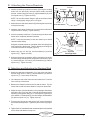
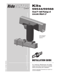
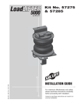
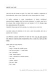
MN-643
(02511)
ECR 5461
Kit No. 39205
Please read these instructions completely before proceeding with installation
Parts List
Item
A
B
C
D
E
F
G
H
I
J
K
L
M
N
O
P
Q
R
S
T
Y
Z
AA
P/N
26391
26414
26380
07138
07137
58201
17247
18485
18460
17268
18495
13228
10308
18509
18508
18451
18484
18429
21745
18480
17219
13034
20086sub
Description
Quantity
Driver-Side Beam Assembly
1
Passenger-Side Beam Assembly
1
Panhard Rod Assembly
1
Upper Bracket (Right)
1
Upper Bracket (Left)
1
Bellows
2
1/2” - 13 x 1.75” Bolt GD8
14
1/2” Flat Washer
28
1/2” - 13 Nylock Nut
16
10mm Bolt GD8.8
8
10mm Nylock Nut
4
Spacer
2
U-Bolt
2
Washer .65ID x 1.25OD
4
5/8” - 18 Nut
4
3/4” - 16 Jam Nut
2
1/2” - 20 Hex Nut GD8
4
1/2” - Lock Washer
6
1/4” MNPT x 1/4” Tube Straight
2
9/16” Nylock Nut
1
9/16” - 12 x 5 Bolt GD8
1
Spacer
2
Air Line Assembly
1
Item
BB
CC
DD
EE
FF
GG
HH
II
JJ
KK
LL
MM
NN
OO
PP
QQ
RR
SS
TT
UU
VV
WW
P/N
10466
21230
18405
21234
18411
21233
17269
18518
18470
18435
10195
17271
17307
18509
18536
17305
18535
18534
10513
17286
10642
10445
Description
Quantity
8” Zip Tie
6
Poly Cap
2
5
/16" Flat Washer
2
Rubber Washer
2
5
/16" Star Washer
2
5
/16" Hex Nut
4
3/4” - 16 x 4” Bolt GD8
1
3/4” Flat Washer GD8
2
3/4” - 16 Nylock Nut GD8
1
3/8"-16 Nylock Nut
2
Flat Washer, 2.5" OD x .53 ID x .19 4
1/2"-13 X 3, Hex Cap Screw
2
5/8” - 18 x 6.5 Bolt
4
1.25” OD Flat Washer
8
5/8” Nyloc Nut
4
22mm Bolt
1
22mm Flat Washer
2
22mm Nyloc Nut
1
Axle Bracket
1
Centering Pin
1
Spring Retainer
1
Limiting Strap
1
Read all maintenance guidelines on page 7 before operating the vehicle.
Technical Support
1-800-248-0892
Ext. 2
1
DANGER: Compressed air can cause injury and damage to the vehicle and parts if it is not handled properly. For your
safety, do not try to inflate the air springs until they have been properly secured to the vehicle.
I. Getting Started
Remove Frame
Contact Overload
Upper Bracket
1. Elevate the rear of the vehicle and secure the frame with jack
stands.
Remove Bolts
2. Remove both of the leaf springs.
NOTE: Retain the front nuts and bolts to be reused.
Remove Gas
Tank Cover
Rivet
Driver-Side Only
3. Remove the rear contact overload frame brackets from both sides
of the frame rail.
4. Remove the bottom gas tank cover from the vehicle.
Figure 1
5. Remove the two bolts above the rivet on the driver-side of the
frame rail (Figure 1).
Passenger-Side
II. Attaching the Axle Beams
Nut
1. Attach the spring retainer (VV) to the passenger side beam using
the centering pin (UU). Tighten securely (Figure 2a).
Spring Retainer
Stock Bolt
Axle
Centering Pin
3. Attach the passenger side beam assembly to the axle with Ubolts (M), flat washers (N), and nuts (O) (Figure 2a). Torque to
128 ft/lbs.
Figure 2a
22 mm flat washer and
22 mm nyloc nut (behind beam)
22 mm bolt
Driver-Side Beam
22 mm flat washer
5/8" flat washer
5/8" bolt
Axle
5/8" nyloc nut
Figure 2b
4. For the driver-side, set the axle bracket (TT) onto the top of the
axle. Insert the bolts (NN) through the flat washers (OO), the
axle bracket, and the stock spring retainer. Fasten using flat
washers (OO) and nyloc nuts (PP) (Figure 2b).
5. Tighten and evenly torque to 128 ft/lbs.
5/8" flat washer
stock retainer
2. Install the passenger-side beam assembly (A) to the front spring
eye hanger using the supplied 16mm bolt (KK), flat washers
(LL), and nyloc nut (MM). Leave loose at this time.
Axle Bracket
6. Set the beam assembly onto the axle bracket. Insert the bolt
(QQ) through one flat washer (RR) and through the front of the
beam assembly. Fasten using a flat washer (RR) and a nyloc
nut (SS) (Figure 2b). Leave loose at this time.
NOTE: Index the alignment pin into the spring perch hole before
applying torque.
Technical Support
1-800-248-0892
2
Ext. 2
III. Attaching the Frame Brackets
1/2" Bolts
1. Install the passenger-side frame bracket (D) using the existing
holes from the previously removed frame contact overload
bracket. Attach using four bolts (G), eight flatwashers (H), and
four nylock nuts (I). Tighten securely.
Drill
1/2" Hole
10mm Bolts
NOTE: Be sure the bracket flange is tight to the bottom frame
flange. Clamp tightly using a pair of vice grips.
2. Attach the driver-side frame bracket (E) following the instructions
in the previous step.
3. Install two 10mm bolts (J) above the rivet on the driver-side frame
rail (See section I step 5). Tighten securely.
4. It will be necessary to drill two 1/2” holes through the driver-side
frame rail to completely attach this bracket.
Drill
1/2" Hole
Driver-Side Shown
Figure 3
Flat Washer
Flat Washer
Jam Nut
Bolt
Bolt
NOTE: It may be necessary to raise the chassis up to obtain
clearance when drilling.
Using the mounted bracket as a template, drill a hole through the
front-most hole in the bracket. There is already an exisiting slot
in the frame that will be enlarged (Figure 3).
5. Attach using one 1/2” bolt (G), two flat washers (H), and one
nylock nut (I). Tighten securely.
Spacer
Top View
Passenger-Side
Figure 4
6. Using the bracket as a template, drill the remaining hole under
the frame flange in between the two panhard rod mounts (Figure
3). Attach using one 1/2” bolt (G), two flat washers (H), and one
nylock nut (I). Tighten securely.
IV. Attaching and Adjusting the Panhard Rod
1. Attach the panhard rod assembly (C) to the driver-side frame
bracket using one 9/16” bolt (Y), two flat washers (H), and one
nylock nut (T). Leave loose at this time.
2. Lift or drop the rear of the frame so that it measures 31” from the
floor to the top of the frame.
3. Measure the distance between the tire and the frame. Pry the
frame side-to-side so that the distance is equal on both sides.
4. Adjust the hyme joint and attach it to the passenger-side beam
assembly using a 3/4” bolt (HH). Place the bolt through one flat
washer (II), through the flange, a 1/2” wide spacer (Z), the hyme
joint, another 1/2” wide spacer (Z), the other flange, one flat washer
(II) and one nylock nut (JJ). Tighten securely.
5. Turn the hyme joint so as to stay on the “ball” section throughout
the travel of the suspension. Tighten the jam nut securely (Figure
4).
6. Tighten the 9/16” panhard bolt and nut that was previously installed
on the driver-side bracket in step one.
Technical Support
1-800-248-0892
Ext. 2
3
V. Installing the Rolling Lobe Air Sleeves
Driver-Side Shown
1. Install the fitting (S) into the large, top stud of the rolling lobe air
sleeve. Tighten the fitting finger-tight plus 11/2 turns being careful
to tighten on the metal hex nut only.
NOTE: It may be necessary to raise the chassis to provide
adequate space to install the air sleeves.
2. Insert the studs of both rolling lobe air sleeves into the bottom
mounting hole of the beam assemblies on both sides of the vehicle.
Attach finger-tight using a 1/2” lock washer (R) and nut (Q).
3. Lower the frame down while guiding both studs on top of the
rolling lobe air sleeves through the holes in the upper mounting
bracket.
Figure 5
4. Attach the air sleeves using a 3/4” jam nut (P) on the large stud.
Use a lock washer (R) and 1/2” nut (Q) on the smaller stud.
Tighten the top mounts securely (Figure 5). Leave the bottom
loose at this time.
Gas Tank
Mount
Spacer
5. At this time, lightly oil and torque the axle bracket center
bolt to 321 ft. lbs.
Bolt
Bolt
Gas Tank
Cover
VI. Gas Tank Cover
Figure 6
1. Install the cover back in place by using two 10mm bolts (J) under
the frame on each side.
2. Insert the two spacers (L) in the back between the gas tank
mount and the gas tank cover. Attach with two 10mm bolts (J).
Tighten all bolts securely (Figure 6).
3. Install four 10mm nuts (K) onto the the previously installed bolts
on the inside of the frame rail. Tighten securely.
Technical Support
1-800-248-0892
4
Ext. 2
VII. Installing the Air Lines
Vehicle body
or bumper
1. Choose a convenient location for mounting the inflation valves.
Popular locations for the inflation valve are: the wheel well
flanges, the license plate recess in bumper, under the gas cap
access door, or through license plate itself.
DD
NOTE: What ever the chosen location is, make sure there is
enough clearance around the inflation valves for an air chuck.
Air Line to
Bellows
GG
FF
CC
2. Drill a 5/16 " hole to install the inflation valves.
EE
GG
3. Cut the air line assembly (AA) in two equal lengths.
CAUTION: When cutting or trimming the air line, use a hose
cutter (Air Lift P/N 10530), a razor blade or a sharp knife. A
clean, square cut will ensure against leaks. Do not use wire
cutters or scissors to cut the air line. These tools may flatten or
crimp the air line, causing it to leak around the O-ring seal inside
the elbow fitting.
Figure 7
4. Place a 5/16 " nut (GG) and a star washer (FF) on the air valve. Leave enough of the inflation valve in front of the nut
to extend through the hole and have room for the rubber washer (EE), flat washer (DD), and 5/16 " nut (GG) and cap
(CC). There should be enough valve exposed after installation - approximately 1/2 " - to easily apply a pressure gauge
or an air chuck (Figure 7).
5. Push the inflation valve through the hole and use the rubber washer (EE), flat washer (DD), and another 5/16 " nut
(GG) to secure it in place. Tighten the nuts to secure the assembly in place (Figure 7).
6. Route the air line along the frame to the air fitting on the air spring. Keep at least 6" of clearance between the air line
and heat sources, such as the exhaust pipes, muffler, or catalytic converter. Avoid sharp bends and edges. Use the
plastic tie straps (BB) to secure the air line to fixed, non-moving points along the chassis. Be sure that the tie straps
are tight, but do not pinch the air line. Leave at least 2" of slack to allow for any movement that might pull on the air
line.
7. Cut off air line leaving approximately 12" of extra air line. A clean square cut will ensure against leaks. Insert the air
line into the air fitting. This is a push to connect fitting. Simply push the air line into the straight fitting until it bottoms
out (9/16" of air line should be in the fitting).
VIII. Final Adjustments
1. Inflate both rolling lobe air sleeves to 25 p.s.i and check for leaks (refer to section IX).
2. Tighten both bottom rolling lobe mounts securely at this time.
3. The vehicle was set up for a rear top of frame height of 31”. Do not deviate from this height.
4.With the rear top of the frame at 31”, torque both 16mm pivot bolts on the front of the beam to 110 ft/lbs.
5. IMPORTANT: Check and re-torque all mounting hardware, especially the beam U-bolts, after 100 and 3,000
miles.
Technical Support
1-800-248-0892
Ext. 2
5
IX. Checking for Leaks
1. Inflate the air spring to 25 p.s.i.
2. Spray all connections and the inflation valves with a solution of 1/5 liquid dish soap and 4/5 water to check for leaks.
You should be able to spot leaks easily by looking for bubbles in the soapy water.
3. After the test, deflate the springs to the minimum pressure required to restore the Normal Ride Height, but not less
than 10 p.s.i.
4. IMPORTANT: Check the air pressure again after 24 hours. A 2 to 4 p.s.i. loss after initial installation is normal.
Retest for leaks if the loss is more than 5 lbs.
X. Fixing Leaks
1. If there is a problem with the swivel fitting, then:
a. Check the air line connection by deflating the spring and removing the line by pulling the collar against the fitting
and pulling firmly on the air line. Trim 1" off the end of the air line. Be sure the cut is clean and square. Reinsert
the air line into the push-to-connect fitting.
b. Check the threaded connection by tightening the swivel fitting another 1/2 turn. If it still leaks, deflate the air
spring, remove the fitting, and re-coat the threads with thread sealant. Reinstall by hand tightening as much as
possible, then use a wrench for an additional two turns.
2. If there is a problem with the inflation valve, then:
a. Check the valve core by tightening it with a valve core tool.
b. Check the air line connection by removing the air line from the barbed type fitting. CAUTION: Do not cut it off.
As this will usually nick the barb and render the fitting useless. Cut air line off a few inches in front of the fitting
and use a pair of pliers or vise-grips to pull/twist the air line off the fitting.
3. If the preceding steps have not resolved the problem, call Air Lift Technical Service at 1-800-248-0892 for assistance.
XI. Troubleshooting Guide
Problems maintaining air pressure, without on-board compressor.
1. Leak test the air line connections and threaded connection of the elbow into the air spring. See Section X to repair.
2. Leak test the inflation valve for leaks at the air line connection or dirt or debris in the valve core. See Section X to
repair.
3. Inspect air lines to be sure it is not pinched. Tie straps may be too tight. Loosen or replace strap. Replace leaking
components.
4. Inspect air line for holes and cracks. Replace as needed.
5. A kink or fold in the air line. Reroute as needed.
You have now tested for all of the most probable leak conditions that can be easily fixed. At this point the problem is
most likely a failed air spring - either a factory defect or an operating problem. Please call Air Lift at 1-800-248-0892 for
assistance or a replacement air spring.
Technical Support
1-800-248-0892
6
Ext. 2
XII. Maintenance and Operations
Minimum Air Pressure
Maximum Air Pressure
10 p.s.i.
100 p.s.i.
Failure to maintain correct minimum pressure (or pressure proportional to load), bottoming
out, over-extension, or rubbing against another component will void the warranty.
By following these steps, vehicle owners will obtain the longest life and best results from their air
springs.
1. Check the air pressure weekly.
2. Always maintain Normal Ride Height. Never inflate beyond 100 p.s.i.
3. If you develop an air leak in the system, use a soapy water solution to check all air line connections and the inflation
valve core before deflating and removing the air spring (see page 6).
4. When increasing load, always adjust the air pressure to maintain the Normal Ride Height. Increase or decrease
pressure from the system as necessary to attain Normal Ride Height for optimal ride and handling. Remember that
loads carried behind the axle (including tongue loads) require more leveling force (pressure) than those carried
directly over the axle.
5. IMPORTANT: For your safety and to prevent possible damage to your vehicle, do not exceed maximum Gross
Vehicle Weight Rating (GVWR), as indicated by the vehicle manufacturer. Although your air springs are rated at a
maximum inflation pressure of 100 p.s.i. The air pressure actually needed is dependant on your load and GVWR,
which may be less than 100 p.s.i. Check your vehicle owners manual and do not exceed the maximum load listed
for your vehicle.
6. Always add air to springs in small quantities, checking the pressure frequently. Air springs require less air volume
than a tire and inflate quickly.
7. Should it become necessary to raise the vehicle by the frame, make sure the system is at minimum pressure (10
p.s.i.) to reduce the tension on the suspension/brake components. Use of on-board leveling systems do not require
deflation or disconnection.
8. IMPORTANT: Check and re-torque all mounting hardware, especially the beam U-bolts, after 100 and 3,000
miles.
Technical Support
1-800-248-0892
Ext. 2
7
Thank you for purchasing Air Lift Products
Mailing Address:
AIR LIFT COMPANY
P.O. Box 80167
Lansing, MI 48908-0167
Street Address:
AIR LIFT COMPANY
2727 Snow Rd.
Lansing, MI 48917
Local Phone: (517) 322-2144
Fax: (517) 322-0240
For Technical Assistance call 1-800-248-0892
Technical Support
“The Choice of the Professional Installer”1010
1-800-248-0892
8
Ext. 2
Printed in the USA


![[U2.04.04] Notice d`utilisation du contact](http://vs1.manualzilla.com/store/data/006386513_1-3ff795ef61ec5d23149d6d36bfda261a-150x150.png)