1
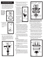
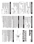
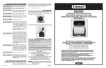
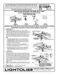
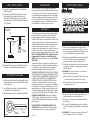
WALL SWITCH WIRING
MAINTENANCE
1. Unscrew the speed control cover and screw
base onto wall.
2. Connect the switch white wire to the black
(Hot) supply wire using a listed wire nut.
Connect the switch black wire to the black
(Hot) lead wire from the fan using a listed wire
nut. (Figure 7)
Periodic cleaning of your ceiling fan is the only
maintenance that is needed. When cleaning, use only
a soft brush or lint free cloth to avoid scratching the
finish. Abrasive cleaning agents are not required and
should be avoided to prevent damage to the finish.
Do not use water when cleaning your ceiling fan. It
could damage the motor or the blades and create
the possibility of an electrical shock or fire.
Models: 9848, 9856 & 9860
WARRANTY
White Supply
(Neutral)
Black lead
from fan
(Hot)
Black
Supply
(Hot)
Wall
Switch
Figure 7
3. Replace the front cover of the switch control
box with the supplied screws and tighten.
ATTACHING FAN BLADES
1. Insert one screw through the lockewasher and
into the motor hub. Do not tighten fully at this
time. (Figure 8)
2. Install the second screw in the same manner,
then tighten both screws fully.
3. Repeat steps 1 and 2 for the 2 remaining blades.
The ceiling fan you have purchased is warranted by
the manufacturer for one year from the date of
purchase against defects in workmanship and/or
materials. The motor is warranted for ten years. This
warranty means that only the parts that prove to be
defective during the period of warranty will be either
repaired or replaced at our option. The right is
reserved by the manufacturer to replace the whole
product in lieu thereof. Should repair become
necessary during the warranty period, write to: AIR
KING c/o LASKO PRODUCTS, INC., Appliance Service
Department, 820 Lincoln Ave., West Chester, PA
19380. Describe the problem you are having. DO NOT
SEND FAN!
This warranty does not apply if the damage occurs
because of accident, improper handling, installation
or operation, shipping damage, abuse, misuse or
unauthorized repairs made or attempted. ALL
WARRANTIES, EXPRESSED OR IMPLIED LAST FOR ONE
YEAR FROM DATE OF ORIGINAL PURCHASE, EXCEPT
FOR THE MOTOR. THIS WARRANTY DOES NOT COVER
LIABILITY FOR INCIDENTAL OR CONSEQUENTIAL
DAMAGES FOR ANY CAUSE WHATSOEVER. Some
states do not allow limitations on how long any
implied warranty lasts, or the exclusion or limitations
of incidental or consequential damages, so that the
above limitation or exclusion may not apply to you.
This warranty gives you specific legal rights, and you
may have other rights that vary from state to state.
FOR REPLACEMENT PARTS: Please call 1-800-9662028, Monday - Friday, between the hours of 8am
and 4 pm EST. Reference the type and style of product
when you call.
FOR QUESTIONS OR COMMENTS ABOUT YOUR
CEILING FAN: Please call 1-800-233-0268, Monday Friday, between the hours of 8am and 4pm EST.
Figure 8
INSTRUCTION MANUAL
Screw &
lockwasher
Blade
New 7/00
I N D U S T R I A L C E I L I N G FA N
READ AND SAVE THESE INSTRUCTIONS
1. Follow the recommended instructions for the
proper method of wiring your ceiling fan. If you
do not know enough about electrical wiring, have
your fan installed by a licensed electrician.
2. All wiring must satisfy National and Local electrical
codes. The ceiling fan must be grounded as a
precaution against possible electrical shock.
3. The electrical outlet box and joist must be securely
mounted and capable of reliably supporting at
least 50 pounds.
4. WARNING: To reduce the risk of fire, electrical
shock and/or personal injury:
a) Be sure electricity is turned off at the main fuse
box before wiring, cleaning or servicing.
b) Fan should not be mounted in areas where it
might become wet
RULES FOR SAFE OPERATION
1. Be careful of the fan and moving blades when
cleaning, painting or working near fan.
2. Do not put anything into the blades while they
are turning.
3. Do not bend the blade brackets when installing
the brackets, balancing the blades or cleaning the
fan.
4. WARNING: The fan must be hung with at least 7
feet of clearance from floor to blades.
INSTALLATION INSTRUCTIONS
4. Slide lower canopy down the pipe until it covers
the wiring. Tighten screw to hold in place.
1. Attach the hanger bracket to the electrical box
capable of reliably supporting at least 50 pounds.
Insert the screws through the slotted holes in the
bracket and attach to the electrical box. Tighten
both screws to the electrical box. (Figure 1)
5. Slide upper canopy on over the pipe and allow it
to temporarily rest on top of lower canopy.
NOTE: If bracket
and/or electrical box
are not securely
attached, the fan
could wobble.
Electrical Box
Mounting
Bracket
Screw
Figure 1
2. Insert electrical wire
into slotted hole in
pipe and run wires out
the other end of pipe.
(Figure 2)
Pipe
Wire
Slotted
Hole
Figure 2
3. Insert holding cup into pipe and place on motor
shaft. Line up holes and insert bolt through
washer, pipe, second washer, spring washer and
nut. Tighten nut and insert cotter pin into end
of bolt. Bend ends of cotter pin arms to lock into
place. (Figure 3)
Pipe
Spring
Washer
Bolt
Cotter
Pin
Nut
Plain
Washer
Plain
Washer
Cup
Shaft
Figure 3
6. Insert motor leads
Wires
through the hanger
ball and slide the ball
Pin
midway down the
pipe. Insert the spring Ground
wire &
pin through the top
Screw
holes of the pipe. Align
the grooves in the ball
with the pin and pull
up to fully seat the ball.
Screw
Tighten screw in side
of hanger ball. If
Pipe
Hanger
ground wire is not
Ball
attached, insert screw Figure 4
through ring at end of
green ground wire and tighten to top of hanger
ball. (Figure 4)
7. Hang the upper canopy on hook attached to
hanger bracket. Make sure the electrical box is
properly secured. If Romex cable (plastic sheathed)
was used to wire the electrical box, the presence
of a third wire connected to the electrical box
indicates that the box is grounded. This ground
wire may be a bare wire (no insulating jacket),
or a green insulated wire. The two supply wires
will be white and black insulated wires.
8. If the wiring to the electrical box is enclosed in
electrical conduit pipe, the ground wire may not
be present. The conduit itself could serve as the
ground.
GROUNDING:
9. Romex (plastic sheathed) Cable: If romex cable
was used to wire the electric box, connect the
green ground wire attached to the hanger ball
and the green ground wire in the Romex cable
using a 72B listed wire nut.
Supply Ground
Green or Bare
Black Supply
(Hot)
White Supply
(Neutral)
Green
Jumper Wire
Black Fan
(Hot)
White Fan
(Neutral)
Figure 5
NOTE: Check to see that all connections are tight,
including the ground and that no bare wire is visible
at the wire nuts, except for the ground wire.
11. Insert one of the phillips head screws in one of
the side holes of the mounting bracket, being
careful not to fully tighten. Leave a minimum of
1/8" distance between the screw head and
mounting bracket. Locate the hole opposite the
first screw and repeat this procedure. (Figure 6)
12. Raise the canopy up to the mounting bracket.
Apply light pressure upward on the canopy while
rotating it to the right. Rotate the canopy until
the two screws from step #11 drop into the side
hook slots in the canopy. Continue rotating until
the canopy is fully locked and stops rotating.
13. Insert the last two screws through the remaining
side holes of the canopy into the mounting
bracket. Tighten all four screws.
Mounting
Bracket
9a. Conduit Pipe: If the wiring to the electrical box
is enclosed in electrical conduit pipe, connect the
ground wire to the ground screw in the electrical
box.
Slot
10. Electrical Supply: Connect the fan motor white
wire to the supply white (Neutral) wire using a
listed wire nut. Connect the fan motor black wire
and the supply black (hot) wire using a listed wire
nut.
Canopy
Figure 6