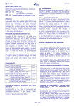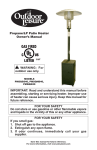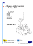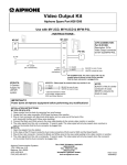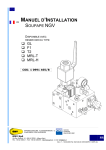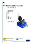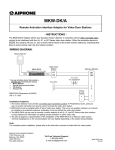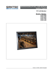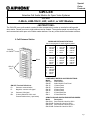
1
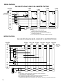
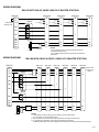
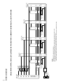
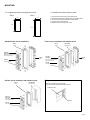
Special
Order
Products
GW-LE8
Selective Call Audio Module for Open Voice Systems
Use with:
C-ML/A, LEM-1DL/C, LEF, LAF-C, or LDF Masters
- INSTRUCTIONS The GW-LE8 is an audio module, used with other components to make up a selective calling audio
door station. Panels from two to eight stations can be created. The entrance panel can selectively call
and communicate with open voice inside master stations. Use any of the above listed master stations.
8 Call Entrance Station
*MODULAR ENTRANCE STATIONS
List of components for each entrance panel:
GW-LE8
w/ GW-DP
GW-3
GW-4P
(x2)
3 Call Panel
1
GW-LE8
1
GW-DP
1
GW-3P
1
GW-2
4 Call Panel
1
GW-LE8
1
GW-DP
1
GW-4P
1
GW-2
5 Call Panel
1
GW-LE8
1
GW-DP
1
GW-1P
1
GW-4P
1
GW-3
6 Call Panel
1
GW-LE8
1
GW-DP
1
GW-2P
1
GW-4P
1
GW-3
7 Call Panel
1
GW-LE8
1
GW-DP
1
GW-3P
1
GW-4P
1
GW-3
8 Call Panel
1
GW-LE8
1
GW-DP
2
GW-4P
1
GW-3
GW-LE8 Terminal Definitions:
D+
Common communication
DNegative, common call signal
Yel
Blu
2 Call Panel
1
GW-LE8
1
GW-DP
1
GW-2P
1
GW-2
Common Call signal
(8 wires) Selective Call-in and
communication wires (1 per button)
COMPONENT MODELS AND DESCRIPTIONS
Model
Description
GW-LE8
Audio Module
GW-DP
Audio Module Front Panel
GW-1P
1 Button Panel
GW-2P
2 Button Panel
GW-3P
3 Button Panel
GW-4P
4 Button Panel
GW-2
2 Panel Back Box
GW-3
3 Panel Back Box
SEMI-FLUSH AND SURFACE MOUNTING BOXES:
Model
Description
GW-002H Semi-flush Mt. Hood for GW-2
GW-002HB Surface Mt. Hood for GW-2
GW-003H Semi-flush Mt. Hood for GW-3
GW-003HB Surface Mt. Hood for GW-3
Pg. 1
WIRING DIAGRAM:
GW-LE8 WITH GW-4P, USING C-ML/A MASTER STATIONS
GW-LE8
Install jumper
between D+/D-
D+
DYel
C-ML/A
E
+
E
+
+
SKK-620
GW-4P
C-ML/A
1
Blu
+
SKK-620
E
+
1
Component
Module*
1
Component
Module*
4
Blu
Blu
Blu
Blu
Blu
SKK-620
E
+
1
3
Blu
+
+
C-ML/A
Component
Module*
2
Blu
SKK-620
C-ML/A
L
L
~
~
AC Power
Door Strike
1
L
L
L
L
Component
Module*
L
L
NOTES:
1. * Install bare wire end to "1" terminal
(DAK-2S contains two component modules).
2. Only components of the entrance panel that include wire
connections are shown here.
3. See C-ML/A instructions for complete installation information.
WIRING DIAGRAM:
GW-LE8 WITH GW-4P & GW-2P, USING LEF-3L MASTER STATIONS
GW-LE8
LEF-3L #1
LEF-3L #2
LEF-3L #3
LEF-3L #4
LEF-3L #5
LEF-3L #6
D+
DYel
E
+
R
1
E
+
R
E
+
R
E
+
R
E
+
R
E
+
R
+
GW-4P
1
Blu
PS-12C
2
Blu
1
3
Blu
1
4
Blu
1
GW-2P
1
Blu
2
Blu
Blu
Blu
Yel
~
~
AC Power
Door Strike
Pg. 2
1
1
RY-PA
Blk
Brn
Wht
Brn
Wht
Brn
Wht
Brn
Wht
Brn
Wht
Brn
Wht
NOTES:
1. In this example, the door station rings in on station #1 of each master station.
It can be wired to any unused station number.
2. Only components of the entrance panel that include wire connections are shown here.
3. For complete wiring information, please see the LEF-3L instructions.
If additional master stations are to be installed in each office/suite, wire them per the standard instructions.
Remove E/jumper on all
masters.
WIRING DIAGRAM:
GW-LE8 WITH GW-4P, USING LEM-1DL/C MASTER STATIONS
GW-LE8
Install jumper
between D+/D-
LEM-1DL/C
D+
DYel
GW-4P
PT-1210N
~
~
1
Blu
E
+
R
1
PT-1210N
~
~
2
Blu
LEM-1DL/C
LEM-1DL/C
E
+
R
PT-1210N
E
+
R
~
~
PT-1210N
E
+
R
~
~
1
3
Blu
LEM-1DL/C
1
4
Blu
Blu
Blu
Blu
Blu
1
~
~
EL
EL
EL
EL
NOTES:
1. Only components of the entrance panel that include wire
connections are shown here.
2. For complete wiring information, please see the LEM-1DL/C
instructions.
AC Power
Door Strike
WIRING DIAGRAM:
EL
EL
EL
EL
GW-LE8 WITH GW-4P & GW-2P, USING LEF-5 MASTER STATIONS
GW-LE8
LEF-5 #1
LEF-5 #2
LEF-5 #3
LEF-5 #4
LEF-5 #5
LEF-5 #6
D+
DYel
E
+
R
1
E
+
R
E
+
R
E
+
R
E
+
R
E
+
R
+
GW-4P
1
Blu
PS-12C
2
Blu
1
3
Blu
1
4
Blu
Remove D+/Djumper on all
masters.
1
GW-2P
1
Blu
1
2
Blu
Blu
Blu
Yel
~
~
AC Power
Door Strike
1
RY-PA
Blk
K1
L
K1
L
K1
L
K1
L
K1
L
K1
L
NOTES:
1. In this example, the door station rings in on station #1 of each master station.
It can be wired to any unused station number.
2. Only components of the entrance panel that include wire connections are shown here.
3. For complete wiring information, please see the standard LEF instructions.
If additional master stations are to be installed in each office/suite, wire them per the standard instructions.
Pg. 3
~
~
Yel
AC Power
Door Strike
D-
Blu
Blu
Blu
Blu
D+
Blu
Blu
Blu
Blu
Yel
GW-LE8
+
-
RY-PA
Blk
To Indv. Door
Strike &
Power
PS-12C
4
3
2
1
GW-4P
Yel
Blk
To Indv. Door
Strike &
Power
Yel
RY-PA
Blk
L
K1
E
+
R
K2
2
1
To Indv. Door
Strike &
Power
LEF-3L #2
Yel
RY-PA
-
E
1
LE-D
Blk
To Indv. Door
Strike &
Power
Yel
L
K1
E
E
+
R
K2
RY-PA
-
1
LE-D
2
1
LEF-3L #3
NOTES:
1. Remove D+/D- jumper on all masters.
2. Only components of the entrance panel that include wire connections are shown here.
3. For complete wiring information, please see the standard LEF instructions.
If additional master stations are to be installed in each office/suite, wire them per the standard instructions.
RY-PA
L
K1
E
+
R
K2
E
-
1
2
1
E
LE-D
LE-D
1
LEF-3L #1
Blk
GW-LE8 WITH GW-4P, USING LEF-3L MASTER STATIONS WITH COMMON AND INDIVIDUAL DOOR STATIONS
WIRING DIAGRAM:
Pg. 4
L
K1
E
+
R
K2
2
1
LEF-3L #4
MOUNTING:
1. Cut appropriate sized mounting hole into wall.
GW-2
2. Assemble and mount entrance panel
GW-3
4-1/2"
1. Open a hole in the back box to pass cable through.
2. Mount the GW-LE8 to the GW-DP using the supplied screws.
3. Mount the components to the GW-2 or GW-3 frame.
4. Mount the frame to the back box.
5. Replace the two mounting screw covers.
4-1/2"
8-1/8"
11-3/4"
Flush mount installation with weather hood:
Standard flush mount installation:
GW-3
GW-3
GW-003H
(Frame)
(Frame)
(Weather hood)
GW-DP +
GW-LE8
(GW-LE8 mounts to GW-DP
with supplied screws)
GW-3
(Box)
GW-4P
GW-DP +
GW-LE8
GW-3
(Box)
(GW-LE8 mounts to GW-DP
with supplied screws)
(Call switch panel)
GW-4P
(Call switch panel)
Surface mount installation with weather hood:
GW-3
GW-003HB
(Frame)
(Weather hood)
Filling in resident names:
1. Remove protective cover using opener.
(Opener included with GW-2 and GW-3 frames)
Protective Cover
GW-DP +
GW-LE8
(GW-LE8 mounts to GW-DP
with supplied screws)
Opener
GW-4P
(Call switch panel)
Pg. 5
OPERATION:
1. The entry station has multiple call buttons with an associated directory card. Press the button of the
person you wish to call.
2. The master station(s) will ring an electronic call tone as long as the call button on the entrance station
is being held. (A chime will be heard when using the C-ML/A room stations.)
3. With CM-L/A and LEM-1DL/C Master Stations: Press TALK button to answer the call.
With LEF Master Stations: Select the station button with the lit LED to answer. If the LED has gone out
(stays on for approx. 20 seconds), press the selector button assigned to the entry station.
4. At the inside station, press the TALK button to talk, and release to listen. The person at the entrance
station speaks hands free.
5. When finished with the call, press the OFF button on the master station.
6. NOTE: If the "Occupied" lamp is on, the system is in use. Wait until the LED goes out, or determine if
a master station has been left on unintentionally.
SPECIFICATIONS:
Power Source:
Impedance:
Communication:
Calling:
Wiring:
Door Release Wiring:
Wiring Distance:
Provided from master station.
C-ML/A: 1 SKK-620 or 4 "C" batteries per master.
LEM-1DL/C: 1 PT-1210N per master.
LEF: 1 PS-12C per system.
20 ohms
Hands free at entry station. Push-to-talk at master station.
C-ML/A: 4-Stroke chime
LEM-1DL/C: Momentary call tone
LEF: Momentary call tone and LED, remaining lit for approx. 20 seconds
C-ML/A: 2 conductors homerun per station to entrance panel.
LEM-1DL/C: 2 conductors homerun per station to entrance panel.
LEF: 4 common (E, R, +, -) plus 1 individual per sub, looped; or 5 conductors homerun
to each master. Shielded cable is recommended.
Use Aiphone #822202 (2 conductor) or 822212 (12 conductor) for max. 8 station wiring.
2 conductors looped through stations to strike and strike power supply.
C-ML/A: 245' with 22AWG; 590' with 18AWG.
LEF/LEM: 650' with 22AWG; 1,600' with 18AWG.
NOTE:
Only information concerning the GW-LE8 is shown here.
For complete wiring information, please see the appropriate system instructions.
Aiphone Communication Systems
1700 130th Ave. N.E.
Bellevue, WA 98005
(425) 455-0510
FAX (425) 455-0071
TOLL FREE TECHNICAL SUPPORT:
(800) 692-0200
TOLL FREE FAX LINE:
(800) 832-3765
E-MAIL: [email protected]
Pg. 6
GW-LE8 Instr.
1001bkjd