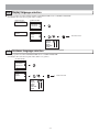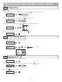
1
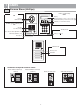
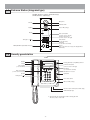
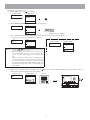
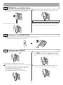
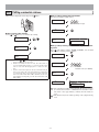
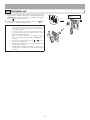
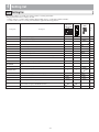
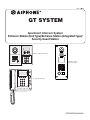
0311 A OI
GT SYSTEM
6(59,&(0$18$/
Apartment Intercom System
Entrance Station (Unit Type)/Entrance Station (Integrated Type)/
Security Guard Station
Entrance Station (Unit type)
3
E
F
D
A
B
C
2
M
P
7
W
9
S
U
V
8
T
Q R
O
G
N
I
6
K
L
5
H
J
4
Z
1
X Y
Entrance Station
(Integrated type)
0
O
N
9
Z
S
I
L
V
T
U
W
K
8
E
6
M
P
J
G
H
7
Q R
Security guard station
3
D
A
B
5
F
2
4
C
1
X Y
0
OPERATION MANUAL
PRECAUTIONS
General Prohibitions
Prohibition to Dismantle the Unit
Prohibition on Subjecting the Unit to Water
General Precautions
WARNING
(Negligence could result in death or serious injury.)
1. Do not dismantle or alter the unit. Fire or electric shock could result.
2. Do not connect non-specified power sources to the +, - terminals. Also, do not install
two power supplies in parallel to a single input. Fire, damage, or system malfunction
could result.
3. Keep the unit away from water or any other liquid. Fire or electric shock could result.
4. Do not put any metal or paper into the unit through the openings. Fire, electric shock,
or unit trouble could result.
5. High voltage is present internally. Do not open the case. Electric shock could result.
6. Do not use a power supply with a voltage other than the specified. Fire or electric shock
could result.
CAUTION
(Negligence could result in injury to people or damage to
property.)
1. Do not place (install) the unit in locations subject to frequent vibration or impact. Injury or damage could result if the unit falls.
2. Do not press on the LCD or subject it to high impact. The LCD glass could break which
could result in an injury.
3. If the LCD is punctured, do not allow skin contact with the liquid crystal inside. Inflammation could result.
* If liquid crystal is ingested, immediately gargle with water and seek medical attention.
* If contact with the eyes or skin occurs, clean with pure water for at least 15 minutes and
seek medical attention.
4. Do not install the unit in any of the following locations. Fire, electric shock, or unit
trouble could result.
* Places under direct sunlight or places near heating equipment that varies in temperature.
* Places subject to dust, oil, chemicals, etc.
* Places subject to moisture and humidity extremes, such as bathrooms, cellars, greenhouses, etc.
* Places where the temperature is quite low, such as inside a refrigerated area or in front
of an air conditioner.
* Places subject to steam or smoke (near heating or cooking surfaces).
* Where noise generating devices such as dimmer switches or inverter electrical appliances are close by.
5. Do not put anything on or cover the unit with cloth, etc. Fire or unit trouble could result.
6. For power supply, use Aiphone power supply model or model specified for use with
system. If non-specified product is used, fire or malfunction could result.
7. When performing call tests or checking the chime volume or call volume, make sure the
handset is placed on the main unit. Failure to do so may result in injury to the ears.
General Precautions
1.
2.
3.
4.
5.
6.
7.
8.
9.
10.
11.
12.
13.
14.
15.
16.
17.
18.
19.
-2-
The unit turns inoperative during power failure.
In areas where broadcasting station antennas are close by, intercom system may be affected by radio frequency interference.
Keep the unit more than 1 m away from radios or TV sets.
Be careful about where the unit is used, as use of computers, televisions, or radios near the
unit may affect transmission from the unit or cause unwanted noise.
When wall-mounted, the top of the unit may darken. This does not indicate a malfunction.
If the unit is down or does not operate properly, turn off the unit's power supply.
The unit case may become warm with use, but this is not a unit malfunction.
If the surface of an entrance station freezes during wintertime, the picture may become
difficult to see or the buttons may not move, but this is not a malfunction.
Security guard stations are for indoor use only. Do not use outdoors.
If a strong light shines on the main unit screen, the picture will turn white or only silhouettes will be visible. But this is not a unit malfunction.
As to other manufacturer's devices (such as sensor, detectors, door releases) used with this
system, comply with the Specifications and Warranty conditions that the manufacturers or
venders present.
If a cellular phone is used close by, the unit may malfunction.
The LCD panel is manufactured with very high precision techniques. Please be aware of
this in advance.
Talk within 50 cm (20") or less from the unit. If you stand too far away, it may be difficult
for the other person to hear the communication.
If there are loud noises around the unit (such as music playing or children crying), the
sound may break up and be difficult to hear.
During communication, if you speak before the other person has finished talking, your
voice may not come through clearly. Communication will proceed smoothly if you wait
until the other person has finished before speaking.
The outline of video images displayed by an entrance station may differ from that of the
actual person(s) or background, but this is not a malfunction.
When putting a hearing aid into T-mode and approaching the unit, the intercom system
may be affected by radio frequency interference etc., depending on the installation environment.
The sensor of an entrance station (integrated type) may activate due to moving shadows or
moving tree branches, etc. and cause a message to display, but this is not a malfunction.
-3-
1
NAMES
1-1
Entrance Station (Unit type)
Name scrolling module
GT-NS-V (VIGIK-compatible)
GT-NS
Camera module
GT-VA
Display
Back search button (or move the cursor to the left)
Forward search button (or move the cursor to the right)
Camera
Illuminator LED
Call button (or set and move forward)
Speech module
Cancel button (or set and return)
GT-DA-L (guidance-enabled type)
GT-DA
3
F
D
A
E
P
7
W
9
S
U
V
8
T
Q R
O
M
N
I
G
K
L
6
H
J
5
In Use LED (orange)
Door call-in indicator (GT-DA-L only)
Door release indicator (GT-DA-L only)
B
4
Ten key module
Z
2
C
1
Speaker
X Y
GT-10K
0
10 key (0 to 9,
Talk indicator (GT-DA-L only)
, #)
Microphone
Switch module
GT-SW
Directory card
Call button
Combination examples for entrance stations
Audio/video, 10 key type
I
S
L
P
T
I
L
F
E
6
P
W
S
J
G
T
U
M
K
8
0
-4-
3
5
N
O
A
B
D
H
7
C
2
4
9
Z
1
X Y
E
6
N
W
J
G
U
M
K
8
0
Q R
3
5
F
A
B
D
H
7
C
2
4
9
O
1
Q R
Z
Audio only, 10 key type
V
Audio/video, Direct Select type
(8 stations)
V
Audio only, Direct Select type
(8 stations)
X Y
1-2
Entrance Station (Integrated type)
GT-DMV (Guidance-enabled + VIGIK-linked type)
GT-DM (Guidance-enabled type)
Microphone
Camera
Illuminator LED
Speaker
In Use LED (orange)
Display
Back search button
(or move cursor to the left)
Forward search button
(or move cursor to the right)
10 key (0 to 9,
, #)
Cancel button
(or set and return)
Call button
(or set and move forward)
Sensor
(If the sensor detects an object, the display will be
illuminated.)
VIGIK (GT-DMV only/available in France)
Security guard station
GT-MK
Handset
Hearing aid T-mode compatibility symbol*1
Display
Forward search button
(or move cursor to the right)
Cancel button
(or set and return)
Call button
(or set and move forward)
P
7
W
9
U
V
8
T
Q R
0
Light button
O
M
N
L
6
K
I
5
H
, #)
J
4
G
10 key (0 to 9,
This button is not used.
F
E
D
3
B
A
2
Z
1
Speaker
C
Back search button
(or move cursor to the left)
S
1-3
X Y
Door release button
Off hook LED (orange)
Call tone volume switch (low, medium, high)
USB terminal (B type)
*1: This unit emits an electromagnetic field for hearing aids with
T-mode to produce clear audio.
-5-
2
OPERATIONS (ENTRANCE STATION)
2-1 Calling residential stations
Calling with the switch module
Press the call button for the residence that you want to call.
The door call-in indicator will light up and you will hear a call tone. Audio guidance will be heard depending on the settings.
Calling with the name scrolling module or GT-DMV/GT-DM.
Display the residential station to be called.
(1) Display using scrolling to search
1 In the standby mode, use the and buttons to display the room number and resident name.
Use the and buttons to search for the desired residential station.
• Depending on the settings, the resident name may only display.
• The display order may be according to room number or name.
WELCOME
WELCOME
2 Press the
button.
101
SMITH
NAME SCROLL
ROOM NO. 101
SMITH
:CALL
:CANCEL
(2) Display using room number to search
1 In the standby mode, enter the room number using [0] to [9] on the 10 key to display the room number and resident name.
• Depending on the settings, the resident name may only display.
WELCOME
WELCOME
1 0 1
Room number (1 to 6 digits)
2 Press the
101
SMITH
button.
NAME SCROLL
* If there is no relevant room number, the message below is displayed.
ROOM NO. 101
SMITH
NO ENTRY
:CALL
:CANCEL
<
NO ENTRY
>
* When the trunk of the residential station that has been called
is in use, the in use LED lights up to indicate that the
residential station cannot be used.
-6-
(3) Display by using letters to search
1 In the standby mode, press [ ] on the 10 key.
WELCOME
WELCOME
2 When "ENTER A LETTER" displays, use the 10 key to enter letters.
ENTER A LETTER
7
S
S
S
7
Q R
P
:CALL
7
Q R
P
Q R
P
P
7
S
ENTER A LETTER
Q R
...
S
:CANCEL
Resident name (ex. "SMITH")
3 The room number and name for the resident whose initial corresponds to the entered letter will display.
• Depending on the settings, the resident name may only display.
101
SMITH
ENTER A LETTER
:CALL
NOTES: 1.
2.
3.
* If there is no relevant resident name, the message below is displayed.
ROOM NO. 101
SMITH
S
NO ENTRY
:CANCEL
CALLING
SMITH
ENTER A LETTER
NO ENTRY
S
Pressing the
or
button for approximately 2 seconds will display the resident names in succession.
If both room number 111 and 1111 exist, the resident name for
room 111 will be displayed when 1, 1, 1 is entered, and the resident
name for room 1111 will be displayed if 1 is entered one more
time.
Stations can be made to display in order by room number using the
menu screen settings. (The order starts with the lowest digit from 0
to 9 and then the order goes by letter.) In cases where room numbers such as A101, A201, A901, A1001, and B101 exist, the order
starts with the lowest digit and goes in the order A101, A201, A901,
B101, A1001.
Call the residential station after it is displayed.
4 When the desired residential station is displayed, press the
Audio guidance will be heard depending on the settings.
:S
:CALL
:CANCEL
button. The door call-in indicator will light up and you will hear a call tone.
CALLING
ROOM NO. 101
SMITH
:CANCEL
-7-
5 When the other person answers, communication starts and the talk indicator lights up.
Audio guidance will be heard depending on the settings.
IN COMMUNICATION
IN COMMUNICATION
ROOM NO. 101
SMITH
:CANCEL
6 When the door is released, the door release indicator lights up.
Audio guidance will be heard depending on the settings.
DOOR OPEN
IN COMMUNICATION
ROOM NO. 101
SMITH
:CANCEL
2-2
Calling security guard stations
Select the security guard station and press the
button. You will hear a call tone. Audio guidance will be heard depending on the settings.
NAME SCROLL
ROOM NO. 001
SECURITY GUARD
2
A
G
B C
3
5
J
H I
D
4
K L
P
S
8
W
T
U V
E F
6
M
7
N O
9
:CALL
X Y
Z
1
Q R
0
2-3
1
:CANCEL
Door release
In the standby mode, enter the access code (4 to 6 digits) after entering [#] on the 10 key. Audio guidance will be heard depending on the settings.
WELCOME
7
S
O
I
M
N
P
6
K
J
5
H
G
4
L
WELCOME
Q R
Access code (ex. "4567")
2
The door is released.
DOOR OPEN
DOOR OPEN
* If the access code is incorrect, the message below is displayed.
DENIED
<
-8-
DENIED
>
3
3-1
1
OPERATIONS (SECURITY GUARD STATION)
Calling from an entrance station
When the call is from an entrance station, the call tone will ring for
approximately 10 seconds and the entrance station number will be
displayed.
3
When you are done talking, hang up the handset to end the call.
• Communication ends automatically after approximately 3 minutes.
1
T
8
B
C
S
L
3
E
9
V
N
X
2
1
5
T
8
I
B
S
K
U
C
L
3
E
9
V
N
X
1
O
Y
Z
0
3-2
F
6
W
R
M
P
J
G
2
D
H
A
4
7
O
Y
With the expanded system, the display number of the entrance station
varies depending on the common line connection of the entrance station and security guard station.
Connected to same common line: "Set number" is displayed as is
Ex.) Call from entrance station #1: "MAIN ENTRANCE: 01" is
displayed
Connected to separate common line: "Set number + 8"
Ex.) Call from entrance station #1: 1 + 8 = 9, so "MAIN ENTRANCE: 09" is displayed
Lift the handset to respond.
Q
F
6
W
K
U
0
Z
5
I
R
M
P
2
J
G
H
D
7
A
4
Q
Door release
Press the door release button while in communication with the entrance station.
2
Door release is activated at the entrance station.
Depending on the electric door release system that you use, door release may be active only while the door release button is pressed.
1
5
T
8
I
B
S
K
U
C
L
3
E
9
V
N
X
O
Y
Z
0
3-3
F
6
W
R
M
P
J
G
2
D
H
A
4
7
Q
Light control
Turning the entrance light on (when light is installed in common area)
Press the light button once during calling or communication from the
entrance station.
J
5
T
8
I
B
S
K
U
C
L
3
E
9
V
N
X
0
F
6
W
R
M
P
2
D
G
A
H
The outside light at the entrance will only turn on for the preset duration of time.
This function is not available if a surveillance camera is installed in the
common area.
1
4
7
Q
O
Y
Z
1
2
-9-
3-4
1
Calling from a residential station
When a call is received from a residential station, a call tone will sound for approximately 10 seconds and the room number and resident name will be displayed.
3
When you are done talking, hang up the handset to end the call.
1
2
5
T
8
B
C
D
H
J
I
S
K
L
U
3
E
F
6
W
R
M
P
7
A
G
4
Q
9
V
N
O
Y
Z
X
0
NOTES: If a call is not responded to, a record is kept.
2
The communication will be ended automatically after approximately 1
minute when hands-free communication is used at the residential station or after approximately 3 minutes when the handset is used.
Lift the handset to respond.
1
5
T
8
B
C
D
I
S
L
3
E
9
V
N
X
0
3-5
1
F
6
W
K
U
M
R
O
Y
Z
2
J
P
H
A
G
4
7
Q
Calling from the doorbell button
When the doorbell button is pressed, a call tone will sound while the button is being pressed.
• A different call tone sounds. (Communication is not possible.)
1
2
A
3
B C
D
E F
4
G
5
H I
J
6
K L
M
N O
7S
PQ
8
R
T
9Z
WX
U V
Y
0
3-6
1
Calling entrance stations
3
Lift the handset and press the 10 key [ ] button.
Press the button to communicate with the entrance station. If there
is no corresponding entrance station, "DENIED" will be displayed.
• While in communication, you can use the light button and door release button.
1
T
8
B
C
S
L
3
E
F
6
W
K
U
9
V
N
X
0
O
Y
Z
5
I
R
M
P
J
G
2
D
H
A
4
7
Q
1
T
8
B
C
S
L
3
E
9
V
N
X
O
Y
Use the 10 key to select the desired entrance station.
With the expanded system, the display number of the entrance station varies depending
on the common line connection of the entrance station and security guard station.
Connected to same common line: "Set number" is displayed as is
Ex.) Calling entrance station #1: Enter [1]
Connected to separate common line: "Set number + 8"
Ex.) Calling entrance station #1: 1 + 8 = 9, so enter [9]
4
When you are done talking, hang up the handset to end the call.
• Communication ends automatically after approximately 3 minutes.
1
T
8
B
C
S
L
3
E
9
V
N
X
1
T
8
B
C
L
3
E
F
6
W
K
U
9
V
N
X
0
O
Y
Z
5
I
R
M
P
2
J
G
H
D
7
A
4
Q
- 10 -
F
6
W
K
U
0
O
Y
Z
5
I
R
M
P
2
J
G
H
D
7
A
4
Q
S
2
F
6
W
K
U
0
Z
5
I
R
M
P
2
J
G
H
D
7
A
4
Q
3-7
Calling residential stations
Lift the handset, display the name and press the
button.
Making a call by entering the room number
Enter the room number with the 10 key.
AIPHONE
1
S
K
C
T
3
6
9
L
E
8
U
V
X
0
F
N
O
Y
Z
B
W
5
M
P
J
G
2
I
R
D
A
H
0
Room number (1 to 6 digits)
1
4
7
Q
1
101
SMITH
Making a call by name scrolling
Use the and buttons to search names by scrolling.
AIPHONE
AIPHONE
7
S
S
7
Q R
P
7
Q R
P
7
Q R
S
ENTER A LETTER
P
3.
Pressing the
or
button for approximately 2 seconds will display the resident names in succession.
If both room number 111 and 1111 exist, the resident name for
room 111 will be displayed when 1, 1, 1 is entered, and the resident
name for room 1111 will be displayed if 1 is entered one more
time.
Stations can be made to display in order by room number using the
menu screen settings. (The order starts with the lowest digit from 0
to 9 and then the order goes by letter.) In cases where room numbers such as A101, A201, A901, A1001, and B101 exist, the order
starts with the lowest digit and goes in the order A101, A201, A901,
B101, A1001.
P
2.
NO ENTRY
Making a call by entering a letter and selecting a corresponding name
Press [ ] on the 10 key to display "ENTER A LETTER", enter an initial
with the 10 key and then press the button.
101
SMITH
NOTES: 1.
If the room number does not exist
S
101
SMITH
101
SMITH
Q R
...
S
Resident name (ex. "SMITH")
101
SMITH
101
SMITH
When there is no name starting with A
NO ENTRY
:A
1. The communication will be ended automatically after approximately 1 minute when hands-free communication is used at the residential station or after approximately 3 minutes when the handset is
used.
2. This function may not be usable depending on the equipment being
used.
- 11 -
Calling another security guard station
Lift the handset, display the security guard station and press the
1
1
2
AIPHONE
E F
5
6
K L
N O
7S
8
R
9Z
WX
U V
0
7
Q R
P
7
Q R
P
P
P
7
Q R
7 ...
S
ENTER A LETTER
Making a call by security guard station name scrolling
Use the and buttons to search security guard station names by scrolling.
S
Y
Z
W
Y
9
X
0
4
H I
F
O
T
V
E
N
S
6
PQ
S
B C
3
L
M
U
C
J
K
D
B
G
T
8
Making a call by entering letters and selecting the corresponding security guard station
Press [ ] on the 10 key to display "ENTER A LETTER", enter a security
guard station name with the 10 key and then press the button.
3
A
5
M
P
J
G
2
I
R
D
H
A
4
7
Q
button.
S
3-8
Q R
S
Security guard station name
(Ex.: [SECURITY GUARD A])
AIPHONE
001
SECURITY GUARD A
001
SECURITY GUARD A
001
SECURITY GUARD A
When there is no security guard
station name starting with S
NO ENTRY
:S
001
SECURITY GUARD A
Making a call by entering the security guard station number
Enter the security guard station number with the 10 key.
AIPHONE
0
0
NOTES: 1.
Pressing the
or
button for approximately 2 seconds will display the resident names in succession.
If both room number 111 and 1111 exist, the resident name for
room 111 will be displayed when 1, 1, 1 is entered, and the resident
name for room 1111 will be displayed if 1 is entered one more
time.
2.
1
Room number (1 to 6 digits)
Making a call using the ID
After pressing [ ] and [1] on the 10 key, enter [0] plus the security guard
station ID number (1 to 4), and then press the button.
001
SECURITY GUARD A
• You will hear a low-volume call tone from the handset.
1
1
I
2
B
C
E
S
N
F
O
0
1
4
H
1
2
3
B C
E F
4
5
H I
6
K L
M
N O
7S
8
PQ
Y
J
X
G
6
L
V
D
T
U
R
T
0
A
J
K
8
G
3
9
5
R
Z
H
W
P
7
M
G
4
Q
D
U V
9Z
WX
NO ENTRY
I
If the room number does not exist
A
001
SECURITY GUARD A
Y
0
With the expanded system, the security guard station number varies
depending on the common line connection of the security guard station.
Connected to same common line: "Set number" is displayed as is
Ex.) Calling security guard station #1: Enter [1]
Connected to separate common line: "Set number 2"
Ex.) Calling security guard station #1: 1 + 2 = 3, so enter [3]
NOTES: If the security guard station does not exist, "DENIED" will be displayed.
- 12 -
3-9
1
Missed call
If a security guard station fails to respond to a call from a residential
station, "MISSED CALLS" is displayed on the display. Press the
button to display the room number and name of the residential station
that made the call.
MISSED CALLS
1
2
3
When the room number and name is displayed, press the button to
erase the displayed record. Other records will not be deleted.
101
SMITH
NOTES: 1.
2.
The security guard station can hold up to 20 missed calls.
A record of answered calls is not kept.
A
3
B C
D
E F
4
G
5
H I
J
6
K L
M
N O
7S
PQ
8
R
T
9Z
WX
U V
Y
0
2
When the room number and name is displayed, lift the handset and
press the button to call the residential station that is displayed.
101
SMITH
3-10 Call transfer/Communication transfer
In the standby mode, press [ ], [1] and [ ] to display "RECEPTION
MODE". In this mode, you can transfer all calls from an entrance to the
security guard station.
Press [ ], [1] and [ ] again to cancel the setting.
4
G
P
3
W
U V
E F
6
8
T
N O
9
X Y
E01 101
SMITH
1
2
3
A
B C
D
E F
4
5
G
After the residential station answers, hang up the handset to establish
communication between the entrance station and the residential station.
When there is no one at the residential station, hang up the handset
and pick it up again to communicate with the entrance.
K L
M
4
J
Lift the handset to communicate with the entrance station.
B C
5
7
0
In "RECEPTION MODE", all of the calls from entrance stations to
residential stations are transferred to security guard stations. The call
tone sounds, and then the called room number and name flash on the
screen along with the entrance station number.
2
3
H I
D
1
2
A
3.
1
Q R
S
2.
If there are multiple security guard stations, you can make and cancel the transfer setting on any security guard station to switch the
setting for the system overall.
Calls from an entrance station are transferred to all security guard
stations that are linked to the corresponding residential station. The
call tone sounds on all security guard stations at the same time.
A call to a residential station that is not linked to a security guard
station will result in a call to the residential station directly.
Z
NOTES: 1.
H I
J
6
K L
M
N O
7S
PQ
8
R
T
9Z
WX
When transferring a call to the called residential station, press the
button.
U V
Y
0
- 13 -
3-11 Emergency call
1
When an emergency alarm switch is locked (or when a wire disconnection occurs), an alarm sounds at the security guard station and
"EMERGENCY" and the room number are displayed alternately.
Press the button to stop the alarm.
2
Lift the handset, check the name on the display and press the
to communicate with the residential station.
2
5
T
8
I
B
K
U
C
L
3
E
9
V
N
X
0
- 14 -
F
6
W
R
M
P
H
J
6.
G
5.
7
D
4.
1
4
Q
A
3.
If an emergency call is already active on a security guard station
and that station is in communication, another security guard station
cannot interrupt. (An in-use tone will be heard from the handset of
the security guard station.)
The emergency alarm is given priority even when the system is in
use. (Alarms can be activated at the same time for up to 5 units.
This excludes GT-2C-L and GT-2C.)
When a security guard station has received multiple emergency
alarms, an arrow will be shown to the right of "EMERGENCY" on
the display.
and
buttons to
When the arrow is displayed, you can use the
select another residential station.
Emergency calls while the system is in use can be made after other
communication is terminated.
With the GT-2C-L and GT-2C, it is possible to transfer to a security guard station even when there is a security alarm, depending on
the settings.
S
2.
button
O
Y
Z
NOTES: 1.
EMERGENCY
SMITH
4
Setting list
4-1 Setting list
The following settings are possible at an entrance station or security guard station.
• The program menu varies according to the unit.
× = These items are set when a unit is installed. When making changes, consult with an qualified installer.
= These items can be set according to the installation equipment and unit application.
GT-DMV/GT-DM
GT-NS-V/GT-NS,
GT-DA-L/GT-DA,
GT-VA
Description
I
L
P
S
E
6
N
W
J
G
T
U
M
K
8
F
3
5
9
O
A
B
D
H
7
C
2
4
Page
no.
Z
1
Q R
V
Setting item
GT-MK
X Y
0
SELECT LANGUAGE Select the display language.
17, 22
GUIDE LANGUAGE
Select the guidance language.
CHANGE ID CODE
Change the ID code.
ACCESS CODE
Set the access code for door release at the entrance station.
18
RESIDENT INFO.
Enter and change resident data (names and room numbers).
19, 23
SET TIMER
Set various timers.
17
18, 22
CHANGE GREETING Change the greeting message.
20
PROGRAMMING
Perform link settings.
TRANSFER DATA
Transfer link information to another entrance station or security guard station.
VERIFY PROGRAM
Perform a link check.
SCROLL SPEED
Set the scroll speed for display messages and resident names, etc.
MONITOR
ENTRANCE
Select the setting for monitoring with the entrance station camera from a residential
station.
CALL-IN DISPLAY
Select the screen switching for residential stations when a call is received.
LIGHT OR CCTV
Select the operation performed when the light button on a residential station is
pressed.
DISPLAY ROOM NO.
Select room number display for the screen display.
STANDBY SCREEN
Select the standby screen.
20
BRIGHTNESS
Adjust the screen brightness.
21
SORT SETTING
Select the display order during searching.
OPTIONAL OUTPUT
Perform settings for outputting signals to security guard stations and for outputting
signals from the emergency alarm RY-RY terminal.
QUIT
Quit the program mode.
21, 23
16, 22
- 15 -
5
CHANGING SETTINGS (ENTRANCE STATION)
5-1 Setting method
When changing settings, use the GT-NS-V/GT-NS or GT-DMV/GT-DM program mode.
Program Mode
1
In the standby mode, enter the 4-digit ID code after entering [#] and [ ] on the 10 key. (Initial setting: 1111)
WELCOME
WELCOME
1
1
1
1
ID code
2
The "RE-ENTER ID CODE" is displayed. Re-enter [ ] and the 4-digit ID code.
RE-ENTER ID CODE
ENTER ID CODE
RE-ENTER ID CODE
_
1
The first menu item is displayed. Use the
SELECT LANGUAGE
1
and
buttons to select the desired menu item.
MENU
SELECT LANGUAGE
GUIDE LANGUAGE
CHANGE ID CODE
Previous Next
item
item
:ENTER
4
When quitting the program mode, select "QUIT" and press the
QUIT
1
ID code
:CANCEL
3
1
button.
MENU
QUIT
:QUIT
- 16 -
5-2 Display language selection
Start the program mode with the GT-NS-V/GT-NS or GT-DMV/GT-DM and select "SELECT LANGUAGE".
Select English, French, German, Spanish, Dutch, or Italian.
SELECT LANGUAGE
MENU
SELECT LANGUAGE
GUIDE LANGUAGE
CHANGE ID CODE
:ENTER
SELECT LANGUAGE
ENGLISH
SELECT LANGUAGE
ENGLISH
FRANÇAIS
DEUTSCH
:ENTER
Next menu item
ENGLISH
FRANÇAIS
DEUTSCH
ESPAÑOL
NEDERLANDS
ITALIANO
5-3 Guidance language selection
Start the program mode with the GT-DMV/GT-DM and select "GUIDE LANGUAGE".
Select English, French, German, Spanish, Dutch, Italian or no guidance.
MENU
SELECT LANGUAGE
GUIDE LANGUAGE
CHANGE ID CODE
:ENTER
GUIDE LANGUAGE
NO GUIDANCE
ENGLISH
FRANÇAIS
:ENTER
Next menu item
NO GUIDANCE
ENGLISH
FRANÇAIS
DEUTSCH
ESPAÑOL
NEDERLANDS
ITALIANO
- 17 -
5-4 Changing the ID code
1
Start the program mode and select "CHANGE ID CODE".
CHANGE ID CODE
MENU
SELECT LANGUAGE
GUIDE LANGUAGE
CHANGE ID CODE
:ENTER
The current ID code is displayed. Enter the new 4-digit ID code after entering [ ] on the 10 key.
Current ID code
CHANGE ID CODE
ENTER ID CODE
1111
0
1
3
B
E
New ID code (Ex.: "0123")
:ENTER
3
Press the
D
2
A
+ 4 DIGITS
F
CHANGE ID CODE
1111
C
2
button to return to the menu.
CHANGE ID CODE
0123
ID code after change
CHANGE ID CODE
ENTER ID CODE
0123
+ 4 DIGITS
:ENTER
5-5 Access code setting
1
Start the program mode and select "ACCESS CODE".
ACCESS CODE
MENU
ACCESS CODE
RESIDENT INFO.
SET TIMER
:ENTER
The current digit is displayed after "NO. OF DIGIT". Set a digit from 4 to 6.
Enter the digit using the 10 key or, with the GT-DMV/GT-DM, select it by using the
NO. OF DIGIT
4
6
H
N
:NEXT
M
INPUT 4-6
W
0
buttons, and then press the
button.
:NEXT
9
X Y
INPUT 001-500
:QUIT
Enter the access code, and the press the button.
* Codes with more digits than the set number of digits for access codes cannot be entered.
ACCESS CODE : 001
111111
Current access code
ACCESS CODE
ACCESS CODE 001
11111_
:NEXT
5
and
ACCESS CODE
ACCESS CODE 001
4
button.
:ENTER
"ACCESS CODE: 001" will be displayed.
Up to 500 access codes can be set. Select access codes from "001" to "500".
Enter the digit using the 10 key or, with the GT-DMV/GT-DM, select it by using the
ACCESS CODE : 001
buttons, and then press the
Z
3
4
G
Current digit
and
ACCESS CODE
O
ACCESS CODE
NO. OF DIGIT
:4
I
2
:ENTER
1
1
1
ACCESS CODE
ACCESS CODE 002
:NEXT
1
1
Access code 001 (ex. "111111")
The display will change to the next access code setting screen. Press the
ACCESS CODE : 002
1
:ENTER
- 18 -
to return to the menu.
5-6 Changing resident information
Up to 500 resident information entries can be registered.
Programming with the GT-NS-V/GT-NS or GT-DMV/GT-DM
1
Start the program mode and select "RESIDENT INFO.".
RESIDENT INFO.
MENU
ACCESS CODE
RESIDENT INFO.
SET TIMER
:ENTER
2
Enter the room number that is to be newly registered or have data changed using [0] to [9] on the 10 key, and then press the
can have up to 6 digits.
ROOM #
RESIDENT INFO.
ROOM #
1
MAX 6 DIGITS
:NEXT
3
button. Room numbers
0
1
Room number (1 to 6 digits)
:QUIT
The room number is displayed. If the resident name has already been registered, it will also display.
Enter or edit the resident name. Resident names can have up to 32 characters. Press [ ] to delete the room number and resident name.
• Up to 4 names can be registered for the same residence. Press [#] on the 10 key to display another entry field and enter or edit a resident name in the same manner
as before.
RESIDENT INFO.
S
6
...
N
O
S
S
7
Q R
M
:ANOTHER NAME
7
Q R
P
:QUIT
7
Q R
P
:NEXT
P
P
MAX 32 LETTERS
7
Q R
S
ROOM # 101
_
S
101
M
Resident name (ex. "SMITH")
4
Press the
button. The display will return to the room number entry screen.
101
SMITH
RESIDENT INFO.
ROOM # 101
SMITH
MAX 32 LETTERS
:NEXT
5
:QUIT
:ANOTHER NAME
To newly register another residence or edit information, enter the room number. Press the
ROOM #
RESIDENT INFO.
ROOM #
MAX 6 DIGITS
:NEXT
:QUIT
- 19 -
button to return to the menu.
5-7 Setting messages and the standby screen
GT-DMV/GT-DM: Start the program mode and select "STANDBY SCREEN".
Select from the following in the standby screen display.
• Greeting message
• Operation message
• Original picture
MENU
STANDBY SCREEN
BRIGHTNESS
SORT SETTING
:ENTER
STANDBY SCREEN
GREETING
OPERATION
PICTURE
:ENTER
* Uploading an original picture
These items are set when a unit is installed. When making changes, consult with an qualified installer.
* Changing the greeting message
GT-NS-V/GT-NS, GT-DMV/GT-DM: Start the program mode and select "CHANGE GREETING".
Greetings can have up to 160 characters. Press [ ] to delete the greeting message.
CHANGE GREETING
MENU
CHANGE GREETING
PROGRAMMING
TRANSFER DATA
:ENTER
CHANGE GREETING
:ENTER
CHANGE GREETING
WELCOME TO ...
W
E
F
3
E
D
MAX 160 LETTERS
3
D
W
9
X Y
F
WELCOME
Z
CHANGE GREETING
WELCOME
......
E
Ex.: "WELCOME TO..."
CHANGE GREETING
WELCOME TO ...
Next menu item
MAX 160 LETTERS
:ENTER
- 20 -
5-8 Adjusting screen brightness
Screen brightness can only be adjusted with the GT-DMV/GT-DM.
Start the program mode and select "BRIGHTNESS". Set a digit from 0 to 9. 0 = Dark 9 = Bright.
MENU
STANDBY SCREEN
BRIGHTNESS
SORT SETTING
:ENTER
BRIGHTNESS
P
7
S
4
Q R
DARK 0----9 BRIGHT
Next menu item
0-9
:ENTER
5-9 Setting the search order
Select either name order or room number order for searching at the entrance station.
GT-NS-V/GT-NS, GT-DMV/GT-DM: Start the program mode and select "SORT SETTING".
Switching between name order or room number order occurs each time the or button is pressed.
SORT SETTING
MENU
STANDBY SCREEN
BRIGHTNESS
SORT SETTING
:ENTER
SORT SETTING
SORT BY NAME
Current search order
SORT SETTING
SORT BY NAME
SORT BY ROOM NO.
Next menu item
:ENTER
- 21 -
6
CHANGING SETTINGS (SECURITY GUARD STATION)
6-1
Setting method
When changing settings, use the program mode.
Program Mode
1
In the standby mode, enter the 4-digit ID code after entering [#] and [ ] on the 10 key. (Initial setting: 1111)
AIPHONE
1
1
1
1
ID code
2
The "RE-ENTER ID CODE" is displayed. Re-enter [ ] and the 4-digit ID code.
RE-ENTER ID CODE
1
1
1
1
ID code
3
The first menu item is displayed. Use the
and
SELECT LANGUAGE
4
buttons to select the desired menu item.
Previous Next
item
item
When quitting the program mode, select "QUIT" and press the
button.
QUIT
6-2
Display language selection
Start the program mode and select "SELECT LANGUAGE".
Select English, French, German, Spanish, Dutch, or Italian.
SELECT LANGUAGE
SELECT LANGUAGE
ENGLISH
Next menu item
ENGLISH
FRANÇAIS
DEUTSCH
ESPAÑOL
NEDERLANDS
ITALIANO
6-3
1
Changing the ID code
Start the program mode and select "CHANGE ID CODE".
CHANGE ID CODE
The current ID code is displayed. Enter the new 4-digit ID code after entering [ ] on the 10 key.
3
Press the
2
3
B
E
F
1
A
Current ID code
0
D
CHANGE ID CODE
1111
C
2
New ID code (Ex.: "0123")
button to return to the menu.
CHANGE ID CODE
0123
ID code after change
- 22 -
6-4 Changing resident information
Up to 500 resident information entries can be registered.
Programming with the GT-MK
1
Start the program mode and select "RESIDENT INFO".
RESIDENT INFO.
2
Enter the room number that is to be newly registered or have data changed using [0] to [9] on the 10 key, and then press the
numbers can have up to 6 digits.
ROOM #
1
0
button. Room
1
Room number (1 to 6 digits)
3
The room number is displayed. If the resident name has already been registered, it will also display.
Enter or edit the resident name. Resident names can have up to 32 characters. Press [ ] to delete the room number and resident name.
• Up to 4 names can be registered for the same residence. Press [#] on the 10 key to display another entry field and enter or edit a resident name in the same manner
as before.
6
N
O
S
S
7
Q R
M
S
7
Q R
P
7
Q R
P
Q R
P
P
7
S
101
...
S
M
Resident name (ex. "SMITH")
4
Press the
button. The display will return to the room number entry screen.
101
SMITH
5
To newly register another residence or edit information, enter the room number. Press the
button to return to the menu.
ROOM #
6-5 Setting the search order
Select either name order or room number order for searching at the security guard station.
Start the program mode and select "SORT SETTING".
Switching between name order or room number order occurs each time the or button is pressed.
SORT SETTING
SORT SETTING
SORT BY NAME
Next menu item
Current search order
- 23 -
7
TECHNICAL PRECAUTIONS
TECHNICAL PRECAUTIONS
• Operating temperature: Entrance station:
-10 °C to +60 °C (+14 °F to +140 °F)
Security guard station: 0 °C to +40 °C (+32 °F to +104 °F)
• Mounting location:
Do not install the entrance station in a place where there would be a bright light behind a visitor (or where there would be
a bright background) or in a place where the camera lens would be directly exposed to sunlight or a bright light.
Entrance stations (integrated type) have a built-in people sensor, so do not place objects in places monitored by the people
sensor. Also, placing the unit in very bright sunlit areas may prevent the sensor from working properly.
• Rain hood (option):
Although the entrance station is weather resistant, it is recommended that it not be directly exposed to weather conditions.
The rain hood can be installed to protect the entrance station from rainfall.
• Post-replacement setup: After all wiring is completed and the residential station has been replaced, turn off the power to the GT-BC temporarily and
then turn it back on. Next, reprogram the relevant residential station.
• Operation:
When an entrance station is calling a residential station, the call tone from the doorbell button will not sound.
• Cleaning:
Clean the units with a soft cloth dampened with a neutral household cleanser. Do not use any abrasive cleaner or cloth.
• Repair requests:
If there is a system malfunction, unplug the power supply and contact a qualified technician for service.
8
SPECIFICATIONS
GT-DA-L/GT-DA
93 (H) × 108 (W) × 49 (D) (mm)
3-5/8 (H) × 4-1/4 (W) × 1-7/8 (D) (inches)
Weight:
GT-DA-L: Approx. 160 g (0.35 lbs.)
GT-DA: Approx. 150 g (0.33 lbs.)
GT-VA
Imaging element: Complementary metal oxide semiconductor (CMOS)
Dimensions:
93 (H) × 108 (W) × 56.5 (D) (mm)
3-5/8 (H) × 4-1/4 (W) × 2-1/4 (D) (inches)
Weight:
Approx. 140 g (0.31 lbs.)
GT-NS-V/GT-NS
Power supply: DC 24 V (supplied from PS-2420 etc)
Current consumption: 90 mA
Dimensions:
90.5 (H) × 106 (W) × 48.5 (D) (mm)
3-5/8 (H) × 4-1/8 (W) × 1-7/8 (D) (inches)
Weight:
Approx. 150 g (0.33 lbs.)
GT-10K
Dimensions:
90.5 (H) × 106 (W) × 42.5 (D) (mm)
3-5/8 (H) × 4-1/8 (W) × 1-5/8 (D) (inches)
Weight:
Approx. 90 g (0.2 lbs.)
GT-SW
Dimensions:
90.5 (H) × 106 (W) × 42.5 (D) (mm)
3-5/8 (H) × 4-1/8 (W) × 1-5/8 (D) (inches)
Weight:
Approx. 90 g (0.2 lbs.)
GT-AD
Dimensions:
90.5 (H) × 106 (W) × 42.5 (D) (mm)
3-5/8 (H) × 4-1/8 (W) × 1-5/8 (D) (inches)
Weight:
Approx. 90 g (0.2 lbs.)
• Dimensions:
•
•
•
•
•
•
•
•
•
•
•
•
•
•
•
•
•
•
•
•
•
•
•
•
- 24 -
GT-DMV/GT-DM
Power supply:
DC 24 V (supplied from PS-2420 etc)
Current consumption: 90 mA
Video monitor: 3-1/2" color LCD
Imaging element: Complementary metal oxide semiconductor (CMOS)
Dimensions:
410 (H) × 150 (W) × 68 (D) (mm)
16-1/8 (H) × 5-7/8 (W) × 2-5/8 (D) (inches)
Weight:
Approx. 3 kg (6.61 lbs.)
GT-MK
Power supply:
DC 24 V (supplied from PS-2420 etc)
Current consumption: 100 mA
Dimensions:
210 (H) × 215 (W) × 69 (D) (mm)
8-1/4 (H) × 8-1/2 (W) × 2-3/4 (D) (inches)
Weight:
Approx. 900 g (1.98 lbs.)
Aiphone warrants that its products have no material or workmanship defects under normal use conditions for two years after delivery to the end user. Aiphone will perform repair or replacement
free of charge if the product is defective and the warranty applies to the defect. Aiphone reserves unto itself the sole right to make the final decision whether there is a defect in materials and/or
workmanship and whether or not the product is under warranty. This warranty shall not apply to any Aiphone product which has been subject to misuse, neglect, accident, or to use in violation of
instructions furnished, nor extended to units which have been repaired or altered outside of the factory. This warranty does not cover batteries or damage caused by batteries used in connection
with the unit. Any repairs must be made at the shop or place designated in writing by Aiphone. Aiphone will not be responsible for any costs incurred during on-site service calls. Aiphone will not
provide compensation for any loss or damage incurred by the breakdown or malfunction of its products during use, or for any consequent inconvenience or losses that may result.
(WEEE) indicates applicability to the EU.
This equipment has been tested and found to comply with the limits for a Class B digital device, pursuant to Part 15 of the FCC Rules. These limits are designed to provide
reasonable protection against harmful interference in a residential installation. This equipment generates, uses, and can radiate radio frequency energy, and if not installed and used
in accordance with the instructions, may cause harmful interference to radio communications. However, there is no guarantee that interference will not occur in a particular
installation. If this equipment does cause harmful interference to radio or television reception, which can be determined by turning the equipment off and on, the user is encouraged
to try to correct the interference by one or more of the following measures: • Reorient or relocate the receiving antenna • Connect the equipment into an outlet on a circuit different
from that to which the receiver is connected. Increase the separation between the equipment and receiver. • Consult the dealer or an experienced radio/TV technician for help.
http://www.aiphone.net/
AIPHONE CO., LTD., NAGOYA, JAPAN
AIPHONE CORPORATION, BELLEVUE, WA, USA
AIPHONE S.A.S., LISSES-EVRY, FRANCE
- 25 -