1
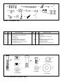
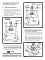
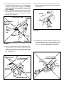
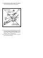
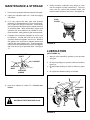
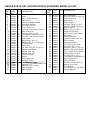
OWNERS
MANUAL
FLO W R ATE
xxxxxxxxxxxxxxxxx
xxxxxxxxxxxxxxxxxxxx
xx
xxxxxxxxxxxxxxxxxxxx
xxxxxxxxxxxxxxxxxxxx
xxx
xxxxxxxxxxxxxxxxxxxx
xxxxxxxxxxxxxxxxxxxx
x
xxxxxxxxxxxxxxxxxxxx
xxxxxxxxxxxxxxxxxxxx
xxxxx
xxxxx
xxxxxxxxxxxxxxxx
xxxxx
xxxxx
xxxxx
xxxxxx
xxxxxx
xxxxxx
xxx
xxx
xxx
xxxxxx
xxxxx
xxxxxx
Model No.
45-0187
BROADCAST SPREADER 160
CAUTION:
Read Rules for
Safe Operation
and Instructions
Carefully
Assembly
Operation
Maintenance
Repair Parts
303 WEST RAYMOND
PRINTED IN USA
SULLIVAN, ILLINOIS 61951
RULES FOR SAFE OPERATIONS
Remember, any power equipment can cause injury if operated improperly or if the user does not understand how
to operate the equipment.
LOOK FOR THIS SYMBOL TO POINT OUT
IMPORTANT SAFETY PRECAUTIONS. IT
MEANS -- ATTENTION! BECOME ALERT! YOUR
SAFETY IS INVOLVED.
Exercise caution at all times when using power equipment.
1. Read the owners manual and know how to operate your tractor, before using the spreader attachment.
2. Never operate tractor and spreader attachment without wearing substantial footwear, and do not allow anyone
to ride or sit on spreader attachment frame.
3. Never allow children to operate the tractor or spreader attachment, and do not allow adults to operate without
proper instructions.
4. Always begin with the transmission in first (low) gear and engine at low speed, and gradually increase speed
as conditions permit.
5. When towing broadcast spreader do not drive too close to a creek or ditch and be alert for holes and other
hazards which could cause you to loose control of the broadcast spreader and tractor.
6. Before operating vehicle on any grade (hill) refer to the safety rules in the vehicle owner's manual concerning
safe operation on slopes. Stay off steep slopes.
7. Read instructions and caution notes for handling/spreading of materials purchased for spreading.
8. Follow maintenance and lubrication instructions as outlined in this manual.
Your broadcast spreader carton contains parts as
shown in figure 1. The hardware package contains
parts shown in figure 2 on page 3. Identify all parts
and layout as shown in figures 1 and 2.
CARTON CONTENTS
LOOSE PARTS IN CARTON
1.
2.
3.
4.
5.
Hitch Tube
Braces
Flow Control Mount Bracket
Flow Control Gauge
Flow Control Arm
6.
7.
8.
9.
10.
11.
Flow Control Rod
Hitch Bracket
Wheels (R.H. and L.H.)
Hopper Assembly
Hopper Cover
Hardware Packeage (not shown)
CARTON CONTENTS
1
7
5
6
3
2
4
8
10
FIGURE 1
9
A
B
F
H
G
D
C
I
E
J
K
N
P
L
O
M
FIGURE 2 - HARDWARE PACK
KEY
A
B
C
D
E
F
G
H
QTY.
6
8
1
1
1
3
2
2
DESCRIPTION
KEY
Hex Bolt 1/4-20 x 1-3/4" Long
Hex Lock Nuts 1/4-20 Thread
Hand Knob
Nylon Washer
Cotter Pin 3/32" x 3/4" Long
Flat Washer 1/4" Standard
Hex Bolts 3/8-16 x 1-1/4" Long
Lock Washers 3/8" I.D.
I
J
K
L
M
N
O
P
QTY.
2
2
4
1
2
1
1
1
DESCRIPTION
Hex Lock Nuts 3/8-16 Thread
Spacers
Flat Washers 1-5/8" O.D.
Grip
Hex Bolt 1/4-20 x 5/8" Long
Flow Control Link
Extension Spring
Cotter Pin 1/8 x 1-1/2" Long
I
A
H
3/8" LOCK NUT
M
G
3/8" LOCK WASHER
B
1/4"x 5/8"
1/4" LOCK NUT
D
F
3/8" x 1-1/4"
K
1/4"x 1-3/4"
1/4" WASHER
NYLON WASHER
FULL SIZE HARDWARE REFERENCE CHART
25/32" WASHER
ASSEMBLY INSTRUCTIONS
TOOLS REQUIRED FOR ASSEMBLY
(1)
(2)
(2)
Pliers
Open or Boxed End Wrench
9/16" Open or Boxed End Wrench
3/8" LOCK
NUT
3/8" FLAT
WASHER
CROSSOVER
TUBE
1. Remove the spreader, loose parts and hardware
package from the carton. See figures 1 and 2.
2. Turn the spreader upside down as shown in figure
3, so that it rests on the hopper.
3. Remove the 3/8" hex bolt, flat washer and hex lock
nut from the center of the crossover tube and shaft
support plate. See figure 3.
HTICH
TUBE
3/8" HEX BOLT,
FLAT WASHER
AND HEX NUT
CROSSOVER
TUBE
3/8" x 2"
HEX BOLT
FIGURE 4
SHAFT
SUPPORT
PLATE
HOPPER
FRAME
5. Assemble two hitch braces to the inside of the
hopper frame, one on each side, using two 1/4" x
1-3/4" and two 1/4" hex lock nuts. See figure 5.
DO NOT TIGHTEN AT THIS TIME.
6. Align the holes in the ends of the two hitch braces
with the nearest hole in the hitch tube, secure with
1/4" x 1-3/4" hex bolt and 1/4" hex lock nut. See
figure 5.
7. Tighten all hex nuts and bolts, following same
sequence as assembled in steps 4, 5 and 6. DO
NOT COLLAPSE TUBE WHEN TIGHTENING.
8. Assemble one spacer, and one 1-5/8" dia. flat
washer to each side of axle. See figure 5.
AXLE
FIGURE 3
4. Place the hitch tube up against the crossover
tube, align the holes in the hitch tube, crossover
tube and shaft support plate, assemble with 3/8"
hex bolt, 3/8" flat washer and 3/8" hex lock nut,
removed in step 3. See figures 3 and 4. MAKE
ONLY FINGER TIGHT AT THIS TIME.
1/4" LOCK
NUT
SPACER
NOTE
WHEN SPREADER IS UP SIDE DOWN,
AS SHOWN IN FIGURE 4, HITCH TUBE
IS UNDERNEATH CROSSOVER TUBE
1-5/8" DIA.
FLAT
WASHER
1/4" x 1-3/4"
HEX BOLT
FIGURE 5
9. Place wheel assembly without hole through hub
(air valve to the outside) onto axle end having the
smallest and secure with 1-5/8" dia. flat washer
and 1/8" x 1-1/2" cotter pin. See figure 6. Use
extra 1-5/8" diameter flat washer if needed to take
up play.
AXLE
11. Turn the broadcast spreader over so that it rests
on its wheels.
12. Assemble the hitch bracket to the hitch tube. See
figure 8. Secure with two 3/8" x 1-1/4" hex bolts,
3/8" lock washers and 3/8" lock nuts. See figure
8.
3/8" x 1-1/4" HEX BOLT
1-5/8" DIA.
FLAT WASHER
HITCH TUBE
3/8" LOCK WASHERS
3/8" HEX LOCK NUTS
COTTER
PIN
HITCH BRACKET
AIR
VALVE
FIGURE 6
10. Place the drive wheel onto the axle (air valve to
the outside) and secure with 1/4" 1-3/4" hex bolt
and 1/4" hex lock nut. See figure 7.
FIGURE 8
13. Assemble the flow control link (the end with the
smallest hole) to the flow control arm using one
1/4" x 5/8" hex bolt and one 1/4" hex lock nut. See
figure 9. DO NOT OVER TIGHTEN, FLOW CONTROL LINK MUST PIVOT FREELY.
14. Place the vinyl grip on the flow control arm. See
figure 9.
VINYL GRIP
1/4" x 1-3/4" HEX BOLT
FLOW
CONTROL
LINK
1/4" HEX
LOCK
NUT
DRIVE WHEEL
AIR VALVE
1/4" HEX LOCK NUT
FIGURE 7
SMALLEST HOLE
FIGURE 9
FLOW
CONTROL
ARM
1/4" x 5/8"
HEX BOLT
15. Assemble the flow control arm to the flow control
mounting bracket using one 1/4" x 5/8" hex bolt
and one 1/4" hex lock nut. See figure 10. DO NOT
OVER TIGHTEN FLOW CONTROL ARM MUST
PIVOT FREELY.
16. Hook one end of extension spring through small
hole near bend in flow control rod and the other
end through the hole in flow control mounting
bracket. See figure 10.
FLOW CONTROL ARM
18. Hook free end of flow control rod through hole in
slide gate bracket located near bottom of hopper.
See figure 12.
SLIDE
GATE
BRACKET
HOPPER
FLOW
CONTROL
LINK
FLOW CONTROL
MOUNTING
BRACKET
FLOW
CONTROL
ROD
FLOW
CONTROL
ROD
FIGURE 12
EXTENSION
SPRING
1/4" LOCK NUT
1/4" x 5/8"
HEX BOLT
FIGURE 10
19. Assemble flow control mounting bracket to the
hitch tube using two 1/4" x 1-3/4" hex bolts, two 1/
4" flat washers and two 1/4" hex lock nuts. See
figure 13. DO NOT TIGHTEN AT THIS TIME.
17. Place 1/4" flat washer on end of flow control link,
align with slot in flow control mounting bracket
and insert end of flow control rod through slot and
hole in flow control link. Secure with 3/32" cotter
pin. See figure 11.
FLOW CONTROL
ROD
FLOW CONTROL
MOUNTING BRACKET
FLOW CONTROL
MOUNTING BRACKET
1/4" x 3/4"
HEX BOLTS
1/4" HEX
LOCK NUTS
1/4" FLAT
WASHER
1/4" FLAT
WASHERS
3/32" COTTER
PIN
FLOW CONTROL LINK
FIGURE 11
FIGURE 13
20. Assemble the flow control gauge onto the flow
control mounting bracket as shown in figure 14.
Secure with nylon washer and hand knob.
PLASTIC KNOB
OFF
NYLON
WASHER
FLOW
CONTROL
GAUGE
FLOW
CONTROL
ARM
FLOW CONTROL
MOUNTING BRACKET
FIGURE 14
21. Move flow control arm to off position and slide flow
control mounting bracket toward hopper until closure plate (located in bottom of hopper) is completely closed. Tighten 1/4" hex lock nuts assembled in step 19. See figure 14.
22. Pre-lubricate per lubrication section on page 9
before operating spreader.
OPERATION
MATERIAL
The application spray pattern should overlap to insure
uniform coverage at the edges. The approximate
distance between each pass is shown in the application diagram. See figure 15.
APPLICATION DIAGRAM
TYPE
Flow Rate Setting
At 3 M.P.H.
Light
Heavy
FERTILIZER
Granular
Pelleted
3
5
5
7
GRASS SEED
Fine
Coarse
2
6
4
8
ICE MELTER
Granular
Pelleted
6
6
8
8
8' to
10'
1. Determine approximate square footage of area to
be covered and estimate amount of material required.
OVERLAP
2. With flow control arm in the off position, set flow
rate gauge at the number indicated in flow rate
chart - light or heavy application rate. Also refer
to the bag instructions for manufacturers recommended settings.
FIGRUE 15
FLOW RATE ADJUSTMENT
(SEE FIGURE 16)
1. Push back on the flow control arm to the off
position and pull forward to the on position. The
higher the number on the flow rate gauge the
larger the opening in the bottom of the hopper.
2. REFER TO FLOW RATE CHART AND INSTRUCTIONS ON FERTILIZER BAG TO SELECT
PROPER FLOW RATE SETTING.
3. Loosen the hand knob to set the flow gauge to the
desired flow setting and tighten the hand knob.
4. Always move flow control arm to off position before stopping or turning spreader.
5. The spreader should be moving before you move
the flow control arm to the on position.
FLOW CONTROL ARM
FF
O
N
O
1 2
3 4
5 6
7 8
91
0
FLOW RATE GAUGE
FIGURE 16
3. Break up lumpy fertilizer as you fill hopper.
4. To broadcast, always start tractor in motion before opening closure plate. Do not allow tractor
to sit stationary with flow control arm in the on
position. If fertilizer is accidentally deposited to
heavily in a small area, soak down thoroughly with
garden hose or sprinkler to prevent burning of
lawn.
IMPORTANT: Application rates (shown on
chart) are affected by humidity and moisture
content of material (granular and pellet); therefore, minor setting adjustments may be necessary to compensate for this condition. The
rate chart is calculated for light and heavy
application. The faster you drive, the wider the
broadcast width. A variation in speed will
determine the flow rates and width of broadcast.
HAND KNOB
CAUTION
When broadcasting weed control fertilizers make sure broadcast pattern
does not hit evergreen trees, flowers
or shrubs.
MAINTENANCE & STORAGE
1. Do not store spreader with any material in hopper.
6. Heavy moisture conditions may require a cover
over the hopper to keep contents dry. The vinyl
cover acts as a wind and moisture shield, but
should not be used as a rain cover. See figure 18.
2. Clean your spreader after use. Flush thoroughly
with water.
VINYL
COVER
3. If for any reason the axle, gear and sprocket
assembly is disassembled, be sure to mark position of parts as they are removed. Drive wheel
and sprocket position determine relation direction
of spreader plate. With reassembly of gear and
sprocket use shim washers as needed for minimum backlash. Add grease to gear and sprocket.
4. If agitator wire becomes damaged or worn it can
be replaced. Loosen 3/8" lock nut on the top of
sprocket shaft until agitator wire is free. Remove
old agitator wire from hole in agitator sleeve and
replace with new agitator wire. Position agitator
wire so that sprocket shaft turns freely and tighten
3/8" lock nut on top of sprocket shaft. See figure
17.
FLO W R ATE
xxxxxxxxxx
xxxxxxxxxxxxxxxxxxxxxxxxxxx
xxxxxxxxxxxxxxx
xxxxxxxxxxxxxxxxxxxxxxxxxxx
xxxxxxxxxxxxxxxx
xxxxxxxxxxxxxxxxxxxxxxxxxxx
xxxxxxxxxxxxxx
xxxxxxxxxxxxxxxxxxxxxxxxxxx
xxxxx
xxxxx
xxxxxxxxxxxxxxxx
xxxxx
xxxxx
xxxxx
xxxxxx
xxxxxx
xxxxxx
xxx
xxx
xxx
xxxxxx
xxxxx
xxxxxx
FIGURE 18
LUBRICATION
(SEE FIGURE 19)
SPROCKET
SHAFT
1. Apply a little automotive grease to the sprocket
and gear.
3/8" LOCKNUT
AGITATOR
WIRE
AGITATOR
SLEEVE
2. Oil nylon bushings on sprocket shaft as shown in
figure 19.
3. Oil axle/shaft bushing on axle as shown in figure
19.
4. Oil right hand wheel bearing as needed.
FIGURE 17
OIL
5. Keep tires inflated to 15-20 P.S.I. Do not over
inflate.
SPROCKET
SHAFT
GREASE
MAXIMUM TIRE PRESSURE 30 PSI
OIL
FIGURE 19
OIL
REPAIR PARTS BROADCAST SPREADER MODEL 45-0187
56
58
40
37
60
39
9
1
xxxxx
xxxxx
R AT E x
F LO W xxxxxxxxxxxxxxxxxx
xxx
xxx
xxx
xxxxxxxxx
xxxxxxxxx
xxxx
xxxxxxxxx xxxxxxxxxxxx xxxxxxxxxxxx
xxx
xxx
xx
xxxxxxxxx xxxxxxxxxxxx xxxxxxxxxxxx
xxx
xxx
xxxxxxxxx xxxxxxxxxxxx
xxx
xxxxxxxxx
37
xxxxx
xxxxx
xxxxxx
xxx
xxxxxx
7
40
9 57
31
A
40
9
53
B
58
3
A
28
9
34
45
54
48
61
33
10
E
12
B
19
43
7
45
ON
D
32
29
44
52
39
C
36
C
51
24
9 23
4
9
11
37
35
6
26
27
9
5
39
30
16
xxxxxx
xxx
xxx
4
xxxxxxxx
xxxxxxxx
xxxxxx
xxxxx
xxxxx
xxxxxx
41
49
19
59
42
47
13
38
8
OFF
9
18
24
23
21
20
38
21 22
9
37
E
35
D
50
51
51
37
15
55
7
59
17
14
REPAIR PARTS LIST FOR BROADCAST SPREADER MODEL 45-0187
REF.
NO.
1
2
3
4
5
6
7
8
9
10
11
12
13
14
15
16
17
18
19
20
21
22
23
24
25
26
27
28
29
30
31
PART QTY. DESCRIPTION
NO.
44480
1
Hopper
43882
6
Rivet
62482
1
Ass'y - Guide Closure
44462
1
Tube Frame
23753
1
Slide Gate Angle Bracket
23758
1
Slide Gate Bracket
43082
5
Nut, Hex Lock 3/8"
23756
1
Flow Control Link
43013
18
Nut, Hex Lock 1/4-20 Thread
43808
1
Tube Crossover
43084
2
Bolt, Hex 5/16" x 1-3/4"
43086
2
Lock Washer, Spring 5/16" ID
43064
2
Nut, Hex Lock 5/16-18 Thread
44487
1
Tube, Hitch
44458
1
Wheel, Ass'y 16" x 4"
44459
1
Wheel, Ass'y 16" x 4" W/ Hole
23687
1
Bracket, Hitch
23522
1
Shaft, Axle
43851
2
Pin, Roll 3/16" Dia. x 1.25" Lg.
43871
1
Bushing, Axle/Shaft
1540-032 5
Washer, Flat .78"
1540-162 1
Washer, Std. 3/4"
44798
2
Bearing Flange
44474
2
Spacer
23524
1
Shaft, Sprocket
04367
1
Spreader Plate
43850
1
Pin, 1/8" x 5/8" Spring
44468
1
Sprocket - 6T
43852
1
Bushing, Nylon .375 ID
23766
1
Sleeve Agitator
43878
1
Wire, Agitator
REF.
NO.
PART
NO.
32
33
34
35
36
37
38
39
40
41
42
43
44
45
46
47
48
49
50
51
52
53
54
55
56
57
58
59
60
61
43070
41576
44469
23525
23762
1509-069
43866
1543-069
43088
23755
62732
62474
23757
44101
23533
43000
43848
43087
43093
43009
43849
44285
43054
43003
43962
44566
43012
R19111116
23697
46055
44659
QTY. DESCRIPTION
3
2
1
2
1
12
2
9
9
1
1
1
1
1
1
1
1
2
1
4
1
1
1
2
1
1
3
3
1
1
1
3/8" Flat Washer
Bolt, Hex 3/8-16 x 1-3/4" Lg.
Flow Control Rod
Brace, Hitch
Shaft, Support
Bolt, Hex 1/4-20 x 1-3/4"
Bolt, Hex 1/4-20 x 5/8" Lg.
Washer, Nylon
Washer, Flat 1/4" Std
Gauge, Flow Control
Ass'y. Flow Control Mount
Ass'y Gear
Flow Control Arm
Cotter Pin 3/32" x 3/4" Lg.
Plate, Closure
Spring, Extension
Grip, Flow Control Arm
Bolt, Hex 3/8" x 1-1/4"
Cotter Pin, 1/8" x 1-1/2" Lg.
Washer 1-5/8" OD x 25/32"
Knob, Plastic 1/4-20 Thread
Bushing Derlin .375 ID
Bolt, Hex 3/8" x 2" Lg.
Lock Washer, Spring 3/8" ID
Vinyl Hopper Cover
Spring, Torsion
Bolt, Hex 1/4-20 x 3/4" Lg.
Washer, 5/16" SAE
Strap, Hopper
Pin, 1/8" Dia. x 1" Lg. Spring
Owner's Manual
REPAIR PARTS
303 West Raymond
Sullivan, Il. 61951
217-728-8388