1
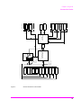
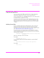
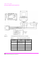
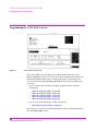
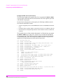
Agilent Technologies 8920A
RF Communications Test Set
Programmer’s Guide
Firmware Version A.18.00 and above
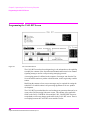
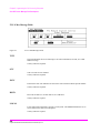
SCREEN CONTROL
INSTRUMENT STATE
MSSG
HELP
CONFI
HOLD
PRINT
ADRS
SAVE
RX
TX
DUPLE
PREV
TESTS
LOCAL
RECAL
USER
DATA FUNCTIONS
k1’
REF
INCR
k1
k2’
METER
INCR
LO
MEAS
PRESE
DATA
AVG
INCR
7
8
9
ENTER
4
5
6
GHz
1
2
3
HI
dB
k2
k3’
CURSOR CON-
k3
ASSIG
k4
RELEA
SHIFT
CANCE
+_
0
PUSH TO
k5
YES
NO
ON/OFF
ppm
Ω
%
%
MHz
s
kHz
ms
Hz
MEMO
RF IN/OUT
DUPLEX OUT
ANT IN
MIC/
VOL-
SQUELC
AUDIO IN
AUDIO
HI
LO
POWE
OF
O
!
MAX POWER
!
!
MAX POWER 200
MAX
!
MAX
Agilent Part No. 08920-90220
Printed in U. S. A.
April 2000
Rev. B
1
© Copyright Agilent Technologies 1997, 2000
Notice
No part of this manual may be reproduced in any form or by any means (including
electronic storage and retrieval or translation into a foreign language) without prior
agreement and written consent from Agilent Technologies Inc. as governed by
United States and international copyright laws.
The material contained in this document is subject to change without notice.
Agilent Technologies makes no warranty of any kind with regard to this material,
including, but not limited to, the implied warranties of merchantability and fitness
for a particular purpose. Agilent Technologies Inc. shall not be liable for errors
contained herein or for incidental or consequential damages in connection with the
furnishing, performance, or use of this material.
U.S. Government users will receive no greater than Limited Rights as defined in
FAR 52.227-14 (June 1987) or DFAR 252.227-7015 (b)(2) (November 1995), as
applicable in any technical data.
Agilent Technologies
Learning Products Department
24001 E. Mission
Liberty Lake, WA 99019-9599
U.S.A.
Edition/Print Date
All Editions and Updates of this manual and their creation dates are listed below.
Rev. A . . . . . December 1997
Rev. B . . . . . April 2000
2
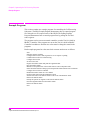
Safety Summary
The following general safety precautions must be observed during all phases of
operation of this instrument. Failure to comply with these precautions or with
specific warnings elsewhere in this manual violates safety standards of design,
manufacture, and intended use of the instrument. Agilent Technologies Inc.
assumes no liability for the customer’s failure to comply with these requirements.
GENERAL
This product is a Safety Class 1 instrument (provided with a protective earth
terminal). The protective features of this product may be impaired if it is used in a
manner not specified in the operation instructions.
All Light Emitting Diodes (LEDs) used in this product are Class 1 LEDs as per IEC
60825-1.
This product has been designed and tested in accordance with IEC Publication
1010, "Safety Requirements for Electronic Measuring Apparatus," and has been
supplied in a safe condition. This instruction documentation contains information
and warnings which must be followed by the user to ensure safe operation and to
maintain the product in a safe condition.
ENVIRONMENTAL CONDITIONS
This instrument is intended for indoor use in an installation category II, pollution
degree 2 environment. It is designed to operate at a maximum relative humidity of
95% and at altitudes of up to 2000 meters. Refer to the specifications tables for the
ac mains voltage requirements and ambient operating temperature range.
Ventilation Requirements: When installing the product in a cabinet, the convection
into and out of the product must not be restricted. The ambient temperature
(outside the cabinet) must be less than the maximum operating temperature of the
product by 4° C for every 100 watts dissipated in the cabinet. If the total power
dissipated in the cabinet is greater than 800 watts, then forced convection must be
used.
BEFORE APPLYING POWER
Verify that the product is set to match the available line voltage, the correct fuse is
installed, and all safety precautions are taken. Note the instrument's external
markings described under Safety Symbols.
3
GROUND THE INSTRUMENT
To minimize shock hazard, the instrument chassis and cover must be connected to
an electrical protective earth ground. The instrument must be connected to the ac
power mains through a grounded power cable, with the ground wire firmly
connected to an electrical ground (safety ground) at the power outlet. Any
interruption of the protective (grounding) conductor or disconnection of the
protective earth terminal will cause a potential shock hazard that could result in
personal injury.
FUSES
Only fuses with the required rated current, voltage, and specified type (normal
blow, time delay, etc.) should be used. Do not use repaired fuses or short-circuited
fuse holders. To do so could cause a shock or fire hazard.
DO NOT OPERATE IN AN EXPLOSIVE ATMOSPHERE
Do not operate the instrument in the presence of flammable gases or fumes.
DO NOT REMOVE THE INSTRUMENT COVER
Operating personnel must not remove instrument covers. Component replacement
and internal adjustments must be made only by qualified service personnel.
Instruments that appear damaged or defective should be made inoperative and
secured against unintended operation until they can be repaired by qualified
service personnel.
WARNING:
The WARNING sign denotes a hazard. It calls attention to a procedure, practice, or
the like, which, if not correctly performed or adhered to, could result in personal
injury. Do not proceed beyond a WARNING sign until the indicated conditions are
fully understood and met.
CAUTION:
The CAUTION sign denotes a hazard. It calls attention to an operating procedure, or the
like, which, if not correctly performed or adhered to, could result in damage to or
destruction of part or all of the product. Do not proceed beyond a CAUTION sign until the
indicated conditions are fully understood and met.
4
Safety Symbols
Caution, refer to accompanying documents
Warning, risk of electric shock
Earth (ground) terminal
Alternating current
Frame or chassis terminal
Standby (supply). Units with this symbol are not completely disconnected from ac
mains when this switch is off.
To completely disconnect the unit from ac mains, either disconnect the power cord,
or have a qualified electrician install an external switch.
Product Markings CE - the CE mark is a registered trademark of the European Community. A CE
mark accompanied by a year indicated the year the design was proven.
CSA - the CSA mark is a registered trademark of the Canadian Standards
Association.
CERTIFICATION Agilent Technologies certifies that this product met its published specifications at
the time of shipment from the factory. Agilent Technologies further certifies that its
calibration measurements are traceable to the United States National Institute of
Standards and Technology, to the extent allowed by the Institute’s calibration
facility, and to the calibration facilities of other International Standards
Organization members
5
Agilent Technologies Warranty Statement for Commercial Products
Agilent Technologies 8920A RF Communications Test Set
Duration of
Warranty: 1 year
1. Agilent Technologies warrants Agilent Technologies hardware, accessories and
supplies against defects in materials and workmanship for the period specified above.
If Agilent Technologies receives notice of such defects during the warranty period,
Agilent Technologies will, at its option, either repair or replace products which prove
to be defective. Replacement products may be either new or like-new.
2
Agilent Technologies warrants that Agilent Technologies software will not fail to
execute its programming instructions, for the period specified above, due to defects in
material and workmanship when properly installed and used. If Agilent Technologies
receives notice of such defects during the warranty period, Agilent Technologies will
replace software media which does not execute its programming instructions due to
such defects.
3. Agilent Technologies does not warrant that the operation of Agilent Technologies
products will be uninterrupted or error free. If Agilent Technologies is unable, within
a reasonable time, to repair or replace any product to a condition as warranted,
customer will be entitled to a refund of the purchase price upon prompt return of the
product.
4
Agilent Technologies products may contain remanufactured parts equivalent to new in
performance or may have been subject to incidental use.
5. The warranty period begins on the date of delivery or on the date of installation if
installed by Agilent Technologies. If customer schedules or delays Agilent
Technologies installation more than 30 days after delivery, warranty begins on the 31st
day from delivery.
6
6
Warranty does not apply to defects resulting from (a) improper or inadequate
maintenance or calibration, (b) software, interfacing, parts or supplies not supplied by
Agilent Technologies, (c) unauthorized modification or misuse, (d) operation outside
of the published environmental specifications for the product, or (e) improper site
preparation or maintenance.
7
TO THE EXTENT ALLOWED BY LOCAL LAW, THE ABOVE WARRANTIES
ARE EXCLUSIVE AND NO OTHER WARRANTYOR CONDITION, WHETHER
WRITTEN OR ORAL IS EXPRESSED OR IMPLIED AND AGILENT
TECHNOLOGIES SPECIFICALLY DISCLAIMS ANY IMPLIED WARRANTIES
OR CONDITIONS OR MERCHANTABILITY, SATISFACTORY QUALITY, AND
FITNESS FOR A PARTICULAR PURPOSE.
8. Agilent Technologies will be liable for damage to tangible property per incident up to
the greater of $300,000 or the actual amount paid for the product that is the subject of
the claim, and for damages for bodily injury or death, to the extent that all such damages are determined by a court of competent jurisdiction to have been directly caused
by a defective Agilent Technologies product.
9. TO THE EXTENT ALLOWED BY LOCAL LAW, THE REMEDIES IN THIS
WARRANTY STATEMENT ARE CUSTOMER’S SOLE AND EXCLUSIVE
REMEDIES. EXCEPT AS INDICATED ABOVE, IN NO EVENT WILL AGILENT
TECHNOLOGIES OR ITS SUPPLIERS BE LIABLE FOR LOSS OF DATA OR FOR
DIRECT, SPECIAL, INCIDENTAL, CONSEQUENTIAL (INCLUDING LOST
PROFIT OR DATA), OR OTHER DAMAGE, WHETHER BASED IN CONTRACT,
TORT, OR OTHERWISE.
FOR CONSUMER TRANSACTIONS IN AUSTRALIA AND NEW ZEALAND:
THE WARRANTY TERMS CONTAINED IN THIS STATEMENT, EXCEPT TO
THE EXTENT LAWFULLY PERMITTED, DO NOT EXCLUDE RESTRICT OR
MODIFY AND ARE IN ADDITION TO THE MANDATORY STATUTORY
RIGHTS APPLICABLE TO THE SALE OF THIS PRODUCT TO YOU.
ASSISTANCE
Product maintenance agreements and other customer assistance agreements are
available for Agilent Technologies products. For any assistance, contact your
nearest Agilent Technologies Sales and Service Office.
7
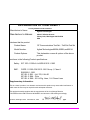
DECLARATION OF CONFORMITY
according to ISO/IEC Guide 22 and EN 45014
Manufacturer’s Name:
Manufacturer’s Address:
Agilent Technologies
24001 E. Mission Avenue
Liberty Lake, Washington 99019-9599
USA
declares that the product
Product Name:
RF Communications Test Set / Cell Site Test Set
Model Number:
Agilent Technologies 8920A, 8920B , and 8921A
Product Options:
This declaration covers all options of the above
product.
conforms to the following Product specifications:
Safety: IEC 1010-1:1990+A1+A2/EN 61010-1:1993
EMC:
CISPR 11:1990 / EN 55011:1991 Group 1, Class A
EN 50082-1 : 1992
IEC 801-2:1991 - 4 kV CD, 8 kV AD
IEC 801-3:1984 - 3V/m
IEC 801-4:1988 - 0.5 kV Sig. Lines, 1 kV Power Lines
Supplementary Information:
This is a class A product. In a domestic environment this product may cause radio interference in
which case the user may be required to take adequate measures.
This product herewith complies with the requirements of the Low Voltage Directive
73/23/EEC and the EMC Directive 89/336/EEC and carries the CD-marking accordingly.
Spokane, Washington USA
8
November 20, 1998
Vince Roland/Quality Manager
Table 1
Regional Sales Offices
United States of America:
Agilent Technologies
Test and Measurement Call Center
P.O. Box 4026
Englewood, CO 80155-4026
Canada:
Agilent Technologies Canada Inc.
5150 Spectrum Way
Mississauga, Ontario
L4W 5G1
(tel) 1 800 452 4844
(tel) 1 877 894 4414
Europe:
Agilent Technologies
European Marketing Organization
P.O. Box 999
1180 AZ Amstelveen
The Netherlands
(tel) (3120) 547 9999
Japan:
Agilent Technologies Japan Ltd.
Measurement Assistance Center
9-1 Takakura-Cho, Hachioji-Shi,
Tokyo 192-8510, Japan
(tel) (81) 456-56-7832
(fax) (81) 426-56-7840
Latin America:
Agilent Technologies
Latin America Region
Headquarters
5200 Blue Lagoon Drive,
Suite #950
Miami, Florida 33126
U.S. A.
(tel) (305) 267 4245
(fax) (305) 267 4286
Australia/New Zealand:
Agilent Technologies
Australia Pty Ltd.
347 Burwood Highway
Forest Hill, Victoria 3131
Australia
(tel) 1 800 629 485
(fax) (61 3) 9272 0749
New Zealand
(tel) 0 800 738 378
(fax) (64 4) 802 6881
Asia Pacific:
Agilent Technologies
24/F, Cityplaza One,
111 Kings Road,
Taikoo Shing, Hong Kong
(tel) (852) 3197 7777
(fax) (852) 2506 9233
9
Service and
Support
Any adjustment, maintenance, or repair of this product must be performed by
qualified personnel. Contact your customer engineer through your local Agilent
Technologies Service Center. You can find a list of local service representatives on
the Web at:
http://www.agilent-tech.com/services/English/index.html
If you do not have access to the Internet, one of these centers can direct you to your
nearest representative:
Table 2
10
United States Test and Measurement Call Center
(Toll free in US)
(800) 452-4844
Europe
(31 20) 547 9900
Canada
(905) 206-4725
Japan Measurement Assistance Center
(81) 426 56 7832
|(81) 426 56 7840 (FAX)
Latin America
(305) 267 4288 (FAX)
Australia/New Zealand
1 800 629 485 (Australia)
0800 738 378 (New Zealand)
Asia-Pacific
(852) 2599 7777
(852) 2506 9285 (FAX)
Manufacturer’s
Declaration
This statement is provided to comply with the requirements of the German Sound
Emission Directive, from 18 January 1991.
This product has a sound pressure emission (at the operator position) < 70 dB(A).
•
•
•
•
Sound Pressure Lp < 70 dB(A).
At Operator Position.
Normal Operation.
According to ISO 7779:1988/EN 27779:1991 (Type Test).
Herstellerbescheinigung
Diese Information steht im Zusammenhang mit den Anforderungen der
Maschinenlärminformationsverordnung vom 18 Januar 1991.
•
•
•
•
In this Book
Schalldruckpegel Lp < 70 dB(A).
Am Arbeitsplatz.
Normaler Betrieb.
Nach ISO 7779:1988/EN 27779:1991 (Typprüfung).
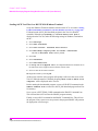
Chapter 1, Using HP-IB, describes the general guidelines for using HP-IB and how to
prepare the Test Set for HP-IB usage. This chapter includes example programs for
controlling the basic functions of the Test Set.
Chapter 2, Methods For Reading Measurement Results, contains guidelines for
programming the test set for returning measurement results. Topics discussed include how
to recover from a "hung" state when a measurement fails to complete. Sample code is
included.
Chapter 3, HP-IB Command Guidelines, contains information about sequential and
overlapped commands, command syntax, units of measure, and measurement states. A
short example program is also presented to familiarize the user with remote operation of
the Test Set.
Chapter 4, HP-IB Commands, contains command syntax diagrams, equivalent
front-panel key commands, IEEE 488.2 Common Commands and triggering
commands.
Chapter 5, Advanced Operations, includes information about increasing measurement
throughput, status reporting, error reporting, service requests, instrument initialization,
and passing control.
Chapter 6, Memory Cards/Mass Storage, describes the types of mass storage (RAM
disk, ROM disk, external disk drives, SRAM cards, and ROM cards) and the file system
formats (DOS, LIF) available in the Test Set.
11
Chapter 7, IBASIC Controller, describes how to develop Instrument BASIC (IBASIC)
programs for use on the Test Set’s built-in IBASIC Controller. Topics discussed are:
interfacing to the IBASIC Controller using the serial ports, overview of the three program
development methods, entering and editing IBASIC programs, program control using the
PROGram Subsystem, and an introduction to writing programs for the TESTS subsystem.
Chapter 8, Programming the Call Processing Subsystem, describes how to control the
Test Set’s Call Processing Subsystem using the Call Processing Subsystem’s remote user
interface. Topics discussed are: accessing the Call Processing Subsystem screens,
handling error messages, controlling program flow using the Call Processing Status
Register Group, and how to query data messages received from the mobile station.
Example programs are provided showing how to control the Call Processing Subsystem
using service requests and register polling.
Error Messages describes the Text Only HP-IB Errors and the Numbered HP-IB Errors.
This section also describes other types of error messages that the Test Set displays and
where to find more information about those types of error messages.
12
Contents
1 Using GPIB
Overview of the Test Set
Getting Started
34
Remote Operation
Addressing
26
47
49
IEEE 488.1 Remote Interface Message Capabilities
Remote/Local Modes
50
53
13
Contents
2 Methods For Reading Measurement Results
Background 58
HP® BASIC ‘ON TIMEOUT’ Example Program 60
HP® BASIC ‘MAV’ Example Program 64
14
Contents
3 GPIB Command Guidelines
Sequential and Overlapped Commands
Guidelines for Operation
70
71
15
Contents
4 GPIB Commands
GPIB Syntax Diagrams 92
Adjacent Channel Power (ACP)
AF Analyzer
95
97
AF Generator 1
100
AF Generator 2 Pre-Modulation Filters
AF Generator 2/Encoder
Configure, I/O Configure
102
117
Call Processing 122
Decoder
141
Display 145
Measure
147
Oscilloscope
Program
154
159
Save/Recall Registers
RF Analyzer
160
161
RF Generator
Radio Interface
163
164
Spectrum Analyzer
165
GPIB Only Commands 167
16
101
Contents
Status 168
System 169
Tests
Trigger
170
173
Integer Number Setting Syntax
Real Number Setting Syntax
174
175
Multiple Real Number Setting Syntax
Number Measurement Syntax
177
Multiple Number Measurement Syntax
Equivalent Front-Panel Key Commands
IEEE 488.2 Common Commands
Triggering Measurements
176
179
180
208
224
17
Contents
5 Advanced Operations
Increasing Measurement Throughput
Status Reporting
239
GPIB Service Requests
Instrument Initialization
Passing Control
18
313
293
303
234
Contents
6 Memory Cards/Mass Storage
Default File System
324
Mass Storage Device Overview
325
Default Mass Storage Locations
331
Mass Storage Access
333
DOS and LIF File System Considerations
Using the ROM Disk
340
Using Memory Cards
341
Backing Up Procedure and Library Files
Copying Files Using IBASIC Commands
Using RAM Disk
334
346
347
349
Using External Disk Drives
351
19
Contents
7 IBASIC Controller
Introduction
354
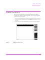
The IBASIC Controller Screen
355
Important Notes for Program Development
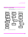
Program Development
357
358
Interfacing to the IBASIC Controller using Serial Ports
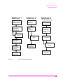
Choosing Your Development Method
360
373
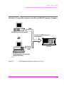
Method #1. Program Development on an External BASIC Language
Computer 375
Method #2. Developing Programs on the Test Set Using the IBASIC
EDIT Mode 381
Method #3. Developing Programs Using Word Processor on a PC
(Least Preferred) 385
Uploading Programs from the Test Set to a PC
Serial I/O from IBASIC Programs
PROGram Subsystem
The TESTS Subsystem
20
396
419
393
392
Contents
8 Programming the Call Processing Subsystem
Description of the Call Processing Subsystem’s Remote User
Interface 426
Using the Call Processing Subsystem’s Remote User Interface 429
Programming the CALL CONTROL Screen 439
Programming the CALL DATA Screen 464
CALL DATA Screen Message Field Descriptions 468
Programming the CALL BIT Screen 478
CALL BIT Screen Message Field Descriptions 487
Programming the ANALOG MEAS Screen 510
Programming the CALL CONFIGURE Screen 517
Example Programs 520
21
Contents
9 Error Messages
22
Contents
Index 569
23
Contents
24
1
Using GPIB1
1. GPIB was formerly called HP-IB for Hewlett-Packard instruments. Some labels on
the instrument may still reflect the former HP® name.
25
Chapter 1, Using GPIB
Overview of the Test Set
Overview of the Test Set
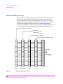
The Test Set combines up to 22 separate test instruments and an Instrument
BASIC (IBASIC) Controller into one package. All of the Test Set’s functions can
be automatically controlled through application programs running on the built-in
IBASIC Controller or on an external controller connected through GPIB.
Developing programs for the Test Set is simplified if the programmer has a basic
understanding of how the Test Set operates. An overview of the Test Set’s
operation is best presented in terms of how information flows through the unit.
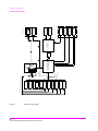
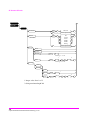
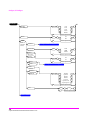
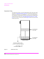
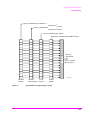
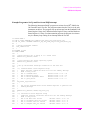
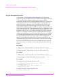
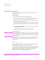
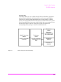
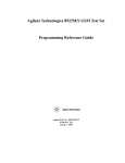
The simplified block diagrams shown in Figure 1 on page 32 and Figure 2 on page
33 depict how instrument control information and measurement result information
are routed among the Test Set’s instruments, instrument control hardware, built-in
IBASIC controller, and other components.
The Test Set has two operating modes: Manual Control mode and Automatic
Control mode. In Manual Control mode the Test Set’s operation is controlled
through the front panel keypad/rotary knob. There are two Automatic Control
modes: Internal and External. In Internal Automatic Control mode the Test Set’s
operation is controlled by an application program running on the built-in IBASIC
Controller. In External Automatic Control mode the Test Set’s operation is
controlled by an external controller connected to the Test Set through the GPIB
interface.
26
S:\agilent\8920\8920b\PRGGUIDE\BOOK\CHAPTERS\usehpib.fb
Chapter 1, Using GPIB
Overview of the Test Set
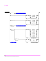
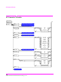
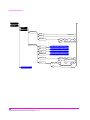
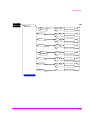
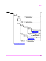
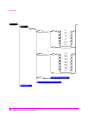
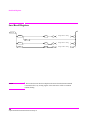
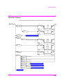
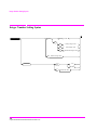
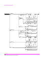
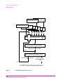
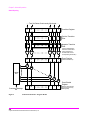
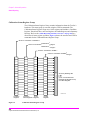
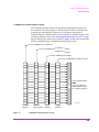
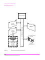
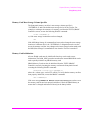
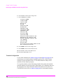
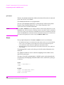
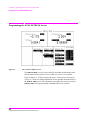
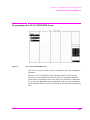
Manual Control Mode
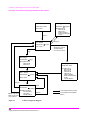
The Test Set’s primary instruments are shown on the left side of Figure 1. There
are two classes of instruments in the Test Set: signal analyzers (RF Analyzer, AF
Analyzer, Oscilloscope, Spectrum Analyzer, Signaling Decoder) and signal
sources (RF Generator, AF Generator #1, AF Generator #2/Signaling Encoder).
The Test Set’s measurement capability can be extended by adding application
specific “top boxes” such as the Agilent 83201A Dual Mode Cellular Adapter.
Since so many instruments are integrated into the Test Set, it is not feasible to
have an actual “front panel” for each instrument. Therefore, each instrument’s
front panel is maintained in firmware and is displayed on the CRT whenever the
instrument is selected. Only one instrument front panel can be displayed on the
CRT at any given time (up to four measurement results can be displayed
simultaneously if desired). Just as with stand alone instruments, instrument front
panels in the Test Set can contain instrument setting information, measurement
result(s), or data input from the DUT.
Using the Test Set in Manual Control mode is very analogous to using a set of
bench or rack-mounted test equipment. To obtain a measurement result with a
bench or racked system, the desired measurement must be “active.” For example,
if an RF power meter is in the bench or racked system and the user wishes to
measure the power of an RF carrier they must turn the power meter on, and look at
the front panel to see the measurement result. Other instruments in the system
may be turned off but this would not prevent the operator from measuring the RF
power.
Conceptually, the same is true for the Test Set. In order to make a measurement or
input data from a DUT, the desired measurement field or data field must be
“active.” This is done by using the front panel keypad/rotary knob to select the
instrument whose front panel contains the desired measurement or data field and
making sure that the desired measurement or data field is turned ON.
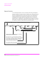
Figure 1 shows that instrument selection is handled by the To Screen control
hardware which routes the selected instrument’s front panel to the CRT for
display. Once an instrument’s front panel is displayed on the CRT, the user can
manipulate the instrument settings, such as turning a specific measurement or data
field on or off, using the keypad/rotary knob. Figure 1 also shows that instrument
setup is handled by the Instrument Control hardware which routes setup
information from the front panel to the individual instruments.
A GPIB/RS-232/Parallel Printer interface capability is available in the Test Set. In
Manual Control mode this provides the capability of connecting an external
GPIB, serial, or parallel printer to the Test Set so that display screens can be
printed.
27
Chapter 1, Using GPIB
Overview of the Test Set
Internal Automatic Control Mode
In Internal Automatic Control mode the Test Set’s operation is controlled by an
application program running on the built-in Instrument BASIC (IBASIC)
Controller. The built-in controller runs programs written in IBASIC, a subset of
the HP® BASIC programming language used on the HP® 9000 Series 200/300
System Controllers. IBASIC is the only programming language supported on the
built-in IBASIC Controller.
Similarities Between the Test Set’s IBASIC Controller and Other Single-Tasking
Controllers
The architecture of the IBASIC Controller is similar to that of other single-tasking
instrumentation controllers. Only one program can be run on the IBASIC
Controller at any given time. The program is loaded into RAM memory from
some type of mass storage device. Five types of mass storage devices are
available to the Test Set: SRAM memory cards, ROM memory cards, external
disk drives connected to the GPIB interface, internal RAM disc, and internal
ROM disc. Three types of interfaces are available for connecting to external
instruments and equipment: GPIB, RS-232, and 16-bit parallel (available as Opt
020 Radio Interface Card).
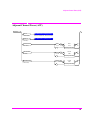
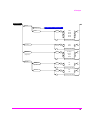
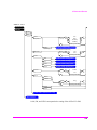
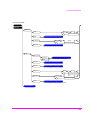
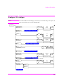
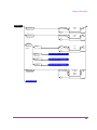
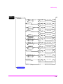
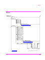
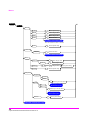
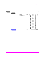
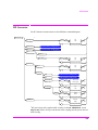
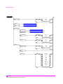
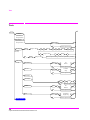
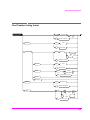
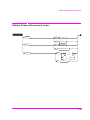
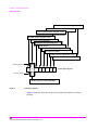
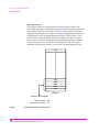
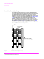
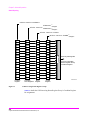
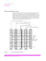
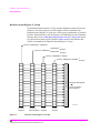
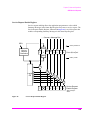
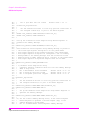
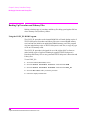
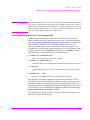
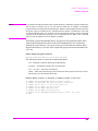
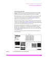
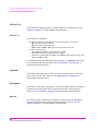
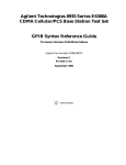
Figure 2 shows how information is routed inside the Test Set when it is in Internal
Automatic Control mode. In Manual Control mode certain Test Set resources are
dedicated to manual operation. These resources are switched to the IBASIC
Controller when an IBASIC program is running. These include the serial interface
at select code 9, the GPIB interface at select code 7, the parallel printer interface at
select code 15, and the CRT. In Manual Control mode, front panel information
(instrument settings, measurement results, data input from the DUT) is routed to
the CRT through the To Screen control hardware. In Internal Automatic Control
mode the measurement results and data input from the DUT are routed to the
IBASIC Controller through a dedicated GPIB interface. Also, in Internal
Automatic Control mode, the CRT is dedicated to the IBASIC Controller for
program and graphics display. This means instrument front panels cannot be
displayed on the CRT when an IBASIC program is running.
28
S:\agilent\8920\8920b\PRGGUIDE\BOOK\CHAPTERS\usehpib.fb
Chapter 1, Using GPIB
Overview of the Test Set
Differences Between the Test Set’s IBASIC Controller and Other Single-Tasking
Controllers
The IBASIC Controller is unlike other single tasking instrumentation controllers
in several ways. First, it does not have a keyboard. This imposes some limitations
on creating and editing IBASIC programs directly on the Test Set. In Internal
Automatic Control mode a “virtual” keyboard is available in firmware which
allows the operator to enter alphanumeric data into a dedicated input field using
the rotary knob. This is not the recommended programming mode for the IBASIC
Controller. This feature is provided to allow user access to IBASIC programs for
short edits or troubleshooting. Several programming modes for developing
IBASIC programs to run on the internal IBASIC Controller are discussed in this
manual.
Secondly, the IBASIC Controller has a dedicated GPIB interface, select code 8 in
Figure 2, for communicating with the internal instruments of the Test Set. This
GPIB interface is only available to the IBASIC Controller. There is no external
connector for this GPIB interface. No external instruments may be added to this
GPIB interface. The GPIB interface, select code 7 in Figure 2, is used to interface
the Test Set to external instruments or to an external controller. The dedicated
GPIB interface at select code 8 conforms to the IEEE 488.2 Standard in all
respects but one. The difference being that each instrument on the bus does not
have a unique address. The Instrument Control Hardware determines which
instrument is being addressed through the command syntax. Refer to Chapter 4,
“GPIB Commands,” for a listing of the GPIB command syntax for the Test Set.
29
Chapter 1, Using GPIB
Overview of the Test Set
External Automatic Control Mode
In External Automatic Control mode the Test Set’s operation is controlled by an
external controller connected to the Test Set through the GPIB interface. When in
External Automatic Control mode the Test Set’s internal configuration is the same
as in Manual Control Mode with two exceptions:
1. Configuration and setup commands are received through the external GPIB interface,
select code 7, rather than from the front-panel keypad/rotary knob.
2. The MEASure command is used to obtain measurement results and DUT data through
the external GPIB interface.
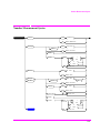
Figure 1 on page 32 shows how information is routed inside the Test Set in Manual
Control mode. Figure 1 on page 32 also shows that certain Test Set resources are
dedicated to the IBASIC Controller (Memory Card, ROM disk, Serial Interface
#10) and are not directly accessible to the user in Manual Control Mode. In
addition, Figure 1 on page 32 shows that Serial Interface #9 and Parallel Printer
Interface #15 are accessible as write-only interfaces for printing in Manual
Control mode. These same conditions are true when in External Automatic
Control mode. If the user wished to access these resources from an external
controller, an IBASIC program would have to be run on the Test Set from the
external controller.
30
S:\agilent\8920\8920b\PRGGUIDE\BOOK\CHAPTERS\usehpib.fb
Chapter 1, Using GPIB
Overview of the Test Set
Writing programs for the Test Set
One of the design goals for automatic control of the Test Set was that it operate the
same way programmatically as it does manually. This is a key point to remember
when developing programs for the Test Set. The benefit of this approach is that to
automate a particular task, one need only figure out how to do the task manually
and then duplicate the same process in software. This has several implications
when designing and writing programs for the Test Set:
1. In Manual Control mode a measurement must be “active” in order to obtain a
measurement result or input data from the DUT. From a programming perspective this
means that before attempting to read a measurement result or to input data from the
DUT, the desired screen for the measurement result or data field must be selected using
the DISPlay command and the field must be in the ON state.
2. In Manual Control mode instrument configuration information is not routed through the
To Screen control hardware block. From a programming perspective this means that
configuration information can be sent to any desired instrument without having to first
select the instrument’s front panel with the DISPlay command.
Keeping these points in mind during program development will minimize
program development time and reduce problems encountered when running the
program.
31
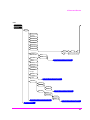
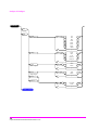
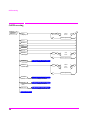
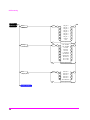
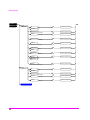
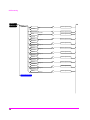
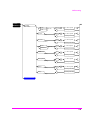
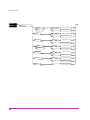
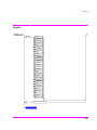
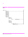
Figure 1
Manual Control Mode
32
S:\agilent\8920\8920b\PRGGUIDE\BOOK\CHAPTERS\usehpib.fb
TOP
BOXES
SIGNALING
DECODER
RF ANALYZER
SPECTRUM
ANALYZER
OSCILLOSCOPE
AF ANALYZER
SIGNALING
ENCODER
FUNCTION
GEN
AF GEN #2
AF GEN #1
RF GEN
TO SCREEN
CONTROL
HARDWARE
INSTRUMENT CONTROL HARDWARE
FRONT
PANEL
INFORMATION
INSTRUMENT
SETUP
INFORMATION
MEASUREMENT RESULTS AND DUT DATA
GPIB
#8
IBASIC
CONTROLLER
GPIB
#7
PARALLEL
PRINTER
#15
SERIAL I/F
#9
SERIAL I/F
#10
ROM DISK
MEMORY CARD
KEYPAD/
ROTARY KNOB
CRT
FRONT PANEL
Chapter 1, Using GPIB
Overview of the Test Set
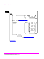
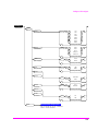
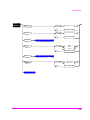
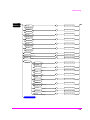
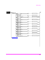
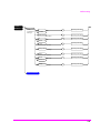
Figure 2
TOP
BOXES
SIGNALING
DECODER
RF ANALYZER
SPECTRUM
ANALYZER
OSCILLOSCOPE
AF ANALYZER
SIGNALING
ENCODER
FUNCTION
GEN
AF GEN #2
AF GEN #1
RF GEN
TO SCREEN
CONTROL
HARDWARE
INSTRUMENT CONTROL HARDWARE
FRONT
PANEL
INFORMATION
INSTRUMENT
SETUP
INFORMATION
MEASUREMENT RESULTS AND DUT DATA
GPIB
#8
IBASIC
CONTROLLER
GPIB
#7
PARALLEL
PRINTER
#15
SERIAL I/F
#9
SERIAL I/F
#10
ROM DISK
MEMORY CARD
KEYPAD/
ROTARY KNOB
CRT
FRONT PANEL
Chapter 1, Using GPIB
Overview of the Test Set
Internal Automatic Control Mode
33
Chapter 1, Using GPIB
Getting Started
Getting Started
What is GPIB?
The General Purpose Interface Bus (GPIB) is an implementation of the IEEE
488.1-1987 Standard Digital Interface for Programmable Instrumentation.
Incorporation of the GPIB into the Test Set provides several valuable capabilities:
•
Programs running in the Test Set’s IBASIC Controller can control all the Test Set’s
functions using its internal GPIB. This capability provides a single-instrument
automated test system. (The Agilent 11807 Radio Test Software utilizes this
capability.)
•
Programs running in the Test Set’s IBASIC Controller can control other instruments
connected to the external GPIB. (The Test Set requires Option 103, RS-232/HP-IB/
Centronics/Current Measurement.)
•
An external controller, connected to the external GPIB, can remotely control the Test
Set. (The Test Set requires Option 103 — RS-232/HP-IB/Centronics/Current
Measurement.)
•
A GPIB printer, connected to the external GPIB, can be used to print test results and
full screen images. (The Test Set requires Option 103 — RS-232/HP-IB/Centronics/
Current Measurement.)
34
S:\agilent\8920\8920b\PRGGUIDE\BOOK\CHAPTERS\usehpib.fb
Chapter 1, Using GPIB
Getting Started
GPIB Information Provided in This Manual
What Is Explained
•
How to configure the Test Set for GPIB operation
•
How to make an instrument setting over GPIB
•
How to read-back instrument settings over GPIB
•
How to make measurements over GPIB
•
How to connect external PCs, terminals or controllers to the Test Set
•
GPIB command syntax for the Test Set
•
IBASIC program development
•
IBASIC program transfer over GPIB
•
Various advanced functions such as, increasing measurement throughput, status
reporting, error reporting, pass control, and so forth
What Is Not Explained
•
GPIB (IEEE 488.1, 488.2) theory of operation1
•
GPIB electrical specifications1
•
GPIB connector pin functions1
•
IBASIC programming (other than general guidelines related to GPIB)
1. Refer to the Tutorial Description of the Hewlett-Packard Interface Bus
(Agilent P/N 5952-0156) for detailed information on GPIB theory and operation.
35
Chapter 1, Using GPIB
Getting Started
General GPIB Programming Guidelines
The following guidelines should be considered when developing programs which
control the Test Set through GPIB:
•
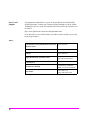
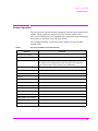
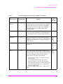
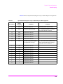
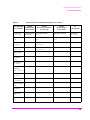
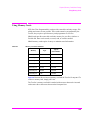
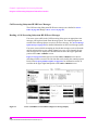
Guideline #1. Avoid using the TX TEST and RX TEST screens.
The RX TEST and TX TEST screens are specifically designed for manual testing of
land mobile FM radios and, when displayed, automatically configure six “priority”
fields in the Test Set for this purpose. The priority fields and their preset values are
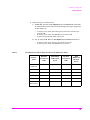
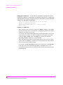
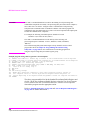
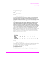
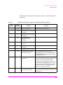
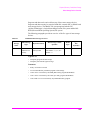
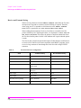
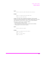
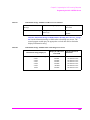
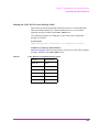
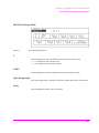
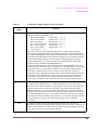
listed in Table 3 on page 37. When the TX TEST screen or the RX TEST screen is
displayed, certain priority fields are hidden and are not settable. The priority fields
which are hidden are listed in Table 3 on page 37.
NOTE:
When the TX TEST screen or the RX TEST screen is displayed, any GPIB commands sent to
the Test Set to change the value of a hidden priority field are ignored. Hidden priority fields
on the TX TEST or RX TEST screens are not settable manually or programmatically.
Displaying either of these screens automatically re-configures the 6 “priority” fields as
follows:
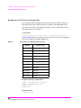
1. When entering the RX TEST screen,
a. the RF Generator’s Amplitude field, the AFGen1 To field and the AF
Analyzer’s measurement field (measurement displayed in upper, right portion
of CRT display) are
•
•
•
set to their preset values upon entering the screen for the first time since
power-up, OR
set to their preset values if the PRESET key is selected, OR
set to the last setting made while in the screen
b. the RF Generator Amplitude field and the AFGen1 To field are
•
•
set to their preset values whenever entering the screen, OR
set to their preset values if the PRESET key is selected
36
S:\agilent\8920\8920b\PRGGUIDE\BOOK\CHAPTERS\usehpib.fb
Chapter 1, Using GPIB
Getting Started
2. When entering the TX TEST screen,
a. The AF Anl In field, the De-Emphasis field, the Detector field and the
AF Analyzer Measurement field (measurement displayed in upper, right portion
of CRT display) are,
•
•
•
set to their preset values upon entering the screen for the first time since
power-up, OR
set to their preset values if the PRESET key is selected, OR
set to the last setting made while in the screen
b. The AF Analyzer AF Anl In, De-Emphasis and Detector fields are,
•
•
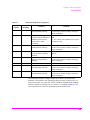
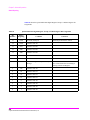
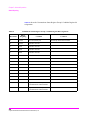
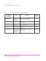
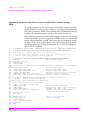
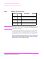
Table 3
set to their preset values whenever entering the screen, OR
set to their preset values if the PRESET key is selected
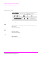
RX TEST Screen and TX TEST Screen Priority Field Preset Values
RX TEST
Screen Preset
Value
Field Hidden
On RX TEST
Screen
TX TEST
Screen Preset
Value
Field
Hidden On
TX TEST
Screen
RF Gen
Amplitude
−80 dBm
No
Off
Yes
AFGen1 To
FM
No
Audio Out
Yes
AF Anl In
Audio In
Yes
FM Demod
No
Detector
RMS
Yes
Pk ± Max
No
De-emphasis
Off
Yes
750 µs
No
AF Analyzer
Measurement
SINAD
No
Audio Freq
No
Priority
Field
37
Chapter 1, Using GPIB
Getting Started
•
Guideline #2. When developing programs to make measurements always follow this
recommended sequence:
1. Bring the Test Set to its preset state using the front-panel PRESET key. This initial
step allows you to start developing the measurement sequence with most fields in a
known state.
2. Make the measurement manually using the front-panel controls of the Test Set.
Record, in sequential order, the screens selected and the settings made within each
screen. The record of the screens selected and settings made in each screen becomes
the measurement procedure.
3. Record the measurement result(s).
In addition to the DISPlay command, the signaling ENCoder and DECoder require
further commands to display the correct fields for each signaling mode. For
example, DISP ENC;:ENC:MODE 'DTMF'.
4. Develop the program using the measurement procedure generated in step 2. Be sure
to start the programmatic measurement sequence by bringing the Test Set to its preset
state using the *RST Common Command. As the measurement procedure requires
changing screens, use the DISPlay command to select the desired screen followed by
the correct commands to set the desired field(s).
NOTE:
When IBASIC programs are running the CRT is dedicated to the IBASIC Controller for
program and graphics display. This means instrument front panels are not displayed on the
CRT when an IBASIC program is running. However, the DISPlay <screen> command causes
all setting and measurement fields in the <screen> to be accessible programmatically.
Attempting to read from a screen that has not been made accessible by the DISPlay command
will cause
HP-IB Error:-420 Query UNTERMINATED, or
HP-IB Error: -113 Undefined header
5. Make sure the desired measurement is in the ON state. This is the preset state for
most measurements. However, if a previous program has set the state to OFF, the
measurement will not be available. Attempting to read from a measurement field
that is not in the ON state will cause HP-IB Error:-420 Query
UNTERMINATED.
6. If the trigger mode has been changed, trigger a reading.
NOTE:
Triggering is set to FULL SETTling and REPetitive RETRiggering after receipt of the *RST
Common Command. These settings cause the Test Set to trigger itself and a separate trigger
command is not necessary.
38
S:\agilent\8920\8920b\PRGGUIDE\BOOK\CHAPTERS\usehpib.fb
Chapter 1, Using GPIB
Getting Started
7. Send the MEASure query command to initiate a reading. This will place the
measured value into the Test Set’s Output Queue.
NOTE:
When making AF Analyzer SINAD, Distortion, Signal to Noise Ratio, AF Frequency, DC
Level, or Current measurements, the measurement type must first be selected using the SELect
command. For example, MEAS:AFR:SEL'SINAD' followed by MEAS:AFR:SINAD?
8. Use the ENTER statement to transfer the measured value to a variable within the
context of the program.
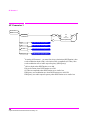
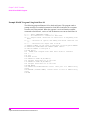
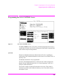
The following example program illustrates how to make settings and then take a
reading from the Test Set. This setup takes a reading from the spectrum analyzer
marker after tuning it to the RF generator’s output frequency.
Example
10 Addr=714
20 OUTPUT Addr;"*RST" !Preset to known state
30 OUTPUT Addr;"TRIG:MODE:RETR SING" !Sets single trigger
40 OUTPUT Addr;"DISP RFG" !Selects the RF Gen screen
50 OUTPUT Addr;"AFG1:FM:STAT OFF" !Turns FM OFF
60 OUTPUT Addr;"RFG:AMPL -66 DBM" !Sets RF Gen ampl to -66 dBm
70 OUTPUT Addr;"RFG:FREQ 500 MHZ" !Sets RF Gen freq to 500 MHz
80 OUTPUT Addr;"RFG:AMPL:STAT ON" !Turns RF Gen output ON
90 OUTPUT Addr;"DISP SAN"!Selects Spectrum Analyzer’s screen
100 OUTPUT Addr;"SAN:CRF 500 MHZ" !Center Frequency 500 MHz
110 ! -------------------MEASUREMENT SEQUENCE------------------120 OUTPUT Addr;"TRIG" !Triggers reading
130 OUTPUT Addr;"MEAS:SAN:MARK:LEV?" !Query of Spectrum
140 !Analyzer’s marker level
150 ENTER Addr;Lvl !Places measured value in variable Lvl
160 DISP Lvl!Displays value of Lvl
170 END
The RF Generator’s output port and the Spectrum Analyzer’s input port are preset
to the RF IN/OUT port. This allows the Spectrum Analyzer to measure the RF
Generator with no external connections. The Spectrum Analyzer marker is always
tuned to the center frequency of the Spectrum Analyzer after preset. With the RF
Generator’s output port and Spectrum Analyzer input port both directed to the RF
IN/OUT port, the two will internally couple with 46 dB of gain, giving a measured
value of approximately -20 dBm. While not a normal mode of operation this setup
is convenient for demonstration since no external cables are required. This also
illustrates the value of starting from the preset state since fewer programming
commands are required.
39
Chapter 1, Using GPIB
Getting Started
•
Guideline #3. Avoid program hangs.
If the program stops or “hangs up” when trying to ENTER a measured value, it is most
likely that the desired measurement field is not available. There are several reasons
that can happen:
1. The screen where the measurement field is located has not been DISPlayed before
querying the measurement field.
2. The measurement is not turned ON.
3. The squelch control is set too high. If a measurement is turned ON but is not
available due to the Squelch setting, the measurement field contains four dashes
(- - - -). This is a valid state. The Test Set is waiting for a signal of sufficient strength
to unsquelch the receiver before making a measurement. If a measurement field
which is squelched is queried the Test Set will wait indefinitely for the receiver to
unsquelch and return a measured value.
4. The RF Analyzer’s Input Port is set to ANT (antenna) while trying to read TX
power. TX power is not measurable with the Input Port set to ANT. The TX power
measurement field will display four dashes (- - - -) indicating the measurement is
unavailable.
5. The input signal to the Test Set is very unstable causing the Test Set to continuously
autorange. This condition will be apparent if an attempt is made to make the
measurement manually.
6. Trigger mode has been set to single trigger (TRIG:MODE:RETRig SINGle) and a
new measurement cycle has not been triggered before attempting to read the
measured value.
7. The program is attempting to make an FM deviation or AM depth measurement
while in the RX TEST screen. FM or AM measurements are not available in the RX
TEST screen. FM or AM measurements are made from the AF Analyzer screen by
setting the AF Anl In field to FM or AM Demod.
40
S:\agilent\8920\8920b\PRGGUIDE\BOOK\CHAPTERS\usehpib.fb
Chapter 1, Using GPIB
Getting Started
•
Guideline #4. Use single quotes and spaces properly.
The syntax diagrams in Chapter 4, “GPIB Commands,” show where single quotes
are needed and where spaces are needed.
Example
OUTPUT 714;"DISP<space>AFAN"
OUTPUT 714;"AFAN:DEMP<space>’Off’"
Improper use of single quotes and spaces will cause,
HP-IB Error:-103 Invalid Separator
•
Guideline #5. Ensure that settable fields are active by using the STATe ON command.
When making settings to fields that can be turned OFF with the STATe ON/OFF
command (refer to the Chapter 4, “GPIB Commands,”), make sure the STATe is ON
if the program uses that field. Note that if the STATe is OFF, just setting a numeric
value in the field will not change the STATe to ON. This is different than front-panel
operation whereby the process of selecting the field and entering a value automatically
sets the STATe to ON. Programmatically, fields must be explicitly set to the ON state if
they are in the OFF state.
For example, the following command line would set a new AMPS ENCoder SAT tone
deviation and then turn on the SAT tone (note the use of the ; to back up one level in
the command hierarchy so that more than one command can be executed in a single
line):
Example
OUTPUT 714;"ENC:AMPS:SAT:FM 2.1 KHZ;FM:STAT ON"
To just turn on the SAT tone without changing the current setting the following
commands would be used:
OUTPUT 714;"ENC:AMPS:SAT:FM:STAT ON"
41
Chapter 1, Using GPIB
Getting Started
•
Guideline #6. Numeric values are returned in GPIB Units or Attribute Units only.
When querying measurements or settings through GPIB, the Test Set always returns
numeric values in GPIB Units or Attribute Units, regardless of the current Display
Units setting. GPIB Units, Attribute Units and Display Units determine the units-ofmeasure used for a measurement or setting, for example, Hz, Volts, Watts, Amperes,
Ohms. Refer to “Specifying Units-of-Measure for Settings and Measurement
Results” on page 75 for further information.
For example, if the Test Set’s front panel is displaying TX Frequency as 835.02 MHz,
and the field is queried through GPIB, the value returned will be 835020000 since the
GPIB Units for frequency are Hz. Note that changing Display Units will not change
GPIB Units or Attribute Units. Note also that setting the value of a numeric field
through GPIB can be done using a variety of units-of-measure. The GPIB Units or
Attribute Units for a queried value can always be determined using the :UNITs?
command or :AUNits? command respectively (refer to “Number Measurement
Syntax” on page 177 or “Multiple Number Measurement Syntax” on page 179,
for command syntax).
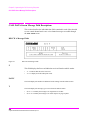
Control Annunciators
The letters and symbols at the top right corner of the display indicate these
conditions:
•
R indicates the Test Set is in remote mode. The Test Set can be put into the remote mode
by an external controller or by an IBASIC program running on the built-in IBASIC
controller.
•
L indicates that the Test Set has been addressed to Listen.
•
T indicates that the Test Set has been addressed to Talk.
•
S indicates that the Test Set has sent the Require Service message by setting the Service
Request (SRQ) bus line true. (See “Status Reporting” on page 239.)
•
C indicates that the Test Set is currently the Active Controller on the bus.
•
* indicates that an IBASIC program is running.
•
? indicates that an IBASIC program is waiting for a user response.
•
- indicates that an IBASIC program is paused.
42
S:\agilent\8920\8920b\PRGGUIDE\BOOK\CHAPTERS\usehpib.fb
Chapter 1, Using GPIB
Getting Started
Preparing the Test Set For GPIB Use
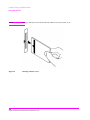
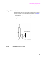
1. If other GPIB devices are in the system, attach a GPIB cable from the Test Set’s rearpanel GPIB connector to any one of the other devices in the test system.
2. Access the I/O CONFIGURE screen and perform the following steps:
a. Set the Test Set’s GPIB address using the HP-IB Adrs field.
b. Set the Test Set’s GPIB Controller capability using the Mode field.
NOTE:
•
Talk&Listen configures the Test Set to not be the System Controller. The Test Set
has Active Controller capability (take control/pass control) in this mode. Use this
setting if the Test Set will be controlled through GPIB from an external controller.
•
Control configures the Test Set to be the System Controller. Use this setting if the
Test Set will be the only controller on the GPIB. Selecting the Control mode
automatically makes the Test Set the Active Controller.
Only one System Controller can be configured in a GPIB system. Refer to “Passing Control”
on page 313 for further information.
3. If a GPIB printer is or will be connected to the Test Set’s rear panel GPIB connector
then,
a. access the PRINT CONFIGURE screen.
b. select one of the supported GPIB printer models using the Model field.
c. set the Printer Port field to HP-IB.
d. set the printer address using the Printer Address field.
43
Chapter 1, Using GPIB
Getting Started
Using the GPIB with the Test Set’s built-in IBASIC Controller
The Test Set has two GPIB interfaces, an internal-only GPIB at select code 8 and
an external GPIB at select code 71. The GPIB at select code 8 is only available to
the built-in IBASIC Controller and is used exclusively for communication
between the IBASIC Controller and the Test Set. The GPIB at select code 71
serves three purposes:
1. It allows the Test Set to be controlled by an external controller
2. It allows the Test Set to print to an external GPIB printer
3. It allows the built-in IBASIC Controller to control external GPIB devices
IBASIC programs running on the Test Set’s IBASIC Controller must use the
internal-only GPIB at select code 8 to control the Test Set. IBASIC programs
would use the external GPIB at select code 71 to control GPIB devices connected
to the rear panel GPIB connector.
NOTE:
Refer to “Overview of the Test Set” on page 26 for a detailed explanation of the Test Set’s
architecture.
When using a BASIC language Workstation with an GPIB interface at select code
7 to control the Test Set, GPIB commands would look like this:
Example
! This
OUTPUT
! This
OUTPUT
command is sent to the Test Set at address 14.
714;"*RST"
command is sent to another instrument whose address is 19.
719;"*RST"
When executing the same commands on the Test Set’s IBASIC Controller, the
commands would look like this:
Example
OUTPUT 814;"*RST"
! Command sent to internal-only GPIB at select code 8,
! Test Set’s address does not change
OUTPUT 719;"*RST"
! Command sent to external GPIB at select code 7,
! other instrument’s address does not change.
1.
Optional Connector on the Test Set.
44
S:\agilent\8920\8920b\PRGGUIDE\BOOK\CHAPTERS\usehpib.fb
Chapter 1, Using GPIB
Getting Started
Basic Programming Examples
The following simple examples illustrate the basic approach to controlling the
Test Set through the GPIB. The punctuation and command syntax used for these
examples is given in Chapter 4, “GPIB Commands.”.
The bus address 714 used in the following BASIC language examples assumes a
GPIB interface at select code 7, and a Test Set GPIB address of 14. All examples
assume an external controller is being used.
To Change a Field’s Setting over GPIB
1. Use the DISPlay command to access the screen containing the field whose setting is to
be changed.
2. Make the desired setting using the proper command syntax (refer to Chapter 4, “GPIB
Commands,” for proper syntax).
The following example makes several instrument setting changes:
Example
OUTPUT
OUTPUT
OUTPUT
OUTPUT
OUTPUT
714;"DISP RFG" !Display the RF Generator screen.
714;"RFG:FREQ 850 MHZ" !Set the RF Gen Freq to 850 MHz.
714;"RFG:OUTP ’DUPL’"!Set the Output Port to Duplex.
714;"DISP AFAN"!Display the AF Analyzer screen.
714;"AFAN:INP ’FM DEMOD’"!Set the AF Anl In to FM Demod.
To Read a Field’s Setting over GPIB37
1. Use the DISPlay command to access the screen containing the field whose setting is to
be read.
2. Use the Query form of the syntax for that field to place the setting value into the Test
Set’s output buffer.
3. Enter the value into the correct variable type within the program context (refer to
Chapter 4, “GPIB Commands,”, for proper variable type).
45
Chapter 1, Using GPIB
Getting Started
The following example reads several fields.
Example
OUTPUT 714;"DISP AFAN"!Display the AF Analyzer screen.
OUTPUT 714;"AFAN:INP?"!Query the AF Anl In field
ENTER 714;Af_input$ !Enter returned value into a string ariable.
OUTPUT 714;"DISP RFG"!Display the RF Generator screen
OUTPUT 714;"RFG:FREQ?"!Query the RF Gen Frequency field.
ENTER 714;Freq !Enter the returned value into a numeric variable
NOTE:
When querying measurements or settings through GPIB, the Test Set always returns numeric
values in GPIB Units or Attribute Units, regardless of the current Display Units setting. Refer
to “GPIB Units (UNITs)” on page 78 and “Attribute Units (AUNits)” on page 81 for
further information.
To Make a Simple Measurement
The basic method for making a measurement is very similar to the method used to
read a field setting.
1. Use the DISPlay command to access the screen containing the desired measurement.
2. Use the MEASure form of the syntax for that measurement to place the measured value
into the Test Set’s output buffer.
3. Enter the value into the correct variable type within the program context (refer to
Chapter 4, “GPIB Commands,” for proper variable type).
The following example measures the power of an RF signal.
Example
!Display the RF Analyzer screen.
OUTPUT 714;"DISP RFAN"
!Measure the RF power and place result in output buffer.
OUTPUT 714;"MEAS:RFR:POW?"
!Enter the measured value into a numeric variable.
ENTER 714;Tx_power
The above example is very simple and is designed to demonstrate the fundamental
procedure for obtaining a measurement result. Many other factors must be
considered when designing a measurement procedure, such as instrument settings,
signal routing, settling time, filtering, triggering and measurement speed.
46
S:\agilent\8920\8920b\PRGGUIDE\BOOK\CHAPTERS\usehpib.fb
Chapter 1, Using GPIB
Remote Operation
Remote Operation
The Test Set can be operated remotely through the General Purpose Interface Bus
(GPIB). Except as otherwise noted, the Test Set complies with the IEEE
488.1-1987 and IEEE 488.2-1987 Standards. Bus compatibility, programming and
data formats are described in the following sections.
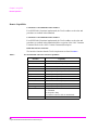
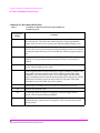
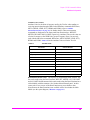
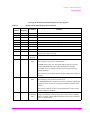
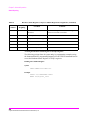
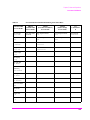
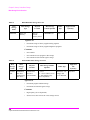
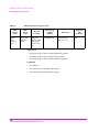
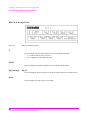
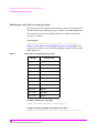
All front-panel functions, except those listed in Table 4, are programmable
through GPIB.
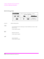
Table 4
Non-Programmable Front Panel Functions
Function
Comment
ON/OFF Power Switch
Volume Control Knob
Squelch Control Knob
The position of the Squelch Control knob cannot be programmed. However squelch can be programmed to either the Open or Fixed position.
Refer to the Test Set’s User’s Guide for more information.
Cursor Control Knob
SHIFT Key
CANCEL Key
YES Key
NO Key
ENTER Key
Backspace (left-arrow) Key
PREV Key
HOLD ( SHIFT, PREV Keys)
PRINT ( SHIFT, TESTS Keys)
ADRS ( SHIFT, LOCAL Keys)
ASSIGN ( SHIFT, k4 Keys)
RELEASE ( SHIFT, k5 Keys)
47
Chapter 1, Using GPIB
Remote Operation
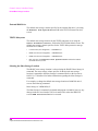
Remote Capabilities
Conformance to the IEEE 488.1-1987 Standard
For all IEEE 488.1 functions implemented, the Test Set adheres to the rules and
procedures as outlined in that Standard.
Conformance to the IEEE 488.2-1987 Standard
For all IEEE 488.2 functions implemented, the Test Set adheres to the rules and
procedures as outlined in that Standard with the exception of the *OPC Common
Command. Refer to the *OPC Common Command description.
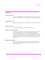
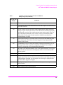
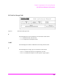
IEEE 488.1 Interface Functions
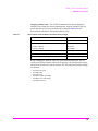
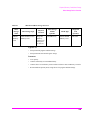
The interface functions that the Test Set implements are listed in Table 5.
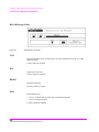
Table 5
Test Set IEEE 488.1 Interface Function Capabilities
Function
Capability
Talker
T6: No Talk Only Mode
Extended Talker
T0: No Extended Talker Capability
Listener
L4: No Listen Only Mode
Extended Listener
LE0: No Extended Listener Capability
Source Handshake
SH1: Complete Capability
Acceptor Handshake
AH1: Complete Capability
Remote/Local
RL1: Complete Capability
Service Request
SR1: Complete Capability
Parallel Poll
PP0: No Parallel Poll Capability
Device Clear
DC1: Complete Capability
Device Trigger
DT1: Complete Capability
Controller
C1: System Controller
C3: Send REN
C4: Respond to SRQ
C11:No Pass Control to Self, No Parallel Poll
Drivers
E2: Tri-State Drivers
48
S:\agilent\8920\8920b\PRGGUIDE\BOOK\CHAPTERS\usehpib.fb
Chapter 1, Using GPIB
Addressing
Addressing
Factory Set Address
The Test Set’s GPIB address is set to decimal 14 at the factory. The address can be
changed by following the instructions in “Setting the Test Set’s Bus Address” on page
49.
Extended Addressing
Extended addressing (secondary command) capability is not implemented in the Test
Set.
Multiple Addressing
Multiple addressing capability is not implemented in the Test Set.
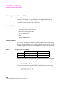
Setting the Test Set’s Bus Address
The Test Set’s GPIB bus address is set using the HP-IB Adrs field which is located
on the I/O CONFIGURE screen. To set the GPIB bus address; select the I/O
CONFIGURE screen and position the cursor next to the HP-IB Adrs field. The
address can be set from decimal 0 to 30 using the numeric DATA keys, or by pushing
and then rotating the Cursor Control knob. There are no DIP switches for setting the
GPIB bus address in the Test Set. The new setting is retained when the Test Set is
turned off.
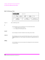
Displaying the Bus Address
The Test Set’s GPIB bus address can be displayed by pressing and releasing the
SHIFT key, then the LOCAL key. The address is displayed in the upper left-hand
corner of the display screen.
49
Chapter 1, Using GPIB
IEEE 488.1 Remote Interface Message Capabilities
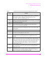
IEEE 488.1 Remote Interface Message Capabilities
The remote interface message capabilities of the Test Set and the associated IEEE
488.1 messages and control lines are listed in Table 6.
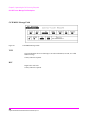
Table 6
Message Type
Test Set IEEE 488.1 Interface Message Capability
IEEE
488.1
Message
Implemented
Response
Data
Yes
All front-panel functions, except those listed in Table 4
on page 47, are programmable. The Test Set can send status byte, message and setting information. All measurement results (except dashed “- - - -” displays) and error
messages are available through the bus.
DAB
END
MTA
MLA
OTA
Remote
Yes
Remote programming mode is entered when the Remote
Enable (REN) bus control line is true and the Test Set is
addressed to listen. The R annunciator will appear in the
upper-right corner of the display screen when the Test Set
is in remote mode. All front-panel keys are disabled
(except for the LOCAL key, POWER switch, Volume control and Squelch control knobs). When the Test Set enters
remote mode the output signals and internal settings
remain unchanged, except that triggering is reset to the
state it was last set to in remote mode (Refer to “Triggering Measurements” on page 224).
REN
MLA
Local
Yes
The Test Set returns to local mode (full front-panel control) when either the Go To Local (GTL) bus command is
received, the front-panel LOCAL key is pressed or the
REN line goes false. When the Test Set returns to local
mode the output signals and internal settings remain
unchanged, except that triggering is reset to
TRIG:MODE:SETT FULL;RETR REP. The LOCAL key
will not function if the Test Set is in the local lockout
mode.
GTL
MLA
Local Lockout
Yes
Local Lockout disables all front-panel keys including the
LOCAL key. Only the System Controller or the POWER
switch can return the Test Set to local mode (front-panel
control).
LLO
50
S:\agilent\8920\8920b\PRGGUIDE\BOOK\CHAPTERS\usehpib.fb
Chapter 1, Using GPIB
IEEE 488.1 Remote Interface Message Capabilities
Table 6
Message Type
Test Set IEEE 488.1 Interface Message Capability (Continued)
IEEE
488.1
Message
Implemented
Response
Clear Lockout/
Set Local
Yes
The Test Set returns to local mode (front-panel control)
and local lockout is cleared when the REN bus control line
goes false. When the Test Set returns to local mode the
output signals and internal settings remain unchanged,
except that triggering is set to TRIG:MODE:SETT
FULL;RETR REP.
REN
Service Request
Yes
The Test Set sets the Service Request (SRQ) bus line true
if any of the enabled conditions in the Status Byte Register, as defined by the Service Request Enable Register, are
true.
SRQ
Status Byte
Yes
The Test Set responds to a Serial Poll Enable (SPE) bus
command by sending an 8-bit status byte when addressed
to talk. Bit 6 will be true, logic 1, if the Test Set has sent
the SRQ message
SPE
SPD
STB
MTA
Status Bit
No
The Test Set does not have the capability to respond to a
Parallel Poll.
PPE
PPD
PPU
PPC
IDY
Clear
Yes
This message clears the Input Buffer and Output Queue,
clears any commands in process, puts the Test Set into the
Operation Complete idle state and prepares the Test Set to
receive new commands. The Device Clear (DCL) or
Selected Device Clear (SDC) bus commands
DCL
SDC
MLA
•
do not change any settings or stored data (except as
noted previously)
• do not interrupt front panel I/O or any Test Set
operation in progress (except as noted previously)
• do not change the contents of the Status Byte Register
(other than clearing the MAV bit as a consequence of
clearing the Output Queue).
The Test Set responds equally to DCL or SDC bus commands.
51
Chapter 1, Using GPIB
IEEE 488.1 Remote Interface Message Capabilities
Table 6
Message Type
Test Set IEEE 488.1 Interface Message Capability (Continued)
IEEE
488.1
Message
Implemented
Response
Trigger
Yes
If in remote programming mode and addressed to listen,
the Test Set makes a triggered measurement following the
trigger conditions currently in effect in the instrument.
The Test Set responds equally to the Group Execute Trigger (GET) bus command or the *TRG Common Command.
GET
MLA
Take Control
Yes
The Test Set begins to act as the Active Controller on the
bus.
TCT
MTA
Abort
Yes
The Test Set stops talking and listening
IFC
52
S:\agilent\8920\8920b\PRGGUIDE\BOOK\CHAPTERS\usehpib.fb
Chapter 1, Using GPIB
Remote/Local Modes
Remote/Local Modes
Remote Mode
In Remote mode all front-panel keys are disabled (except for the LOCAL key,
POWER switch, Volume control and Squelch control). The LOCAL key is only
disabled by the Local Lockout bus command. When in Remote mode and
addressed to Listen the Test Set responds to the Data, Remote, Local, Clear
(SDC), and Trigger messages. When the Test Set is in Remote mode, the R
annunciator will be displayed in the upper right corner of the display screen and
triggering is set to the state it was last set to in Remote mode (if no previous
setting, the default is FULL SETTling and REPetitive RETRiggering). When the
Test Set is being addressed to Listen or Talk the L or T annunciators will be
displayed in the upper-right corner of the display screen.
Local Mode
In Local mode the Test Set’s front-panel controls are fully operational. The Test
Set uses FULL SETTling and REPetitive RETRiggering in Local mode. When the
Test Set is being addressed to Listen or Talk the L or T annunciators will be
displayed in the upper-right corner of the display screen.
Remote or Local Mode
When addressed to Talk in Remote or Local mode, the Test Set can issue the Data
and Status Byte messages and respond to the Take Control message. In addition
the Test Set can issue the Service Request Message (SRQ). Regardless of whether
it is addressed to talk or listen, the Test Set will respond to the Clear (DCL), Local
Lockout, Clear Lockout/Set Local, and Abort messages.
53
Chapter 1, Using GPIB
Remote/Local Modes
Local To Remote Transitions
The Test Set switches from Local to Remote mode upon receipt of the Remote
message (REN bus line true and Test Set is addressed to listen). No instrument
settings are changed by the transition from Local to Remote mode, but triggering
is set to the state it was last set to in Remote mode (if no previous setting, the
default is FULL SETTling and REPetitive RETRiggering). The R annunciator in
the upper-right corner of the display is turned on.
When the Test Set makes a transition from local to remote mode, all currently
active measurements are flagged as invalid causing any currently available
measurement results to become unavailable. If the GPIB trigger mode is
:RETR REP then a new measurement cycle is started and measurement results
will be available for all active measurements when valid results have been
obtained. If the GPIB trigger mode is :RETR SING then a measurement cycle
must be started by issuing a trigger event. Refer to “Triggering Measurements” on
page 224 for more information.
Remote To Local Transitions
The Test Set switches from Remote to Local mode upon receipt of the Local
message (Go To Local bus message is sent and Test Set is addressed to listen) or
receipt of the Clear Lockout/Set Local message (REN bus line false). No
instrument settings are changed by the transition from Remote to Local mode, but
triggering is reset to FULL SETTling and REPetitive RETRiggering. The R
annunciator in the upper right corner of the display is turned off.
If it is not in Local Lockout mode the Test Set switches from Remote to Local
mode whenever the front-panel LOCAL key is pressed.
If the Test Set was in Local Lockout mode when the Local message was received,
front-panel control is returned, but Local Lockout mode is not cleared. Unless the
Test Set receives the Clear Lockout/Set Local message, the Test Set will still be in
Local Lockout mode the next time it goes to the Remote mode.
54
S:\agilent\8920\8920b\PRGGUIDE\BOOK\CHAPTERS\usehpib.fb
Chapter 1, Using GPIB
Remote/Local Modes
Local Lockout
The Local Lockout mode disables the front-panel LOCAL key and allows return
to Local mode only by commands from the System Controller (Clear Lockout/Set
Local message).
When a data transmission to the Test Set is interrupted, which can happen if the
LOCAL key is pressed, the data being transmitted may be lost. This can leave the
Test Set in an unknown state. The Local Lockout mode prevents loss of data or
system control due to someone unintentionally pressing front-panel keys.
NOTE:
Return to Local mode can also be accomplished by setting the POWER switch to OFF and
back to ON. However, returning to Local mode in this way has the following disadvantages:
1. It defeats the purpose of the Local Lockout mode in that the Active Controller will lose
control of the test set.
2. Instrument configuration is reset to the power up condition thereby losing the
instrument configuration set by the Active Controller.
Clear Lockout/Set Local
The Test Set returns to Local mode when it receives the Clear Lockout/Set Local
message. No instrument settings are changed by the transition from Remote mode
with Local Lockout to Local mode but triggering is reset to FULL SETTling and
REPetitive RETRiggering.
55
Chapter 1, Using GPIB
Remote/Local Modes
56
S:\agilent\8920\8920b\PRGGUIDE\BOOK\CHAPTERS\usehpib.fb
2
Methods For Reading Measurement
Results
57
Chapter 2, Methods For Reading Measurement Results
Background
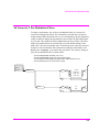
Background
One of the most common remote user interface operations performed on an
Test Set is to query and read a measurement result. Generally, this operation is
accomplished by sending the query command to the Test Set, followed
immediately by a request to read the requested measurement result. Using
Hewlett-Packard Rocky Mountain BASIC (RMB) language, this operation would
be written using the OUTPUT and ENTER command as follows:
OUTPUT 714;"MEAS:RFR:POW?"
ENTER 714;Power
Using this programming structure, the control program will stay on the ENTER
statement until it is satisfied - that is - until the Test Set has returned the requested
measurement result. This structure works correctly as long as the Test Set returns
a valid measurement result. If, for some reason, the Test Set does not return a
measurement result, the control program becomes “hung” on the ENTER
statement and program execution effectively stops.
In order to prevent the control program from becoming “hung” programmers
usually enclose the operation with some form of timeout function. The form of the
timeout will of course depend upon the programming language being used. The
purpose of the timeout is to specify a fixed amount of time that the control
program will wait for the Test Set to return the requested result. After this time has
expired the control program will abandon the ENTER statement and try to take
some corrective action to regain control of the Test Set.
If the control program does not send the proper commands in the proper sequence
when trying to regain control of the Test Set, unexpected operation will result.
When this condition is encountered, power must be cycled on the Test Set to
regain control.
58
S:\agilent\8920\8920b\PRGGUIDE\BOOK\CHAPTERS\measrslt.fb
Chapter 2, Methods For Reading Measurement Results
Background
This situation can be avoided entirely by:
1. sending a Selected Device Clear (SDC) interface message to put the Test Set’s GPIB
subsystem into a known state.
2. sending a command to terminate the requested measurement cycle.
These commands issued in this order will allow the control program to regain
control of the Test Set. Any other sequence of commands will result in unexpected
operation.
The following programs demonstrate a recommended technique for querying and
entering data from the Test Set. This technique will prevent the Test Set from
getting into a ‘hung’ state such that power must be cycled on the Test Set to regain
manual or programmatic control.
There are a variety of programming constructs which can be used to implement
this technique. In the programming examples presented, a function call is
implemented which returns a numeric measurement result. The function call has
two pass parameters; the query command (passed as a quoted string) and a timeout value (passed as a integer number).
The time-out value represents how long you want to wait, in seconds, for the Test
Set to return a valid measurement result. If a valid measurement result is not
returned by the Test Set within the time-out value, the function returns a very large
number. The calling program can check the value and take appropriate action.
The program examples are written so as to be self-explanatory. In practice, the
length of: variable names, line labels, function names, etc., will be
implementation dependent.
59
Chapter 2, Methods For Reading Measurement Results
HP® BASIC ‘ON TIMEOUT’ Example Program
HP® BASIC ‘ON TIMEOUT’ Example Program
The following example program demonstrates a recommended technique which
can be utilized in situations where a measurement result timeout value of 32.767
seconds or less is adequate. In the Agilent RMB language, the timeout parameter
for the ON TIMEOUT command has a maximum value of 32.767 seconds. If a
timeout value of greater than 32.767 seconds is required refer to the HP®
BASIC ‘MAV’ Bit Example Program.
The measurement result timeout value is defined to mean the amount of time the
control program is willing to wait for the Test Set to return a valid measurement
result to the control program.
Lines 10 thru 230 in this example set up a measurement situation to demonstrate
the use of the recommended technique. The recommended technique is exampled
in the Measure Function.
NOTE:
Lines 50 and 60 should be included in the beginning of all control program. These lines are
required to ensure that the Test Set is properly reset. This covers the case where the program
was previously run and was stopped with the Test Set in an error condition.
60
S:\agilent\8920\8920b\PRGGUIDE\BOOK\CHAPTERS\measrslt.fb
Chapter 2, Methods For Reading Measurement Results
HP® BASIC ‘ON TIMEOUT’ Example Program
10
20
30
40
50
60
70
80
90
100
110
120
130
140
150
160
170
180
190
200
210
220
230
240
250
260
270
280
290
300
310
320
330
340
350
360
370
380
390
400
410
420
430
440
450
460
COM /Io_names/ INTEGER Inst_addr,Bus_addr
CLEAR SCREEN
Inst_addr=714
Bus_addr=7
CLEAR Inst_addr
OUTPUT Inst_addr;"TRIG:ABORT"
OUTPUT Inst_addr;"*RST"
OUTPUT Inst_addr;"DISP RFAN"
!
! Execute a call to the Measure function with a request to measure RF
! power. The time out value is specified as 10 seconds. The value
! returned by the function is assigned to the variable Measure_result.
!
Measure_result=FNMeasure("MEAS:RFR:POW?",10)
!
! Check the result of the function call.
!
IF Measure_result=9.E+99 THEN
PRINT "Measurement failed."
ELSE
PRINT "Power = ";Measure_result
END IF
END
!***********************************************************
! Recommended Technique:
!***********************************************************
DEF FNMeasure(Query_command$,Time_out_value)
COM /Io_names/ INTEGER Inst_addr,Bus_addr
DISABLE
ON TIMEOUT Bus_addr,Time_out_value RECOVER Timed_out
OUTPUT Inst_addr;"TRIG:MODE:RETR SING;:TRIG:IMM"
OUTPUT Inst_addr;Query_command$
ENTER Inst_addr;Result
OUTPUT Inst_addr;"TRIG:MODE:RETR REP"
ENABLE
RETURN Result
Timed_out:!
ON TIMEOUT Bus_addr,Time_out_value GOTO Cannot_recover
CLEAR Inst_addr
OUTPUT Inst_addr;"TRIG:ABORT;MODE:RETR REP"
ENABLE
RETURN 9.E+99
Cannot_recover:!
DISP "Cannot regain control of Test Set."
STOP
FNEND
61
Chapter 2, Methods For Reading Measurement Results
HP® BASIC ‘ON TIMEOUT’ Example Program
Comments for Recommended Routine
Table 7
Comments for Measure Function from ON TIMEOUT
Example Program
Program Line
Number
Comments
50
Send a Selected Device Clear (SDC) to the Test Set to put the GPIB subsystem
into a known state. This allows the control program to regain programmatic
control of the Test Set if it is in an error state when the program begins to run.
60
Command the Test Set to abort the currently executing measurement cycle. This
will force the Test Set to stop waiting for any measurement results to be available
from measurements which may be in an invalid state when the program begins to
run.
290
Turn event initiated branches off (except ON END, ON ERROR and ON
TIMEOUT) to ensure that the Measure function will not be exited until it is
finished.
300
Set up a timeout for any I/O activity on the GPIB. This will allow the function to
recover if the bus hangs for any reason.
310
Set the triggering mode to single followed by a trigger immediate command. This
ensures that a new measurement cycle will be started when the TRIG:IMM
command is sent. This sequence, that is: set to single trigger and then send a
trigger command, guarantees that the measurement result returned to the ENTER
statement will accurately reflect the state of the DUT when the TRIG:IMM
command was sent. The ’IMM’ keyword is optional.
320
Send the query command passed to the Measure function to the Test Set.
330
Read the measurement result.
340
Set the trigger mode to repetitive retriggering. Setting the trigger mode to
repetitive will be implementation dependent.
350
Re-enable event initiated branching. If any event initiated branches were logged
while the Measure function was executing they will be executed when system
priority permits.
62
S:\agilent\8920\8920b\PRGGUIDE\BOOK\CHAPTERS\measrslt.fb
Chapter 2, Methods For Reading Measurement Results
HP® BASIC ‘ON TIMEOUT’ Example Program
Table 7
Comments for Measure Function from ON TIMEOUT
Example Program (Continued)
Program Line
Number
Comments
360
Exit the Measure function and return the result value.
370
The following lines of code handle the case where the request for a measurement
result has timed out.
380
Set up a timeout for any I/O activity on the GPIB while the control program is
trying to regain control of the Test Set. This will allow the function to gracefully
stop program execution if the control program cannot regain control of the Test
Set. This timeout should only occur if there is some type of hardware failure,
either in the Test Set or the external controller, which prevents them from
communicating via GPIB.
390
Send a Selected Device Clear (SDC) to the Test Set to put the GPIB subsystem
into a known state. This allows the control program to regain programmatic
control of the Test Set.
400
Command the Test Set to abort the currently executing measurement cycle. Set
the trigger mode back to repetitive retriggering. Setting the Test Set back to
repetitive retriggering will be implementation dependent.
410
Re-enable event initiated branching. If any event initiated branches were logged
while the Measure function was executing they will be executed when system
priority permits.
420
Exit the Measure function and return a result value of 9.E+99.
430
The following lines of code handle the case where the control program cannot
regain control of the Test Set. The actions taken in this section of the code will be
implementation dependent. For the example case a message is displayed to the
operator and the program is stopped.
440
Display a message to the operator that the control program cannot regain control
of the Test Set.
450
Stop execution of the control program.
63
Chapter 2, Methods For Reading Measurement Results
HP® BASIC ‘MAV’ Example Program
HP® BASIC ‘MAV’ Example Program
The following Agilent RMB example program demonstrates a technique which
can be used in situations where a 32.767 measurement result timeout value is not
adequate.
Measurement result timeout value is defined to mean the amount of time the
control program is willing to wait for the Test Set to return a valid measurement
result to the control program.
The technique uses the MAV (Message Available) bit in the Test Set’s GPIB
Status Byte to determine when there is data in the Output Queue. A polling loop is
used to query the Status byte. The timeout duration for returning the measurement
result is handled by the polling loop. An GPIB interface activity timeout is also set
up to handle time-outs resulting from problems with the GPIB interface.
Lines 10 thru 230 in this example set up a measurement situation to demonstrate
the use of the recommended technique. The recommended technique is exampled
in the Measure Function.
NOTE:
Lines 50 and 60 should be included in the beginning of all control program. These lines are
required to ensure that the Test Set is properly reset. This covers the case where the program
was previously run and was stopped with the Test Set in an error condition.
64
S:\agilent\8920\8920b\PRGGUIDE\BOOK\CHAPTERS\measrslt.fb
Chapter 2, Methods For Reading Measurement Results
HP® BASIC ‘MAV’ Example Program
10
20
30
40
50
60
70
80
90
100
110
120
130
140
150
160
170
180
190
200
210
220
230
240
250
260
270
280
290
300
310
320
330
340
350
360
370
380
390
400
410
420
430
440
450
460
470
480
490
500
510
520
COM /Io_names/ INTEGER Inst_addr,Bus_addr
CLEAR SCREEN
Inst_addr=714
Bus_addr=7
CLEAR Inst_addr
OUTPUT Inst_addr;"TRIG:ABORT"
OUTPUT Inst_addr;"*RST"
OUTPUT Inst_addr;"DISP RFAN"
!
! Execute a call to the Measure function with a request to measure RF
! power. The time out value is specified as 50 seconds. The value
! returned by the function is assigned to the variable Measure_result.
!
Measure_result=FNMeasure("MEAS:RFR:POW?",50)
!
! Check the result of the function call.
!
IF Measure_result=9.E+99 THEN
PRINT "Measurement failed."
ELSE
PRINT "Power = ";Measure_result
END IF
END
!***********************************************************
! Recommended Technique:
!***********************************************************
DEF FNMeasure(Query_command$,Time_out_value)
COM /Io_names/ INTEGER Inst_addr,Bus_addr
DISABLE
ON TIMEOUT Bus_addr,5 GOTO Timed_out
OUTPUT Inst_addr;"TRIG:MODE:RETR SING;:TRIG:IMM"
OUTPUT Inst_addr;Query_command$
Start_time=TIMEDATE
REPEAT
WAIT .1
Status_byte=SPOLL(Inst_addr)
IF BIT(Status_byte,4) THEN
ENTER Inst_addr;Result
OUTPUT Inst_addr;"TRIG:MODE:RETR REP"
ENABLE
RETURN Result
END IF
UNTIL TIMEDATE-Start_time>=Time_out_value
Timed_out:!
ON TIMEOUT Bus_addr,5 GOTO Cannot_recover
CLEAR Inst_addr
OUTPUT Inst_addr;"TRIG:ABORT;MODE:RETR REP"
RETURN 9.E+99
Cannot_recover: !
DISP "Cannot regain control of Test Set."
STOP
FNEND
65
Chapter 2, Methods For Reading Measurement Results
HP® BASIC ‘MAV’ Example Program
Comments for Recommended Routine
Table 8
Comments for Measure Function from MAV Example Program
Program Line
Number
Comments
50
Send a Selected Device Clear (SDC) to the Test Set to put the GPIB subsystem
into a known state. This allows the control program to regain programmatic
control of the Test Set if it is in an error state when the program begins to run.
60
Command the Test Set to abort the currently executing measurement cycle. This
will force the Test Set to stop waiting for any measurement results to be available
from measurements which may be in an invalid state when the program begins to
run.
290
Turn event initiated branches off (except ON END, ON ERROR and ON
TIMEOUT) to ensure that the Measure function will not be exited until it is
finished.
300
Set up a 5 second timeout for any I/O activity on the GPIB. This will allow the
function to recover if the bus hangs for any reason. The length of the timeout will
be implementation dependent.
310
Set the triggering mode to single followed by a trigger immediate command. This
ensures that a new measurement cycle will be started when the TRIG:IMM
command is sent. This sequence, that is: set to single trigger and then send trigger
command, guarantees that the measurement result returned to the ENTER
statement will accurately reflect the state of the DUT when the TRIG:IMM
command was sent. The ’IMM’ keyword is optional.
320
Send the query command passed to the Measure function to the Test Set.
330
Establish a start time against which to compare the measurement result timeout
value passed to the Measure function.
340
Start the status byte polling loop.
350
Allow the Test Set some time (100 milliseconds) to process the measurement.
When polling the Test Set the polling loop must give the Test Set time to process
the requested measurement. Since GPIB command processing has a higher system priority within the Test Set than measurement functions, constantly sending
GPIB commands will result in longer measurement times.
66
S:\agilent\8920\8920b\PRGGUIDE\BOOK\CHAPTERS\measrslt.fb
Chapter 2, Methods For Reading Measurement Results
HP® BASIC ‘MAV’ Example Program
Table 8
Comments for Measure Function from MAV Example Program (Continued)
Program Line
Number
Comments
360
Perform a serial poll to read the Status Byte from the Test Set. A serial poll is
used because the *STB Common Command cannot be processed by the Test Set
while a query is pending. Sending the *STB command will cause an
’HP-IB Error: -410 Query INTERRUPTED’ error.
370
Check bit 4, the Message Available bit (MAV), to see if it is set to ’1’. If it is, then
the requested measurement result is ready.
380
Read the measurement result.
390
Set the trigger mode to repetitive retriggering. Setting the trigger mode to
repetitive will be implementation dependent.
400
Re-enable event initiated branching. If any event initiated branches were logged
while the Measure function was executing they will be executed when system
priority permits.
410
Exit the Measure function and return the result value.
430
Check to see if the measurement result time out value has been equaled or
exceeded. If it has the polling loop will be exited.
440
The following lines of code handle the case where the request for a measurement
result has timed out because the polling loop has completed with no result
available.
450
Set up a timeout for any I/O activity on the GPIB while the control program is
trying to regain control of the Test Set. This will allow the function to gracefully
stop program execution if the control program cannot regain control of the Test
Set. This timeout should only occur if there is some type of hardware failure,
either in the Test Set or the external controller, which prevents them from
communicating via GPIB.
460
Send a Selected Device Clear (SDC) to the Test Set to put the GPIB subsystem
into a known state. This allows the control program to regain programmatic
control of the Test Set.
470
Command the Test Set to abort the currently executing measurement cycle. Set
the trigger mode back to repetitive retriggering. Setting the Test Set back to
repetitive retriggering will be implementation dependent.
67
Chapter 2, Methods For Reading Measurement Results
HP® BASIC ‘MAV’ Example Program
Table 8
Comments for Measure Function from MAV Example Program (Continued)
Program Line
Number
Comments
480
Exit the Measure function and return a result value of 9.E+99.
490
The following lines of code handle the case where the control program cannot
regain control of the Test Set. The actions taken in this section of the code will be
implementation dependent. For the example case a message is displayed to the
operator and the program is stopped.
500
Display a message to the operator that the control program cannot regain control
of the Test Set.
510
Stop execution of the control program.
68
S:\agilent\8920\8920b\PRGGUIDE\BOOK\CHAPTERS\measrslt.fb
3
GPIB1 Command Guidelines
1. GPIB was formerly called HP-IB for Hewlett-Packard instruments. Some labels on
the instrument may still reflect the former HP® name.
69
Chapter 3, GPIB Command Guidelines
Sequential and Overlapped Commands
Sequential and Overlapped Commands
IEEE 488.2 makes the distinction between sequential and overlapped commands.
Sequential commands complete their task before execution of the next command
can begin. Overlapped commands can run concurrently, that is, a command
following an overlapped command may begin execution while the overlapped
command is still in progress. All commands in the Test Set are sequential.
The processing architecture of the Test Set allows it to accept commands through
the GPIB while it is executing commands already parsed into its command buffer.
While this may appear to be overlapped, commands are always executed
sequentially in the order received.
The process of executing a command can be divided into three steps:
1. Command is accepted from GPIB and checked for proper structure and parameters.
2. Commands is sent to instrument hardware.
3. Instrument hardware fully responds after some time, ∆t.
For example, in programming the Test Set’s RF Signal Generator it takes
< 150 ms after receipt of the frequency setting command for the output signal to
be within 100 Hz of the desired frequency. In the Test Set, commands are
considered to have “completed their task” at the end of step 2. In manual
operation all displayed measurement results take into account the instrument
hardware’s response time. When programming measurements through GPIB the
Triggering mode selected will determine whether the instrument’s response time
is accounted for automatically or if the control program must account for it. Refer
to “Triggering Measurements” on page 224 for a discussion of the different Trigger
modes available in the Test Set and their affect on measurement results.
70
S:\agilent\8920\8920b\PRGGUIDE\BOOK\CHAPTERS\guidelin.fb
Chapter 3, GPIB Command Guidelines
Guidelines for Operation
Guidelines for Operation
The following topics discuss rules and guidelines for controlling the Test Set
through GPIB.
Command Names
All command names of more than four characters have an alternate abbreviated
form using only upper case letters and, in some cases, a single numeral. The
commands are not case sensitive. Upper and lower case characters can be used for
all commands.
For example, to set the destination of AF Generator 1 to Audio Out, any of the
following command strings are valid:
AFGENERATOR1:DESTINATION ’AUDIO OUT’
or
afgenerator1:destination ’audio out’
or
afg1:dest ’audio out’
or
AFG1:DEST ’AUDIO OUT’
or
Afg1:Dest ’Audio oUT’
71
Chapter 3, GPIB Command Guidelines
Guidelines for Operation
Command Punctuation
NOTE:
Programming Language Considerations. The punctuation rules for the Test Set’s
GPIB commands conform to the IEEE 488.2 standard. It is possible that some
programming languages used on external controllers may not accept some of the
punctuation requirements. It is therefore necessary that the equivalent form of the correct
punctuation, as defined by the language, be used for GPIB operation. Improper
punctuation will results in HP-IB Error: -102 Syntax Error.
Using Quotes for String Entries
Quotation marks ’ and " are used to select a non-numeric field setting. The value is
entered into the command line as a quoted alphanumeric string.
Quotes are used with all Underlined (toggling) and One-of-many (menu choice)
fields. (See “Changing A Field’s Setting” in chapter 1 of the User’s Guide for field
type descriptions.)
For example, to set the RF Generator’s Output Port field to Dupl (duplex), the
Dupl would be entered into the command string.
RFG:OUTP ’Dupl’
or
RFG:OUTP "Dupl"
Using Spaces
When changing a field’s setting, a space must always precede the setting value in
the command string, regardless of the field type (command<space>value).
RFG:FREQ<space>850MHZ
RFG:ATT<space>’OFF’
72
S:\agilent\8920\8920b\PRGGUIDE\BOOK\CHAPTERS\guidelin.fb
Chapter 3, GPIB Command Guidelines
Guidelines for Operation
Using Colons to Separate Commands
The GPIB command syntax is structured using a control hierarchy that is
analogous to manual operation.
The control hierarchy for making a manual instrument setting using the frontpanel controls is as follows: first the screen is accessed, then the desired field is
selected, then the appropriate setting is made. GPIB commands use the same
hierarchy. The colon (:) is used to separate the different levels of the command
hierarchy.
For example, to set the AF Analyzer input gain to 40 dB, the following command
syntax would be used:
DISP AFAN
AFAN:INP:GAIN ’40 dB’
Using the Semicolon to Output Multiple Commands
Multiple commands can be output from one program line by separating the
commands with a semicolon (;). The semicolon tells the Test Set’s GPIB
command parser to back up one level of hierarchy and accept the next command
at the same level as the previous command.
For example, on one command line, it is possible to
1.
2.
3.
4.
access the AF ANALYZER screen,
set the AF Analyzer’s Input to AM Demod
set Filter 1 to 300 Hz HPF
set Filter 2 to 3kHz LPF
DISP AFAN;AFAN:INP ’AM DEMOD’;FILT1 ’300Hz HPF’;FILT2 ’3kHz LPF’
The semicolon after the “DISP AFAN” command tells the Test Set’s GPIB
command parser that the next command is at the same level in the command
hierarchy as the display command. Similarly, the semicolon after the INP 'AM
DEMOD' command tells the command parser that the next command (FILT1
'300Hz HPF') is at the same command level as the INP 'AM DEMOD' command.
73
Chapter 3, GPIB Command Guidelines
Guidelines for Operation
Using the Semicolon and Colon to Output Multiple Commands
A semicolon followed by a colon (;:) tells the GPIB command parser that the next
command is at the top level of the command hierarchy. This allows commands
from different instruments to be output on one command line. The following
example sets the RF Analyzer’s tune frequency to 850 MHz, and then sets the AF
Analyzer’s input to FM Demod.
RFAN:FREQ 850MHZ;:AFAN:INP ’FM DEMOD’
Using Question Marks to Query Setting or Measurement Fields
The question mark (?) is used to query (read-back) an instrument setting or
measurement value. To generate the query form of a command, place the question
mark immediately after the command. Queried information must be read into the
proper variable type within the program context before it can be displayed,
printed, or used as a numeric value in the program.
Queried information is returned in the same format used to set the value: queried
numeric fields return numeric data; quoted string fields return quoted string
information.
For example, the following BASIC language program statements query the
current setting of the AFGen 1 To field:
!Query the AFGen1 To field
OUTPUT 714;"AFG1:DEST?"
!Enter queried value into a string variable.
ENTER 714;Afg1_to$
74
S:\agilent\8920\8920b\PRGGUIDE\BOOK\CHAPTERS\guidelin.fb
Chapter 3, GPIB Command Guidelines
Guidelines for Operation
Specifying Units-of-Measure for Settings and Measurement Results
Numeric settings and measurement results in the Test Set can be displayed using
one or more units-of-measure (V, mV, mV, Hz, kHz, MHz…). When operating the
Test Set manually, the units-of-measure can be easily changed to display
measurement results and field settings in the most convenient format. GPIB
operation is similar to manual operation in that the units-of-measure used to
display numeric data can be programmatically changed to the most convenient
form.
NOTE:
When querying measurements or settings through GPIB, the Test Set always returns numeric
values in GPIB Units or Attribute Units, regardless of the current Display Units setting. Refer
to “GPIB Units (UNITs)” on page 78 and “Attribute Units (AUNits)” on page 81 for
further information.
There are three sets of units-of-measure used in the Test Set: Display Units,
GPIB Units, and Attribute Units. Writing correct GPIB programs requires an
understanding of how the Test Set deals with these different sets of units-ofmeasure.
Display Units (DUNits)
Display Units are the units-of-measure used by the Test Set to display numeric
data (field settings and measurement results) on the front-panel CRT display. For
example, the RF Generator’s frequency can be displayed in Hz, kHz, MHz and
GHz. Similarly, the measured TX Frequency can be displayed in Hz, kHz, MHz
and GHz.
When evaluating an entered value for a numeric field, the Test Set interprets the
data it receives in terms of the Display Units currently set. For example, if the
Display Units for the RF Gen Freq field are set to GHz and the operator tries to
enter 500 into the field, an Input value out of range error is generated
since the Test Set interpreted the value as 500 GHz which is outside the valid
frequency range of the Test Set.
75
Chapter 3, GPIB Command Guidelines
Guidelines for Operation
Changing Display Units. Use the DUNits command to change the units-ofmeasure used by the Test Set to display any field setting or measurement result.
For example, to change the Display Units setting for the TX Power measurement
field from W to dBm, the following command would be used:
MEAS:RFR:POW:DUN DBM
Display Units
GHz
MHz
kHz
Hz
ppm
%D
V
mV
mV
dBmV
W
mW
dBm
db
%
s
ms
DUNits Command Example
:MEAS:RFR:FREQ:ABS:DUN GHZ
:MEAS:RFR:FREQ:ABS:DUN MHZ
:MEAS:RFR:FREQ:ABS:DUN KHZ
:MEAS:RFR:FREQ:ABS:DUN HZ
:MEAS:RFR:FREQ:ERR:DUN PPM
:MEAS:RFR:FREQ:ERR:DUN PCTDIFF
:MEAS:RFR:POW:DUN V
:MEAS:RFR:POW:DUN MV
:RFG:AMPL:DUN UV
:RFG:AMPL:DUN DBUV
:MEAS:RFR:POW:DUN W
:MEAS:RFR:POW:DUN MW
:MEAS:RFR:POW:DUN DBM
:MEAS:AFR:DISTN:DUN DB
:MEAS:AFR:DISTN:DUN PCT
:DEC:FGEN:GATE:DUN S
:DEC:FGEN:GATE:DUN MS
76
S:\agilent\8920\8920b\PRGGUIDE\BOOK\CHAPTERS\guidelin.fb
Chapter 3, GPIB Command Guidelines
Guidelines for Operation
Reading Back Display Units Setting. Use the Display Units query command,
DUNits?, to read back the current Display Units setting. For example, the
following BASIC language program statements query the current Display Units
setting for the TX Power measurement:
!Query Display Units setting for TX Power measurement.
OUTPUT 714;"MEAS:RFR:POW:DUNits?"
!Enter the returned value into a string variable.
ENTER 714;A$
The returned units-of-measure will be whatever is shown on the Test Set’s frontpanel display for the TX Power measurement: dBm, V, mV, dBuV, or W. All
returned characters are in upper case. For example, if dBuV is displayed, DBUV
is returned.
Guidelines for Display Units
•
When querying a field’s setting or measurement result through GPIB, the Test Set
always returns numeric values in GPIB Units or Attribute Units, regardless of the
field’s current Display Units setting.
•
The Display Units for a field’s setting or measurement result can be set to any valid
unit-of-measure, regardless of the field’s GPIB Units or Attribute Units.
•
The Display Units setting for a field’s setting is not affected when changing the field’s
value through GPIB.
For example, if the AFGen1 Freq Display Units are set to kHz, and the command
AFG1:FREQ 10 HZ is sent to change AFGen1’s frequency to 10 Hz, the Test Set
displays 0.0100 kHz; not 10 Hz.
77
Chapter 3, GPIB Command Guidelines
Guidelines for Operation
GPIB Units (UNITs)
GPIB Units are the units-of-measure used by the Test Set when sending numeric
data (field settings and measurement results) through GPIB, and the default unitsof-measure for receiving numeric data (field settings and measurement results)
through GPIB. Changing GPIB Units has no affect on the Display Units or
Attribute Units settings. Table 9 lists the GPIB Units used in the Test Set.
Table 9
GPIB Units
Parameter
Unit of Measure
Power
Watts (W) or dBm (DBM)
Amplitude
Volts (V), or dBµV (DBUV)
Frequency
Hertz (Hz)
Frequency Error
Hertz (HZ) or parts per million (PPM)
Time
Seconds (S)
Data Rate
Bits per second (BPS)
Current
Amperes (A)
Resistance
Ohms (OHM)
Relative Level
decibels (DB) or percent (PCT)
Marker Position
Division (DIV)
FM Modulation
Hertz (HZ)
AM Modulation
Percent (PCT)
Use the UNITs? command to determine the GPIB Units for a measurement result
or field setting (refer to “Reading-Back GPIB Units.” on page 80 for more
information).
78
S:\agilent\8920\8920b\PRGGUIDE\BOOK\CHAPTERS\guidelin.fb
Chapter 3, GPIB Command Guidelines
Guidelines for Operation
Changing GPIB Units. Use the UNITs command to change the GPIB Units
setting for selected measurement or instrument setup fields. Only the GPIB units
for power, relative level, and frequency error can be changed. Table 10 lists the
measurement and instrument setup fields which have changeable GPIB Units.
Table 10
GPIB Units That Can Be Changed
Function
TX Power measurement
Available GPIB Units
W or DBM
Adjacent Channel Power
LRATio, URATio
LLEVel, ULEVel
DB or PCT
W or DBM
SINAD measurement
DB or PCT
DISTN measurement
DB or PCT
SNR measurement
DB or PCT
RF Generator Amplitude
W or DBM or V or DBUV
Frequency Error
HZ or PPM
For example, the following BASIC language program statements change the
GPIB Units for the TX Power measurement from W to dBm:
OUTPUT 714;"MEAS:RFR:POW:UNIT DBM"
79
Chapter 3, GPIB Command Guidelines
Guidelines for Operation
Reading-Back GPIB Units. Use the UNITs? command to read back the current
GPIB Units setting for a measurement or instrument setup field. For example, the
following BASIC language program statements read back the current GPIB Units
setting for the TX Power measurement:
!Query the current GPIB Units setting for TX Power.
OUTPUT 714;"MEAS:RFR:POW:UNIT?"
!Enter the returned value into a string variable.
ENTER 714;A$
Guidelines for GPIB Units
•
When setting the value of a numeric field (such as AFGen1 Freq), any non–GPIB
Unit unit-of-measure must be specified in the command string, otherwise the current
GPIB Unit is assumed by the Test Set.
For example, if the command RFG:FREQ 900 is sent through GPIB, the Test Set will
interpret the data as 900 Hz, since HZ is the GPIB Unit for frequency. This would
result in an Input value out of range error. Sending the command
RFG:FREQ 900 MHZ would set the value to 900 MHz.
•
When querying measurements or settings through GPIB, the Test Set always returns
numeric values in GPIB units, regardless of the current Display Unit setting. Numeric
values are expressed in scientific notation.
For example, if the TX Frequency measurement is displayed as 150.000000 MHz
on the Test Set, the value returned through GPIB is 1.5000000E+008 (1.5×10⁸).
Converting the returned value to a format other than scientific notation must be done
programmatically.
80
S:\agilent\8920\8920b\PRGGUIDE\BOOK\CHAPTERS\guidelin.fb
Chapter 3, GPIB Command Guidelines
Guidelines for Operation
Attribute Units (AUNits)
Attribute Units are the units-of-measure used by the Test Set when sending or
receiving numeric data through GPIB for the MEASure commands: REFerence,
METer (HEND, LEND, INT), HLIMit and LLIMit (refer to “Number
Measurement Syntax” on page 177 for further details). These measurement
commands are analogous to the front-panel Data Function keys: REF SET,
METER, HI LIMIT and LO LIMIT respectively. Attribute Units use the same set
of units-of-measure as the GPIB Units (except Frequency Error), but are only
used with the MEASure commands: REFerence, METer (HEND, LEND, INT),
HLIMit and LLIMit. Table 11 lists the Attribute Units used in the Test Set.
Table 11
Attribute Units
Parameter
Unit of Measure
Power
Watts (W) or dBm (DBM)
Amplitude
Volts (V)
Frequency
Hertz (Hz)
Time
Seconds (S)
Data Rate
Bits per second (BPS)
Current
Amperes (A)
Resistance
Ohms (OHM)
Relative Level
decibels (DB) or percent (PCT)
Marker Position
Division (DIV)
FM Modulation
Hertz (HZ)
AM Modulation
Percent (PCT)
Default Data Function Values. The majority of measurements made with the Test
Set can be made using the Data Functions: REF SET, METER, AVG, HI LIMIT
and LO LIMIT. Measurements which can be made using the Data Functions have
a black bubble with the comment “See Number Measurement Syntax” in their
syntax path. If one or more of the Data Functions are not available to that
measurement, the Data Function(s) not available will be listed under the black
bubble (see the syntax diagram, “Measure” on page 147).
81
Chapter 3, GPIB Command Guidelines
Guidelines for Operation
For each measurement that can be made using the Data Functions, there is a
default set of values for each Data Function for that measurement.
For example, the Audio Frequency Analyzer Distortion measurement can be
made using all of the Data Functions. This would include REF SET, METER,
AVG, HI LIMIT and LO LIMIT. A complete listing of the Distortion
measurement’s Data Functions and their default values would appear as follows:
•
•
•
•
•
•
•
•
•
•
•
•
•
•
•
•
•
•
The Attribute units are: PCT
The number of Averages is: 10
The Average state is: 0
The Reference value is: 1
The Reference Display units are: PCT
The Reference state is: 0
The High Limit is: 0
The High Limit Display units are: PCT
The High Limit state is: 0
The Low Limit is: 0
The Low Limit Display units are: PCT
The Low Limit state is: 0
The Meter state is: 0
The Meter high end setting is: 10
The Meter high end Display units are: PCT
The Meter low end setting is: 0
The Meter low end Display units are: PCT
The Meter interval is: 10
The Data Functions are set to their default values whenever
•
•
•
the power is cycled on the Test Set
the front-panel PRESET key is selected
the *RST Common Command is received through GPIB
82
S:\agilent\8920\8920b\PRGGUIDE\BOOK\CHAPTERS\guidelin.fb
Chapter 3, GPIB Command Guidelines
Guidelines for Operation
Changing Attribute Units. The AUNits command can be used to change the
Attribute Units setting for selected measurements. Only the Attribute Units for
power and relative level measurements can be changed. Table 12 lists the
measurements which have changeable Attribute Units.
Table 12
Measurements with Attribute Units That Can Be Changed
Function
TX Power measurement
Available Attribute Units
W or DBM
Adjacent Channel Power
LRATio, URATio
DB or PCT
LLEVel, ULEVel
W or DBM
SINAD measurement
DB or PCT
DISTN measurement
DB or PCT
SNR measurement
DB or PCT
Before changing the Attribute Units for a selected measurement, the Test Set
verifies that all Data Function values can be properly converted from the current
unit-of-measure to the new unit-of-measure. The following Data Function settings
are checked:
•
•
•
•
•
•
the Reference value
the High Limit
the Low Limit
the Meter’s high end setting
the Meter’s low end setting
the Meter’s interval
83
Chapter 3, GPIB Command Guidelines
Guidelines for Operation
If it is not possible to properly convert all the values to the new unit-of-measure,
the Attribute Units are not changed and the following error is generated:
HP-IB Error: HP-IB Units cause invalid conversion of attr.
This error is most often encountered when one of the Data Function values listed
above is set to zero. If this error is encountered, the programmer must change the
Data Function settings to values that can be converted to the new units-of-measure
before sending the :AUNits command to the Test Set.
For example, the following BASIC language program statements
1.
2.
3.
4.
reset the Test Set
set the Data Function default zero values to non-zero values
set the Attribute Units to DB
then query the value of each Data Function
The units of measure for the returned values will be DB.
84
S:\agilent\8920\8920b\PRGGUIDE\BOOK\CHAPTERS\guidelin.fb
Chapter 3, GPIB Command Guidelines
Guidelines for Operation
Display Units and GPIB Units are not affected when changing Attribute Units.
!Reset the Test Set
OUTPUT 714;"*RST"
!Set HIgh LIMIT value to 15
OUTPUT 714;"MEAS:AFR:DIST:HLIM:VAL 15"
!Set LOw LIMIT value to 1
OUTPUT 714;"MEAS:AFR:DIST:LLIM:VAL 1"
!Set the Meter Lo End value to 1
OUTPUT 714;"MEAS:AFR:DIST:MET:LEND 1"
!Set Attribute Units for Distortion measurement to DB
OUTPUT 714;"MEAS:AFR:DIST:AUN DB"
!Query the REFerence SET value
OUTPUT 714;"MEAS:AFR:DIST:REF:VAL?"
!Read the REFerence SET value into variable Ref_set_val
ENTER 714;Ref_set_val
!Query the HIgh LIMIT value
OUTPUT 714;"MEAS:AFR:DIST:HLIM:VAL?"
!Read the HIgh LIMIT value into variable Hi_limit_val
ENTER 714;Hi_limit_val
!Query the LOw LIMIT value
OUTPUT 714;"MEAS:AFR:DIST:LLIM:VAL?"
!Read the LOw LIMIT value into variable Lo_limit_val
ENTER 714;Lo_limit_val
!Query the Meter Hi End value
OUTPUT 714;"MEAS:AFR:DIST:MET:HEND?"
!Read the Meter Hi End value into variable Met_hiend_val
ENTER 714;Met_hiend_val
!Query the Meter Lo End value
OUTPUT 714;"MEAS:AFR:DIST:MET:LEND?"
!Read the Meter Lo End value into variable Met_loend_val
ENTER 714;Met_loend_val
!Query the Meter interval
OUTPUT 714;"MEAS:AFR:DIST:MET:INT?"
!Read the Meter interval into! variable Met_int_val
ENTER 714;Met_int_val
85
Chapter 3, GPIB Command Guidelines
Guidelines for Operation
Reading-back Attribute Units.
Use the AUNits? command to read back the Attribute Units setting for the
selected measurement. For example, the following BASIC language program
statements show how the AUNits? command can be used to read-back a
Distortion REFerence SET level:
!Query the REFerence SET value for the Distortion measurement
OUTPUT 714;"MEAS:AFR:DIST:REF:VAL?"
!Read the REFerence SET value into variable Ref_set_val
ENTER 714;Ref_set_val
!Query the Attribute Units setting for the Distortion measurement
OUTPUT 714;"MEAS:AFR:DIST:AUN?"
!Read the Attribute Units setting into string variable Atribute_set$
ENTER 714;Atribute_set$
!Print out the variables in the form <VALUE><UNITS>
PRINT Ref_set_val;Atribute_set$
If a reference of 25% is set, 25 PCT would be printed.
Guidelines for Attribute Units
•
When setting the value of measurement functions REFerence, METer, HLIMit and
LLIMit through GPIB, a non–Attribute Unit unit-of-measure must be specified in the
command string, otherwise the current Attribute Unit is assumed by the Test Set.
For example, if the Test Set is in a RESET condition and the command
MEAS:AFR:DIST:REF:VAL 10 is sent through GPIB, the Test Set will interpret the
data as 10 %, since % is the RESET Attribute Unit for the Distortion measurement.
Sending the command, MEAS:AFR:DIST:REF:VAL 10 DBM, would set the
REFerence SET value to 10 dB.
•
When querying measurement functions REFerence, METer, HLIMit and LLIMit
through GPIB, the Test Set always returns numeric values in Attribute Units, regardless
of the current Display Units or GPIB Units settings. Numeric values are expressed in
scientific notation.
For example, if the REF SET measurement function is displayed as 25% on the Test
Set, the value returned through GPIB is +2.50000000E+001 (2.5×101). Converting the
returned value to a format other than scientific notation must be done
programmatically.
•
Before changing the Attribute Units for a selected measurement, the Test Set verifies
that all Data Function values can be properly converted from the current unit-ofmeasure to the new unit-of-measure. If it is not possible to properly convert all the
values to the new unit-of-measure, the Attribute Units are not changed and the
following error is generated: HP-IB Error: HP-IB Units cause invalid
conversion of attr.
86
S:\agilent\8920\8920b\PRGGUIDE\BOOK\CHAPTERS\guidelin.fb
Chapter 3, GPIB Command Guidelines
Guidelines for Operation
Using the STATe Command
The STATe command corresponds to the front-panel ON/OFF key and is used to
programmatically turn measurements, instrument functions, and data functions
ON or OFF.
Turning measurements, instrument functions and data functions ON/OFF
Use 1 or ON to turn measurements, instrument functions, or data functions ON.
Use 0 or OFF to turn measurements, instrument functions, or data functions OFF.
For example, the following BASIC language statements illustrate the use of the
STATe command to turn several measurements, instrument functions, and data
functions ON and OFF:
!Turn off FM source AFG1. *
OUTPUT 714;"AFG1:FM:STAT OFF"
!Turn off REFerence SET data function
OUTPUT 714;"MEAS:AFR:DISTN:REF:STAT OFF"
!Turn off TX Power measurement
OUTPUT 714;"MEAS:RFR:POW:STAT 0"
!Turn on REF SET measurement function for FM Deviation measurement
OUTPUT 714;"MEAS:AFR:FM:REF:STAT ON"
*This assumes the AFGen1 To field is set to FM.
87
Chapter 3, GPIB Command Guidelines
Guidelines for Operation
Reading back the measurement, instrument function, or data function state
Use the query form of the command, STATe?, to determine the current state of a
measurement, instrument function or data function. If a measurement, instrument
function, or data function is queried, the returned value will be either a “1” (ON)
or a “0” (OFF).
For example, the following BASIC language statements illustrate the use of the
STATe? command to determine the current state of the TX Power measurement:
!Query the state of the TX Power measurement
OUTPUT 714;"MEAS:RFR:POW:STAT?"
ENTER 714;State_on_off
IF State_on_off = 1 THEN DISP "TX Power Measurement is ON"
IF State_on_off = 0 THEN DISP "TX Power Measurement is OFF
STATe Command Guidelines
•
Measurements that are displayed as numbers, or as analog meters using the METER
function, can be turned on and off.
•
•
The data functions REFerence, METer, HLIMit, and LLIMit can be turned on and off.
Any instrument function that generates a signal can be turned on and off. This includes
the RF Generator, Tracking Generator, AF Generator 1, AF Generator 2, and the
Signaling Encoder.
The Oscilloscope’s trace cannot be turned off.
The Spectrum Analyzer’s trace cannot be turned off.
•
•
88
S:\agilent\8920\8920b\PRGGUIDE\BOOK\CHAPTERS\guidelin.fb
Chapter 3, GPIB Command Guidelines
Guidelines for Operation
Sample GPIB Program
The following program was written on an HP® 9000 Series 300 controller using
Rocky Mountain BASIC (RMB). To run this program directly in the Test Set’s
IBASIC Controller make the following modifications:
1. Use exclamation marks (!) to comment-out lines 440, 450, and 460 (these commands
not supported in IBASIC).
2. Change line 70 to Bus = 8 (internal GPIB select code = 8).
10 ! This program generates an FM carrier, measures and displays the
20 !deviation, and draws the modulation waveform from the
30 !oscilloscope to the CRT display. For demonstration purposes the
40 ! carrier is generated and analyzed through the uncalibrated input
50! path so that no external cables are required.
60 GCLEAR !Clear graphics display.
70 Bus=7 ! Interface select code of GPIB interface
80 Dut=100*Bus+14 ! Default Test Set GPIB address is 14
90 CLEAR Bus ! Good practice to clear the bus
100 CLEAR SCREEN ! Clear the CRT
110 OUTPUT Dut;"*RST" ! Preset the Test Set
120 OUTPUT Dut;"DISP DUPL" ! Display the DUPLEX TEST screen
130 OUTPUT Dut;"RFG:AMPL -14 DBM" ! Set RF Gen Amptd to -14 dBm
140 OUTPUT Dut;"AFAN:INP ’FM Demod’"
150 ! Set AF Analyzer’s input to FM Demod
160 OUTPUT Dut;"AFAN:DET 'Pk+-Max'"
170 ! Set AF Analyzer’s detector to Peak +/-Max
180 ! The following trigger guarantees the instrument will auto-tune
190 !and auto-range to the input signal before measuring.
200 OUTPUT Dut;"TRIG"! Trigger all active measurements
210 OUTPUT Dut;"MEAS:AFR:FM?" ! Request an FM deviation measurement
220 ENTER Dut;Dev ! Read measured value into variable Dev
230 PRINT USING "K,D.DDD,K";"Measured FM = ",Dev/1000," kHz peak."
240 DISP "'Continue' when ready..." ! Set up user prompt
245 ! Set up interrupt on softkey 1
250 ON KEY 1 LABEL "Continue",15 GOTO Proceed
260 LOOP! Loop until the key is pressed
270 END LOOP
280 Proceed: OFF KEY! Turn off interrupt from softkey 1
290 DISP "! Clear the user prompt
300 !
310 !Measure and plot oscilloscope trace to see the waveform shape.
320 DIM Trace(0:416)! Oscilloscope has 417 trace points
330 OUTPUT Dut;"DISP OSC"
Display the Oscilloscope screen
340 OUTPUT Dut;"TRIG"! Trigger all active measurements
350 OUTPUT Dut;"MEAS:OSC:TRAC?"
360 !Request the oscilloscope trace
370 ENTER Dut;Trace(*)
89
Chapter 3, GPIB Command Guidelines
Guidelines for Operation
380
390
400
410
420
430
440
450
460
470
480
490
500
510
520
530
540
550
560
! Read the oscilloscope trace into array Trace(*)
! CRT is (X,Y)=(0,0) in lower left corner
!to (399,179) upper right.
! (Each pixel is about 0.02 mm wide by 0.03 mm tall, not square.)
! Scale vertically for 0 kHz dev center-screen and +4 kHz dev top
! of screen. Leave the next three lines for external control, or
! comment them out for IBASIC (Test Set stand-alone) control.
!
PLOTTER IS CRT,"98627A"
!Your display may have a different specifier.
GRAPHICS ON!Enable graphics to plot the waveform.
WINDOW 0,399,0,179
!
PEN 1 !Turn on drawing pen
MOVE 0,89.5+Trace(0)/4000*89.5
FOR I=1 TO 416
DRAW I/416*399,89.5+Trace(I)/4000*89.5
NEXT I
END
90
S:\agilent\8920\8920b\PRGGUIDE\BOOK\CHAPTERS\guidelin.fb
4
GPIB Commands
91
Chapter 4, GPIB Commands
GPIB Syntax Diagrams
GPIB Syntax Diagrams
GPIB Command Syntax Diagram Listing
Instrument Command Syntax Diagrams
AF Analyzer (AFAN), page 97.
AF Generator 1 (AFG1), page 100.
AF Generator 2 (AFG2) - Pre-Modulation Filters, page 101.
AF Generator 2 and Encoder (AFG2, ENC), page 102.
AFG2:AMPS, page 103.
AFG2:CDCSs, page 107.
AFG2:DPAGing, page 108.
AFG2:DTMF, page 107.
AFG2:EDACs, page 114.
AFG2:FGENerator, page 110.
AFG2:LTR, page 113.
AFG2:MPT1327, page 115.
AFG2:NAMPs, page 105.
AFG2:NMT, page 111.
AFG2:NTACs, page 105.
AFG2:TACS, page 103.
AFG2:TSEQuential, page 110.
Adjacent Channel Power (ACP), page 95.
Call Process(CALLP), page 122.
Decoder (DEC), page 141.
DEC:AMPS, page 143.
DEC:CDCSs, page 143.
DEC:DPAGing, page 143.
DEC:DTMF, page 143.
DEC:EDACs, page 142.
DEC:FGENerator, page 143.
DEC:LTR, page 144.
DEC:MPT1327, page 144.
DEC:NAMPs, page 142.
DEC:NTACs, page 142.
DEC:TACS, page 143.
DEC:TSEQuential, page 144.
Oscilloscope (OSC), page 154.
RF Analyzer (RFA), page 161.
RF Generator (RFG), page 163.
Radio Interface (RINT), page 164.
Spectrum Analyzer (SAN), page 165.
92
S:\agilent\8920\8920b\PRGGUIDE\BOOK\CHAPTERS\ch3intro.fb
Chapter 4, GPIB Commands
GPIB Syntax Diagrams
Instrument Command Number Setting Syntax Diagrams
Integer Number Setting Syntax, page 174.
Real Number Setting Syntax, page 175.
Multiple Real Number Setting Syntax, page 176.
Measurement Command Syntax Diagrams
Measure (MEAS), page 147.
Trigger (TRIG), page 173.
Measurement Command Number Setting Syntax Diagrams
Number Measurement Syntax, page 177.
Multiple Number Measurement Syntax, page 179.
Instrument Function Syntax Diagrams
Configure and I/O Configure (CONF), page 117.
Display (DISP), page 145.
Program (PROG), page 159.
Save/Recall Registers (REG), page 160.
Status (STAT), page 168.
System (SYS), page 169.
Tests (TEST), page 170.
GPIB Only Command Syntax Diagram
Special (SPEC), page 167.
93
Chapter 4, GPIB Commands
GPIB Syntax Diagrams
Diagram Conventions
Use the following diagram to see the conventions used in the syntax diagrams.
Statement elements are connected by lines. Each line can be followed in only one
direction, as indicated by the arrow at the end of the line. Any combination of
statement elements that can be generated by starting at the root element and
following the line the proper direction is syntactically correct. An element is
optional if there is a path around it. The drawings show the proper use of spaces.
Where spaces are required they are indicated by a hexagon with the word “space”
in it, otherwise no spaces are allowed between statement elements.
Root Element (Black oval at root level indicates continuation from previous page.)
AFGenerator2
:CDCSs
‘
space
:CODE
string
‘
(Field Name)
?
:RATE
Returns quoted string
See Real Number Setting Syntax*
(*Does not included the :STATe command)
Indicates the name of the display screen’s field that is
controlled by this command element.
Directs the user to a specific Instrument Command,
Measurement Command, or Number Setting Command
syntax diagram. The Number Setting Commands are
used to format numeric data and configure various
instrument measurement parameters.
Notes indicate which, if any, Number Setting Commands are
not supported by this particular path.
94
S:\agilent\8920\8920b\PRGGUIDE\BOOK\CHAPTERS\ch3intro.fb
Adjacent Channel Power (ACP)
Adjacent Channel Power (ACP)
:ACPower
:CBAN
(Channel BW)
See Real Number Setting Syntax*
*Does not include the :STATe command
:COFFset
(Ch Offset)
See Real Number Setting Syntax*
*Does not include the :STATe command
:MEASurement
space
’
(ACP Meas)
space
’
(Res BW)
:RMODulation
space
?
300 Hz
1 kHz
’
Returns quoted string
?
(Carrier Ref)
’
Returns quoted string
?
:RBANdwidth
Ratio
Level
’
Unmod
Mod
’
Returns quoted string
95
Adjacent Channel Power (ACP)
96
S:\agilent\8920\8920b\PRGGUIDE\BOOK\SECTIONS\acp.sec
AF Analyzer
AF Analyzer
:AFANalyzer
:AIN
(Audio In Lo)
space
’
Gnd
Float
600 To Hi
’
Returns quoted string
?
:CURRent
:ZERO
:DEMPhasis
space
’
space
’
(De-Emp Gain)
space
’
space
’
(Pk Det To)
space
?
RMS
RMS*SQRT2
PK+
PKPK+-/2
PK+MAX
PK+HOLD
PK-HOLD
PK+-/2 Hd
PK+-MX Hd
’
Filters
De-Emp
’
Returns quoted string
?
:SETTling
’
Returns quoted string
?
:PKLocation
0 dB
10 dB
20 dB
30 dB
Returns quoted string
?
:DETector
’
Returns quoted string
?
:GAIN
750 uS
Off
’
Fast
Slow
’
Returns quoted string
:AFAN continued
97
AF Analyzer
:AFANalyzer
See Real Number Setting Syntax*
*Does not include the :STATe command
:ELResistor
:FILTer1
space
’
space
’
Returns quoted string
?
:FILTer2
<20Hz HPF
50Hz HPF
300Hz HPF
Optional Filters
’
300Hz LPF
3kHz LPF
15kHz LPF
>99kHz LP
Optional Filters
’
Returns quoted string
?
See Real Number Setting Syntax*
*Does not include the :STATe command
:GTIMe
:INPut
space
’
(AF Anl In)
space
(Input Gain)
:AFAN continued
98
S:\agilent\8920\8920b\PRGGUIDE\BOOK\SECTIONS\afan.sec
?
’
Returns quoted string
?
:GAIN
FM Demod
AM Demod
SSB Demod
Audio In
Radio Int
Ext Mod
Mic Mod
FM Mod
AM Mod
Audio Out
’
0 dB
20 dB
40 dB
Returns quoted string
’
AF Analyzer
:AFANalyzer
:NOTCh
:FREQuency
:GAIN
See Real Number Setting Syntax*
*Does not include the :STATe command
space
’
space
’
space
Auto
Hold
’
Returns quoted string
?
:SMPoint
’
Returns quoted string
?
:RANGing
0 dB
10 dB
20 dB
30 dB
40 dB
’
(Scope To)
De-Emp
Filters
Input
Notch
’
Returns quoted string
?
:SPEaker
:MODE
space
’
(Speaker ALC)
space
?
’
Returns quoted string
?
:VOLume
On
Off
’
Pot
Off
’
Returns quoted string
99
AF Generator 1
AF Generator 1
:AFGenerator1
:AFG1
1
:DESTination
(AFGen1 To)
space
?
:AM
See Real Number Setting Syntax
:FM
See Real Number Setting Syntax
’
AM
FM
Audio Out
’
Returns quoted string
2
:OUTPut
See Real Number Setting Syntax
2
:FREQuency
See Real Number Setting Syntax*
*Does not include the :STATe command
1In
setting AFGenerator 1, you must first select a destination (DESTination), then
set the modulation depth (AM), or deviation (FM) or amplitude (OUTPut), then
set the modulation rate or audio output frequency (FREQuency)
2
AM sets depth when DESTination set to AM.
FM sets deviation when DESTination set to FM.
OUTPut sets amplitude when DESTination set to Audio Out.
FREQuency sets modulation rate when DESTination set to AM, FM.
FREQuency sets audio output frequency when DESTination set to Audio Out.
100
S:\agilent\8920\8920b\PRGGUIDE\BOOK\SECTIONS\afg1.sec
AF Generator 2 Pre-Modulation Filters
AF Generator 2 Pre-Modulation Filters
To improve performance, one of four pre-modulation filters is automatically
selected for each Encoder Mode. The automatically selected filter can only be
changed using GPIB commands; however, we recommend you do not change this
setting. In order to change the automatically selected filter, the Filter Mode must
be set to ON. Filter Mode ON allows independent selection of filters. The Filter
Mode ON command must be executed first to override default settings. Filter
Mode OFF is the power up default state. The following error will occur if the user
attempts to select an alternate filter without first setting the Filter Mode to ON:
Entry not accepted. Auto entries take precedence. The syntax to change or
query the premodulation filter is shown below.
AFG2:FILTER:MODE ’ON|OFF’(select one)
AFG2:FILTER:MODE?(query the current mode setting)
AFG2:FILTER ’NONE|20kHz LPF|250Hz LPF|150Hz LPF’(select one)
AFG2:FILTER?(query the current filter setting)
:AFGenerator2
:AFG2
:ENCoder
:FILTER
space
’
space
?
’
Returns quoted string
?
:MODE
NONE
20kHz LPF
250Hz LPF
150Hz LPF
’
ON
OFF
’
Returns quoted string
101
AF Generator 2/Encoder
AF Generator 2/Encoder
:AFGenerator2
:AFG2
:ENCoder
:AM
:BURSt
See Real Number Setting Syntax
See IntegerNumber Setting Syntax*
*:INCRement command only
:DESTination
(AFGen2 To)
space
’
:FREQuency
See Real Number Setting Syntax
See Real Number Setting Syntax*
*Does not include the :STATe command
:MODE
:OUTPut
’
Returns quoted string
?
:FM
AM
FM
Audio Out
space
See Real Number Setting Syntax
:PEMPhasis
’
’
space
On
Off
’
Returns quoted string
?
:POLarity
’
Returns quoted string
?
space
Func Gen
Tone Seq
DTMF
CDCSS
Digi Page
AMPS-TACS
NAMP-NTACS
NMT
MPT 1327
LTR
EDACS
’
Norm
Invert
’
Returns quoted string
?
:SEND
:MODE
space
?
:STOP
:AFG2 continued
102
S:\agilent\8920\8920b\PRGGUIDE\BOOK\SECTIONS\afg2_enc.sec
’
Single
Burst
Cont
Step
Returns quoted string
’
AF Generator 2/Encoder
:AMPS or :TACS
:AFGenerator2
:ENCoder
:AMPS
:TACS
:BUSY
(Busy/Idle)
space
Ilde
Busy
WS Delay
1stBitDly
’
Returns quoted string
?
See IntegerNumber Setting Syntax*
:DELay
(B/I Delay)
*:INCRement command only
:CHANnel
space
Cntl
Voice
’
’
Returns quoted string
?
:DATA
’
1
:AM
See Real Number Setting Syntax
1
See Real Number Setting Syntax
:FM
:LEVel
1
:RATE
:DUTest
See Real Number Setting Syntax
See Real Number Setting Syntax*
*Does not include the :STATe command
space
Mobile
Cell
’
Returns quoted string
?
:FILLer
’
:DATA 1
:DATA 2
space
?
’
string
’
Returns quoted string
:SEND
:STOP
:AFG2:AMP Continued On Next Page
:AFG2 continued
1 AM, FM, and LEVel correspond to the setting of the AFGen2 To field.
103
AF Generator 2/Encoder
:AFGenerator2
:ENCoder
:AMPS
:TACS
:FVCMessage
space
:MESSage
?
’
string
’
Returns quoted string
:DATA 1
:DATA 2
space
’
’
Returns quoted string
?
:SAT
string
1
:AM
1
See Real Number Setting Syntax
:FM
1
:LEVel
:FREQuency
:STANDard
See Real Number Setting Syntax
See Real Number Setting Syntax
See Real Number Setting Syntax*
*Does not include the :STATe command
space
?
’
AMPS
TACS
JTACS
Returns quoted string
:AFG2 continued
1 AM, FM, and LEVel correspond to the setting of the AFGen2 To field.
104
S:\agilent\8920\8920b\PRGGUIDE\BOOK\SECTIONS\afg2_enc.sec
’
AF Generator 2/Encoder
:NAMPs or :NTACs
:AFGenerator2
:ENCoder
:NAMPs
:NTACs
:BUSY
space
Ilde
Busy
WS Delay
1stBitDly
’
’
Returns quoted string
?
See IntegerNumber Setting Syntax*
:DELay
*:INCRement command only
:CHANnel
space
’
Returns quoted string
?
:FOCC
(Data Level &
Data Rate)
Cntl
Voice
’
:AM
See Real Number Setting Syntax
:FM
See Real Number Setting Syntax
:LEVel
See Real Number Setting Syntax
See Real Number Setting Syntax*
*Does not include the :STATe command
:RATE
:FILLer
:DATA 1
:DATA 2
string
space
’
?
Returns quoted string
space
’
?
Returns quoted string
’
:SEND
:STOP
:MESSage
:DATA 1
:DATA 2
:STANDard
space
?
’
string
NAMPS
NTACS
’
’
Returns quoted string
:AFG2:NAMP Continued On Next Page
:AFG2 continued
105
AF Generator 2/Encoder
:AFGenerator2
:ENCoder
:NAMPs
:NTACs
:DSAT
:SEND
:STOP
:MESSage
string
space
’
?
Returns quoted string
’
:FVC
:AM
See Real Number Setting Syntax
:FM
See Real Number Setting Syntax
:LEVel
See Real Number Setting Syntax
:RATE
See Real Number Setting Syntax*
*Does not include the :STATe command
:MESSage
space
?
:SEND
:AFG2 continued
106
S:\agilent\8920\8920b\PRGGUIDE\BOOK\SECTIONS\afg2_enc.sec
space
?
’
’
string
’
Returns quoted string
Message
DST
Returns quoted string
’
AF Generator 2/Encoder
:CDCSs and :DTMF
:AFGenerator2
:ENCoder
:CDCSs
:CODE
:RATE
’
?
Returns quoted string
’
See Real Number Setting Syntax*
*Does not include the :STATe command
:STANdard
space
CDCSS
’
’
Returns quoted string
?
:TOCTime
string
space
See Real Number Setting Syntax*
*Does not include the :STATe command
:DTMF
:FREQuency
:COLumn
:ROW
See Real Number Setting Syntax*
*Does not include the :STATe command
:OFFTime
See Real Number Setting Syntax*
*Does not include the :STATe command
:ONTime
See Real Number Setting Syntax*
*Does not include the :STATe command
:SEQuence
:STANdard
space
?
:TWISt
string
space
’
?
Returns quoted string
Bell
’
’
’
Returns quoted string
See Real Number Setting Syntax*
*Does not include the :INCR or :STAT command
:AFG2 continued
107
AF Generator 2/Encoder
:DPAGing
:AFGenerator2
:ENCoder
:DPAGing
:CODE
(Pager Code)
:EBIT
(Error Bit)
string
space
’
?
Returns quoted string
’
See Integer Number Setting Syntax
:GSC
See Integer Number Setting Syntax
:FUNCtion
:MESSage
(Pager
Alpha-Numeric
Message)
:NMESsage
(Pager Numeric
Message)
space
space
Tone-Only
ToneVoice
Numeric
Apha-Num
’
(Pager Type)
?
:MLENgth
(Mssg Length)
:AFG2 continued
108
S:\agilent\8920\8920b\PRGGUIDE\BOOK\SECTIONS\afg2_enc.sec
Returns quoted string
See Integer Number Setting Syntax
:AFG2:DPAG Continued On Next Page
string
’
Returns quoted string
?
:TYPE
’
’
AF Generator 2/Encoder
:AFGenerator2
:ENCoder
:DPAGing
:POC
(POCSAG)
:FUNCtion
space
00
01
10
11
’
’
Returns quoted string
?
:MESSage
(Pager
Alpha-Numeric
Message)
:NMESsage
(Pager Numeric
Message)
:TYPE
space
’
?
Returns quoted string
Tone-Only
ToneVoice
Numeric
Apha-Num
’
(Pager Type)
:STANdard
’
’
Returns quoted string
?
:RATE
string
space
See Real Number Setting Syntax*
*Does not include the :STATe command
space
?
’
GSC
POCSAG
’
Returns quoted string
:AFG2 continued
109
AF Generator 2/Encoder
:FGENerator and :TSEQuential
:AFGenerator2
:ENCoder
:FGENerator
(Func Gen)
:WAVeform
space
Sine
Square
Triangle
Ramp(+)
Ramp(-)
DC(+)
DC(-)
Uni Noise
Gau Noise
’
Returns quoted string
?
:SUNits
space
’
RMS
Peak
’
(Sine Units)
’
Returns quoted string
?
:TSEQuential
(Tone Seq)
:AMPLitude
See Multiple Real Number Setting Syntax
:FREQuency
See Multiple Real Number Setting Syntax
:OFFTime
See Multiple Real Number Setting Syntax
:ONTime
See Multiple Real Number Setting Syntax
:SEQuence
(Symbol Sequence)
:STANdard
space
?
:AFG2 continued
110
S:\agilent\8920\8920b\PRGGUIDE\BOOK\SECTIONS\afg2_enc.sec
’
string
space
’
?
Returns quoted string
CCIR1
CCIR2
CCITT
EEA
EIA
Euro
NATEL
ZVEI1
ZVEI2
Returns quoted string
’
’
AF Generator 2/Encoder
:NMT
:AFGenerator2
:ENCoder
:NMT
:AINformation
(Add Info)
:BSIDentity
:MSNumber
:MAINtenance
(Mgmt/Maint)
:PASSword
:SISChallenge
:SISResponse
:ALEVel
(Alarm Level)
:ANUMber
(Area #)
:BSAVe
(Batt Save)
:MCHannel
(Meas Ch#)
:MFSTrength
(Meas Field
Strenght)
string
space
’
?
Returns quoted string
’
:LOW
:HIGH
See Integer Number Setting Syntax
:PSIGnal
(Phi Signal)
:TCINfo
See Integer Number Setting Syntax
:CHANnel
:ACCess
:CALLing
:NUMber
:POWer
See Integer Number Setting Syntax
:TRAFfic
:MAIN
:ALTernate
:NUMber
:POWer
:AFG2:NMT Continued On Next Page
See Integer Number Setting Syntax
:AFG2 continued
111
AF Generator 2/Encoder
:AFGenerator2
:ENCoder
:NMT
space
:DUTest
’
See Real Number Setting Syntax*
*Does not include the :STATe command
:STANdard
space
?
:TARea
(Traffic Area)
’
Returns quoted string
?
:RATE
MS
BS
MTX
’
STD450
STD900
BENELUX
FRANCE
AUSTRIA
SPAIN
TURKEY
THAILAND
MALAYSIA
SAUDI1
SAUDI2
CRO-SLOV
HUNGARY
BULGARIA
Returns quoted string
:ALTERnate
:MAIN
See Integer Number Setting Syntax
:AFG2 continued
112
S:\agilent\8920\8920b\PRGGUIDE\BOOK\SECTIONS\afg2_enc.sec
’
AF Generator 2/Encoder
:LTR
:AFGenerator2
:ENCoder
:LTR
:AREA1
:AREA2
:FREE1
:FREE2
:GOTO1
:GOTO2
:HOME1
:HOME2
:ID1
:ID2
See Integer Number Setting Syntax
:RATE
(Data Rate)
:MESSage
See Real Number Setting Syntax*
*Does not include the :STATe command
space
’
(LTR Message)
space
?
’
Returns quoted string
?
:STANdard
Message1
Message2
’
LTR
’
Returns quoted string
:AFG2 continued
113
AF Generator 2/Encoder
:EDACs
:AFGenerator2
:ENCoder
:EDACs
(The :STANdard slection automatically changes the Polarity setting.)
:STANdard
space
Returns quoted string
?
:RATE
(Data Rate)
See Real Number Setting Syntax*
*Does not include the :STATe command
Valid range = 4,000 to 10,000
space
space
:CNCH
(Control Channel)
9600
4800
’
See Integer Number Setting Syntax
:CNRX
(RX Frequency)
space
See Real Number Setting Syntax*
*Does not include the :STATe command
:CNTX
(TX Frequency)
space
See Real Number Setting Syntax*
*Does not include the :STATe command
space
:WKCH
(Working Channel)
See Integer Number Setting Syntax
:WKRX
(RX Frequency)
space
See Real Number Setting Syntax*
*Does not include the :STATe command
:WKTX
(TX Frequency)
space
See Real Number Setting Syntax*
*Does not include the :STATe command
:LGID
(Logical ID)
space
See Integer Number Setting Syntax*
:GPID
(Group ID)
space
See Integer Number Setting Syntax*
:SID
(Site ID)
space
See Integer Number Setting Syntax*
*Valid range = 1 to 16382
*Valid range = 1 to 2048
*Valid range = 0 to 32
:SIGNaling
(Signaling
Deviation)
:SUB
(Sub-Audible
Deviation)
:RXSTart
(RX Test)
:RXSend
(Handshake)
:AFG2 continued
114
S:\agilent\8920\8920b\PRGGUIDE\BOOK\SECTIONS\afg2_enc.sec
:FM
See Real Number Setting Syntax
:AM
See Real Number Setting Syntax
:OUTPut
See Real Number Setting Syntax
’
AF Generator 2/Encoder
:MPT1327
:AFGenerator2
:ENCoder
:MPT1327
See Integer Number Setting Syntax
:SIDentity
(System Identity)
:PREFix
(Prefix)
:IDENtity
:RUUT
See Integer Number Setting Syntax
:SCU
See Integer Number Setting Syntax
:CHANnel
:CONTrol
:TRAFfic
:NUMber
See Integer Number Setting Syntax
:ALOHa
(Aloha Number)
See Integer Number Setting Syntax
:QUALifier
(Address Qualifier)
See Integer Number Setting Syntax
:RDELay
See Integer Number Setting Syntax
:SYNC
See Integer Number Setting Syntax
:SYNT
See Integer Number Setting Syntax
:AFG2:MPT1327 Continued On Next Page
115
AF Generator 2/Encoder
:AFGenerator2
:ENCoder
:MPT1327
:STANdard
space
MPT1327
’
:TMODe
space
’
Returns quoted string
?
Off
Control
Traffic
1200Hz
1800Hz
Dotting
’
(Test Mode)
’
Returns quoted string
?
:FILLer
:RESet
:UPDATe
1
space
:CLEAR
integer
Valid range = 1 to 32
1
:DATA
space
2
integer
string
’
,
’
Valid range = 1 to 32
:MESSage
:CONTrol
:TRAFfic
:RESet
1
:CLEAR
space
integer
:DATA
space
integer
1
1 Integer value from 1 to 32
2 String maximum length 300
116
S:\agilent\8920\8920b\PRGGUIDE\BOOK\SECTIONS\afg2_enc.sec
2
,
’
string
’
Configure, I/O Configure
Configure, I/O Configure
NOTE:
The CONFIGURE screen RF Display, RF Chan Std, User Def Base Freq, Chan Space, and
(Gen)-(Anl) fields are not accessible through GPIB.
:CONFigure
:ARTSwitching
(RX/TX Cntl)
space
Auto
Manual
’
Returns quoted string
?
:BADDress
HP-IB Adrs
’
See Integer Number Setting Syntax
:BEEPer
space
Off
Quiet
Loud
’
Returns quoted string
?
:BMODe
(HP-IB Mode)
space
’
Control
Talk&Lstn
’
’
Returns quoted string
?
See Integer Number Setting Syntax*
:DATE
*Does not include :INCRement command
:EDISk
(External Disk Specification)
:INTensity
’
?
Returns quoted string
space
’
AFGen1
None
’
Returns quoted string
?
See Real Number Setting Syntax*
*Does not include the :INCRement or :STATe commands
:OMODe
(RF Offset)
space
?
:OPERation
(Range Hold)
’
See Integer Number Setting Syntax
:NOTChmode
(Notch Coupl)
:OFRequency
((Gen)-(Anl))
string
space
’
On
Off
’
Returns quoted string
:AUTO
:HOLD
:CONF continued
117
Configure, I/O Configure
:CONFigure
:PDOWn
(Low Battery)
space
1 min
2 min
5 min
10 min
Disable
’
Returns quoted string
?
:KNOB
space
(Print
Configure
Screen)
On
Off
’
:ADDRess
:DESTination
(Print Port)
:FFENd
(FF at end)
:FFSTart
(FF at start)
:LINEs
:LINes
’
Returns quoted string
?
:PRINt
’
See Integer Number Setting Syntax
space
Serial
HPIB
Parallel
’
Returns quoted string
?
space
’
Yes
No
’
’
Returns quoted string
?
See Integer Number Setting Syntax
:PRINter
(Model)
:HPMOdel
:HPModel
space
ThinkJet
QuietJet
PaintJet
DeskJet
LaserJet
Epson FX-80
Epson LQ-850
’
Returns quoted string
?
:TITLe
:CONF continued
118
S:\agilent\8920\8920b\PRGGUIDE\BOOK\SECTIONS\conf.sec
’
string
space
’
?
Returns quoted string
’
Configure, I/O Configure
:CONFigure
:RFIMpedance
space
’
(RFGen Volts)
space
’
Returns quoted string
?
:RTSWitching
50 ohm
emf
’
(RX/TX Cntl)
Carrier
PTT
’
Returns quoted string
?
:OFLevel
(RF Level
Offset)
:MODE
space
’
RF In/Out
:DUPLex
Duplex Out
:ANTenna
Antenna In
:SRLocation
’
Returns quoted string
?
:RFINout
On
Off
See Real Number Setting Syntax*
*Does not include the :STATe commands
See Real Number Setting Syntax*
*Does not include the :STATe commands
See Real Number Setting Syntax*
*Does not include the :STATe commands
space
(RX/TX Cntl)
?
’
INTERNAL
CARD
RAM
DISK
’
Returns quoted string
:CONF continued
119
Configure, I/O Configure
:CONFigure
:SPA
(Port A)
:SPB
(Port B)
:BAUD
(Serial Baud)
space
’
150
300
600
1200
2400
4800
9600
19200
Returns quoted string
’
’
None
Odd
Even
Always 1
Always 0
’
?
:PARity
space
Returns quoted string
?
:DATA
space
’
(Data Length)
space
’
(Stop Length)
:RPACe
’
Returns quoted string
?
:STOP
7 Bits
8 Bits
1 Bit
2 Bits
’
Returns quoted string
?
:XPACe
space
?
:CONF continued
120
S:\agilent\8920\8920b\PRGGUIDE\BOOK\SECTIONS\conf.sec
’
Xon/Xoff
None
Returns quoted string
’
Configure, I/O Configure
:CONFigure
:SPORt
(Port A)
:BAUD
(Serial Baud)
space
’
150
300
600
1200
2400
4800
9600
19200
Returns quoted string
’
’
None
Odd
Even
Always 1
Always 0
’
?
:PARity
space
Returns quoted string
?
:DATA
space
’
(Data Length)
space
’
(Stop Length)
1 Bit
2Bits
’
Returns quoted string
?
:RPACe
’
Returns quoted string
?
:STOP
7 Bits
8 Bits
:XPACe
space
’
space
’
(Serial In)
:IBECho
(IBASIC Echo)
:IECHo
(Inst Echo)
?
:TIME
Inst
IBASIC
’
Returns quoted string
?
space
’
Returns quoted string
?
:SINPut
Xon/Xoff
None
’
On
Off
’
Returns quoted string
See Real Number Setting Syntax*
*Does not include the :DUNits, :INCRement,
:UNITs or :STATe commands
121
Call Processing
Call Processing
:CALLP
:CPRocess
:MODE
(Display)
space
’
MEAS
DATA
’
Returns quoted string
?
:ACTive
:REGister
:PAGE
:HANDoff
:RELease
:DSPecifer
space
’
(Data Spec)
(Cntrl Chan)
See IntegerNumber Setting Syntax*
*Range= 1 to 1023
:CSYStem
space
(System Type)
?
:VCHannel
(Chan:)
:SIDentify
(SID)
:AMPLitude
:CALLP continued
122
’
Returns quoted string
?
:CCHannel
STD
BITS
See IntegerNumber Setting Syntax*
*Range= 1 to 1023
See IntegerNumber Setting Syntax*
*Range= 1 to 4094
See Real Number Setting Syntax*
*Range= +18 to -137 dBm
’
AMPS
TACS
JTACS
Returns quoted string
’
Call Processing
:CALLP
:CPRocess
:PNUMber
(Phone Num)
space
’
space
’
(CMAX)
space
’
(SAT:)
:NMODe
5970Hz
6000Hz
6030Hz
’
Returns quoted string
?
(Pwr Lvl:)
’
See IntegerNumber Setting Syntax*
*Range= 1 to 4049
:SATone
:VMACode
9 characters max
Returns quoted string
?
:CMAXimum
’
Returns quoted string
?
:MINumber
(Min)
10 characters max
See IntegerNumber Setting Syntax*
*Range= 0 to 7
space
(MS Id)
?
’
PHONE NUM
MIN2 MIN1
’
Returns quoted string
:CALLP continued
123
Call Processing
:CALLP
:CPRocess
:ORDer
space
’
(Order)
space
’
(Set Message)
space
(Display Word)
?
:CALLP continued
124
SPC WORD1
SPC WORD2
ACCESS
REG INC
REG ID
C-FILMESS
MS WORD1
MSMessOrd
MS IntVCh
FVC O Mes
FVC V Mes
’
Returns quoted string
?
:DATA
’
Returns quoted string
?
:MESSage
Chng PL 0
Chng PL 1
Chng PL 2
Chng PL 3
Chng PL 4
Chng PL 5
Chng PL 6
Chng PL 7
Mainten
Alert
’
RECCW A
RECCW B
RECCW C
RECCW D
RECCW E
RVCORDCON
Returns quoted string
’
Call Processing
:CALLP
:CPRocess
:RCDD1
?
Returns quoted string
?
Returns quoted string
?
Returns quoted string
?
Returns quoted string
?
Returns quoted string
?
Returns quoted string
?
Returns quoted string
?
Returns quoted string
?
Returns quoted string
?
Returns quoted string
?
Returns quoted string
?
Returns quoted string
?
Returns quoted string
?
Returns quoted string
?
Returns quoted string
?
Returns quoted string
?
Returns quoted string
?
Returns quoted string
:RCDDATA1
:RCDD2
:RCDDATA2
:RCDD3
:RCDDATA3
:RCDD4
:RCDDATA4
:RCDD5
:RCDDATA5
:RCDD6
:RCDDATA6
:AVCNumber
:AVCPower
(Chan:)
(Pwr Lvl:)
:AVCSat
(SAT:)
:RECA
(Word A)
:F
(F)
:FWORD
:NAWComing
(NAWC)
:T
:TFIeld
(T)
:S
:SERial
(S)
:E
:EXTended
(E)
:RSVD
:REServed
:SCMark
:MINumber
:PARity
(RSVD)
(SCM)
(MIN1)
(Parity)
:CALLP continued
125
Call Processing
:CALLP
:CPRocess
:RECB
(Word B)
:F
(F)
?
Returns quoted string
?
Returns quoted string
?
Returns quoted string
?
Returns quoted string
?
Returns quoted string
?
Returns quoted string
?
Returns quoted string
?
Returns quoted string
?
Returns quoted string
?
Returns quoted string
?
Returns quoted string
?
Returns quoted string
?
Returns quoted string
:FWORD
:NAWComing
(NAWC)
:LOCal
(Local)
:ORDQualifier
(ORDQ)
:ORDer
(Order)
:LT
:LTRY
:MINumber
(LT)
(MIN1)
:RSVD
REServed
:PARity
:RECC
(Word C)
:F
(Parity)
(F)
:FWORD
:NAWComing
(NAWC)
:SERial
(Serial)
:PARity
:CALLP continued
126
(Parity)
Call Processing
:CALLP
:CPRocess
:RECD
(Word D)
:F
(F)
?
Returns quoted string
?
Returns quoted string
?
Returns quoted string
?
Returns quoted string
?
Returns quoted string
?
Returns quoted string
?
Returns quoted string
?
Returns quoted string
?
Returns quoted string
?
Returns quoted string
?
Returns quoted string
:FWORD
:NAWComing
(NAWC)
:DIG1
:DIGIT1
(Dig 1)
:DIG2
:DIGIT2
(Dig 2)
:DIG3
:DIGIT3
(Dig 3)
:DIG4
:DIGIT4
(Dig 4)
:DIG5
:DIGIT5
(Dig 5)
:DIG6
:DIGIT6
(Dig 6)
:DIG7
:DIGIT7
(Dig 7)
:DIG8
:DIGIT8
:PARity
(Dig 8)
(Parity)
:CALLP continued
127
Call Processing
:CALLP
:CPRocess
:RECE
(Word E)
:F
(F)
?
Returns quoted string
?
Returns quoted string
?
Returns quoted string
?
Returns quoted string
?
Returns quoted string
?
Returns quoted string
?
Returns quoted string
?
Returns quoted string
?
Returns quoted string
?
Returns quoted string
?
Returns quoted string
:FWORD
:NAWComing
(NAWC)
:DIG9
:DIGIT9
(Dig 9)
:DIG10
:DIGIT10
(Dig 10)
:DIG11
:DIGIT11
(Dig 11)
:DIG12
:DIGIT12
(Dig 12)
:DIG13
:DIGIT13
(Dig 13)
:DIG14
:DIGIT14
(Dig 14)
:DIG15
:DIGIT15
(Dig 15)
:DIG16
:DIGIT16
:PARity
:CALLP continued
128
(Dig 16)
(Parity)
Call Processing
:CALLP
:CPRocess
:RCOConfirm
(Order
Confirmation
Message)
:F
(F)
?
Returns quoted string
?
Returns quoted string
?
Returns quoted string
?
Returns quoted string
?
Returns quoted string
?
Returns quoted string
?
Returns quoted string
?
Returns quoted string
:FWORD
:NAWComing
:T
(NAWC)
(T)
:TFIeld
:LOCal
(Local)
:ORDQualifier
(ORDQ)
:ORDer
:RSVD
(Order)
(RSVD)
:REServed
:PARity
(Parity)
:CALLP continued
129
Call Processing
:CALLP
:CPRocess
:SPOM1
:SPOMESSAGE1
(SPC Word 1)
:TYPE
(T1T2)
space
’
2 chars required
’
:T1T2
Returns quoted string
?
:DCCode
space
’
2 chars required
’
(DCC)
Returns quoted string
?
:SIDentify
space
’
14 chars required
’
(SID1)
Returns quoted string
?
:RSVD
(RSVD)
space
’
3 chars required
’
:REServed
Returns quoted string
?
:NAWComing
(NAWC)
space
’
space
’
3 chars required
(OHD)
:PARity
(Parity)
:CALLP continued
130
’
Returns quoted string
?
:OVERhead
4 chars required
?
Returns quoted string
?
Returns quoted string
’
Call Processing
:CALLP
:CPRocess
:SPOM2
:SPOMESSAGE2
(SPC Word 2)
:TYPE
(T1T2)
:T1T2
’
space
(DCC)
:SERial
’
:S
space
’
(E)
:E
space
’
(REGH)
:RHOMe
:REGRoam
space
:RROam
space
space
(DTX)
’
:Nfield
space
’
space
(RCF)
:CPACcess
’
:CPA
space
’
space
:END
space
(END)
:OVERhead
’
:PARity
’
1 char required
’
2 chars required
’
5 chars required
’
1 char required
’
1 char required
’
Returns quoted string
’
7 chars required
’
Returns quoted string
?
’
1 char required
’
Returns quoted string
?
space
(OHD)
1 char required
Returns quoted string
?
:CMAXimum
(CMAX-1)
’
Returns quoted string
?
(CPA)
1 char required
Returns quoted string
?
:RCFiller
’
Returns quoted string
?
(N-1)
1 char required
Returns quoted string
?
:DTX
:NPAGe
’
?
(REGR)
’
Returns quoted string
?
:REGHome
2 chars required
Returns quoted string
?
:EXTended
’
Returns quoted string
?
(S)
2 chars required
Returns quoted string
?
:DCCode
:CALLP continued
space
’
3 chars required
?
Returns quoted string
?
Returns quoted string
’
(Parity)
131
Call Processing
:CALLP
:CPRocess
:ACCess
(ACCESS)
:TYPE
(T1T2)
:T1T2
space
(DCC)
space
(ACT)
:BIS
:BISTate
:RSVD
:END
space
space
:OVERhead
:PARity
(Parity)
2 chars required
’
4 chars required
’
Returns quoted string
’
1 char required
’
Returns quoted string
’
15 chars required
’
Returns quoted string
’
1 char required
’
Returns quoted string
?
space
(OHD)
’
?
space
(END)
’
Returns quoted string
?
(RSVD)
:REServed
’
?
(BIS)
2 chars required
Returns quoted string
?
:ACTion
132
’
?
:DCCode
:CALLP continued
space
’
3 chars required
?
Returns quoted string
?
Returns quoted string
’
Call Processing
:CALLP
:CPRocess
:RINCrement
(REG INC)
:TYPE
(T1T2)
:T1T2
space
’
space
(DCC)
space
(ACT)
(RSVD)
:REServed
:END
space
:OVERhead
:PARity
’
4 chars required
’
12 chars required
’
Returns quoted string
’
4 chars required
’
Returns quoted string
’
1 char required
’
Returns quoted string
?
space
(OHD)
’
Returns quoted string
?
space
(END)
’
?
space
2 chars required
Returns quoted string
?
:RINCrement
(REGINCR)
:RSVD
’
?
:ACTion
’
Returns quoted string
?
:DCCode
2 chars required
’
3 chars required
?
Returns quoted string
?
Returns quoted string
’
(Parity)
:CALLP continued
133
Call Processing
:CALLP
:CPRocess
:RIDentify
(REG ID)
:TYPE
(T1T2)
:T1T2
space
(DCC)
:IDENtify
:REGID
:END
(REGID)
space
:OVERhead
:PARity
(Parity)
’
’
2 chars required
’
Returns quoted string
’
20 chars required
’
Returns quoted string
?
’
1 char required
’
Returns quoted string
?
space
(OHD)
2 chars required
Returns quoted string
?
space
(END)
134
’
?
:DCCode
:CALLP continued
space
’
3 chars required
?
Returns quoted string
?
Returns quoted string
’
Call Processing
:CALLP
:CPRocess
:CFMessage
(C-FILMESS)
:TYPE
(T1T2)
:T1T2
space
’
space
(DCC)
’
(F1)
:F1
space
’
space
(CMAC)
:RSVD1
:FIELD2
’
(RSVD1)
space
’
:F2
space
’
(RSVD2)
:RESERVED2
:FIELD3
space
’
(F3)
space
’
space
’
:F4
(F4)
space
’
space
(OHD)
:PARity
2 chars required
’
2 chars required
’
1 char required
’
1 char required
’
4 chars required
’
Returns quoted string
?
:OVERhead
’
Returns quoted string
?
:FIELD4
2 chars required
Returns quoted string
?
:WFOMessage
’
Returns quoted string
?
:F3
3 chars required
Returns quoted string
?
:RSVD2
’
Returns quoted string
?
(F2)
6 chars required
Returns quoted string
?
:RESERVED1
’
Returns quoted string
?
:CMACode
2 chars required
Returns quoted string
?
:FIELD1
’
Returns quoted string
?
:DCCode
2 chars required
’
3 chars required
?
Returns quoted string
?
Returns quoted string
’
(Parity)
:CALLP continued
135
Call Processing
:CALLP
:CPRocess
:MSWord
(MS WORD 1)
:TYPE
(T1T2)
:T1T2
space
(DCC)
:MINumber
:PARity
(Parity)
2 chars required
’
Returns quoted string
’
2 chars required
’
Returns quoted string
?
space
(MIN1)
136
’
?
:DCCode
:CALLP continued
space
’
24 chars required
?
Returns quoted string
?
Returns quoted string
’
Call Processing
:CALLP
:CPRocess
:MSORder
(MSMessOrd)
:TYPE
(T1T2)
:T1T2
space
’
space
(SCC)
space
(MIN2)
:RSVD
:LOCal
space
space
:ORDer
space
:PARity
’
10 chars required
’
Returns quoted string
’
1 char required
’
Returns quoted string
’
5 chars required
’
Returns quoted string
?
:ORDQualifier
(ORDQ)
(Order)
’
?
space
(Local)
2 chars required
Returns quoted string
?
(RSVD)
:REServed
’
?
:MINumber
’
Returns quoted string
?
:SCCode
2 chars required
’
3 chars required
’
Returns quoted string
?
’
5 chars required
?
Returns quoted string
?
Returns quoted string
’
(Parity)
:CALLP continued
137
Call Processing
:CALLP
:CPRocess
:MSVoice
(MS IntVCh)
:TYPE
(T1T2)
:T1T2
space
(SCC)
:MINumber
:VMACode
:CHANnel
:PARity
(Parity)
’
2 chars required
’
Returns quoted string
’
10 chars required
’
Returns quoted string
’
3 chars required
’
Returns quoted string
?
space
(Chan)
’
?
space
(VMAC)
2 chars required
Returns quoted string
?
space
(MIN2)
138
’
?
:SCCode
:CALLP continued
space
’
11 chars required
?
Returns quoted string
?
Returns quoted string
’
Call Processing
:CALLP
:CPRocess
:FVORder
(FVC O Mes)
:TYPE
(T1T2)
:T1T2
space
’
space
(SCC)
space
(PSCC)
:RSVD
:LOCal
space
space
:ORDer
space
:PARity
’
2 chars required
’
Returns quoted string
’
9 char required
’
Returns quoted string
’
5 chars required
’
Returns quoted string
?
:ORDQualifier
(ORDQ)
(Order)
’
?
space
(Local)
2 chars required
Returns quoted string
?
(RSVD)
:REServed
’
?
:PSCCode
’
Returns quoted string
?
:SCCode
2 chars required
’
3 chars required
’
Returns quoted string
?
’
5 chars required
?
Returns quoted string
?
Returns quoted string
’
(Parity)
:CALLP continued
139
Call Processing
:CALLP
:CPRocess
:FVVoice
(FVC VMes)
:TYPE
(T1T2)
:T1T2
’
space
(SCC)
space
(PSCC)
:RSVD
:VMACode
space
:CHANnel
:PARity
(Parity)
2 chars required
’
2 chars required
’
Returns quoted string
’
8 char required
’
Returns quoted string
’
3 chars required
’
Returns quoted string
?
space
(Chan)
’
?
space
(VMAC)
’
Returns quoted string
?
(RSVD)
:REServed
’
?
:PSCCode
2 chars required
Returns quoted string
?
:SCCode
140
space
’
11 chars required
?
Returns quoted string
?
Returns quoted string
’
Decoder
Decoder
For Decoder measurements see the MEASure command diagram.
For selecting Decoder Input, see AF Anaylzer command diagram.
:DECoder
:ARM
:MODE
space
Single
Cont
’
’
Returns quoted string
?
:LEVel
:MODE
:AM
See Real Number Setting Syntax*
*Does not include the :STATe command
:FM
See Real Number Setting Syntax*
*Does not include the :STATe command
:VOLTs
See Real Number Setting Syntax*
*Does not include the :STATe command
space
’
space
?
’
Returns quoted string
?
:POLarity
Func Gen
Tone Seq
DTMF
CDCSS
Digi Page
AMPS-TACS
NAMP-NTACS
NMT
MPT 1327
LTR
EDACS
’
Norm
Inver
’
Returns quoted string
:STOP
:DEC continued
141
Decoder
:NAMPs or :NTACs and :EDACs
:DECoder
:NAMPs
:NTACs
:GATE
(Gate Time)
See Real Number Setting Syntax*
*Does not include the :STATe command
:CHANnel
space
Cntl
Voice
’
’
Returns quoted string
?
:DTMF
:GATE
:RVC
See Real Number Setting Syntax*
*Does not include the :STATe command
space
DSAT
Data
DTMF
’
(Measure)
Returns quoted string
?
:STANDard
space
’
NAMPS
NTACS
’
’
Returns quoted string
?
:TRIGger
:PATTern
string
space
’
?
Returns quoted string
’
:EDACs
:DISPlay
space
’
space
’
space
?
:DEC continued
142
S:\agilent\8920\8920b\PRGGUIDE\BOOK\SECTIONS\dec.sec
2 slots
3 slots
5 slots
8 slots
’
Returns quoted string
?
:STANdard
’
Returns quoted string
?
:DELay
Radio
Repeater
’
9600
4800
Returns quoted string
’
Decoder
:AMPs or :TACs and :CDCSs, :DTMF, :FGEN, and :DPAG
:DECoder
:AMPS
:TACS
See Real Number Setting Syntax*
*Does not include the :STATe command
:GATE
:STANdard
space
AMPS
TACS
JTACS
’
(Measure)
Returns quoted string
?
:MESSage
space
’
FOCC A & B
FOCC A
FOCC B
RECC
FVC
RVC
’
’
Returns quoted string
?
(Trigger Pattern (bin))
:TRIGger
:PATTern
string
space
’
?
Returns quoted string
’
See Integer Number Setting Syntax*
:BLOCKs
*Does not include :INCRement command
:CDCSs
:DTMF
:FGENerator
:GATE
See Real Number Setting Syntax*
*Does not include the :STATe command
:GATE
See Real Number Setting Syntax*
*Does not include the :STATe command
:DPAGing
:STANdard
space
?
’
GSC
POCSAG
’
Returns quoted string
:DEC continued
143
Decoder
:TSEQuential, :MPT1327, and :LTR
:DECoder
:TSEQuential
:GATE
:STANdard
See Real Number Setting Syntax*
*Does not include the :STATe command
space
’
CCIR1
CCIR2
CCITT
EEA
EIA
Euro
NATEL
ZVEI1
ZVEI2
’
Returns quoted string
?
:MPT1327
:TIME
:MODE
space
’
SLOT
RESPONSE
’
Returns quoted string
?
:LTR
:DISPlay
space
’
space
?
144
S:\agilent\8920\8920b\PRGGUIDE\BOOK\SECTIONS\dec.sec
’
Returns quoted string
?
:STANdard
Radio
Repeater
’
LTR
Returns quoted string
’
Display
Display
:DISPlay
space
ACNTrol
ACPower
AFANalyzer
CANanlyzer
CBIT
CCNFigure
CDANalyzer
CDATa
CDPD
CDMAtest
CGENerator
CMEasure
CONFigure
DECoder
DUPLex
ENCoder
HELP
IOConfigure
MESSage
OSCilloscope
PCONfigure
PDCtest
PHPtest
RFANalyzer
RFGen
RINTerface
RX
SANalyzer
SERVice
?
Returns current screen
:DISP continued
145
Display
:DISPlay
space
TCONfigure
TDMA test
TESTs
TFReq
THLP
TIBasic
TMAKe
TPARm
TPRint
TSEQn
TSPec
TX
?
Returns current screen
146
S:\agilent\8920\8920b\PRGGUIDE\BOOK\SECTIONS\disp.sec
Measure
Measure
:MEASure
:RESet
:ACPower
:LRATio
:URATio
:LLEVel
:ULEVel
?
Returns real value
See Number Measurement Syntax
:AFRequency
:ACLevel
:AM
:CURRent
:DCAM
:DCFM
:DCVolts
:DISTN
:DISTortion
:FM
:FREQuency
:SINAD
:SNR
?
Returns real value
See Number Measurement Syntax
:SELect
space
?
:MEAS continued
’
SINAD
Distn
SNR
AF Freq
DC Level
Current
’
Returns quoted string
*Does not include the :STATe command
147
Measure
:MEASure
:OSCilloscope
:MARKer
:LEVel
:AM
:FM
:VOLTs
:TIME
?
Returns real value
See Number Measurement Syntax*
*Does not include the :METer command
:TRACe
?
Returns 417 real value
:RFRequency
:FREQuency
:ABSolute
:ERRor
:POWer
?
Returns real value
See Number Measurement Syntax
:SANalyzer
:MARKer
:FREQuency
:LEVel
?
Returns real value
See Number Measurement Syntax*
*Does not include the :METer command
:TRACe
:MEAS continued
148
S:\agilent\8920\8920b\PRGGUIDE\BOOK\SECTIONS\meas.sec
?
Returns 417 real value
Measure
:MEASure
:DECoder
:AMPS
:TACS
:NBITs
?
Returns integer value
?
Returns quoted string
:CDATA
:CDATa
:DATA
:CDCSs
:BITS
:CODes
?
:RATE
Returns quoted string
?
Returns real value
See Number Measurement Syntax*
*Does not include the :METer command
:DPAGing
:DATA
?
:RATE
Returns quoted string
?
Returns real value
See Number Measurement Syntax*
*Does not include the :METer command
:MEAS:DEC Continued On Next Page
149
Measure
:MEASure
:DECoder
:DTMF
:LOW
:HIGH
:FREQuency
:ABSolute
:ERRor
?
Returns up to 19 real values
See Multiple Number
Measurement Syntax
:DISPlay
space
:TIME
?
:ON
:OFF
?
Returns up to 19 real values
See Multiple Number
Measurement Syntax
:SYMBol
:MEAS:DEC Continued On Next Page
150
S:\agilent\8920\8920b\PRGGUIDE\BOOK\SECTIONS\meas.sec
?
Returns quoted string
’
Freq
Frq Err
Returns quoted string
’
Measure
:MEASure
:DECoder
:NAMPs
:NTACs
:NBITs
?
Returns integer value
?
Returns quoted string
:RECC
:RVC
:DSAT
:DATA
:DTMF
:LOW
:HIGH
:FREQuency
:ABSolute
:ERRor
?
Returns up to 17 real values
See Multiple Number
Measurement Syntax
:DISPlay
:TIME
space
’
:ON
?
:OFF
?
Freq
Frq Err
’
Returns quoted string
Returns up to 17 real values
See Multiple Number
Measurement Syntax
:SYMBol
?
Returns quoted string
:MEAS:DEC Continued On Next Page
151
Measure
:MEASure
:DECoder
:MPT1327
:BUFFer
?
Returns quoted string
:NSLots
?
Returns integer value
:TIMe
?
Returns integer value
:RATE
?
Returns real value
See Number Measurement Syntax*
*Does not include the :METer command
:DATA
?
Returns quoted string
?
Returns real value
:FGENerator
:FREQuency
See Number Measurement Syntax
:NMT
:NFRames
:STORed
?
:FRAMes
:ESTatus
?
Returns integer value
?
Returns integer value
space
?
integer value
Returns quoted string
Returns quoted string
:TSEQuential
:FREQuency
:ABSolute
:ERRor
?
Returns up to 19 real values
:TIME
See Multiple Number
Measurement Syntax
:ON
:OFF
?
Returns up to 19 real values
See Multiple Number
Measurement Syntax
:SYMBol
:MEAS:DEC Continued On Next Page
152
S:\agilent\8920\8920b\PRGGUIDE\BOOK\SECTIONS\meas.sec
?
Returns quoted string
Measure
:MEASure
:DECoder
:LTR
?
:RATE
Returns real value
See Number Measurement Syntax*
*Does not include the :METer command
:DATA
?
Returns quoted string
:EDACs
:DATA
?
Returns quoted string of 74 characters
153
Oscilloscope
Oscilloscope
For Oscilloscope measurements see the MEASure command diagram.
:OSCilloscope
:CONTrol
space
?
Main
Trigger
Marker
’
Returns quoted string
:MARKer
:NPEak
(Peak -)
:PPEak
(Peak +)
:POSition
:OSC continued
154
S:\agilent\8920\8920b\PRGGUIDE\BOOK\SECTIONS\osc.sec
See Real Number Setting Syntax*
*Does not include the :STATe command
’
Oscilloscope
:OSCilloscope
:SCALe
:TIME
space
?
’
200 ms
100 ms
50 ms
20 ms
10 ms
5 ms
2 ms
1 ms
500 uS
200 uS
100 uS
50 uS
20 uS
10 uS
5 uS
2 uS
1 uS
’
Returns quoted string
:OSC:SCAL Continued On Next Page
:OSC continued
155
Oscilloscope
:OSCilloscope
:SCALe
:VERTical
:AM
(AF Anl In: AM Demod)
space
space
?
:OFFSet
50 kHz
20 kHz
10 kHz
5 kHz
2 kHz
1kHz
500 Hz
200 Hz
100 Hz
50 Hz
20 Hz
10 Hz
’
Returns quoted string
See Real Number Setting Syntax*
*Does not include the :STATe command
:OSC:SCAL:VERT Continued On Next Page
:OSC continued
156
S:\agilent\8920\8920b\PRGGUIDE\BOOK\SECTIONS\osc.sec
’
Returns quoted string
?
:FM
(AF Anl In: FM Demod)
50 %
20 %
10 %
5%
2%
1%
0.5 %
0.2%
0.1%
0.05 %
’
’
Oscilloscope
:OSCilloscope
:SCALe
:VERTical
:VOLTs
(AF Anl In: Audio In)
space
?
’
20 V
10 V
5V
2V
1V
500 mV
200 mV
100 mV
50 mV
20 mV
10 mV
5 mV
2 mV
1 mV
500 uV
200 uV
100 uV
50 uV
20 uV
’
Returns quoted string
:OSC continued
157
Oscilloscope
:OSCilloscope
:TRIGger
:LEVel
:PRETrigger
:DELay
See Real Number Setting Syntax*
*Does not include the :DUNits, :UNITs,
:STATe, or :MODe commands
:MODE
space
’
Cont
Single
’
Returns quoted string
?
:RESet
:SENSe
space
’
space
’
(Internal)
space
?
158
S:\agilent\8920\8920b\PRGGUIDE\BOOK\SECTIONS\osc.sec
Internal
Ext (TTL)
Encoder
’
Returns quoted string
?
:TYPE
’
Returns quoted string
?
:SOURce
Pos
Neg
’
Auto
Norm
Returns quoted string
’
Program
Program
:PROGram
:SELected
:DEFine
program
space
Returns <length info><program>
?
string
:EXECute
:STATe
CONTinue
PAUSe
RUN
STOP
space
Returns current program state
?
:NUMBer
?
:STRing
?
space
variable name
space
variable name
space
variable name
space
variable name
,
number value
Returns quoted string
,
number value
Returns quoted string
:WAIT
?
Returns integer value
:DELete
:ALL
159
Save/Recall Registers
Save/Recall Registers
:REGister
:CLEar
space
’
integer value or string
’
space
’
integer value or string
’
space
’
integer value or string
’
:ALL
:RECall
1
:SAVE
NOTE:
1
The Test Set does not check for a duplicate file name when the SAVE command
is issued; therefore, any existing register of the same name will be overwrittren
without warning.
160
S:\agilent\8920\8920b\PRGGUIDE\BOOK\SECTIONS\reg.sec
RF Analyzer
RF Analyzer
For RF Analyzer measurements see the MEASure command diagram.
:RFANalyzer
:ATTenuator
space
’
space
’
:FREQuency
:GTIMe
Auto
Hold
’
Returns quoted string
?
(Tune Freq)
’
Returns quoted string
?
:MODE
40 dB
20 dB
0 dB
See Real Number Setting Syntax*
*Does not include the :STATe command
See Real Number Setting Syntax*
*Does not include the :INCRement OR :STATe commands
:IFBW
space
’
(IF Filter)
space
’
RF In
Ant
’
Returns quoted string
?
:PMEasurement
’
Returns quoted string
?
:INPut
15 kHz
230 kHz
:ZERO
(TX PWR Zero)
:DETector
(TX PWR Meas)
space
?
’
Peak
Sample
’
Returns quoted string
:RFAN continued
161
RF Analyzer
:RFANalyzer
:SENSitivity
space
’
space
’
space
’
(Ext TX Key)
:TMODe
space
?
162
S:\agilent\8920\8920b\PRGGUIDE\BOOK\SECTIONS\rfa.sec
’
On
Off
’
Returns quoted string
?
(Tune Mode)
Pot
Open
Fixed
Returns quoted string
?
:TKEY
’
Returns quoted string
?
:SQUelch
Normal
High
’
Auto
Manual
Returns quoted string
’
RF Generator
RF Generator
For RF Generator measurements see the MEASure command diagram.
:RFGenerator
1
:ATTenuator
space
’
(Atten Hold)
’
Returns quoted string
?
See Real Number Setting Syntax
:AMPLitude
See Real Number Setting Syntax*
*Does not include the :STATe command
:FREQuency
:FM
(FM Coupling)
On
Off
:DCZero
:COUPling
space
’
AC
DC
’
Returns quoted string
?
:MODulation
:AOUT
space
’
(Audio Out)
AC
DC
’
Returns quoted string
?
:EXTernal
:AM
See Real Number Setting Syntax
:FM
See Real Number Setting Syntax
:DESTination
space
’
(Mod In To)
space
’
(Mic Pre-Emp)
space
’
space
?
’
Auto
Hold
’
Returns quoted string
?
:OUTPut
On
Off
Returns quoted string
?
:MODE
’
Returns quoted string
?
:PEMPhasis
AM (/Vpk)
FM (/Vpk)
’
RF Out
Dupl
’
Returns quoted string
1 RF
power must not be applied while zeroing. Set the RF GENERATOR screen
Amplitude field to off to prevent internal cross-coupling into the power detector
while zeroing.
163
Radio Interface
Radio Interface
:RINTerface
:INTerrupt1
:INTerrupt2
space
Arm
Disable
’
Returns quoted string
?
:STATus
’
Returns ’’Armed’’ or ’’Disabled’’
?
:PARallel
:CONFigure
See Integer Number Setting Syntax
:INPut
:DATA
Returns integer value
?
:READ
:OUTPut
:DATA
See Integer Number Setting Syntax
:SEND
:STRobe
space
?
164
S:\agilent\8920\8920b\PRGGUIDE\BOOK\SECTIONS\rin.sec
’
High
Low
Returns quoted string
’
Spectrum Analyzer
Spectrum Analyzer
For Spectrum Analyzer measurements see the MEASure command diagram.
:SANalyzer
:ATTenuator
space
’
(Input Atten)
space
’
Returns quoted string
?
:MODE
40 dB
20 dB
0 dB
’
Auto
Hold
’
Returns quoted string
?
See Real Number Setting Syntax*
*Does not include the :STATe command
:CFRequency
:DISPlay
:SCALe
space
’
space
’
space
Main
RF Gen
Marker
Auxiliary
’
Returns quoted string
?
:INPut
’
Returns quoted string
?
:CONTrol
1 dB/div
2 dB/div
10 dB/div
’
?
RF In
Ant
’
Returns quoted string
:MARKer
:CFREquency
(Center Freq)
:PEAK
:NPEak
:RLEVel
:EXCurision
(Next Peak)
(Ref Level)
See Integer Number Setting Syntax
:POSitionl
See Real Number Setting Syntax*
*Does not include the :STATe command
:NPLevel
See Real Number Setting Syntax*
*Does not include the :STATe command
:SAN continued
165
Spectrum Analyzer
:SANalyzer
:RFGenerator
space
See Real Number Setting Syntax
:SPAN
See Real Number Setting Syntax
’
Returns quoted string
?
:RLEVel
Track
Fixed
’
:TGENerator
:AMPLitude
:OFRequency
(Offset Freq)
:DESTination
See Real Number Setting Syntax
See Real Number Setting Syntax*
*Does not include the :STATe command
space
’
(Port)
space
’
Returns quoted string
?
:SWEep
RF Out
Dupl
’
Norm
Invert
’
Returns quoted string
?
:TRACe
:NORMalize
space
’
(Port)
A Only
A-B
’
Returns quoted string
?
:SAVE
Save B
:MHOLd
space
?
166
S:\agilent\8920\8920b\PRGGUIDE\BOOK\SECTIONS\san.sec
’
No Pk/Avg
Pk Hold
Avg 1
Avg 2
Avg 3
Avg 4
Avg 5
Avg 10
Avg 20
Avg 50
Avg 100
Off
Returns quoted string
’
GPIB Only Commands
GPIB Only Commands
:SPECial
:TOTALUSERRAM
?
Returns integer string
:RAMFORIBASIC
?
Returns integer string
:RAMDISKALLOC
?
Returns integer string
:SAVEREGALLOC
?
Returns integer string
:RELAYCOUNT
?
Returns an array of 7 numbers seperated by commas
167
Status
Status
:STATus
:PRESet
:CALibration
:HARDware1
:HARDware2
:OPERation
:QUEStionable
:COMMunicate
:CALLProc
:EVENt
:CONDition
?
Returns integer value
:ENABle
:NTRansition
:PTRansition
space
?
168
S:\agilent\8920\8920b\PRGGUIDE\BOOK\SECTIONS\stat.sec
integer value
Returns integer value
System
System
:SYSTem
?
Returns integer value, quoted string
:ERRor
169
Tests
Tests
:TESTs
:COMMent1
(Comment for
new procedure)
:COMMent2
(Comment for
new procedure)
space
’
’
Returns quoted string
?
:CONFigure
(External
Devices)
integer value
space
,
,
?
space
integer value
’
string
,
’
integer value
string
’
,
’
string
’
,
’
Returns unquoted string, 5 elements seperated by commas
:EXECution
(Port B)
:DESTination
space
Crt
Printer
’
Returns quoted string
?
:FAILure
space
’
Continue
Stop
’
’
Returns quoted string
?
:HEADing1
:HEADing2
:RESults
space
’
space
?
:TEST continued
170
S:\agilent\8920\8920b\PRGGUIDE\BOOK\SECTIONS\test.sec
’
?
Returns quoted string
All
Failures
’
’
Returns quoted string
?
:RUN
string
space
’
Continuous
Single Step
Returns quoted string
’
Tests
:TESTs
:FREQuency
integer value
space
space
?
,
real number
,
’
string
’
,
real number
,
’
string
’
,
’
string
’
,
’
integer value
string
’
Returns unquoted string, 7 elements seperated by commas
:PARAmeter
:NUMBer
:PARameter
?
:STRing
integer value
space
integer value
space
?
:PROCedure
space
:AUTOstart
string
’
space
’
,
Returns unquoted string, 2 elements
seperated by commas
string
real number
,
’
Returns unquoted string, 2 elements
seperated by commas
’
space
ON
OFF
’
:AUTostart
space
RAM
ROM
Card
Disk
’
’
Returns quoted string
?
:NAME
’
Returns quoted string
?
:LOCation
real number
string
space
’
?
Returns quoted string
’
:RUNTest
:RUN
:LIBRary
?
Returns unquoted string, 3 elements
seperated by commas
:TEST continued
171
Tests
:TESTs
1
:SEQNumber
integer value
space
,
string
’
’
,
:NUMBer
space
?
:SPEC
integer value
space
Returns unquoted string, 3 elements
seperated by commas
integer value
real value
,
,
:NUMBer
real value
,
space
?
:STRing
space
’
string
’
1
space
’
real value
Example: .“TEST:SEQN:NUMB 3 ’1,Y,3,N,7,Y’”
This command sets the number and the order of tests (steps):
172
S:\agilent\8920\8920b\PRGGUIDE\BOOK\SECTIONS\test.sec
’
,
string
for test 1, tests all channels (Y=yes All Chans?),
for test 3 does not testall channels (N=no All Chans?),
and for test 7, tests all channels (Y=yes All Chans?).
’
Returns unquoted string, 4 elements
seperated by commas
,
real value
Upper
Lower
Both
None
’
integer value
,
?
,
’
,
Upper
Lower
Both
None
’
Returns unquoted string, 4 elements
seperated by commas
Trigger
Trigger
:TRIGger
:IMMediate
:ABORt
:MODE
:RETRigger
space
’
space
?
’
Returns REP or SING
?
:SETTling
REPetitive
SINGle
’
FAST
FULL
’
Returns FAST or FULL
173
Integer Number Setting Syntax
Integer Number Setting Syntax
Previous Syntax
space
integer value
#
?
:INCRement
B
Binary integer value
O
Octal integer value
H
Hexidecimal integer value
Returns integer value
UP
space
DOWN
?
174
S:\agilent\8920\8920b\PRGGUIDE\BOOK\SECTIONS\inss.sec
Returns real value
Real Number Setting Syntax
Real Number Setting Syntax
Previous Syntax
space
real value
?
Returns real value
space
units
units
:DUNits
:INCRement
?
Returns units
space
value
units
UP
DOWN
:DUNits
?
Returns real value
space
units
?
:MODE
Returns units
space
LINear
LOGarithm
?
Returns LIN or LOG
:DIVide
:MULTiply
:UNITs
:STATe
space
GPIB units
?
Returns GPIB units
1
space
ON
0
?
OFF
Returns 1 or 0
175
Multiple Real Number Setting Syntax
Multiple Real Number Setting Syntax
Previous Syntax
space
,
integer value
real value
units
?
:DUNits
?
integer value
space
space
Returns real value
,
integer value
space
:INCRement
integer value
space
,
integer value
units
Returns units
real value
units
UP
DOWN
?
:DUNits
space
integer value
space
integer value
?
:MODE
,
units
Returns units
integer value
space
space
Returns real value
integer value
,
LINear
LOGarithm
?
:UNITs
space
integer value
:DIVide
space
integer value
:MULTiply
space
integer value
space
?
integer value
space
176
S:\agilent\8920\8920b\PRGGUIDE\BOOK\SECTIONS\mrnss.sec
,
integer value
Returns LIN or LOG
GPIB units
Returns GPIB units
Number Measurement Syntax
Number Measurement Syntax
Previous Syntax
:AUNits
:AVERage
space
GPIB units
?
Returns GPIB units
space
real value
?
Returns real value
:VALue
:RESet
:STATe
space
1
ON
0
OFF
Returns 1 or 0
?
:DUNits
?
:HILIMit
:LLIMit
units
space
Returns units
space
real value
units
:VALue
:DUNits
?
Returns real value
space
units
?
:EXCeeded
Returns units
?
Returns 1 or 0
:RESet
:STATe
1
space
ON
0
Continued
?
OFF
Returns 1 or 0
177
Number Measurement Syntax
Previous Syntax
:METer
space
1
ON
:STATe
0
:HEND
OFF
Returns 1 or 0
?
:LEND
real value
space
units
?
Returns real value
:DUNits
space
?
:INTerval
:REFerence
units
Returns units
space
integer value
?
Returns integer value
space
real value
units
:VALue
:DUNits
?
Returns real value
space
units
?
:STATe
Returns units
space
1
ON
0
OFF
Returns 1 or 0
?
:STATe
1
space
ON
0
?
:UNITs
178
S:\agilent\8920\8920b\PRGGUIDE\BOOK\SECTIONS\nms.sec
OFF
Returns 1 or 0
space
GPIB units
?
Returns GPIB units
Multiple Number Measurement Syntax
Multiple Number Measurement Syntax
Previous Syntax
:DUNits
?
:UNITs
:STATe
units
space
Returns units
space
GPIB units
?
Returns GPIB units
1
space
ON
0
?
OFF
Returns 1 or 0
179
Equivalent Front-Panel Key Commands
Equivalent Front-Panel Key Commands
Most front-panel keys have an equivalent GPIB command for remote use. The
various key functions are explained in more detail in the User’s Guide.
All command examples are in BASIC.
SHIFT key, CANCEL key, CURSOR CONTROL knob
These functions are not required for GPIB use, and have no equivalent GPIB
commands.
DATA Keys
In addition to the numeric keys, the DATA keys contain the units-of-measure
keys, and the ON/OFF, YES, NO, and ENTER keys. Setting units-of-measure
through GPIB is described in “Specifying Units-of-Measure for Settings and
Measurement Results” on page 75. The ON/OFF function is described in “Using
the STATe Command” on page 87. The YES, NO, and ENTER keys are not
required for GPIB use, and have no equivalent GPIB commands.
180
S:\agilent\8920\8920b\PRGGUIDE\BOOK\SECTIONS\efpkc.sec
Equivalent Front-Panel Key Commands
DATA FUNCTIONS Keys
The Data Functions keys can be divided into two groups; those which affect
measurements (REF SET, METER, AVG, HI LIMIT and LO LIMIT), and those
which affect numeric entry fields (INCR÷10, INCR SET, INCR×10, Up-arrow,
Down-arrow). For measurements, the Data Functions enable the programmer to
change the way measurements are calculated and displayed, and provide
measurement limit detection. For numeric entry fields, the Data Functions enable
the programmer to set, scale, and change the field’s increment value. Each Data
Function is described in detail in the Test Set’s User’s Guide.
Refer to the “Number Measurement Syntax” on page 177 for full command syntax.
Guidelines for Using Measurement Data Functions
• Data Functions are turned ON and OFF for individual measurements. The GPIB Data
Function commands must immediately follow the GPIB command for the individual
measurement. For example, to turn the AVG Data Function ON for the Audio
Frequency Analyzer Distortion measurement, the following command string would be
sent to the Test Set:
OUTPUT 714;"MEAS:AFR:DISTN:AVER:STAT ON"
•
•
Attribute Units (AUNits) are used with the Data Functions to specify the units-ofmeasure for numeric data which is read or set through GPIB. Refer to “Attribute Units
(AUNits)” on page 81.
Data Function settings, such as Number of Averages or Reference value, are retained if
the function is turned off. The setting values are initialized or changed under the
following conditions:
• The Test Set is turned off.
• The Test Set is PRESET.
• A saved register is recalled.
181
Equivalent Front-Panel Key Commands
Guidelines for Using Numeric Entry Field Data Functions
• Increment values are set, scaled, and changed for individual numeric entry fields. The
GPIB Data Function commands must immediately follow the GPIB command for the
individual field. For example, to set the increment value for the RF Generator frequency
to 2.5 MHZ, the following command string would be sent to the Test Set:
OUTPUT 714;"RFG:FREQ:INCR 2.5 MHZ"
•
•
GPIB Units (UNITs) are used with the Data Functions to specify the units-of-measure
for numeric data which is read or set through GPIB. Refer to “GPIB Units (UNITs)”
on page 78.
Data Function settings are not retained. The setting values are initialized or changed
under the following conditions:
• The Test Set is turned off (values initialized on power up).
• The Test Set is PRESET (values initialized).
• A saved register is recalled (values changed to those in the recalled register).
AVG
The AVG data function is used to smooth noisy signals, that is, decrease or
eliminate rapid fluctuations in amplitude. The GPIB command :AVERage is used
to select this data function programmatically.
NOTE:
Measurement averaging works the same way programmatically as it does manually
If the AVG data function is enabled manually and the number of averages is set to
ten (N=10), the first value displayed is the average of 1 measurement, the second
value displayed is the average of two measurements, the third value displayed is
the average of three measurements… the tenth value displayed is the average of
10 measurements. For readings greater than N the data function approximates a
hardware single-pole, RC low-pass filter.
If the AVG data function is enabled programmatically and the number of
averages is set to ten (N=10) the first value returned through GPIB is the average
of 1 measurement, the second value returned through GPIB is the average of two
measurements, the third value returned through GPIB is the average of three
measurements…the tenth value returned through GPIB is the average of 10
measurements. Each successive reading would mimic the output of a single-pole,
RC low-pass filter that had been initially charged to the value of the tenth
reading.
If a “true average” value is desired, that is Vavg = (V1+V2+V3…VN)/N, the
recommended procedure through GPIB is to take N sequential readings and
calculate the average within the program context
182
S:\agilent\8920\8920b\PRGGUIDE\BOOK\SECTIONS\efpkc.sec
Equivalent Front-Panel Key Commands
To Turn Measurement Averaging ON and OFF. Use the :AVERage:STATe
commands to turn the averaging data function ON and OFF.
Syntax
:AVER age:STATe ON
:AVERage:STATe OFF
Example
OUTPUT 714;"MEAS:AFR:DISTN:AVER:STAT ON"
This turns the AVG Data Function ON for the Audio Frequency
Analyzer Distortion measurement.
To Query the Measurement Averaging State. Use the :AVERage:STAT?
commands to query the current state of the averaging data function. The returned
value is either: 0 (OFF) or 1 (ON).
Syntax
:AVERage:STAT?
Example
OUTPUT 714;"MEAS:AFR:DISTN:AVER:STAT?”
ENTER 714;State_on_off ! 1 = ON, 0 = OFF
This queries the state of the AVG Data Function for the Audio
Frequency Analyzer Distortion measurement.
183
Equivalent Front-Panel Key Commands
To Reset Averaging. Use the :AVERage:RESet commands to restart the
averaging algorithm used to calculate an averaged measurement.
Syntax
:AVERage:RESet
Example
OUTPUT 714;"MEAS:AFR:DISTN:AVER:RES"
This resets the AVG Data Function for the Audio Frequency Analyzer
Distortion measurement.
To Set the Number of Averages. Use the :AVERage:VALue commands to set the
number of averages used by the averaging algorithm.
Syntax
:AVERage:VALue
Example
OUTPUT 714;"MEAS:AFR:DISTN:AVER:VAL 25"
This sets the number of averages to 25 for the AVG Data Function for
the Audio Frequency Analyzer Distortion measurement.
To Query the Number of Averages. Use the :AVERage:VALue? commands to
query the number of averages used by the averaging algorithm.
Syntax
:AVERage:VALue?
Example
OUTPUT 714;"MEAS:AFR:DISTN:AVER:VAL?"
ENTER 714;Num_of_avgs
This queries the number of averages for the AVG Data Function for the
Audio Frequency Analyzer Distortion measurement.
184
S:\agilent\8920\8920b\PRGGUIDE\BOOK\SECTIONS\efpkc.sec
Equivalent Front-Panel Key Commands
HI LIMIT and LO LIMIT
The HI LIMIT and LO LIMIT Data Functions are used to define a measurement
“window” which can be used to detect measured values which are outside the
defined limits. The GPIB commands :HLIMit (high limit) and :LLIMit (low limit)
are used to set these data functions programmatically.
To Turn High and Low Measurement Limit Checking ON and OFF. Use the
:HLIMit:STATe and :LLIMit:STATe commands to turn high and low
measurement limit checking ON and OFF.
Syntax
:HLIMit:STATe
:HLIMit:STATe
:LLIMit:STATe
:LLIMit:STATe
ON
OFF
ON
OFF
Example
OUTPUT 714;"MEAS:AFR:DISTN:HLIM:STAT ON"
OUTPUT 714;"MEAS:AFR:DISTN:LLIM:STAT ON"
This turns high and low measurement limit checking ON for the Audio
Frequency Analyzer Distortion measurement.
185
Equivalent Front-Panel Key Commands
To Query the State of High and Low Measurement Limit Checking. Use the
:HLIMit:STATe? and :LLIMit:STATe? commands to query the current state of the
high and low measurement limit checking. The returned value is either: 0 (OFF)
or 1 (ON).
Syntax
:HLIMit:STATe?
:LLIMit:STATe?
Example
OUTPUT 714;"MEAS:AFR:DISTN:LLIM:STAT?"
ENTER 714;Lo_state ! 1 = ON, 0 = OFF
OUTPUT 714;"MEAS:AFR:DISTN:HLIM:STAT?"
ENTER 714;Hi_state ! 1 = ON, 0 = OFF
This queries the state of high and low measurement limit checking for
the Audio Frequency Analyzer Distortion measurement.
To Set High and Low Measurement Limits. Use the :HLIMit:VALue and
:LLIMit:VALue commands to set the high and low measurement limit values.
Syntax
:HLIMit:VALue
:LLIMit:VALue
Example
OUTPUT 714;"MEAS:AFR:FM:HLIM 7.5 KHZ"
OUTPUT 714;"MEAS:AFR:FM:LLIM 2.5 KHZ"
This sets a high measurement limit of 7.5 kHz and a low measurement
limit of
2.5 kHz for the Audio Frequency Analyzer FM Deviation measurement.
NOTE:
When setting high and low limit values, a non–Attribute Unit unit-of-measure
must be specified in the command string, otherwise the current Attribute Unit is
assumed by the Test Set. Refer to “Attribute Units (AUNits)” on page 81.
186
S:\agilent\8920\8920b\PRGGUIDE\BOOK\SECTIONS\efpkc.sec
Equivalent Front-Panel Key Commands
To Set the Display Units for High and Low Measurement Limits. Use the
:HLIMit:DUNits and :LLIMit:DUNits commands to set the units-of-measure used
to display the high and low measurement limit values. Refer to “Display Units
(DUNits)” on page 75 for description of Display Units.
Syntax
:HLIMit:DUNits <disp_units>
:LLIMit:DUNits <disp_units>
Example
OUTPUT 714;"MEAS:AFR:FM:HLIM:DUN KHZ"
OUTPUT 714;"MEAS:AFR:FM:LLIM:DUN KHZ"
This sets the high and low measurement limit Display Units to kHz for
the Audio Frequency Analyzer FM Deviation measurement.
NOTE:
When querying measurement limits through GPIB, the Test Set always returns numeric
values in Attribute Units, regardless of the current Display Units or
GPIB Units settings. Numeric values are expressed in scientific notation. Refer to
“Attribute Units (AUNits)” on page 81.
To Query the Display Units for High and Low Measurement Limits. Use the
:HLIMit:DUNits? and :LLIMit:DUNits? commands to query the units-of-measure
used to display the high and low measurement limit values. Refer to “Display
Units (DUNits)” on page 75 for description of Display Units.
Syntax
:HLIMit:DUNits?
:LLIMit:DUNits?
Example
OUTPUT 714;"MEAS:AFR:FM:HLIM:DUN?"
ENTER 714;Hi_disp_unit$
OUTPUT 714;"MEAS:AFR:FM:LLIM:DUN?"
ENTER 714;Lo_disp_unit$
This queries the high measurement limit Display Units for the Audio
Frequency Analyzer FM Deviation measurement.
NOTE:
When querying measurement limits through GPIB, the Test Set always returns numeric
values in Attribute Units, regardless of the current Display Units or
GPIB Units settings. Numeric values are expressed in scientific notation. Refer to
“Attribute Units (AUNits)” on page 81.
187
Equivalent Front-Panel Key Commands
To Query the High and Low Measurement Limit Settings. Use the
:HLIMit:VALue? and :LLIMit:VALue? commands to query the high and low
measurement limit settings.
Syntax
:HLIMit:VALue?
:LLIMit:VALue?
Example
OUTPUT 714;"MEAS:AFR:FM:HLIM:VAL?"
ENTER 714;High_limit
OUTPUT 714;"MEAS:AFR:FM:LLIM:VAL?"
ENTER 714;Low_limit
This queries the high and low measurement limits for the Audio
Frequency Analyzer FM Deviation measurement.
NOTE:
When querying measurement limits through GPIB, the Test Set always returns numeric
values in Attribute Units, regardless of the current Display Units or
GPIB Units settings. Numeric values are expressed in scientific notation. Refer to
“Attribute Units (AUNits)” on page 81.
To Detect If a Measurement Limit Has Been Exceeded. Use the
:HLIMit:EXCeeded? and :LLIMit:EXCeeded? commands to detect if a
measurement limit has been exceeded. The returned value is either: 0 (NO) or 1
(YES).
Syntax
:HLIMit:EXCeeded?
:LLIMit:EXCeeded?
Example
ENTER 714;Hi_limit_exced ! 1= YES, 0 = NO
OUTPUT 714;"MEAS:AFR:FM:LLIM:EXC?"
ENTER 714;Lo_limit_exced ! 1= YES, 0 = NO
OUTPUT 714;"MEAS:AFR:FM:HLIM:EXC?"
This determines if the high or low measurement limits for the Audio
Frequency Analyzer FM Deviation measurement have been exceeded.
188
S:\agilent\8920\8920b\PRGGUIDE\BOOK\SECTIONS\efpkc.sec
Equivalent Front-Panel Key Commands
To Reset Measurement Limit Detection. Use the :HLIMit:RESet and
:LLIMit:RESet commands to reset measurement limit detection. Once a high or
low measurement limit has been exceeded (:HLIMit:EXCeeded? returns a 1 or
:LLIMit:EXCeeded? returns a 1), measurement limit detection is disabled until
reset by the :RESet command.
Syntax
:HLIMit:RESet
:LLIMit:RESet
Example
OUTPUT 714;"MEAS:AFR:FM:HLI
OUTPUT 714;"MEAS:AFR:FM:LLIM:RES"
This resets high and low measurement limit detection for the Audio
Frequency Analyzer FM Deviation measurement.
INCR SET
The Increment Set Data Function sets the increment value for real-number
numeric entry fields. The GPIB command :INCRement is used to select this data
function programmatically.
To Set the Increment Value. Use the :INCRement command to set the increment
value.
Syntax
:INCRement
Example
OUTPUT 714;"RFG:FREQ:INCR 2.5 MHZ"
This sets the increment value for the RF Gen Freq field to 2.5 MHz.
NOTE:
When setting the value of a numeric field (such as RF Gen Freq), any
non–GPIB Unit unit-of-measure must be specified in the command string,
otherwise the current GPIB Unit is assumed by the Test Set. Integer-only fields
(such as Intensity and Print Adrs) have a fixed increment of 1and cannot
be changed.
189
Equivalent Front-Panel Key Commands
To Query the Increment Value. Use the :INCRement? command to query the
increment value.
Syntax
:INCRement?
Example
OUTPUT 714;"RFG:FREQ:INCR?"
ENTER 714;Incr_value
This queries the increment value for the RF Gen Freq field.
NOTE:
When querying a field setting or measurement result through GPIB, the Test Set always
returns numeric values in GPIB Units or Attribute Units, regardless of the field’s current
Display Units setting. Refer to “Attribute Units (AUNits)” on page 81 and “GPIB Units
(UNITs)” on page 78.
To Set the Increment Mode. Use the :INCRement:MODE commands to set the
increment mode to linear or logarithmic.
Syntax
:INCRement:MODE <LOGarithm or LINear>
Example
OUTPUT 714;"RFG:FREQ:INCR:MODE LOG"
This sets the increment mode for the RF Generator’s frequency to
logarithmic.
To Query the Increment Mode. Use the :INCRement:MODE? commands to
query the increment mode.
Syntax
:INCRement:MODE?
Example
ENTER 714;Mode$ ! returns LIN or LOG
OUTPUT 714;"RFG:FREQ:INCR:MODE?"
This queries the increment mode of the RF Generator’s frequency.
190
S:\agilent\8920\8920b\PRGGUIDE\BOOK\SECTIONS\efpkc.sec
Equivalent Front-Panel Key Commands
To Set the Increment Value Display Units. Use the :INCRement:DUNits
commands to set the units-of-measure used to display the increment value. Refer
to “Display Units (DUNits)” on page 75 for description of Display Units.
Syntax
:INCRement:DUNits <disp_units>
Example
OUTPUT 714;"RFG:FREQ:INCR:DUN KHZ"
This sets the increment value’s Display Units to kHz for the RF
Generator’s frequency.
NOTE:
When querying a field setting through GPIB, the Test Set always returns numeric values in
GPIB Units or Attribute Units, regardless of the field’s current Display Units setting.
Numeric values are expressed in scientific notation. Refer to “Attribute Units (AUNits)”
on page 81 and “GPIB Units (UNITs)” on page 78.
To Query the Increment Value Display Units. Use the :INCRement:DUNits?
commands to query the units-of-measure used to display the increment value.
Refer to “Display Units (DUNits)” on page 75 for description of Display Units.
Syntax
:INCRement:DUNits?
Example
OUTPUT 714;"RFG:FREQ:INCR:DUN?"
ENTER 714;Disp_unit$
This queries the increment value’s Display Units for the RF Generator’s
frequency.
191
Equivalent Front-Panel Key Commands
INCR×10
The INCR×10 Data Function increases the increment setting by a factor of 10
(new increment setting = current increment setting × 10).
NOTE:
Integer-only fields (such as Intensity and Print Adrs) have a fixed
increment of 1, and cannot be changed.
Syntax
:INCRement:MULTiply
Example
OUTPUT 714;"RFG:FREQ:INCR:MULT"
If the RF Generator’s frequency increment is 1 MHz, this command
increases increment value from 1 MHz to 10 MHz.
INCR÷10
The INCR÷10 Data Function reduces the increment setting by a factor of 10 (new
increment setting = current increment setting ÷ 10).
NOTE:
Integer-only fields (such as Intensity and Print Adrs) have a fixed
increment of 1, and cannot be changed.
Syntax
:INCRement:DIVide
Example
OUTPUT 714;"RFG:FREQ:INCR:DIV"
If the RF Generator’s frequency increment is 10 MHz, this command
reduces the increment value from 10 MHz to 1 MHz.
192
S:\agilent\8920\8920b\PRGGUIDE\BOOK\SECTIONS\efpkc.sec
Equivalent Front-Panel Key Commands
Increment Up/Down (Arrow Keys)
The Increment Up/Down (Arrow Keys) Data Functions change the field’s setting
by one increment value (up or down). The increment value is determined by the
INCR SET (:INCRement) Data Function.
Syntax
:INCRement <UP or DOWN>
Example
OUTPUT 714;"RFG:FREQ:INCR UP"
This increases the RF Generator’s frequency by one increment value.
METER
The METER Data Function enables/disables the analog bar-graph meter for
certain measurements. The GPIB command :METer is used to select this data
function programmatically.
To Turn the Meter ON and OFF. Use the :METer:STATe commands to turn the
meter ON and OFF. The parameter can be a 1 or ON to turn the meter on and a 0
or OFF to turn the meter off.
Syntax
:METer:STATe <ON> or <1>
:METer:STATe <OFF> or <0>
Example
OUTPUT 714;"MEAS:RFR:POW:MET ON"
This turns the analog bar-graph meter ON for the TX Power
measurement.
193
Equivalent Front-Panel Key Commands
To Query the State of the Meter. Use the :METer:STATe? commands to query the
state of the analog bar-graph meter. The query returns a 1 if the meter is ON, and a
0 if the meter is OFF.
Syntax
:METer:STATe?
Example
OUTPUT 714;"MEAS:RFR:POW:MET:STAT?"
ENTER 714;Meter_on_off ! returns a 1 (ON) or 0 (OFF)
This queries the state of the analog bar-graph meter for the TX Power
measurement.
To Set the Number of Intervals on the Meter. Use the :METer:INTerval
commands to set the number of intervals displayed on the analog bar-graph meter.
Syntax
:METer:INTerval <integer valve>
Example
OUTPUT 714;"MEAS:RFR:POW:MET:INT 5"
This sets the number of intervals displayed on the analog bar-graph
meter for the TX Power measurement.
To Query the Number of Intervals on the Meter. Use the :METer:INTerval?
commands to query the number of intervals displayed on the analog bar-graph
meter.
Syntax
:METer:INTerval?
Example
OUTPUT 714;MEAS:RFR:POW:MET:INT?
ENTER 714;Num_intervals
This queries the number of intervals displayed on the analog bar-graph
meter for the TX Power measurement.
194
S:\agilent\8920\8920b\PRGGUIDE\BOOK\SECTIONS\efpkc.sec
Equivalent Front-Panel Key Commands
To Set the Meter High End and Low End Points. Use the :METer:HEND and
:MEter:LEND commands to set the analog bar-graph meter’s high endpoint and
low endpoint.
Syntax
:METer:HEND <real number>
:METer:LEND <real number>
Example
OUTPUT 714;"MEAS:RFR:POW:MET:HEND 20"
OUTPUT 714;"MEAS:RFR:POW:MET:LEND 10"
This sets the analog bar-graph meter’s high endpoint to 20 watts and the
low endpoint to 10 watts for the TX Power measurement.
NOTE:
When setting the value of the METER Data Function through GPIB, a
non-Attribute Unit unit-of-measure must be specified in the command string, otherwise the
current Attribute Unit is assumed by the Test Set. Refer to “Attribute Units (AUNits)” on
page 81.
To Query the Meter High End and Low End Points. Use the :METer:HEND? and
:MEter:LEND? commands to query the analog bar-graph meter high endpoint and
low endpoint.
Syntax
:METer:HEND?
:METer:LEND?
Example
OUTPUT 714;"MEAS:RFR:POW:MET:HEND?"
ENTER 714;Meter_hi_end
OUTPUT 714;"MEAS:RFR:POW:MET:LEND?"
ENTER 714;Meter_lo_end
This queries the high end point and low end point of the analog bargraph meter for the TX Power measurement.
NOTE:
When querying the value of the METER Data Function through GPIB, the Test Set always
returns numeric values in Attribute Units, regardless of the current Display Units or GPIB
Units settings. Numeric values are expressed in scientific notation. Refer to “Attribute
Units (AUNits)” on page 81.
195
Equivalent Front-Panel Key Commands
To Set the Meter High End and Low End Point Display Units. Use the
:METer:HEND:DUNits and :MEter:LEND:DUNits commands to set the analog
bar-graph meter high end point and low end point Display Units. Refer to “Display
Units (DUNits)” on page 75 for description of Display Units.
Syntax
:METer:HEND:DUNits <disp_units>
:METer:HEND:DUNits <disp_units>
Example
OUTPUT 714;"MEAS:RFR:POW:MET:HEND:DUN DBM"
OUTPUT 714;"MEAS:RFR:POW:MET:LEND:DUN DBM"
This sets the high end point and low end point display units of the analog
bar-graph meter for the TX Power measurement to DBM.
NOTE:
When querying the METER Data Function through GPIB, the Test Set always
returns numeric values in Attribute Units, regardless of the current Display Units
or GPIB Units settings. Numeric values are expressed in scientific notation.
To Query the Meter High End and Low End Point Display Units. Use the
:METer:HEND:DUNits? and :MEter:LEND:DUNits? commands to query the
analog bar-graph meter high end point and low end point Display Units. Refer to
“Display Units (DUNits)” on page 75 for description of Display Units.
Syntax
:METer:HEND:DUNits?
:METer:LEND:DUNits?
Example
OUTPUT 714;"MEAS:RFR:POW:MET:HEND:DUN?
OUTPUT 714;"MEAS:RFR:POW:MET:LEND:DUN?"
ENTER 714;Met_hidisp_unit$
ENTER 714;Met_lodisp_unit$
This queries the high end point and low end point display units of the
analog bar-graph meter for the TX Power measurement.
NOTE:
When querying the METER Data Function through GPIB, the Test Set always
returns numeric values in Attribute Units, regardless of the current Display Units
or GPIB Units settings. Numeric values are expressed in scientific notation.
196
S:\agilent\8920\8920b\PRGGUIDE\BOOK\SECTIONS\efpkc.sec
Equivalent Front-Panel Key Commands
REF SET
The REF SET Data Function establishes a measurement reference point. The
GPIB command :REFerence is used to select this data function programmatically.
To Turn Measurement Reference Points ON and OFF. Use the
:REFerence:STATe <boolean> commands to turn measurement reference points
ON and OFF. The <boolean> parameter can be a 1 or ON to turn measurement
reference points on, and a 0 or OFF to turn measurement reference points off.
Syntax
:REFerence:STATe <ON> or <1>
:REFerence:STATe <OFF> or <0>
Example
OUTPUT 714;"MEAS:RFR:POW:REF:STAT ON"
This turns the measurement reference point for the TX Power
measurement ON.
To Query the State of Measurement Reference Points. Use the
:REFerence:STATe? commands to query the state of a measurement reference
point. The query returns a 1 if a measurement reference points is ON, and a 0 if a
measurement reference points is OFF.
Syntax
:REFerence:STATe?
Example
OUTPUT 714;"MEAS:RFR:POW:REF:STAT?"
ENTER 714;Meter_on_off ! returns a 1 (ON) or 0 (OFF)
This queries the state of the measurement reference point for the TX
Power measurement.
197
Equivalent Front-Panel Key Commands
To Set A Measurement Reference Point. Use the :REFerence:VALue commands to
set a measurement reference point.
Syntax
:REFerence:VALue <real number
Example
OUTPUT 714;"MEAS:RFR:POW:REF:VAL 20"
This sets the measurement reference point for the TX Power
measurement to 20 watts.
NOTE:
When setting a measurement reference point, any non–Attribute Unit “unit-ofmeasure” must be specified in the command string, otherwise the current Attribute
Unit is assumed by the Test Set. Refer to “Attribute Units (AUNits)” on page 81.
To Query A Measurement Reference Point. Use the :REFerence:VALue?
commands to query a measurement reference point.
Syntax
:REFerence:VALue?
Example
OUTPUT 714;"MEAS:RFR:POW:REF:VAL?"
ENTER 714;Ref_val
This queries the measurement reference point for the TX Power
measurement.
NOTE:
When querying a measurement reference point through GPIB, the Test Set always returns
numeric values in Attribute Units, regardless of the current Display Units or GPIB Units
settings. Numeric values are expressed in scientific notation. Refer to “Attribute Units
(AUNits)” on page 81.
198
S:\agilent\8920\8920b\PRGGUIDE\BOOK\SECTIONS\efpkc.sec
Equivalent Front-Panel Key Commands
To Set Measurement Reference Point Display Units. Use the :REFerence:DUNits
commands to set a measurement reference point’s Display Units. Refer to
“Display Units (DUNits)” on page 75 for description of Display Units.
Syntax
:REFerence:DUNits <disp_units>
Example
OUTPUT 714;"MEAS:RFR:POW:REF:DUN DBM"
This sets the measurement reference point’s Display Units for the TX
Power measurement to dBm.
NOTE:
When querying a measurement reference point through GPIB, the Test Set always
returns numeric values in Attribute Units, regardless of the current Display Units
or GPIB Units settings. Numeric values are expressed in scientific notation.
To Query Measurement Reference Point Display Units. Use the
:REFerence:DUNits? commands to query a measurement reference point’s
Display Units. Refer to “Display Units (DUNits)” on page 75 for description of
Display Units.
Syntax
:REFerence:DUNits?
Example
OUTPUT 714;"MEAS:RFR:POW:REF:DUN?"
ENTER 714;Disp_unit$
This queries the measurement reference point’s Display Units for the
TX Power measurement.
NOTE:
When querying a measurement reference point through GPIB, the Test Set always
returns numeric values in Attribute Units, regardless of the current Display Units
or GPIB Units settings. Numeric values are expressed in scientific notation.
199
Equivalent Front-Panel Key Commands
INSTRUMENT STATE Keys
ADRS
The ADRS key displays the Test Set’s GPIB address in the upper left-hand corner
of the CRT. There is no equivalent GPIB command for the ADRS key. The current
address can also be viewed by looking at the HP-IB Adrs field on the I/O
CONFIGURE screen.
The Test Set’s GPIB address can be changed through GPIB by using the
:CONFigure:BADDress commands. If the Test Set’s GPIB address is changed
programmatically, all future GPIB commands must use the new address.
Syntax
CONFigure:BADDress <integer number>
Example
OUTPUT 714;"CONF:BADD 15"
This sets the Test Set’s GPIB address to 15.
The Test Set’s GPIB address can be queried through GPIB by using the
:CONFigure:BADDress? commands.
Syntax
‘CONFigure:BADDress?
Example
OUTPUT 714;"CONF:BADD?"
ENTER 714;Address
This queries the Test Set’s GPIB address.
200
S:\agilent\8920\8920b\PRGGUIDE\BOOK\SECTIONS\efpkc.sec
Equivalent Front-Panel Key Commands
LOCAL
The LOCAL key returns the Test Set to local, front-panel control. The Test Set
returns to Local operation (full front-panel control) when either the Go To Local
(GTL) bus command is received, the front-panel LOCAL key is pressed or the
REN line goes false. When the Test Set returns to local mode the output signals
and internal settings remain unchanged, except that triggering is reset to
TRIG:MODE:SETT FULL;RETR REP. The LOCAL key will not function if the
Test Set is in the local lockout mode.
MEAS RESET
The MEAS RESET key clears the measurement history for all of the Test Set’s
measurement algorithms: Averaging (AVG key, Spectrum Analyzer trace
averaging), Measurement limit checking (HI LIMIT and LO LIMIT keys), Peak
Hold (AF Analyzer peak hold detectors, Spectrum Analyzer trace peak hold),
autotuning and autoranging, and re-starts all active measurements. The GPIB
commands :MEASure:RESet are used to select this function programmatically.
Syntax
:MEASure:RESet
Example
OUTPUT 714;":MEAS:RES"
This resets all of the active measurements in the Test Set.
PRESET
The PRESET key resets the Test Set to its power-up state. The IEEE 488.2
Common Command *RST is used to select this function programmatically.
Syntax
*RST
Example
OUTPUT 714;"*RST"
This resets the Test Set to its power-up state.
201
Equivalent Front-Panel Key Commands
RECALL
The RECALL key is used to recall an instrument state that has been saved using
the SAVE key. The GPIB commands :REGister:RECall are used to select this
function programmatically. The SAVE/RECALL mass storage device is selected
using the SAVE/RECALL field on the I/O CONFIGURE screen.
Syntax
:REGister:RECall ’<file name>’
Example
OUTPUT 714;":REG:REC ’SETUP1’"
This recalls the instrument state saved in the file SETUP1.
See Also
“*SAV (Save Instrument State)” on page 261
“*RCL (Recall Instrument State)” on page 260
SAVE
The SAVE key is used to save an instrument state. The GPIB commands
:REGister:SAVE are used to select this function programmatically. The
SAVE/RECALL mass storage device is selected using the SAVE/RECALL field on
the
I/O CONFIGURE screen.
Syntax
REGister:SAVE ’<file name>’
Example
OUTPUT 714;"REG:SAVE ’SETUP1’"
This saves the instrument state to a file named SETUP1:
202
S:\agilent\8920\8920b\PRGGUIDE\BOOK\SECTIONS\efpkc.sec
Equivalent Front-Panel Key Commands
Removing Saved Instrument States. One or all of the saved instrument states can
be removed from the selected save/recall mass storage device. The
save/recall mass storage device is selected using the SAVE/RECALL field on the I/
O CONFIGURE screen. The GPIB commands :REGister:CLEar are used to
perform this function programmatically.
Syntax
:REGister:CLEar ’<file name>’
:REGister:CLEar:ALL
NOTE:
The :REGister:CLEar:ALL command is only valid for the internal
SAVE/RECALL mass storage device. To clear all saved instrument states from the
Card, RAM, or Disk SAVE/RECALL mass storage devices, each file must be
removed individually using the :REGister:CLEar ’<file name>’ command.
Example
OUTPUT 714;"REG:CLE ’SETUP2’"
This clears the instrument state SETUP2 from the selected SAVE/
RECALL mass storage device.
Example
OUTPUT 714;"REG:CLE:ALL"
This clears all saved instrument states from the internal SAVE/
RECALL mass storage device.
See Also
“*SAV (Save Instrument State)” on page 261
“*RCL (Recall Instrument State)” on page 260
203
Equivalent Front-Panel Key Commands
SCREEN CONTROL Keys and To Screen Field
In manual mode, the RX, TX, DUPLEX, TESTS, MSSG, HELP, CONFIG
keys and the To Screen field selections are used to display the various Test Set
screens on the CRT. The GPIB command :DISPlay is used to perform this
function programmatically. See Table 13 on page 206 for the screen mnemonics for
the DISPlay command.
To Select a Screen
Use the :DISPlay command to select the desired screen.
Syntax
:DISPlay <screen mnemonic>
Example
OUTPUT 714;"DISP AFAN"
This displays the Audio Frequency Analyzer screen.
To Query Currently Displayed Screen
Use the :DISPlay? command to query the currently displayed screen.
Syntax
:DISPlay?
Example
OUTPUT 714;"DISP?"
ENTER 714;Disp_screen$
This queries the currently displayed screen.
204
S:\agilent\8920\8920b\PRGGUIDE\BOOK\SECTIONS\efpkc.sec
Equivalent Front-Panel Key Commands
HOLD
The HOLD key is used to hold/resume all active measurements. There is no
equivalent GPIB command for the HOLD key. However, the functionality of the
HOLD key can be implemented remotely by using Single Triggering of
measurements. Refer to “Triggering Measurements” on page 224.
PREV
The PREV key is used to display the previously displayed screen. There is no
equivalent GPIB command for the PREV key function.
PRINT
The PRINT key is used to print a “pixel dump” of the currently displayed screen
to an external printer. There is no equivalent GPIB command to the PRINT key.
To print measurement results through GPIB, the program must query the
measurement and print the result in a format determined by the programmer.
USER Keys
The USER Keys k1 through k5 and k1' through k3' can be assigned to various Test
Set fields for operator convenience. There are no equivalent GPIB commands for
assigning Test Set fields to the USER keys. The IBASIC Programming language
ON KEY command could be used to force execution of a user written IBASIC
routine which emulates the user key to Test Set field assignment (while an
IBASIC program is running). Refer to the Instrument BASIC Users Handbook for
further information on the ON KEY command.
205
Equivalent Front-Panel Key Commands
Table 13
Screen Mnemonics for the DISPlay Command
Mnemonic
Screen
Mnemonic
Screen
ACNTrol
CALL CONTROL
ACPower
ADJACENT CHANNEL POWER
RFGen
RF GENERATOR
AFANalyzer
AF ANALYZER
RINTerface
RADIO INTERFACE
CANalyzer
CDMA ANALYZER
RX
RX TEST
CBIT
CALL BIT
SANalyzer
SPECTRUM ANALYZER
CCNFigure
CALL CONFIGURE
SERVice
SERVICE
CDATa
CALL DATA
TCONfigure
TESTS (External Devices)
CMEasure
ANALOG MEAS
TDMA Test
TDMA DUAL MODE
CELLULAR TEST
CDANalyzer
CODE DOMAIN ANALYZER
TESTs
TESTS (Main Menu)
CDMAtest
CDMA DUAL MODE CELLULAR
TEST
TFReq
TESTS (Channel
Information)
CGENerator
CDMA GENERATOR
THLP
TESTS HELP
CONFigure
CONFIGURE
TIBasic
TESTS (IBASIC Controller)
DECoder
SIGNALING DECODER
TMAKe
TESTS (Save/Delete
Procedure)
DUPLex
DUPLEX TEST
TPARm
TESTS (Tests Parameters)
ENCoder
SIGNALING ENCODER
TPRint
TESTS (Printer Setup)
HELP
HELP
TSEQn
TESTS (Order of Tests)
IOConfigure
I/O CONFIGURE
TSPec
TESTS (Pass/Fail Limits)
MESSages
MESSAGE
TX
TX TEST
OSCilloscope
OSCILLOSCOPE
PCONfigure
PRINT CONFIGURE
PDCtest
PDC CELLULAR TEST
PHPtest
PHP CELLULAR TEST
RFANalyzer
RF ANALYZER
206
S:\agilent\8920\8920b\PRGGUIDE\BOOK\SECTIONS\efpkc.sec
Equivalent Front-Panel Key Commands
207
IEEE 488.2 Common Commands
IEEE 488.2 Common Commands
The IEEE 488.2 Standard defines a set of common commands which provide for
uniform communication between devices on the GPIB. These commands are
common to all instruments which comply with the IEEE 488.2 Standard. These
commands control some of the basic instrument functions, such as instrument
identification, instrument reset, and instrument status reporting.
The following common commands are implemented in the Test Set:
Table 14
Test Set IEEE 488.2 Common Commands
Mnemonic
Command Name
*CLS
Clear Status Command
*ESE
Standard Event Status Enable Command
*ESE?
Standard Event Status Enable Query
*ESR?
Standard Event Status Register Query
*IDN?
Identification Query
*OPC
Operation Complete Command
*OPC?
Operation Complete Query
*OPT?
Option Identification Query
*PCB
Pass Control Back Command
*RCL
Recall Command
*RST
Reset Command
*SAV
Save Command
*SRE
Service Request Enable Command
*SRE?
Service Request Enable Query
*STB?
Read Status Byte Query
*TRG
Trigger Command
*TST?
Self-Test Query
*WAI
Wait-to-Continue Command
208
S:\agilent\8920\8920b\PRGGUIDE\BOOK\SECTIONS\ieee.sec
IEEE 488.2 Common Commands
Common Command Descriptions
*IDN?
(Identification
Query)
The *IDN? query causes a device to send its identification information over the
bus. The Test Set responds to the *IDN? command by placing its identification
information, in ASCII format, into the Output Queue. The response data is
obtained by reading the Output Queue into a string variable of length 72. The
response data is organized into four fields separated by commas. The field
definitions are described
in Table 15.
Table 15
Device Identification
Field
Contents
Typical Response from Test Set
Comments
1
Manufacturer
Agilent Technologies
2
Model
8920A
3
Serial Number
US12345678
ASCII character “0”, decimal value 48,
if not available
4
Firmware Revision
Level
A.02.04
ASCII character “0”, decimal value
48,if not available
NOTE:
The Serial Number format can take one of two forms:
AAXXXXXXXX
or
XXXXAXXXXX
A = alpha character
X = numeric character
The form returned will depend upon the manufacturing date of the Test Set being queried.
Example program
10
20
30
40
50
DIM A$[72]
OUTPUT 714;"*IDN?"
ENTER 714;A$
PRINT A$
END
Example response
Agilent Technologies,8920B,US35210066,B.02.31
209
IEEE 488.2 Common Commands
*OPT? (Option
Identification
Query)
The *OPT? command tells the Test Set to identify any reportable device options
or filters installed in the unit. The Test Set responds to the *OPT? command by
placing information which describes any reportable installed options into the
Output Queue. The data is in ASCII format. The response data is obtained by
reading the Output Queue into a string variable. The response data is organized
into fields separated by commas.
Example program
10
20
30
40
50
DIM A$[255]
OUTPUT 714;"*OPT?"
ENTER 714;A$
PRINT A$
END
Example response
CCITT,6KHZ BPF
210
S:\agilent\8920\8920b\PRGGUIDE\BOOK\SECTIONS\ieee.sec
IEEE 488.2 Common Commands
*RST (Reset)
The *RST command resets the Test Set. When the *RST command is received the
majority of fields in the Test Set are “restored” to a default value, some fields are
“maintained” at their current state and some are “initialized” to a known state.
Other operational characteristics are also affected by the *RST command as
follows:
•
•
•
•
•
•
•
•
•
•
•
•
•
•
•
All pending operations are aborted.
The Test Set’s display screen is in the UNLOCKED state.
Measurement triggering is set to TRIG:MODE:SETT FULL;RETR REP.
Any previously received Operation Complete command (*OPC) is cleared.
Any previously received Operation Complete query command (*OPC?) is cleared.
The power-up self-test diagnostics are not performed.
The contents of the SAVE/RECALL registers are not affected.
Calibration data is not affected.
The GPIB interface is not reset (any pending Service Request is not cleared).
All Enable registers are unaffected: Service Request, Standard Event, Communicate,
Hardware #1, Hardware #2, Operation, Calibration, and Questionable Data/Signal.
All Negative Transition Filter registers are unaffected: Communicate, Hardware #1,
Hardware #2, Operational, Calibration, and Questionable Data/Signal.
All Positive Transition Filter registers are unaffected: Communicate, Hardware #1,
Hardware #2, Operational, Calibration, and Questionable Data/Signal.
The contents of the RAM memory are unaffected.
The contents of the Output Queue are unaffected.
The contents of the Error Queue are unaffected.
211
IEEE 488.2 Common Commands
*TST? (Self-Test
Query)
The *TST? self-test query causes the Test Set to execute a series of internal selftests and place a numeric response into the Output Queue indicating whether or
not the Test Set completed the self-test without any detected errors. The response
data is obtained by reading the Output Queue into a numeric variable, real or
integer. Upon successful completion of the self-test the Test Set settings are
restored to their values prior to receipt of the *TST? command. The numeric
response definition is as shown in Table 16.
Table 16
Self-Test Response
Detected Error
Returned Error
Code (Decimal)
Error Code Displayed on Test
Set’s CRT (Hexadecimal)
None (all self-tests passed)
0
0000
68000 Processor Failure
2
0002
ROM Checksum Failure
4
0004
Standard Non-Volatile System RAM Failure
8
0008
Non-Volatile System RAM Failure
16
0010
6840 Timer Chip Failure
32
0020
Real-time Clock Chip Failure
64
0040
Keyboard Failure (stuck key)
128
0080
RS-232 Chip
(I/O option installed and not functioning correctly)
256
0010
Serial Bus Communications Failure with a Standard Board
512
0200
Signaling Board Self-Test Failure
1024
0400
CRT Controller Self-Test Failure
2048
0800
Miscellaneous Hardware Failure
4096
1000
Example program
10
20
30
40
50
INTEGER Slf_tst_response
OUTPUT 714;"*TST?"
ENTER 714;Slf_tst_respons
PRINT Slf_tst_respons
END
Example response
512
212
S:\agilent\8920\8920b\PRGGUIDE\BOOK\SECTIONS\ieee.sec
IEEE 488.2 Common Commands
*OPC (Operation
Complete)
The *OPC command allows for synchronization between the Test Set and an
external controller. The *OPC command causes the Test Set to set bit 0, Operation
Complete, in the Standard Event Status Register to the TRUE, logic 1, state when
the Test Set completes all pending operations. Detection of the Operation
Complete message can be accomplished by continuous polling of the Standard
Event Status Register using the *ESR? common query command. However, using
a service request eliminates the need to poll the Standard Event Status Register
thereby freeing the controller to do other useful work.
NOTE:
The *OPC command does not necessarily cause bit 0 in the Standard Event Status Register
to be set true immediately following a measurement completion or the completion of a state
or condition change in the Test Set. The instrument control processor is able to query the
signal measurement instrumentation to determine if a measurement cycle has completed.
However, the instrument control processor is not able to query the signal generation
instrumentation to determine if the signal(s) have settled. In order to ensure that all signals
have settled to proper values, the instrument control processor initiates a one-second delay
upon receipt of the *OPC, *OPC? and *WAI commands. In parallel with the one-second
timer the instrument control processor commands all active measurements to tell it when
the measurement(s) are done. If an active (on) measurement displays four dashes (----) and
the Test Set is configured with a PCS Interface, the *OPC, *OPC? and *WAI commands
are never “done”. Turn off any measurements that may cause this condition, or command
the Test Set to single trigger mode. If the Test Set is not configured with a PCS Interface,
and an active measurement displays four dashes (----), the conditions required to satisfy
*OPC, *OPC? and *WAI commands may be satisfied, but a valid measurement result will
not be obtained.It is only when all active measurements are done and the one-second timer
has elapsed, that the *OPC, *OPC? and *WAI commands are satisfied. Many state changes
or measurement cycles take much less than one second. For this reason, *OPC should not
be used when program execution speed is an issue.
213
IEEE 488.2 Common Commands
CAUTION:
The *OPC? command should not be used for determining if a call processing state
command has completed successfully. Call processing subsystem states do not complete, a
state is ither active or inactive. Using the *OPC? command with a call processing
subsystem state command results in a deadlock condition. The control program will
continuously query the output queue for a 1, but a 1 will never be placed in the output queue
because the command never “completes.”
For example, the following command sequence should not be used:
OUTPUT 714;"CALLP:ACTive;*OPC?"
The *OPC? command should not be used with any of the following call
processing subsystem commands: :ACTive, :REGister, :PAGE, :HANDoff,
:RELease.
The Call Processing Subsystem Status Register Group should be used to control
program flow. Refer to Chapter 8, “Programming the Call Processing
Subsystem,” on page 425 for more information on controlling program flow
using the call processing subsystem status register group.
Example program: Using *OPC to generate a Service Request
10
20
30
40
50
60
70
80
90
100
110
120
130
140
OUTPUT 714;"*SRE 32" ! Enable SRQ on events in the Standard Event Status Register
OUTPUT 714;"*ESE 1" ! Enable Operation Complete bit in Standard Event Status Register
ON INTR 7,15 CALL Srvice_interupt ! Set up interrupt
ENABLE INTR 7;2 ! Enable SRQ interrupts
OUTPUT 714;"DISP RFG;RFG:OUTP ’Dupl’;AMPL 0 dBm;FREQ 320 MHz;*OPC"
LOOP ! Dummy loop to do nothing
DISP "I am in a dummy loop."
END LOOP
END
SUB Srvice_interupt
PRINT "All operations complete."! Note: This interrupt service routine is
!not complete. Refer to “Status Byte/Service Request Enable Register” in
!Status Reporting in the Agilent 8920B Programmer’s Guide for complete information.
SUBEND
The above program enables bit 0 in the Standard Event Status Enable Register and
also bit 5 in the Service Request Enable Register so that the Test Set will request
service whenever the OPC event bit becomes true. After the service request is
detected the program can take appropriate action.
Refer to “Status Byte Register” on page 241 and “Service Request Enable Register”
on page 295 for further information.
214
S:\agilent\8920\8920b\PRGGUIDE\BOOK\SECTIONS\ieee.sec
IEEE 488.2 Common Commands
Example program: Using *OPC through polling of the Standard Event Status Register
10
20
30
40
50
60
70
80
90
INTEGER Stdevnt_reg_val
OUTPUT 714;"DISP RFG;RFG:OUTP ’Dupl’;AMPL 0 dBm;FREQ 320 MHz;*OPC"
LOOP
OUTPUT 714;"*ESR?"
! Poll the register
ENTER 714;Stdevnt_reg_val
EXIT IF BIT(Stdevnt_reg_val,0)
! Exit if Operation Complete bit set
END LOOP
PRINT "All operations complete."
END
215
IEEE 488.2 Common Commands
*OPC? (Operation The *OPC? query allows for synchronization between the Test Set and an external
Complete Query)
controller by reading the Output Queue or by polling the Message Available
(MAV) bit in the Status Byte Register. The *OPC? query causes the Test Set to
place an ASCII character, 1, into its Output Queue when the Test Set completes all
pending operations. A consequence of this action is that the MAV bit in the Status
Byte Register is set to the 1 state.
NOTE:
The Test Set contains signal generation and signal measurement instrumentation. The
instrument control processor is able to query the signal measurement instrumentation to
determine if a measurement cycle has completed. However, the instrument control
processor is not able to query the signal generation instrumentation to determine if the
signal(s) have settled. In order to ensure that all signals have settled to proper values, the
instrument control processor initiates a one-second delay upon receipt of the *OPC, *OPC?
and *WAI commands. In parallel with the one-second timer the instrument control
processor commands all active measurements to tell it when the measurement(s) are done.
When all active measurements are done and the one-second timer has elapsed, the *OPC,
*OPC? and *WAI commands are satisfied.
CAUTION:
The *OPC? command should not be used for determining if a call processing state
command has completed successfully. Call processing subsystem states do not complete, a
state is ither active or inactive. Using the *OPC? command with a call processing
subsystem state command results in a deadlock condition. The control program will
continuously query the output queue for a 1, but a 1 will never be placed in the output queue
because the command never “completes.”
For example, the following command sequence should not be used:
OUTPUT 714;"CALLP:ACTive;*OPC?"
The *OPC? command should not be used with any of the following call
processing subsystem commands: :ACTive, :REGister, :PAGE, :HANDoff,
:RELease.
The Call Processing Subsystem Status Register Group should be used to control
program flow. Refer to Chapter 8, “Programming the Call Processing
Subsystem,” on page 425 for more information on controlling program flow
using the call processing subsystem status register group.
216
S:\agilent\8920\8920b\PRGGUIDE\BOOK\SECTIONS\ieee.sec
IEEE 488.2 Common Commands
Using the *OPC? query by reading Output Queue
Bit 4 in the Service Request Enable Register is set to a value of zero (disabled).
The *OPC? query is sent to the Test Set at the end of a command message data
stream. The application program then attempts to read the *OPC? query response
from the Test Set’s Output Queue. The Test Set will not put a response to the
*OPC? query into the Output Queue until the commands have all finished.
NOTE:
Reading the response to the *OPC? query has the penalty that both the GPIB bus and the
Active Controller handshake are in temporary holdoff state while the Active Controller
waits to read the *OPC? query response from the Test Set.
Example program
10
20
30
40
50
60
70
INTEGER Output_que_val
OUTPUT 714;"*SRE 0"! Disable Service Requests
OUTPUT 714;"DISP RFG;RFG:OUTP ’Dupl’;AMPL 0 dBm;FREQ 320 MHz;*OPC?"
ENTER 714;Output_que_val ! Program will wait here until all
! operations complete
PRINT "All operations complete."
END
Using the *OPC? query to set the MAV bit in the Status Byte Register
Bit 4 in the Service Request Enable Register is set to a value of 1 (enabled). The
*OPC? query is sent to the Test Set at the end of a command message data stream.
The Test Set will request service when the MAV bit in the Status Byte register is
set to the TRUE, logic 1, state. After the service request is detected the application
program can take appropriate action.
Refer to “Status Byte Register” and “Service Request Enable Register” in the
Advanced Operations chapter of the Agilent 8920B Programmer’s Guide for
further information.
217
IEEE 488.2 Common Commands
Example program
10
20
30
40
50
60
70
80
90
100
110
120
130
140
150
160
170
180
OUTPUT 714;"*SRE 16"
! Enable SRQ on data available in
! Output Queue (MAV bit)
ON INTR 7,15 CALL Srvice_interupt ! Set up interrupt
ENABLE INTR 7;2
! Enable SRQ interrupts
OUTPUT 714;"DISP RFG;RFG:OUTP ’Dupl’;AMPL 0 dBm;FREQ 320 MHz;*OPC?"
LOOP
! Dummy loop to do nothing
DISP "I am in a dummy loop."
END LOOP
END
SUB Srvice_interupt
ENTER 714;Output_que_val
! Read the 1 returned by the *OPC?
! query command
PRINT "All operations complete."
! Note:
! This interrupt service routine is not complete.
! Refer to “Status Byte/Service Request Enable Register” in
!Status Reporting in the Agilent 8920B Programmer’s Guide .
SUBEND
218
S:\agilent\8920\8920b\PRGGUIDE\BOOK\SECTIONS\ieee.sec
IEEE 488.2 Common Commands
*WAI (Wait To
Complete)
The *WAI command stops the Test Set from executing any further commands or
queries until all commands or queries preceding the *WAI command have
completed.
Example statement
OUTPUT 714;"DISP RFG;RFG:OUTP ’Dupl’;*WAI;AMPL 0 dBm"
NOTE:
The Test Set contains signal generation and signal measurement instrumentation. The
instrument control processor is able to query the signal measurement instrumentation to
determine if a measurement cycle has completed. However, the instrument control
processor is not able to query the signal generation instrumentation to determine if the
signal(s) have settled. In order to ensure that all signals have settled to proper values, the
instrument control processor initiates a one-second delay upon receipt of the *OPC, *OPC?
and *WAI commands. In parallel with the one-second timer the instrument control
processor commands all active measurements to tell it when the measurement(s) are done.
When all active measurements are done and the one-second timer has elapsed, the *OPC,
*OPC? and *WAI commands are satisfied.
CAUTION:
The *WAI command should not be used for determining if a Call Processing Subsystem
state command has completed successfully. Call Processing Subsystem states do not
complete, a state is either active or not active. Using the *WAI command with a Call
Processing Subsystem state command results in a deadlock condition. The Test Set will not
process any further GPIB commands until the Call Processing Subsystem command
preceding the *WAI command completes but the command never ‘completes’.
For example, the following command sequence should not be used:
OUTPUT 714;"CALLP:ACTive;*WAI;:CALLP:REGister"
The *WAI command should not be used with any of the following Call
Processing Subsystem commands: :ACTive, :REGister, :PAGE, :HANDoff,
:RELease.
The Call Processing Subsystem Status Register Group should be used to control
program flow.
219
IEEE 488.2 Common Commands
*CLS (Clear
Status)
The *CLS command clears the contents (sets all bits to zero) of all Event
Registers summarized in the Status Byte. The *CLS command also empties all
queues (removes all current messages) which are summarized in the Status Byte,
except the Output Queue. The following Event Registers are affected:
Hardware 1 Status Register
Hardware 2 Status Register
Questionable Data/Signal Register
Standard Event Status Register
Operational Status Register
Calibration Status Register
Communicate Status Register
The Following message queues are affected:
Error Message Queue
NOTE:
The *CLS command does not clear the contents of the Message screen which is displayed
on the CRT when SHIFT, RX is selected. This display is only cleared when the unit is
powered on.
*ESE (Standard
Event Status
Enable)
The Test Set responds to the *ESE command. See “Standard Event Status Register
Group” in the Advanced Operations chapter of the Agilent 8920B Programmer’s
Guide for a detailed explanation of the *ESE command.
*ESE? (Standard
Event Status
Enable Query)
The Test Set responds to the *ESE? command. See “Standard Event Status
Register Group” in the Advanced Operations chapter of the Agilent 8920B
Programmer’s Guide for a detailed explanation of the *ESE? command.
*ESR? (Standard
Event Status
Register Query)
The Test Set responds to the *ESR? command. See “Standard Event Status
Register Group” in the Advanced Operations chapter of the Agilent 8920B
Programmer’s Guide for a detailed explanation of the *ESR? command.
220
S:\agilent\8920\8920b\PRGGUIDE\BOOK\SECTIONS\ieee.sec
IEEE 488.2 Common Commands
*PCB (Pass Control The Test Set accepts the *PCB command. Refer to “Passing Instrument Control”
Back)
in the Advanced Operations chapter of the Agilent 8920B Programmer’s Guide.
*SRE (Service
Request Enable)
The Test Set responds to the *SRE command. See “Status Byte Register” and
“Service Request Enable Register” in the Advanced Operations chapter of the
Agilent 8920B Programmer’s Guide for a detailed explanation of the *SRE
command.
*SRE? (Service
Request Enable
Query)
The Test Set responds to the *SRE? command. See “Status Byte Register” and
“Service Request Enable Register” in the Advanced Operations chapter of the
Agilent 8920B Programmer’s Guide for a detailed explanation of the *SRE?
command.
*STB? (Status Byte The Test Set responds to the *STB? command. See “Status Byte Register” and
Query)
“Service Request Enable Register” in the Advanced Operations chapter of the
Agilent 8920B Programmer’s Guide for a detailed explanation of the *STB?
command.
*TRG (Trigger)
The *TRG command is equivalent to the IEEE 488.1 defined Group Execute
Trigger (GET) message and has the same effect as a GET when received by the
Test Set. The Test Set responds to the *TRG command by triggering all currently
active measurements.
221
IEEE 488.2 Common Commands
*RCL
The *RCL command restores the state of the Test Set from a file previously stored
(Recall Instrument in battery-backed internal memory, on a memory card, on a RAM disk, or on an
State)
external disk. The *RCL command is followed by a decimal number in the range
of 0 to 99 which indicates which Test Set SAVE/RECALL file to recall. The mass
storage location for SAVE/RECALL files is selected using the SAVE/RECALL
field on the I/O CONFIGURE screen.
The *RCL command cannot be used to recall files with names which contain
non-numeric characters or a decimal number greater than 99. To recall
SAVE/RECALL files saved with names which contain non-numeric characters or
a decimal number greater than 99, use the REG:RECall filename command (see
RECALL in the “Equivalent Front-Panel Key Commands” section of chapter 4 of
the Agilent 8920B Programmer’s Guide).
*SAV
(Save Instrument
State)
The *SAV command saves the present state of the Test Set into a file in batterybacked internal memory, on a memory card, on a RAM disk, or on an external
disk. The *SAV command is followed by a decimal number in the range of 0 to 99
which indicates the name of the stored SAVE/RECALL file. The mass storage
location for SAVE/RECALL files is selected using the SAVE/RECALL field on
the I/O CONFIGURE screen.
The *SAV command cannot be used to save the present state of the Test Set to a
file with a name which contains non-numeric characters or a decimal number
greater than 99. To save the present state of the Test Set to a file with a name
which contains non-numeric characters or a decimal number greater than 99, use
the REG:SAVE filename command (see SAVE in the “Equivalent Front-Panel
Key Commands” section of chapter 4 of the Agilent 8920B Programmer’s Guide).
222
S:\agilent\8920\8920b\PRGGUIDE\BOOK\SECTIONS\ieee.sec
IEEE 488.2 Common Commands
223
Triggering Measurements
Triggering Measurements
The measurement cycle is started (triggered) by the occurrence of a trigger event.
The reliability and accuracy of the measurement result, as well as the speed of the
measurement cycle are influenced by the trigger mode in effect at the time the
trigger event occurs. Some modes are faster than others; some modes provide
settling for signals that may contain transients. The best triggering mode to use
will depend upon the measurement requirements (repeatability, accuracy and
speed).
Trigger Event
The Test Set starts a measurement cycle when a valid Trigger Event is received. A
Trigger Event is analogous to telling the Test Set to “start the measurement now.”
There are three commands that can be used to issue a Trigger Event to the Test Set
through GPIB:
•
A Group Execute Trigger Command (GET) as defined by IEEE 488.1-1987
•
A Trigger Common Command (*TRG) as defined by IEEE 488.2-1987
•
A :TRIGger:IMMediate Test Set command.
All three commands are equivalent and have the same effect when received by the
Test Set. The Test Set responds to the three commands by triggering all currently
active measurements. A measurement is defined as active if
1. it is on the currently displayed screen
2. it is in the ON state
From a programming perspective this means that the screen which contains the
measurement of interest must be made available using the DISPlay command and
that the measurement STATe must be ON.
224
S:\agilent\8920\8920b\PRGGUIDE\BOOK\SECTIONS\tm.sec
Triggering Measurements
Trigger Modes
The Trigger Mode is defined by two parameters: retriggering and settling.
Retriggering
Retriggering refers to what a measurement does once it has completed a
measurement cycle. There are two options:
1. Single retriggering causes the measurement cycle to stop once a valid measurement
result has been obtained. A valid trigger command must be received to start the
measurement again. When a measurement cycle is completed, the values for all active
measurements are held until another trigger command is received. This allows the
control program to query a group of measurements that were triggered at the same time.
This is the same functionality as the front-panel HOLD function.
When the trigger mode is set to single retriggering, consecutive queries of the same
measurement (with no intervening trigger event) will return the same value.
Measurements that rely on external signals or hardware-generated events (such as the
DTMF Decoder) must be re-armed with a new trigger command before another
measurement can be made.
2. Repetitive retriggering causes the measurement cycle to immediately start over once a
valid measurement result has been obtained. No trigger event must be received to start
the measurement again. Repetitive retriggering will cause measurements that rely on
external signals or hardware generated events (such as the DTMF Decoder) to be
re-armed upon completion of a measurement cycle (a valid measurement result has
been obtained ). When the trigger mode is set to repetitive retriggering, consecutive
queries of the same measurement return new measured values.
NOTE:
If a measurement cycle does not successfully obtain a valid measurement result,
it will continue to try until it does or the measurement trigger is aborted. This is
true for both retriggering modes.
225
Triggering Measurements
Settling
Settling refers to the amount of delay introduced to allow signal transients to
propagate through the analysis chain and settle out. There are two options:
1. Full settling introduces the appropriate delay for all signal transients which might have
occurred at the front panel at just the same time as the trigger event, to pass through the
analysis chain and settle out. Delays are also inserted to allow for internal hardware
transients to settle.
2. Fast settling introduces no delay for internal or external signal transients to settle. The
programmer must account for transient settling before issuing the Trigger Event.
NOTE:
There will still be delays introduced by the couplings between autotuning and
autoranging. If the programmer wishes to remove these delays as well, all
autoranging and autotuning functions must be turned OFF and the program must
explicitly set the ranging amplifiers and the frequency tuning. Delays introduced
by the measurement processes themselves cannot be eliminated.
Bus Lock Up: If a measurement cycle does not successfully obtain a valid
measurement result, it will continue to try until it does or until the measurement
trigger is aborted. This is true for both retriggering modes. This has the
consequence that both the GPIB bus and the Active Controller handshake are in a
temporary holdoff state while the Active Controller waits to read the
measurement result from the Test Set.
The control program should include measurement time-out routines that CLEAR
the bus and ABORt the trigger if a measurement does not complete within a
specified amount of time. This provides a method of preventing the bus from
remaining in the temporary holdoff state indefinitely.
226
S:\agilent\8920\8920b\PRGGUIDE\BOOK\SECTIONS\tm.sec
Triggering Measurements
Default Trigger Mode
The Trigger mode is set to FULL SETTling and REPetitive RETRiggering
whenever
•
the Test Set is powered on
•
the PRESET key is selected
•
the Test Set is put into LOCAL mode
•
the Test Set is reset using the *RST command
•
the Test Set is put in remote mode and no other trigger mode is set
Local/Remote Triggering Changes
Local To Remote Transitions
The Test Set switches from Local to Remote mode upon receipt of the Remote
message (REN bus line true and Test Set is addressed to listen). No instrument
settings are changed by the transition from Local to Remote mode, but triggering
is set to the state it was last set to in Remote mode (if no previous setting, the
default is FULL SETTling and REPetitive RETRiggering).
When the Test Set makes a transition from local to remote mode, all currently
active measurements are flagged as invalid causing any currently available
measurement results to become unavailable. If the GPIB trigger mode is
:RETR REP then a new measurement cycle is started and measurement results
will be available for all active measurements when valid results have been
obtained. If the GPIB trigger mode is :RETR SING then a measurement cycle
must be started by issuing a trigger event. Refer to “Triggering Measurements” on
page 224 for more information.
Remote To Local Transitions
The Test Set switches from Remote to Local mode upon receipt of the Local
message (Go To Local bus message is sent and Test Set is addressed to listen) or
receipt of the Clear Lockout/Set Local message (REN bus line false). No
instrument settings are changed by the transition from Remote to Local mode, but
triggering is reset to FULL SETTling and REPetitive RETRiggering.
227
Triggering Measurements
Trigger Commands
:TRIGger:IMMediate
The :TRIGger:IMMediate command tells the Test Set to “start a measurement
cycle now.” The type of triggering used depends on the trigger mode settings. This
command is equivalent to a Group Execute Trigger Command (GET) as defined
by IEEE 488.1-1987 or a Trigger Common Command (*TRG) as defined by IEEE
488.2-1987. The IMMediate statement is implied and is optional.
Syntax
:TRIGger:IMMediate
Example
OUTPUT 714;"TRIG:IMM"
or
OUTPUT 714;"TRIG"
:ABORt
The :ABORt command tells the Test Set to stop a currently executing
measurement cycle and get ready for a new GPIB command. If for any reason a
valid measurement cannot be made, this command allows the control program to
terminate the requested measurement and regain control of the Test Set.
Syntax
:TRIGger:ABORt
Example
OUTPUT 714;"TRIG:ABOR"
228
S:\agilent\8920\8920b\PRGGUIDE\BOOK\SECTIONS\tm.sec
Triggering Measurements
:MODE
The :MODE command is used to set the Trigger Mode for all active
measurements. The trigger mode is defined by two parameters: retriggering and
settling.
Retriggering Syntax
:TRIGger:MODE:RETRigger REPetitive
:TRIGger:MODE:RETRigger SINGle
Retriggering Examples
OUTPUT 714;"TRIG:MODE:RETR REP"
OUTPUT 714;"TRIG:MODE:RETR SING"
Settling Syntax
:TRIGger:MODE:SETTling FAST
:TRIGger:MODE:SETTling FULL
Settling Examples
OUTPUT 714;"TRIG:MODE:SETT FAST"
OUTPUT 714;"TRIG:MODE:SETT FULL"
229
Triggering Measurements
Trigger Mode and Measurement Speed
There are two generalized scenarios which can be described for GPIB triggering
control. The first is to have the Test Set return measurement results as fast as
possible and assume that the control program will handle all transient settling and
value tolerance activities. The second scenario is to have the Test Set return the
most reliable, accurate, fully settled measurement results that it can, even if it
takes some time to do this.
Trigger Mode Settings for Fastest Measurements
Use the following Test Set configuration and trigger mode settings for the fastest
possible measurement speed. See “Increasing Measurement Throughput” on page
234 for more information on improving measurement throughput.
1. Range hold all auto-ranging and auto-tuning functions and set ranges and frequency
through GPIB. This avoids autoranging/autotuning delays.
2. Use REPetitive RETRiggering. This avoids Trigger Event processing delays.
3. Use FAST SETTling. This avoids the signal transient settling delays.1
4. Turn off all measurements that are not required. This avoids any delays caused by
contention for measurement resources within the Test Set.
Trigger Mode Settings for Most Reliable Measurements
Use the following Test Set configuration and trigger mode settings to get the most
accurate, most reliable, fully settled measurement results. See “Increasing
Measurement Throughput” on page 234 for more information on improving
measurement throughput.
1. Turn on all autoranging and autotuning functions. (This is the Test Set’s default turn-on
and PRESET state.)
2. Use SINGle RETRiggering.
3. Use FULL SETTling.
4. Individually trigger each measurement.
1. Using FAST settling increases the possibility that transient signal conditions which
occur during the measurement cycle will be included in the measurement result.
230
S:\agilent\8920\8920b\PRGGUIDE\BOOK\SECTIONS\tm.sec
Triggering Measurements
Measurement Pacing
Measurement pacing can be accomplished by using the IEEE 488.2-1987
Common Commands *OPC, *OPC?, and *WAI. These commands are
implemented within the Test Set using the criteria that an operation has not
completed until
•
all active measurements have obtained at least one valid measurement result
•
all signals generated by the Test Set are within specifications.
Refer to the “Common Command Descriptions” on page 245 and the
IEEE 488.2-1987 Standard for more information on using these commands.
Arming Hardware-Triggered Measurements
Some measurements, such as the Tone Sequence Decoder, require an external
signal to trigger the measurement. These measurements require that the
measurement be “armed” in order for it to be triggered by the external signal. The
:TRIGger:IMMediate command is used to arm these types of measurements
within the Test Set.
When the trigger mode is set to RETRigger SINGle, the measurement must be
re-armed after each measurement cycle.
When the trigger mode is set to RETRigger REPetitive, the measurement is
continually re-armed after each measurement cycle.
NOTE:
Bus Lock Up: If the required triggering signal is not received, or if the signal level
is incorrect, the measurement will not trigger and the measurement cycle will not
complete. If a measurement cycle does not successfully obtain a valid
measurement result, it will continue to try until it does (an external trigger is
detected) or until the measurement trigger is aborted. This is true for both
retriggering modes. This has the consequence that both the GPIB bus and the
Active Controller handshake are in a temporary holdoff state while the Active
Controller waits to read the measurement result from the Test Set.
The control program should include measurement time-out routines that CLEAR
the bus and ABORt the trigger if a measurement does not complete within a
specified amount of time. This provides a method of preventing the bus from
remaining in the temporary holdoff state indefinitely.
231
Triggering Measurements
232
S:\agilent\8920\8920b\PRGGUIDE\BOOK\SECTIONS\tm.sec
5
Advanced Operations
233
Chapter 5, Advanced Operations
Increasing Measurement Throughput
Increasing Measurement Throughput
Measurement throughput is defined as the number of measurements made per unit
of time. When operating the Test Set in the Internal or External Automatic Control
Mode, measurement throughput is influenced by measurement speed,
measurement setup time, and execution speed of the control program. Each of
these factors is, in turn, influenced by several parameters. The following sections
discuss the parameters and their effect on measurement throughput.
Optimizing Measurement Speed
Measurement speed is defined as the time required to complete one measurement
cycle after receipt of a valid trigger event. Measurement speed is influenced by
the following four parameters.
1. Trigger Mode
The Trigger Mode affects the time-to-first-reading and the length of the
measurement cycle and is defined by two parameters: retriggering and settling.
Retriggering refers to what a measurement does once it has completed a
measurement cycle. Settling refers to the amount of delay introduced to allow
signal transients to propagate through the analysis chain and settle out. Refer to
“Triggering Measurements” on page 224 for information on Trigger Mode and its
impact on measurement speed.
2. Autoranging/Autotuning
The autoranging and autotuning functions continuously calculate and adjust gain
and frequency tuning settings to provide the optimum instrument setup for each
measurement. This results in greater measurement accuracy but increases
measurement cycle time. The autoranging and autotuning functions can be turned
off to decrease the measurement cycle time.
234
S:\agilent\8920\8920b\PRGGUIDE\BOOK\CHAPTERS\advoper.fb
Chapter 5, Advanced Operations
Increasing Measurement Throughput
Time-to-first-reading after making new settings is usually much slower than the
repetitive reading rate once the first reading has been returned. The main
contributor to first-reading measurement time is hardware autoranging. Hardware
autoranging time can be eliminated by first establishing the expected AF and RF
signal levels into the Test Set. With these signal levels present, the Test Set will
autorange, allowing the operator to determine the attenuation and gain settings of
the RF input attenuator as displayed in the RF ANALYZER screen, and to
determine the various IF and audio gains as displayed in the AF ANALYZER
screen. The attenuation and gain settings determined in manual mode should be
recorded for use in writing the program.
In the control program, select Gain Control, Hold (default is Auto), and make the
settings recorded in manual mode. When the control program runs, the signal
levels into the Test Set need to remain relatively constant since autoranging has
been disabled.
If the automatic functions are turned off, the control program must set the gain
stages and frequency tuning before triggering a measurement. The automatic
functions can be turned off as follows:
Disable RF autotuning by setting the Tune Mode field to Manual using the
following command:
:RFAN:TMOD ’MANUAL’
Disable RF autoranging by setting the Input Atten field to Hold using the
following command:
:RFAN:ATT:MODE ’HOLD’
Disable AF autoranging by setting the Gain Cntl field to Hold using the
following command:
:AFAN:RANG ’HOLD’
235
Chapter 5, Advanced Operations
Increasing Measurement Throughput
3. Frequency Counter Gate Time
The frequency counter’s gate time specifies how long the RF or AF frequency
counter samples the signal before displaying the measured result. Short gate times
measure instantaneous frequency and long gate times measure average frequency.
The longer the gate time, the longer the measurement cycle. The proper gate time
is determined by the measurement requirements. Use the following commands to
set gate times:
For AF frequency measurements, set the AF Analyzer’s gate time with the
AF Cnt Gate field, using the following command:
:AFAN:GTIM <value> MS
For RF frequency measurements, set the RF Analyzer’s gate time with the
RF Cnt Gate field, using the following command:
:RFAN:GTIM <value> MS
4. Number of Active Measurements
The Test Set is capable of making many measurements simultaneously.
Measurements are either in the active state (ON) or in the inactive state (OFF).
When the Test Set receives a trigger event, all active measurements are triggered.
A measurement cycle is complete when all active measurements have obtained a
valid measurement result. To decrease the measurement cycle time, all unused
measurements should be set to the inactive state (turned OFF). Turning OFF
unused measurements will have the greatest impact on reading repetition rate. Use
the STATe command to turn OFF all unneeded measurements on the displayed
screen.
Optimizing Measurement Setup Time
Measurement setup time is defined as the time required to configure an individual
instrument within the Test Set to make a measurement.
In general there are two methodologies which can be used to setup individual
instruments in the Test Set:
1. Set up every field every time a measurement is made.,
2. Define a base instrument state and then modify it as needed for each measurement
(always returning to the base state after finishing the measurement).
Defining a base instrument state requires fewer GPIB transactions to set up an
instrument (in the majority of cases) which in turn reduces measurement setup
time.
236
S:\agilent\8920\8920b\PRGGUIDE\BOOK\CHAPTERS\advoper.fb
Chapter 5, Advanced Operations
Increasing Measurement Throughput
Optimizing the Execution Speed of the Control Program
Execution speed of the control program is defined as the time required to execute
a given number of program lines. .
Each time the GPIB is accessed, a given amount of time is required to configure
the devices on the bus for data transfer. Every time a BASIC or IBASIC OUTPUT
or ENTER statement is executed this bus configuration time is incurred. The total
amount of bus configuration time expended for a given number of program lines
can be minimized by reducing the number of OUTPUT and ENTER statements
used in the control program. This is accomplished by combining several
commands into one GPIB transaction. Execution speed of the control program is
influenced by the use of compound commands and screen display time as
described in the following paragraphs
Compound Commands for Combining OUTPUT Statements
To reduce the number of OUTPUT statements used to make the desired settings
within one screen, string together multiple settings within one OUTPUT
statement. This is accomplished using the ; (semicolon) separator and the ;:
(semicolon colon) separator.
The ; (semicolon) Separator. The ; (semicolon) separator tells the Test Set’s GPIB
command parser to back up one level of command hierarchy and accept the next
command at the same level as the previous command. The following examples
illustrate proper use of the semicolon separator:
Example #1
OUTPUT 714;"RFG:AMPL -66 DBM;FREQ 500 MHZ;AMPL:STAT ON"
!This OUTPUT statement sets the RF generator’s amplitude, frequency, and output state.
Example #2
OUTPUT 714;"RFG:MOD:EXT:DEST ’FM (/Vpk)’:FM 12.5 KHZ;FM:STAT
ON"
!This OUTPUT statement configures the RF generator to accept external modulation from
the rear-panel input, sets the amount of deviation, and turns FM on.
237
Chapter 5, Advanced Operations
Increasing Measurement Throughput
Example #3
OUTPUT 714;"ENC:AMPS:SAT:FM 2.35 KHZ;FREQ 5.970 KHZ"
!This OUTPUT statement sets the AMPS SAT tone’s frequency and deviation.
The semicolon separator tells the Test Set’s GPIB command parser to back up only one
level of command hierarchy. The following OUTPUT statement illustrates improper use
of the semicolon separator.
OUTPUT 714;"RFG:MOD:EXT:DEST ’FM (/Vpk)’;AOUT ’DC’"
Trying to execute this OUTPUT statement would cause HP-IB Error:-113
Undefined header. This is because the AOUT command is two levels higher
than the DEST ’FM (/Vpk)’ command. Refer to the syntax diagram, “RF
Generator” on page 163 for the command hierarchy.
The ;: (semicolon-colon) Separator. The ;: (semicolon-colon) separator tells the
Test Set’s GPIB command parser that the next command is at the top level of the
command hierarchy. This allows commands from different instruments to be
output on one command line. The following example illustrates proper use of the
semicolon-colon separator:
Example
OUTPUT 714;"RFAN:FREQ 850 MHZ;:AFAN:INP ’FM DEMOD’"
This OUTPUT statement sets the RF Analyzer’s tune frequency to 850 MHz, and then sets
the AF Analyzer’s input to FM Demod.
Compound Commands for Combining ENTER Statements
To reduce the number of ENTER statements used to read measured values within
one screen, string together multiple measure commands within one OUTPUT
statement followed by an ENTER statement with the appropriate number of
variables to hold the measured values. The following example illustrates this
technique.
Example
OUTPUT 714;"MEAS:RFR:POW?;FREQ:ABS?"
ENTER 714;Power,Freq_abs
This OUTPUT statement requests an RF power and an absolute RF
frequency measurement. The ENTER statement then reads both values
into program variables.
238
S:\agilent\8920\8920b\PRGGUIDE\BOOK\CHAPTERS\advoper.fb
Chapter 5, Advanced Operations
Status Reporting
Status Reporting
This section describes the status reporting structure used in the Test Set. The
structure is based on the IEEE 488.1-1987 and 488.2-1987 Standards and the
Standard Commands for Programmable Instruments (SCPI) Version 1994.0.
Status Reporting Structure Overview
Figure 3 on page 240 shows an overview of the status reporting structure used in
the Test Set. The status reporting structure is used to communicate the Test Set’s
current status information to the application program. The term status information
encompasses a variety of conditions which can occur in a Test Set, such as, has a
measurement been completed, has an internal hardware failure occurred, has a
command error occurred, has data available, and so forth. Many such conditions
can exist in the Test Set. Like conditions are grouped together and maintained in
Status Register Groups. Information in each register group is summarized into a
Summary Message Bit. Summary Message Bits always track the current status of
the associated register group. All of the Summary Message Bits are, in turn,
summarized into the Status Byte Register.
Therefore, by monitoring the bits in the Status Byte Register the application
program can determine if a condition has occurred which needs attention, which
register to interrogate to determine what condition(s) have occurred, and what
action to take in response to the condition.
NOTE:
A Status Register Group Summary Message Bit may be summarized indirectly to the Status
Byte Register through a Status Register Group which is summarized directly into the Status
Byte Register.
Bits in the Status Byte Register can also be used to initiate a Service Request
message (SRQ) by enabling the associated bit in the Service Request Enable
Register. When an enabled condition exists, the Test Set sends the Service
Request message (SRQ) on the GPIB bus and reports that it has requested service
by setting the Request Service (RQS) bit in the Status Byte Register to the TRUE,
logic 1, state. The Service Request message (SRQ) capability of the GPIB bus is
used to automatically signal the Active Controller that the Test Set needs
attention. The application program can then interrogate the Test Set and determine
what caused it to request service. Refer to “GPIB Service Requests” on page 293
for information on setting up, enabling and servicing SRQ generated interrupts.
239
Chapter 5, Advanced Operations
Status Reporting
Status Register Group
Status Register Group
Status Register Group
Status Register Group
Summary Message Bits
RQS
7
6
Status Byte Register
1
0
MSS
Service Request Enable Register
Enabled Summary Message
MSS
Service Request Generation Function
Request Service Message
RQS
Service Request
Interface Message
SRQ
ch4drw01.ds4
HP 8920 Status Reporting Structure
Figure 3
Status Reporting Structure Overview
240
S:\agilent\8920\8920b\PRGGUIDE\BOOK\CHAPTERS\advoper.fb
Chapter 5, Advanced Operations
Status Reporting
Status Byte Register
The Status Byte Register is an 8-bit register that is used to summarize the
Summary Messages from all the register groups in the Test Set, and the Request
Service (RQS) or Master Summary Status (MSS) messages. The contents of the
Status Byte Register, referred to as the status byte, can be read by the Active
Controller to determine the condition of each of the register groups. The Summary
Message from each register group is assigned to a specific bit position in the
Status Byte Register as shown in Figure 4. If the Summary Message from a
particular register group is TRUE, logic 1, its assigned bit in the Status Byte
Register will also be TRUE. If the Summary Bit from a particular register group is
FALSE, logic 0, its assigned bit in the Status Byte Register will also be FALSE.
NOTE:
A Status Register Group Summary Message Bit may be summarized indirectly to the
Status Byte Register through a Status Register Group which is summarized directly into the
Status Byte Register.
241
Chapter 5, Advanced Operations
Status Reporting
Communicate Status Register Group
Calibration Status Register Group
Call Processing Status Register Group
Operation Status Register Group
Request Service Message
Standard Event Status Register
Output Queue
Questionable Data/Signal Register Group
Unused in HP 8920
Hardware Status Register #2 Group
Hardware Status Register #1 Group
Read by Serial Poll
RQS
ESB MAV
7
Read by
STB?
6
5
4
3
2
1
0
Status Byte Register
MSS
Master Summary Status Message
ch4drw2.ds4
Figure 4
Status Byte Register
Table 17 details the Status Byte Register bit assignments and their associated
meaning.
242
S:\agilent\8920\8920b\PRGGUIDE\BOOK\CHAPTERS\advoper.fb
Chapter 5, Advanced Operations
Status Reporting
Table 17
Status Byte Register Bit Assignments
Bit
Number
Binary
Weighting
7
128
Operation Status Register
Group Summary Message
1= one or more of the enabled events have
occurred since the last reading or clearing of
the Event Register
6
64
Request Service (RQS) when
read by serial poll OR Master
Summary Status message
when read by *STB?
command
1= Test Set has requested service
OR
1= one or more of the enabled service request
conditions is true
5
32
Standard Event Status Bit
(ESB) Summary Message
1= one or more of the enabled events have
occurred since the last reading or clearing of
the Event Register
4
16
Output Queue Message
Available (MAV) Summary
Message
1= information is available in the Output
Queue
3
8
Questionable Data/Signal
Register Group Summary
Message
1= one or more of the enabled events have
occurred since the last reading or clearing of
the Event Register
2
4
Unused in Test Set
1
2
Hardware #2 Status Register
Group Summary Message
1 = one or more of the enabled events have
occurred since the last reading or clearing of
the Event Register
0
1
Hardware #1 Status Register
Group Summary Message
1 = one or more of the enabled events have
occurred since the last reading or clearing of
the Event Register
Condition
Comment
The Status Byte Register is unique in that bit 6 can take on two different
meanings. The contents of the Status Byte Register can be read two ways: by
using a serial poll, or by using the *STB? Common Command. Both methods
return the status byte message, bits 0-5, and bit 7, as defined in Table 17. The
value sent for bit 6 is, however, dependent upon the method used.
243
Chapter 5, Advanced Operations
Status Reporting
Reading with a Serial Poll
The contents of the Status Byte Register can be read by a serial poll from the
Active Controller in response to some device on the bus sending the Service
Request (SRQ) message. When read with a serial poll, bit 6 in the Status Byte
Register represents the Request Service (RQS) condition. Bit 6 is TRUE, logic 1,
if the Test Set is sending the Service Request (SRQ) message and FALSE, logic 0,
if it is not. Bits 0-5 and bit 7 are defined as shown in Table 17 on page 5 243. When
read by a serial poll the RQS bit is cleared (set to 0) so that the RQS message will
be FALSE if the Test Set is polled again before a new reason for requesting
service has occurred. Bits 0-5 and bit 7 are unaffected by a serial poll.
Reading with the *STB? Common Command
The contents of the Status Byte Register can be read by the application program
using the *STB? Common Command. When read with the *STB? Common
Command, bit 6 represents the Master Summary Status (MSS) message. The MSS
message is the inclusive OR of the bitwise combination (excluding bit 6) of the
Status Byte Register and the Service Request Enable Register. For a discussion of
Summary Messages, see “Status Register Structure Overview” on page 245. Bit 6 is
TRUE, logic 1, if the Test Set has at least one reason for requesting service and
FALSE, logic 0, if it does not. Bits 0-5 and bit 7 are defined as shown in Table 17
on page 5 243. When read by the *STB? Common Command, bits 0-5, bit 6, and
bit 7 are unaffected
The *STB? Status Byte Query allows the programmer to determine the current
contents (bit pattern) of the Status Byte Register and the Master Summary Status
(MSS) message as a single element. The Test Set responds to the *STB? query by
placing the binary-weighted decimal value of the Status Byte Register and the
MSS message into the Output Queue. The response represents the sum of the
binary-weighted values of the Status Byte Register’s bits 0-5 and 7 (weights
1,2,4,8,16,32 and 128 respectively) and the MSS summary message (weight 64).
Thus, the response to *STB?, when considered as a binary value, is identical to
the response to a serial poll except that the MSS message of 1 indicates that the
Test Set has at least one reason for requesting service (Refer to the IEEE 488.21987 Standard for a complete description of the MSS message). The decimal
value of the bit pattern will be a positive integer in the range of 0 to 255. The
response data is obtained by reading the Output Queue into a numeric variable,
integer or real.
244
S:\agilent\8920\8920b\PRGGUIDE\BOOK\CHAPTERS\advoper.fb
Chapter 5, Advanced Operations
Status Reporting
Example BASIC program to read Status Byte with *STB command
10
20
30
40
50
60
INTEGER Stat_byte_reg,Stat_byte,Mstr_sum_msg
OUTPUT 714;"*STB?"
ENTER 714;Stat_byte_reg
Stat_byte=BINAND(Stat_byte_reg,191) !mask out the MSS bit
PRINT Stat_byte
Mstr_sum_msg=BINAND(Stat_byte_reg,64) !mask out the Stat
Byte
70 PRINT Mstr_sum_msg
80 END
Example response
32
0
Writing the Status Byte Register
The Status Byte Register is a read-only register and is altered only when the state
of the Summary Messages from the overlaying data structures are altered.
Clearing the Status Byte Register
The *CLS Common Command clears all Event Registers and Queues so that their
corresponding Summary Messages are cleared. The Output Queue and its MAV
Summary Message are an exception and are unaffected by the *CLS Common
Command.
Status Register Structure Overview
The structure of the register groups used in the Test Set is based upon the status
data structures outlined in the IEEE 488 and SCPI 1994.0 Standards. There are
two types of status data structures used in the Test Set: status registers and status
queues. The general models, components, and operation of each type of status
data structure are explained in the following sections.
245
Chapter 5, Advanced Operations
Status Reporting
- - -Test Set States Continuously Monitored - - -
15
14
2
1
0
Condition Register
Positive Transition
Filter
Negative Transition
Filter
(Positive and Negative
Transition Filters select
which transitions of
Condition Bits will set
corresponding Event Bits.)
15
14
2
1
0
Event Register
(Latched Conditions)
&
&
Logical
OR
&
&
&
Event Enable
Register
15
Summary Message
Bit
Figure 5
14
ch4drw3.ds4
Status Data Structure - Register Model
246
S:\agilent\8920\8920b\PRGGUIDE\BOOK\CHAPTERS\advoper.fb
2
1
0
(Selects which Events
can set the Summary
Message Bit)
Chapter 5, Advanced Operations
Status Reporting
Status Register Model
This section explains how the status registers are structured in the Test Set. The
generalized status register model shown in Figure 5 on page 246 is the basis upon
which all the status registers in the Test Set are built. The model consists of a
Condition Register, Transition Filters, an Event Register, an Enable Register, and
a Summary Message. A set of these registers is called a Status Register Group.
Condition Register. A condition is a Test Set state that is either TRUE or FALSE
(an GPIB command error has occurred or an GPIB command error has not
occurred). Each bit in a Condition Register is assigned to a particular Test Set
state. A Condition Register continuously monitors the hardware and firmware
states assigned to it. There is no latching or buffering of any bits in a Condition
Register; it is updated in real time. Condition Registers are read-only. Condition
Registers in the Test Set are 16 bits long and may contain unused bits. All unused
bits return a zero value when read.
Transition Filters. For each bit in the Condition Register, the Transition Filters
determine which of two bit-state transitions will set the corresponding bit in the
Event Register. Transition Filters may be set to pass positive transitions (PTR),
negative transitions (NTR) or either (PTR or NTR). A positive transition means a
condition bit changed from 0 to 1. A negative transition means a condition bit
changed from 1 to 0.
In the Test Set, the Transition Filters are implemented as two registers: a 16-bit
positive transition (PTR) register and a 16-bit negative transition (NTR) register.
A positive transition of a bit in the Condition register will be latched in the Event
Register if the corresponding bit in the positive transition filter is set to 1. A
positive transition of a bit in the Condition register will not be latched in the Event
Register if the corresponding bit in the positive transition filter is set to 0. A
negative transition of a bit in the Condition register will be latched in the Event
Register if the corresponding bit in the negative transition filter is set to 1. A
negative transition of a bit in the Condition register will not be latched in the
Event Register if the corresponding bit in the negative transition filter is set to 0.
Either transition (PTR or NTR) of a bit in the Condition Register will be latched in
the Event Register if the corresponding bit in both transition filters is set to 1. No
transitions (PTR or NTR) of a bit in the Condition Register will be latched in the
Event Register if the corresponding bit in both transition filters is set to 0.
247
Chapter 5, Advanced Operations
Status Reporting
Transition Filters are read-write. Transition Filters are unaffected by a *CLS
(clear status) command or queries. The Transitions Filters are set to pass positive
transitions (PTR) at power on and after receiving the *RST (reset) command (all
16 bits of the PTR register set to 1 and all 16 bits of the NTR register set to 0).
Event Register. The Event Register captures bit-state transitions in the Condition
Register as defined by the Transition Filters. Each bit in the Event Register
corresponds to a bit in the Condition Register, or if there is no Condition Register/
Transition Filter combination, each bit corresponds to a specific condition in the
Test Set. Bits in the Event Register are latched, and, once set, they remain set until
cleared by a query of the Event Register or a *CLS (clear status) command. This
guarantees that the application can’t miss a bit-state transition in the Condition
Register. There is no buffering; so while an event bit is set, subsequent transitions
in the Condition Register corresponding to that bit are ignored. Event Registers
are read-only. Event Registers in the Test Set are either 8 or 16 bits long and may
contain unused bits. All unused bits return a zero value when read.
Event Enable Register. The Event Enable Register defines which bits in the Event
Register will be used to generate the Summary Message. Each bit in the Enable
Register has a corresponding bit in the Event Register. The Test Set logically
ANDs corresponding bits in the Event and Enable registers and then performs an
inclusive OR on all the resulting bits to generate the Summary Message. By using
the enable bits the application program can direct the Test Set to set the Summary
Message to the 1 or TRUE state for a single event or an inclusive OR of any group
of events. Enable Registers are read-write. Enable Registers in the Test Set are
either 8 or 16 bits long and may contain unused bits which correspond to unused
bits in the associated Event Register. All unused bits return a zero value when read
and are ignored when written to. Enable Registers are unaffected by a *CLS (clear
status) command or queries.
Summary Message Bit. The Summary Message is a single-bit message which
indicates whether or not one or more of the enabled events have occurred since the
last reading or clearing of the Event Register. The Test Set logically ANDs
corresponding bits in the Event and Enable registers and then performs an
inclusive OR on all the resulting bits to generate the Summary Message. By use of
the enable bits, the application program can direct the Test Set to set the Summary
Message to the 1, or TRUE, state for a single event or an inclusive OR of any
group of events. The Summary Message is TRUE when an enabled event in the
Event Register is set TRUE. Conversely, the Summary Message is FALSE when
no enabled events are TRUE. Summary Messages are always seen as bits in
another register.
248
S:\agilent\8920\8920b\PRGGUIDE\BOOK\CHAPTERS\advoper.fb
Chapter 5, Advanced Operations
Status Reporting
Status Reporting Structure Operation.
In general the status reporting structure described on the previous pages is used as
follows:
•
•
•
•
•
Determine which conditions, as defined by their bit positions in the Condition Register,
should cause the Summary Message to be set TRUE if they occur.
For example, Condition Register Bit 3 = Overpower Protection Tripped
Determine the polarity of the bit-state transition which will indicate the condition has
occurred.
For example,
logic 0 = Overpower Protection not tripped
logic 1 = Overpower Protection tripped
occurrence indicated by a 0 to 1 transition
use positive transition (PTR) filter for bit 3
Set the Transition Filters to the correct polarity to pass the bit-state transition to the
Event Register.
For example,
Set Positive Transition Filter bit 3 to 1, all other bits to 0.
Set Negative Transition Filter bit 3 to 0, all other bits to 0.
Set the correct bits in the Enable Register to generate the Summary Message if the
condition has been latched into the Event Register.
For example,
Set bit 3 of the Enable Register to a logic 1, all other bits to 0.
Repeat these steps for any register containing the Summary Message bit.
249
Chapter 5, Advanced Operations
Status Reporting
Status Queue Model
This section explains how status queues are structured in the Test Set. The
generalized status queue model shown in Figure 6 is the basis upon which all the
status queues in the Test Set are built. A queue is a data structure containing a
sequential list of information. The queue is empty when all information has been
read from the list. The associated Summary Message is TRUE, logic 1, if the
queue contains some information and FALSE, logic 0, if the queue is empty.
Queues can be cleared by reading all the information from the queue. Queues,
except the Output Queue, can also be cleared using the *CLS (clear status)
command. A status queue can also be referred to as a Status Register Group.
data
data
data
data
data
data
ch4drw04.drw
Queue
Summary Message Bit
Queue Empty = "0"
Queue Not - Empty = "1"
Figure 6
Status Data Structure - Queue Mode
250
S:\agilent\8920\8920b\PRGGUIDE\BOOK\CHAPTERS\advoper.fb
Chapter 5, Advanced Operations
Status Reporting
Status Register Group Contents
Figure 7 shows the Status Register Groups in the Test Set. The contents of each
Status Register Group is explained in the following sections.
C
TR
EV
Hardware Status Register #1 Group
Logical OR
Logical OR
Communicate Status Register Group
SMB
EN
C
TR
EV
SMB
EN
Logical OR
Hardware Status Register #2 Group
C
TR
EV
EN
Questionable Data/Signal Register Group
SMB
C
EN
TR
EV
Status Byte Register Group
SMB
EN
Output Queue
data
0
0
1
1
2
2
3
3
MAV
MAV
ESB
ESB
RQS
SMB
MSS
7
EV
Logical OR
C
EV
Logical OR
Logical OR
Calibration Status Register Group
TR
SMB
SMB
7
EN
data
Logical OR
Standard Event
Status Register Group
EV
EN
Operation Status Register Group
Logical OR
Logical OR
Call Processing Status Register Group
SMB
SMB
SMB
Notes:
C = Condition Register
TR = Transition Filter Registers
(Pos. and Neg.)
EV = Event Register
EN = Enable Register
SMB = Summary Message Bit
ch4drw5.ds4
C
Figure 7
TR
EV
EN
C
TR
EV
EN
Test Set Status Register Groups
251
Chapter 5, Advanced Operations
Status Reporting
Operation Status Register Group
The Operation Status Register Group contains information about the state of the
measurement systems in the Test Set. This status group is accessed using the
STATus commands. The Operation Status Register Group uses 16-bit registers
and includes a Condition Register, Transition Filters, an Event Register, an Enable
Register, and a Summary Message. Refer to the “Status Register Structure
Overview” on page 245 for a discussion of status register operation. Figure 8 shows
the structure and STATus commands for the Operation Status Register Group.
:STATus: OPERation: CONDition ?
?
:PTRansition <integer>
:STATus: OPERation
?
:NTRansition
<integer>
:STATus: OPERation: EVENt ?
?
:STATus: OPERation: ENABle <integer>
0
1
2
3
4
5
Logical OR
6
7
8
9
Summary
Message
Bit
(to bit 7 of Status
Byte Register)
10
11
12
13
14
15
Condition
Register
Figure 8
Transition
Filter Registers
Event
Register
Operation Status Register Group
252
S:\agilent\8920\8920b\PRGGUIDE\BOOK\CHAPTERS\advoper.fb
Enable
Register
ch4drw06.drw
Chapter 5, Advanced Operations
Status Reporting
Table 18 shows the Operation Status Register Group Condition Register bit assignments.
Table 18
Operation Status Register Group Condition Register Bit Assignments
Bit Number
Binary
Weighting
15
32768
Not Used (Always 0)
Defined by SCPI Version 1994.0
14
16384
IBASIC Program Running
1 = an IBASIC program is running on
the built-in IBASIC controller.
13
8192
Unused in the Test Set
12
4096
Unused in the Test Set
11
2048
Unused in the Test Set
10
1024
Unused in the Test Set
9
512
Call Processing Status Register
Group Summary Message
8
256
Unused in the Test Set
7
128
Unused in the Test Set
6
64
Unused in the Test Set
5
32
Unused in the Test Set
4
16
Unused in the Test Set
3
8
Unused in the Test Set
2
4
Unused in the Test Set
1
2
Unused in the Test Set
0
1
Unused in the Test Set
Condition
Comment
1 = one or more of the enabled events
have occurred since the last reading or
clearing of the Event Register.
253
Chapter 5, Advanced Operations
Status Reporting
Accessing the Operation Status Register Group’s Registers
The following sections show the syntax and give programming examples, using
the Instrument BASIC programming language, for the STATus commands used to
access the Operation Status Register Group’s registers.
Reading the Condition Register
Syntax
STATus:OPERation:CONDition?
Example
OUTPUT 714;"STAT:OPER:COND?"
ENTER 714;Register_value
Reading the Transition Filters
Syntax
STATus:OPERation:PTRansition?
STATus:OPERation:NTRansition?
Example
OUTPUT 714;"STAT:OPER:PTR?"
ENTER 714;Register_value
Writing the Transition Filters
Syntax
STATus:OPERation:PTRansition <integer>
STATus:OPERation:NTRansition <integer>
Example
OUTPUT 714;"STAT:OPER:PTR 256"
254
S:\agilent\8920\8920b\PRGGUIDE\BOOK\CHAPTERS\advoper.fb
Chapter 5, Advanced Operations
Status Reporting
Reading the Event Register
Syntax
STATus:OPERation:EVENt?
Example
OUTPUT 714;"STAT:OPER:EVEN?"
ENTER 714;Register_value
Clearing the Event Register
The EVENT register is cleared whenever it is queried or whenever the Common
Command *CLS is sent to the Test Set.
Reading the Enable Register
Syntax
STATus:OPERation:ENABle?
Example
OUTPUT 714;"STAT:OPER:ENAB?"
ENTER 714;Register_value
Writing the Enable Register
Syntax
STATus:OPERation:ENABle <integer>
Example
OUTPUT 714;"STAT:OPER:ENAB 256"
Clearing the Enable Register
The ENABLE register is cleared by writing to it with an integer value of zero.
255
Chapter 5, Advanced Operations
Status Reporting
Standard Event Status Register Group
The Standard Event Status Register Group is a specific implementation of the
status register model described in the Status Register Structure Overview section.
The conditions monitored by the Standard Event Status Register Group are
defined by the IEEE 488.2-1987 Standard. The Standard assigns specific Test Set
conditions to specific bits in the Standard Event Status Register. Table 19 on page
5 257 details the Standard Event Status Register bit assignments and their
meanings. The Standard Event Status Register Group is accessed using IEEE
488.2 Common Commands. The Standard Event Status Register Group includes
an Event Register, an Enable Register, and a Summary Bit. Refer to the “Status
Reporting Structure Overview” on page 239 for a discussion of status register
operation. Figure 9 shows the structure and IEEE 488.2 Common Commands used
to access the Standard Event Status Register Group.
*ESR?
*ESE <integer>
*ESE?
0
1
2
3
4
Logical OR
5
6
7
8
9
10
11
12
13
14
15
ch4drw7.drw
Event
Register
Figure 9
Enable
Register
Standard Event Status Register Group
256
S:\agilent\8920\8920b\PRGGUIDE\BOOK\CHAPTERS\advoper.fb
Event Summary Bit (ESB)
(to bit 5 of Status Byte Register)
Chapter 5, Advanced Operations
Status Reporting
Accessing the Standard Event Status Register Group’s Registers
Table 19
Standard Event Status Register Bit Assignments
Bit
Number
Binary
Weighting
Condition
Comment
15
32879
Always 0
Reserved by IEEE 488.2
14
16384
Always 0
Reserved by IEEE 488.2
13
8192
Always 0
Reserved by IEEE 488.2
12
4096
Always 0
Reserved by IEEE 488.2
11
2048
Always 0
Reserved by IEEE 488.2
10
1024
Always 0
Reserved by IEEE 488.2
9
512
Always 0
Reserved by IEEE 488.2
8
256
Always 0
Reserved by IEEE 488.2
7
128
Power On
6
64
User
Request
5
32
Command
Error
1 = Test Set’s power supply has been turned off and then on since the
last time this register was read.
Not implemented in Test Set.
1 = The Test Set detected an error while trying to process a command.
The following events cause a command error:
An IEEE 488.2 syntax error. This means that the Test Set received a
message that did not follow the syntax defined by the Standard.
A semantic error. For example, the Test Set received an incorrectly
spelled command.
The Test Set received a Group Execute Trigger (GET) inside a program
message.
4
16
Execution
Error
1 = The Test Set detected an error while trying to execute a command.
The following events cause an execution error:
A <PROGRAM DATA> element received in a command is outside the
legal range for the Test Set or is inconsistent with the operation of the
Test Set.
The Test Set could not execute a valid command due to some Test Set
hardware/firmware condition.
3
8
Device
Dependent
Error
1 = A Test Set dependent error has occurred. This means that some Test
Set operation did not execute properly due to some internal condition,
such as overrange. This bit indicates that the error was not a command,
query, or execution error.
257
Chapter 5, Advanced Operations
Status Reporting
Table 19
Standard Event Status Register Bit Assignments (Continued)
Bit
Number
Binary
Weighting
2
4
Condition
Query
Error
Comment
1 = An error has occurred while trying to read the Test Set’s Output
Queue. The following events cause a query error:
a. An attempt is being made to read data from the Output Queue when
no data is present or pending.
b. Data in the Output Queue has been lost. An example of this would
be Output Queue overflow.
1
2
Request
Control
1 = The Test Set is requesting permission to become the Active
Controller on the GPIB bus.
0
1
Operation
Complete
1 = The Test Set has completed all selected pending operations and is
ready to accept new commands. This bit is only generated in response
to the *OPC IEEE 488.2 Common Command.
The following sections show the syntax and give programming examples (using
the Instrument BASIC programming language) for the Common Commands used
to access the Standard Event Status Register Group’s registers.
Reading the Event Register
Syntax
*ESR?
258
S:\agilent\8920\8920b\PRGGUIDE\BOOK\CHAPTERS\advoper.fb
Chapter 5, Advanced Operations
Status Reporting
Example
OUTPUT 714;"*ESR?"
ENTER 714;Register_value
The *ESR? query allows the programmer to determine the current contents (bit
pattern) of the Standard Event Status Register. The Test Set responds to the
*ESR? query by placing the binary-weighted decimal value of the Standard Event
Status Register bit pattern into the Output Queue. The decimal value of the bit
pattern will be a positive integer in the range of 0 to 255. The response data is
obtained by reading the Output Queue into a numeric variable, integer or real.
Reading the Standard Event Status Register clears it (sets all bits to zero).
Example BASIC program
10
20
30
40
50
INTEGER Std_evn_stat_rg
OUTPUT 714;"*ESR?"
ENTER 714;Std_evn_stat_rg
PRINT Std_evn_stat_rg
END
Example response
32
Clearing the Event Register
The EVENT register is cleared whenever it is queried or whenever the *CLS
Common Command is sent to the Test Set.
259
Chapter 5, Advanced Operations
Status Reporting
Reading the Enable Register
Syntax
*ESE?
Example
OUTPUT 714;"*ESE?"
ENTER 714;Register_value
The *ESE? query allows the programmer to determine the current contents (bit
pattern) of the Standard Event Status Enable Register. The Test Set responds to the
*ESE? query by placing the binary-weighted decimal value of the Standard Event
Status Enable Register bit pattern into the Output Queue. The decimal value of the
bit pattern will be a positive integer in the range of 0 to 255. The response data is
obtained by reading the Output Queue into a numeric variable, integer or real.
Example BASIC program
10
20
30
40
50
INTEGER Std_evn_enab_rg
OUTPUT 714;"ESE?"
ENTER 714;Std_evn_enab_rg
PRINT Std_evn_enab_rg
END
Example response
36
260
S:\agilent\8920\8920b\PRGGUIDE\BOOK\CHAPTERS\advoper.fb
Chapter 5, Advanced Operations
Status Reporting
Writing the Enable Register
Syntax
*ESE <integer>
Example
OUTPUT 714;"*ESE 255"
The *ESE command sets the bit pattern (bits 0 through 7) of the Standard Event
Status Enable Register. The Standard Event Status Enable Register allows the
programmer to indicate the occurrence of one or more events (as defined by bits 0
through 7 of the Standard Event Status Register) in bit 5 of the Status Byte
Register.
The bit pattern set by the *ESE command is determined by selecting the desired
event(s) from the Standard Event Status Register, setting the value of the bit
position(s) to a logical one, setting the value of all non-selected bit positions to a
logical zero, and sending the binary-weighted decimal equivalent of bits 0 through
7 after the *ESE command. For example, if the programmer wished to have the
occurrence of a Command Error (bit position 5 in the Standard Event Status
Register) and the occurrence of a Query Error (bit position 2 in the Standard Event
Status Register) to be reflected in bit 5 of the Status Byte Register, the binaryweighted decimal value of the bit pattern for the Standard Event Status Enable
Register would be determined as follows:
Bit Position
7
6
5
4
3
2
1
0
Logical Value
0
0
1
0
0
1
0
0
Binary
Weighting
128
64
32
16
8
4
2
1
Decimal Value
0
+0
+32
+0
+0
+4
+0
+0
= 36
Example
OUTPUT 714;"*ESE 36"
The decimal value of the bit pattern must be a positive integer in the range of 0 to
255. Sending a negative number or a number greater than 255 causes an
HP-IB Error: -222 Data out of range.
Clearing the Enable Register
The ENABLE register is cleared by writing to it with an integer value of zero.
261
Chapter 5, Advanced Operations
Status Reporting
Output Queue Group
The Output Queue Group is a specific implementation of the status queue model
described in “Status Queue Model” on page 250. The Output Queue queue type is
defined by the IEEE 488.2-1987 Standard to be a first in, first out (FIFO) queue.
The Output Queue Group includes a FIFO queue and a Message Available (MAV)
Summary Message. Refer to the “Status Reporting Structure Overview” on page
239 for an overview of status queue operation. Figure 10 shows the structure of the
Output Queue Group.
Last Data Byte Entered
Last Data Byte
to be Read
Next Data Byte Entered
First Data Byte Entered
Output Queue
Message Available ( MAV )
(to bit 4 of Status Byte Register)
Queue Empty = "0"
Queue Not - Empty = "1"
Figure 10
Output Queue Group
262
S:\agilent\8920\8920b\PRGGUIDE\BOOK\CHAPTERS\advoper.fb
First Data Byte
to be Read
Chapter 5, Advanced Operations
Status Reporting
Accessing the Output Queue
When messages are sent to the Test Set, it decodes the message to determine what
commands have been sent. Depending upon the type of command, the Test Set’s
processor sends messages to various parts of the instrument. Many commands
generate data which must be sent back to the controller. This data is buffered in
the Output Queue until it is read by the controller. The availability of data is
summarized in the MAV bit of the Status Byte Register. The state of the MAV
message indicates whether or not the Output Queue is empty. The MAV message
is TRUE, logic 1, when there is data in the Output Queue and FALSE, logic 0,
when it is empty. The Output Queue is read by addressing the Test Set to TALK
and then handshaking the bytes out of the Output Queue. Depending upon the
type of command sent, the data may appear in the Output Queue almost
immediately, or it may take several seconds (as is the case with some Signaling
Decoder measurements). Care should be exercised when reading the Output
Queue since the GPIB bus will, by design, wait until the data is available before
processing further bus messages.
Reading the Output Queue
Example
Enter 714;Output_data
263
Chapter 5, Advanced Operations
Status Reporting
Error Message Queue Group
The Error Message Queue Group is an implementation of the status queue model
described in “Status Queue Model” on page 250. The Error Message Queue queue
type is a first-in, first-out (FIFO) queue that holds up to 20 messages. The Error
Message Queue Group includes a FIFO queue but no Message Available (MAV)
Summary Message. Refer to the “Status Reporting Structure Overview” on page
239 for an overview of status queue operation. Figure 11 shows the structure of the
Error Message Queue Group.
Last Message Entered
SYSTem: ERRor?
Next Message Entered
First Message Entered
Error Message Queue
Figure 11
Error Message Queue Group
264
S:\agilent\8920\8920b\PRGGUIDE\BOOK\CHAPTERS\advoper.fb
Last Message
to be Read
First Message
to be Read
Chapter 5, Advanced Operations
Status Reporting
Accessing the Error Message Queue
A message appears in the Error Message Queue any time bit 2, 3, 4, or 5 of the
Standard Event Status register is asserted. Each message consists of a signed error
number, followed by a comma separator, followed by an error description string in
double quotes. The maximum length of the error description string is 255
characters. If more than 20 messages are in the queue and another error occurs, the
last message is replaced with the message, -350,"Queue overflow". If no
messages are in the queue the message, +0,"No error" is returned. Reading a
message removes it from the queue. The Error Message Queue is accessed using
the SYSTem command. Returned information is read into a numeric variable
followed by a string variable.
Reading the Error Message Queue
Syntax
SYSTem:ERRor?
Example
OUTPUT 714;"SYST:ERR?"
ENTER 714;Error_num,Error_msg$
Example IBASIC program
10
20
30
40
50
60
INTEGER Error_num
DIM Error_msg$ [255]
OUTPUT 714;"SYST:ERR?"
ENTER 714;Error_num,Error_msg$
PRINT Error_num;Error_msg$
END
Example response
-113 "Undefined header"
265
Chapter 5, Advanced Operations
Status Reporting
Questionable Data/Signal Register Group
The Questionable Data/Signal Register Group contains information about the
quality of the Test Set’s output and measurement data. This status group is
accessed using the STATus commands. The Questionable Data/Signal Register
Group uses 16-bit registers and includes a Condition Register, Transition Filters,
an Event Register, an Enable Register, and a Summary Message. Refer to the
“Status Reporting Structure Overview” on page 239 for a discussion of status
register operation. Figure 12 shows the structure and STATus commands for the
Questionable Data/Signal Register Group.
266
S:\agilent\8920\8920b\PRGGUIDE\BOOK\CHAPTERS\advoper.fb
Chapter 5, Advanced Operations
Status Reporting
:STATus: QUEStionable: CONDition ?
?
:PTRansition <integer>
:STATus: QUEStionable
?
:NTRansition
<integer>
:STATus: QUEStionable: EVENt ?
:STATus: QUEStionable: ENABle
?
<integer>
0
1
2
3
4
Logical OR
5
6
7
8
9
Summary
Message Bit
(to bit 3 of Status
Byte Register)
10
11
12
13
14
15
Condition
Register
Figure 12
ch4drw10.drw
Transition
Filter Registers
Event
Register
Enable
Register
Questionable Data/Signal Register Group
267
Chapter 5, Advanced Operations
Status Reporting
Table 20 shows the Questionable Data/Signal Register Group’s Condition Register bit
assignments.
Table 20
Questionable Data/Signal Register Group, Condition Register Bit Assignments
Bit
Number
Binary
Weighting
15
32768
Not Used (Always 0)
14
16384
Unused in Test Set
13
8192
Unused in Test Set
12
4096
Unused in Test Set
11
2048
Unused in Test Set
10
1024
Unused in Test Set
9
512
Unused in Test Set
8
256
Calibration Register Group Summary
Message
7
128
Unused in Test Set
6
64
Unused in Test Set
5
32
Unused in Test Set
4
16
Unused in Test Set
3
8
Unused in Test Set
2
4
Unused in Test Set
1
2
Unused in Test Set
0
1
Unused in Test Set
Condition
268
S:\agilent\8920\8920b\PRGGUIDE\BOOK\CHAPTERS\advoper.fb
Comment
Defined by SCPI Version 1994.0
1 = one or more of the enabled events
have occurred since the last reading or
clearing of the Event Register.
Chapter 5, Advanced Operations
Status Reporting
Accessing the Questionable Data/Signal Register Group’s Registers
The following sections show the syntax and give programming examples (using
the Instrument BASIC programming language) for the STATus commands used to
access the Questionable Data/Signal Register Group’s registers.
Reading the Condition Register
Syntax
STATus:QUEStionable:CONDition?
Example
OUTPUT 714;"STAT:QUES:COND?"
ENTER 714;Register_value
Reading the Transition Filters
Syntax
STATus:QUEStionable:PTRansition?
STATus:QUEStionable:NTRansition?
Example
OUTPUT 714;"STAT:QUES:PTR?"
ENTER 714;Register_value
Writing the Transition Filters
Syntax
STATus:QUEStionable:PTRansition <integer>
STATus:QUEStionable:NTRansition <integer>
Example
OUTPUT 714;"STAT:QUES:PTR 256"
269
Chapter 5, Advanced Operations
Status Reporting
Reading the Event Register
Syntax
STATus:QUEStionable:EVENt?
Example
OUTPUT 714;"STAT:QUES:EVEN?"
ENTER 714;Register_value
Clearing the Event Register
The EVENT register is cleared whenever it is queried or whenever the Common
Command *CLS is sent to the Test Set.
Reading the Enable Register
Syntax
STATus:QUEStionable:ENABle?
Example
OUTPUT 714;"STAT:QUES:ENAB?"
ENTER 714;Register_value
Writing the Enable Register
Syntax
STATus:QUEStionable:ENABle <integer>
Example
OUTPUT 714;"STAT:QUES:ENAB 256"
Clearing the Enable Register
The ENABLE register is cleared by writing to it with an integer value of zero.
270
S:\agilent\8920\8920b\PRGGUIDE\BOOK\CHAPTERS\advoper.fb
Chapter 5, Advanced Operations
Status Reporting
Call Processing Status Register Group
The Call Processing Status Register Group contains information about the Test
Set’s Call Processing Subsystem. This status group is accessed using the STATus
commands. The Call Processing Status Register Group uses 16-bit registers and
includes a Condition Register, Transition Filters, an Event Register, an Enable
Register, and a Summary Message. Refer to the “Status Reporting Structure
Overview” on page 239 for a discussion of status register operation. Figure 13
shows the structure and STATus commands for the Call Processing Status
Register Group.
271
Chapter 5, Advanced Operations
Status Reporting
:STATus: CALLProc: CONDition ?
?
:PTRansition <integer>
:STATus: CALLProc
?
:NTRansition
<integer>
:STATus: CALLProc : EVENt ?
?
:STATus: CALLProc : ENABle <integer>
0
1
2
3
4
Logical OR
5
6
7
8
9
Summary Message Bit
(to bit 9 of Operation
Status Register Group
Condition Register
10
11
12
13
14
15
Condition
Register
Figure 13
Transition
Filter Registers
Event
Register
Enable
Register
ch4drw18.ds4
Call Processing Status Register Group
Table 21 details the Call Processing Status Register Group’s Condition Register
bit assignments.
272
S:\agilent\8920\8920b\PRGGUIDE\BOOK\CHAPTERS\advoper.fb
Chapter 5, Advanced Operations
Status Reporting
Table 21
Call Processing Status Register Group, Condition Register Bit Assignments
Bit
Number
Binary
Weighting
15
32768
Not Used (Always 0)
14
16384
Unused in Test Set
13
8192
Unused in Test Set
12
4096
Unused in Test Set
11
2048
Unused in Test Set
10
1024
Unused in Test Set
9
512
Unused in Test Set
8
256
Unused in Test Set
7
128
Unused in Test Set
6
64
Unused in Test Set
5
32
Call Processing subsystem
in the Connect state
bit state mirrors the condition of the Connect pseudoLED on the CRT display (1=ON, 0=OFF)
4
16
Call Processing subsystem
is in the Access state
bit state mirrors the condition of the Access pseudoLED on the CRT display (1=ON, 0=OFF)
3
8
Call Processing subsystem
is in the Page state
bit state mirrors the condition of the Page pseudoLED on the CRT display (1=ON, 0=OFF)
2
4
Unused in Test Set
1
2
Call Processing subsystem
is in the Register state
bit state mirrors the condition of the Register pseudoLED on the CRT display (1=ON, 0=OFF)
0
1
Call Processing subsystem
is in the Active state
bit state mirrors the condition of the Active pseudoLED on the CRT display (1=ON, 0=OFF)
Condition
Comment
Defined by SCPI Version 1994.0
273
Chapter 5, Advanced Operations
Status Reporting
Accessing the Call Processing Status Register Group’s Registers
The following sections show the syntax and give programming examples (using
the Instrument BASIC programming language) for the STATus commands used to
access the Call Processing Status Register Group’s registers.
Reading the Condition Register
Syntax
STATus:CALLProc:CONDition?
Example
OUTPUT 714;"STAT:CALLP:COND?"
ENTER 714;Register_value
Reading the Transition Filters
Syntax
STATus:CALLProc:PTRansition?
STATus:CALLProc:NTRansition?
Example
OUTPUT 714;"STAT:CALLP:PTR?"
ENTER 714;Register_value
Writing the Transition Filters
Syntax
STATus:CALLProc:PTRansition <integer>
STATus:CALLProc:NTRansition <integer>
Example
OUTPUT 714;"STAT:CALLP:PTR 256"
274
S:\agilent\8920\8920b\PRGGUIDE\BOOK\CHAPTERS\advoper.fb
Chapter 5, Advanced Operations
Status Reporting
Reading the Event Register
Syntax
STATus:CALLProc:EVENt?
Example
OUTPUT 714;"STAT:CALLP:EVEN?"
ENTER 714;Register_value
Clearing the Event Register
The EVENT register is cleared whenever it is queried or whenever the Common
Command *CLS is sent to the Test Set.
Reading the Enable Register
Syntax
STATus:CALLProc:ENABle?
Example
OUTPUT 714;"STAT:CALLP:ENAB?"
ENTER 714;Register_value
Writing the Enable Register
Syntax
STATus:CALLProc:ENABle <integer>
Example
OUTPUT 714;"STAT:CALLP:ENAB 256"
Clearing the Enable Register
The ENABLE register is cleared by writing to it with an integer value of zero.
275
Chapter 5, Advanced Operations
Status Reporting
Calibration Status Register Group
The Calibration Status Register Group contains information about the Test Set’s
hardware. This status group is accessed using the STATus commands. The
Calibration Status Register Group uses 16-bit registers and includes a Condition
Register, Transition Filters, an Event Register, an Enable Register, and a Summary
Message. Refer to the “Status Reporting Structure Overview” on page 239 for a
discussion of status register operation. Figure 14 shows the structure and STATus
commands for the Calibration Status Register Group.
:STATus: CALibration: CONDition ?
?
:PTRansition <integer>
:STATus: CALibration
?
:NTRansition
<integer>
:STATus: CALibration: EVENt ?
?
:STATus: CALibration: ENABle
<integer>
0
1
2
3
4
Logical OR
5
6
7
8
9
Summary Message Bit
(to bit 8 of Questionable
Data/Signal Register Group
Condition Register
10
11
12
13
14
15
Condition
Register
Figure 14
ch4drw11.drw
Transition
Event
Filter Registers Register
Enable
Register
Calibration Status Register Group
276
S:\agilent\8920\8920b\PRGGUIDE\BOOK\CHAPTERS\advoper.fb
Chapter 5, Advanced Operations
Status Reporting
Table 22 details the Calibration Status Register Group’s Condition Register bit
assignments.
Table 22
Calibration Status Register Group, Condition Register Bit Assignments
Bit
Number
Binary
Weighting
15
32768
Not Used (Always 0)
14
16384
Unused in Test Set
13
8192
Unused in Test Set
12
4096
Unused in Test Set
11
2048
Unused in Test Set
10
1024
Unused in Test Set
9
512
Unused in Test Set
8
256
Unused in Test Set
7
128
Unused in Test Set
6
64
Unused in Test Set
5
32
Unused in Test Set
4
16
TX Power Auto-Zero Failed
3
8
Voltmeter Self-Calibration Failed
2
4
Counter Self-Calibration Failed
1
2
Sampler Self-Calibration Failed
0
1
Spectrum Analyzer Self-Calibration Failed
Condition
Comment
Defined by SCPI Version 1994.0
277
Chapter 5, Advanced Operations
Status Reporting
Accessing the Calibration Status Register Group’s Registers
The following sections show the syntax and give programming examples (using
the Instrument BASIC programming language) for the STATus commands used to
access the Calibration Status Register Group’s registers.
Reading the Condition Register
Syntax
STATus:CALibration:CONDition?
Example
OUTPUT 714;"STAT:CAL:COND?"
ENTER 714;Register_value
Reading the Transition Filters
Syntax
STATus:CALibration:PTRansition?
STATus:CALibration:NTRansition?
Example
OUTPUT 714;"STAT:CAL:PTR?"
ENTER 714;Register_value
Writing the Transition Filters
Syntax
STATus:CALibration:PTRansition <integer>
STATus:CALibration:NTRansition <integer>
Example
OUTPUT 714;"STAT:CAL:PTR 256"
Reading the Event Register Syntax
STATus:CALibration:EVENt?
Example
OUTPUT 714;"STAT:CAL:EVEN?"
ENTER 714;Register_value
278
S:\agilent\8920\8920b\PRGGUIDE\BOOK\CHAPTERS\advoper.fb
Chapter 5, Advanced Operations
Status Reporting
Clearing the Event Register
The EVENT register is cleared whenever it is queried or whenever the Common
Command *CLS is sent to the Test Set.
Reading the Enable Register
Syntax
STATus:CALibration:ENABle?
Example
OUTPUT 714;"STAT:CAL:ENAB?"
ENTER 714;Register_value
Writing the Enable Register
Syntax
STATus:CALibration:ENABle <integer>
Example
OUTPUT 714;"STAT:CAL:ENAB 256"
Clearing the Enable Register
The ENABLE register is cleared by writing to it with an integer value of zero.
279
Chapter 5, Advanced Operations
Status Reporting
Hardware Status Register #2 Group
The Hardware Status Register #2 Group contains information about the Test Set’s
hardware. This status group is accessed using the STATus commands. The
Hardware Status Register #2 Group uses 16-bit registers and includes a Condition
Register, Transition Filters, an Event Register, an Enable Register, and a Summary
Message. Refer to the “Status Reporting Structure Overview” on page 239 for a
discussion of status register operation. Figure 15 shows the structure and STATus
commands for the Hardware Status Register #2 Group.
:STATus: HARDware2: CONDition ?
?
:PTRansition <integer>
:STATus: HARDware2
?
:NTRansition
<integer>
:STATus: HARDware2: EVENt ?
:STATus: HARDware2: ENABle
?
<integer>
0
1
2
3
4
5
Logical OR
6
7
8
9
Summary
Message
Bit
(to bit 1 of Status
Byte Register)
10
11
12
13
14
ch4drw12.drw
15
Condition
Register
Figure 15
Transition
Filter Registers
Event
Register
Hardware Status Register #2 Group
280
S:\agilent\8920\8920b\PRGGUIDE\BOOK\CHAPTERS\advoper.fb
Enable
Register
Chapter 5, Advanced Operations
Status Reporting
Table 23 shows the Hardware Status Register Group #2’s Condition Register bit
assignments.
Table 23
Hardware Status Register Group #2, Condition Register Bit Assignments
Bit
Number
Binary
Weighting
15
14
13
12
11
32768
16384
8192
4096
2048
10
1024
9
512
8
256
7
128
6
64
5
4
3
2
32
16
8
4
1
2
0
1
Condition
Not Used (Always 0)
Unused in Test Set
Unused in Test Set
Unused in Test Set
Inconsistent ACP Channel Bandwidth and
Resolution Bandwidth
ACP Channel Bandwidth or Channel Offset
Too Wide
AFGen1 Frequency Exceeds Variable
Frequency Notch Filter Range
Requested Audio Voltage Too Large for
AFGen2
Requested FM Deviation Too Large for RF
Generator Frequency
Requested Simultaneous AM and FM
Modulation
Audio Input Level Auto Ranging Error
RF Input Level Auto Ranging Error
RF Input Frequency Auto Tuning Error
RF Gen/RF Anl/RF Offset Frequency
Combination Not Possible
Comment
Defined by SCPI Version 1994.0
Simultaneous AM and FM
modulation is not allowed.
(RF Gen Tune Freq) - (RF Anal
Tune Freq) not equal to (RF Offset
Freq)
RF Generator Amplitude Level Too High for
Selected Output Port
Spectrum Analyzer Reference Level Too High/
Low For Selected Input Port
281
Chapter 5, Advanced Operations
Status Reporting
Accessing the Hardware Status Register #2 Group’s Registers
The following sections show the syntax and give programming examples (using
the Instrument BASIC programming language) for the STATus commands used to
access the Hardware Status Register #2 Group’s registers.
Reading the Condition Register
Syntax
STATus:HARDware2:CONDition?
Example
OUTPUT 714;"STAT:HARD2:COND?"
ENTER 714;Register_value
Reading the Transition Filters
Syntax
STATus:HARDware2:PTRansition?
STATus:HARDware2:NTRansition?
Example
OUTPUT 714;"STAT:HARD2:PTR?"
ENTER 714;Register_value
Writing the Transition Filters
Syntax
STATus:HARDware2:PTRansition <integer>
STATus:HARDware2:NTRansition <integer>
Example
OUTPUT 714;"STAT:HARD2:PTR 256"
282
S:\agilent\8920\8920b\PRGGUIDE\BOOK\CHAPTERS\advoper.fb
Chapter 5, Advanced Operations
Status Reporting
Reading the Event Register
Syntax
STATus:HARDware2:EVENt?
Example
OUTPUT 714;"STAT:HARD2:EVEN?"
ENTER 714;Register_value
Clearing the Event Register
The EVENT register is cleared whenever it is queried or whenever the Common
Command *CLS is sent to the Test Set.
Reading the Enable Register
Syntax
STATus:HARDware2:ENABle?
Example
OUTPUT 714;"STAT:HARD2:ENAB?"
ENTER 714;Register_value
Writing the Enable Register
Syntax
STATus:HARDware2:ENABle <integer>
Example
OUTPUT 714;"STAT:HARD2:ENAB 256"
Clearing the Enable Register
The ENABLE register is cleared by writing to it with an integer value of zero.
283
Chapter 5, Advanced Operations
Status Reporting
Hardware Status Register #1 Group
The Hardware Status Register #1 Group contains information about the Test Set’s
hardware. This status group is accessed using the STATus commands. The
Hardware Status Register #1 Group uses 16-bit registers and includes a Condition
Register, Transition Filters, an Event Register, an Enable Register, and a Summary
Message. Refer to the “Status Reporting Structure Overview” on page 239 section
for a discussion of status register operation. Figure 16 shows the structure and
STATus commands for the Hardware Status Register #1 Group.
:STATus: HARDware1: CONDition ?
?
:PTRansition <integer>
:STATus: HARDware1
?
:NTRansition
<integer>
:STATus: HARDware1: EVENt ?
?
:STATus: HARDware1: ENABle <integer>
0
1
2
3
4
5
Logical OR
6
7
8
9
Summary Message Bit
(to bit 0 of Status
Byte Register)
10
11
12
13
14
ch4drw13.drw
15
Condition
Register
Figure 16
Transition
Filter Registers
Event
Register
Hardware Status Register #1 Group
284
S:\agilent\8920\8920b\PRGGUIDE\BOOK\CHAPTERS\advoper.fb
Enable
Register
Chapter 5, Advanced Operations
Status Reporting
Table 24 shows the Hardware Status Register Group #1’s Condition Register bit
assignments.
Table 24
Hardware Status Register Group #1, Condition Register Bit Assignments
Bit
Number
Binary
Weighting
15
32768
Not Used (Always 0)
14
16384
Radio Interface Card Interrupt
#2 Tripped
13
8192
Radio Interface Card Interrupt
#1 Tripped
12
4096
Signaling Decoder
Measurement Results
Available
11
2048
Signaling Decoder Input Level
Too Low
10
1024
Signaling Decoder is
Measuring
9
512
Signaling Decoder is Armed
8
256
Signaling Encoder Sending
Auxiliary Information
If the Signaling Mode selected has two
information fields, such as the AMPS Filler
and Message fields, and both fields are being
sent, this bit will be set.
7
128
Signaling Encoder Sending
Information
If the Signaling Mode selected has only one
information field and the field is being sent, this
bit will be set high. If the Signaling Mode
selected has two information fields, such as the
AMPS Filler and Message fields, and only
one field is being sent, this bit will be set high.
This bit is not active if the Signaling Encoder
Mode is set to Function Generator.
6
64
Communication Register
Group Summary Message
1 = one or more of the enabled events have
occurred since the last reading or clearing of the
Event Register.
Condition
Comment
Defined by SCPI Version 1994.0
285
Chapter 5, Advanced Operations
Status Reporting
Table 24
Hardware Status Register Group #1, Condition Register Bit Assignments (Continued)
Bit
Number
Binary
Weighting
5
32
Measurement Limit(s)
Exceeded
4
16
Power-up Self Test(s) Failed
3
8
Overpower Protection Tripped
2
4
Unused in Test Set
1
2
External Mike Keyed
0
1
External Battery Voltage Low
Condition
Comment
This bit is set high if the Measurement High
Limit or Low Limit is exceeded.
Accessing the Hardware Status Register #1 Group’s Registers
The following sections show the syntax and give programming examples (using
the Instrument BASIC programming language) for the STATus commands used to
access the Hardware Status Register #1 Group’s registers.
Reading the Condition Register
Syntax
STATus:HARDware1:CONDition?
Example
OUTPUT 714;"STAT:HARD1:COND?"
ENTER 714;Register_value
286
S:\agilent\8920\8920b\PRGGUIDE\BOOK\CHAPTERS\advoper.fb
Chapter 5, Advanced Operations
Status Reporting
Reading the Transition Filters
Syntax
STATus:HARDware1:PTRansition?
STATus:HARDware1:NTRansition?
Example
OUTPUT 714;"STAT:HARD1:PTR?"
ENTER 714;Register_value
Writing the Transition Filters
Syntax
STATus:HARDware1:PTRansition <integer>
STATus:HARDware1:NTRansition <integer>
Example
OUTPUT 714;"STAT:HARD1:PTR 256"
Reading the Event Register
Syntax
STATus:HARDware1:EVENt?
Example
OUTPUT 714;"STAT:HARD1:EVEN?"
ENTER 714;Register_value
287
Chapter 5, Advanced Operations
Status Reporting
Clearing the Event Register
The EVENT register is cleared whenever it is queried or whenever the Common
Command *CLS is sent to the Test Set.
Reading the Enable Register
Syntax
STATus:HARDware1:ENABle?
Example
OUTPUT 714;"STAT:HARD1:ENAB?"
ENTER 714;Register_value
Writing the Enable Register
Syntax
STATus:HARDware1:ENABle <integer>
Example
OUTPUT 714;"STAT:HARD1:ENAB 256"
Clearing the Enable Register
The ENABLE register is cleared by writing to it with an integer value of zero.
288
S:\agilent\8920\8920b\PRGGUIDE\BOOK\CHAPTERS\advoper.fb
Chapter 5, Advanced Operations
Status Reporting
Communicate Status Register Group
The Communicate Status Register Group contains information about the Test
Set’s hardware. This status group is accessed using the STATus commands. The
Communicate Status Register Group uses 16-bit registers and includes a
Condition Register, Transition Filters, an Event Register, an Enable Register, and
a Summary Message. Refer to the “Status Reporting Structure Overview” on page
239 for a discussion of status register operation. Figure 17 shows the structure and
STATus commands for the Communicate Status Register Group.
:STATus: COMMunicate: CONDition ?
:STATus: COMMunicate
?
:PTRansition <integer>
?
:NTRansition
<integer>
:STATus: COMMunicate: EVENt ?
?
:STATus: COMMunicate: ENABle <integer>
0
1
2
3
4
5
Logical OR
6
7
8
9
Summary Message Bit
(to bit 6 of Hardware
Status Register Group
#1 Condition Register)
10
11
12
13
14
15
ch4drw14.drw
Condition
Register
Figure 17
Transition
Filter Registers
Event
Register
Enable
Register
Communicate Status Register Group
289
Chapter 5, Advanced Operations
Status Reporting
Table 25 shows the Communicate Status Register Group’s Condition Register bit
assignments.
Table 25
Bit Number
Communicate Status Register Group, Condition Register Bit Assignments
Binary
Weighting
Condition
15
32768
Not Used (Always 0)
14
16384
Unused in Test Set
13
8192
Unused in Test Set
12
4096
Unused in Test Set
11
2048
Unused in Test Set
10
1024
Unused in Test Set
9
512
Unused in Test Set
8
256
Unused in Test Set
7
128
Unused in Test Set
6
64
Unused in Test Set
5
32
Unused in Test Set
4
16
Unused in Test Set
3
8
Unused in Test Set
2
4
Unused in Test Set
1
2
Top Box TX DSP Analyzer
Communication Channel Failure
0
1
Top Box RX DSP Analyzer
Communication Channel Failure
290
S:\agilent\8920\8920b\PRGGUIDE\BOOK\CHAPTERS\advoper.fb
Comment
Defined by SCPI Version 1994.0
Chapter 5, Advanced Operations
Status Reporting
Accessing the Communicate Status Register Group’s Registers
The following sections show the syntax and give programming examples (using
the Instrument BASIC programming language) for the STATus commands used to
access the Communicate Status Register Group’s registers.
Reading the Condition Register
Syntax
STATus:COMMunicate:CONDition?
Example
OUTPUT 714;"STAT:COMM:COND?"
ENTER 714;Register_value
Reading the Transition Filters
Syntax
STATus:COMMunicate:PTRansition?
STATus:COMMunicate:NTRansition?
Example
OUTPUT 714;"STAT:COMM:PTR?"
ENTER 714;Register_value
Writing the Transition Filters
Syntax
STATus:COMMunicate:PTRansition <integer>
STATus:COMMunicate:NTRansition <integer>
Example
OUTPUT 714;"STAT:COMM:PTR 256"
291
Chapter 5, Advanced Operations
Status Reporting
Reading the Event Register
Syntax
STATus:COMMunicate:EVENt?
Example
OUTPUT 714;"STAT:COMM:EVEN?"
ENTER 714;Register_value
Clearing the Event Register
The EVENT register is cleared whenever it is queried or whenever the Common
Command *CLS is sent to the Test Set.
Reading the Enable Register
Syntax
STATus:COMMunicate:ENABle?
Example
OUTPUT 714;"STAT:COMM:ENAB?"
ENTER 714;Register_value
Writing the Enable Register
Syntax
STATus:COMMunicate:ENABle <integer>
Example
OUTPUT 714;"STAT:COMM:ENAB 256"
Clearing the Enable Register
The ENABLE register is cleared by writing to it with an integer value of zero.
292
S:\agilent\8920\8920b\PRGGUIDE\BOOK\CHAPTERS\advoper.fb
Chapter 5, Advanced Operations
GPIB Service Requests
GPIB Service Requests
The Test Set is capable of generating a “service request” when it requires the
Active Controller to take action. Service requests are generally made after the Test
Set has completed a task (such as making a measurement) or when an error
condition exists (such as an internal self-calibration has failed).
The mechanism by which the Active Controller detects these requests is the SRQ
interrupt. Interrupts allow for efficient use of system resources, because the
Active Controller may be executing a program until an SRQ interrupt occurs. If
SRQ interrupts are enabled in the Active Controller, the occurrence of an interrupt
can initiate a program branch to a routine which “services” the interrupt (executes
some remedial action). The operating and/or programming manuals for each
controller describe the controller’s capability to set up and respond to SRQ
interrupts.
This section describes the steps necessary to properly configure the Test Set to
request service using the Service Request (SRQ) function.
293
Chapter 5, Advanced Operations
GPIB Service Requests
Setting Up and Enabling SRQ Interrupts
Test Set status information is maintained in eight register groups. Information in
each register group is summarized into a Summary Message. All of the Summary
Messages are, in turn, summarized into the Status Byte Register, either directly to
specific bit positions in the Status Byte Register as shown in Table 26, or
indirectly through another register group (refer to “Status Reporting” on page 239
for a detailed discussion of the register groups and status reporting).
Bits in the Status Byte Register can be used to generate a Service Request (SRQ)
Table 26
Status Byte Register Bit Assignments
Bit
Position
Binary
Weighting
7
128
Operation Status Register Group Summary Message
6
64
Request Service (RQS) message when read by serial poll,
or, Master Summary Status (MSS) message when read by
STB? command
5
32
Standard Event Status Bit (ESB) Summary Message
4
16
Output Queue Message Available (MAV) Summary
Message
3
8
Questionable Data/Signal Register Group Summary
Message
2
4
Unused in Test Set
1
2
Hardware #2 Status Register Group Summary Message
0
1
Hardware #1 Status Register Group Summary Message
Assignments
message by enabling the associated bit in the Service Request Enable Register.
When an enabled service request condition exists, the Test Set sends the Service
Request message (SRQ) on the GPIB bus and reports that it has requested service
by setting the Request Service (RQS) bit in the Status Byte register to the TRUE,
logic 1, state. When read by a serial poll, the RQS bit is cleared (set to logic 0) so
that the RQS message will be FALSE if the Test Set is polled again before a new
reason for requesting service has occurred.
294
S:\agilent\8920\8920b\PRGGUIDE\BOOK\CHAPTERS\advoper.fb
Chapter 5, Advanced Operations
GPIB Service Requests
Service Request Enable Register
Service request enabling allows the application programmer to select which
Summary Messages in the Status Byte Register may cause a service request. The
Service Request Enable Register, illustrated in Figure 18, is an 8-bit register that
enables corresponding Summary Messages in the Status Byte Register.
- - - Summary Message Bits - - -
SRQ
read by Serial Poll
RQS
Service
Request
Generation
7
6
ESB MAV
3
2
1
0
Status
Byte Registe
Status Byte Register
MSS
read by *STB?
&
&
Logical
OR
&
&
&
&
&
7
ch4drw15.drw
Figure 18
5
4
3
2
1
0
Service Request
Enable Register
*SRE <interger>
*SRE?
Service Request Enable Register
295
Chapter 5, Advanced Operations
GPIB Service Requests
Reading the Service Request Enable Register
The Service Request Enable Register is read with the *SRE? Common Command.
The *SRE? query allows the programmer to determine the current contents (bit
pattern) of the Service Request Enable Register. The Test Set responds to the
*SRE? query by placing the binary-weighted decimal value of the Service
Request Enable Register bit pattern into the Output Queue. The decimal value of
the bit pattern will be a positive integer in the range 0 to 255. The response data is
obtained by reading the Output Queue into a numeric variable, integer or real.
Example program
10
20
30
40
50
INTEGER Srv_rqs_enab_rg
OUTPUT 714;"*SRE?"
ENTER 714;Srv_rqs_enab_rg
PRINT Srv_rqs_enab_rg
END
Example response
18
Writing the Service Request Enable Register
The Service Request Enable Register is written with the *SRE Common
Command. The *SRE command sets the bit pattern (bits 0-5 and 7) of the Service
Request Enable Register. The Service Request Enable Register allows the
programmer to select which condition(s), as defined by bits 0-5 and 7 of the Status
Byte Register, will generate a Service Request on the GPIB bus. The Test Set
always ignores bit 6 (binary weight 64) of the bit pattern set by the *SRE
command.
The bit pattern set by the *SRE command is determined by selecting the desired
condition(s) from the Status Byte Register, setting the value of the bit position(s)
to a logical one, setting the value of all non-selected bit positions to a logical zero,
and sending the binary-weighted decimal equivalent of bits 0-5 and 7 after the
*SRE command. For example, if the programmer wished to have the occurrence
of a message available in the Output Queue (bit position 4 in the Status Byte
Register) and the occurrence of a condition in the Hardware# 2 Status Register
(bit position 1 in the Status Byte Register) to generate a Service Request on the
GPIB bus, the binary-weighted decimal value of the bit pattern for the Service
Request Enable Register would be determined as shown in Table 27.
296
S:\agilent\8920\8920b\PRGGUIDE\BOOK\CHAPTERS\advoper.fb
Chapter 5, Advanced Operations
GPIB Service Requests
Table 27
Determining the Service Request Enable Register Bit Pattern
Bit Position
7
6
5
4
3
2
1
0
Logical Value
0
X
0
1
0
0
1
0
X = ignored by the Test Set
128
X
32
16
8
4
2
1
X = ignored by the Test Set
0+
0+
0+
16+
0+
0+
2+
0
= 18
Binary Weighting
Decimal Value
Example
OUTPUT 714;"*SRE 18"
NOTE:
The decimal value of the bit pattern must be a positive integer in the range of 0 to 255.
Sending a negative number or a number greater than 255 causes an
HP-IB Error: -222 Data out of range.
Clearing the Service Request Enable Register
The Service Request Enable Register is cleared by sending the *SRE Common
Command with a decimal value of zero. Clearing the Service Request Enable
Register turns off service requests.
297
Chapter 5, Advanced Operations
GPIB Service Requests
Procedure for Generating a Service Request
The following steps outline a generalized procedure for properly setting up the
Test Set to generate a Service Request (SRQ) message to the Active Controller.
This procedure does not include instructions for setting up the Active
Controller to respond to the Service Request message generated by the Test Set.
Refer to the operating and/or programming manuals for each controller for
information describing the controller’s capability to set up and respond to SRQ
interrupts.
For register groups with Condition Registers and Transition Filters start at step 1.
For register groups with no Condition Register or Transition Filters start at step 5.
1. Determine which conditions, as defined by their bit positions in the Register Group
Condition Register, should cause the Summary Message to be set TRUE if they occur.
2. Determine the polarity of the bit-state transition which will indicate that the condition has occurred.
3. Set the Register Group Transition Filters to the correct polarity to pass the bit-state
transition to the Event Register.
4. Go to step 6.
5. Determine which conditions, as defined by their bit positions in the Register Group
Event Register, should cause the Summary Message to be set TRUE if they occur.
6. Set the correct bits in the Register Group Enable Register to generate the Summary
Message if the condition has been latched into the Register Group Event Register.
7. If the Summary Message is a bit in a Register Group that is not the Status Byte Register go to step 1.
8. Set the correct bits in the Service Request Enable Register for all Register Group
Summary Messages selected in steps 1 through 6.
298
S:\agilent\8920\8920b\PRGGUIDE\BOOK\CHAPTERS\advoper.fb
Chapter 5, Advanced Operations
GPIB Service Requests
Example Program to Set Up and Service an SRQ Interrupt
The following Instrument BASIC program was written for an HP® 9000 Series
300 Controller and a Test Set. The program assumes that the Test Set is the only
instrument on the bus. The program sets up an interrupt from the Standard Event
Status Register Group, the Calibration Status Register Group, and the Hardware
Status Register #1 Group. For demonstration purposes the program is written to
stay in a dummy loop waiting for an interrupt from the Test Set
10 OPTION BASE 1
20 COM/Io_names/INTEGER Inst_address,Std_event_reg,Calibration_reg
30 COM /Io_names/ INTEGER Hardware1_reg,Srq_enab_reg,Status_byte,Event_reg
40
!
50
! Define instrument address
60
Inst_address=714
70
!
80 PRINTER IS CRT
90 CLEAR SCREEN
100
!
110
! Reset the Test Set to bring it to a known state
120
OUTPUT Inst_address;"*RST"
130
!
140
! Clear the Test Set status reporting system
150
OUTPUT Inst_address;"*CLS"
160
!
170
! Set up the desired interrupt conditions in the Test Set:
180
!
190
! 1) Standard Event Status Register Group
200
!
Event register conditions which will set the Summary Message
210
!
TRUE if they occur:
220
!
Bit 5: Command Error
decimal value = 2^5 = 32
230
!
Bit 4: Execution Error
decimal value = 2^4 = 16
240
!
Bit 3: Device Dependent Error
decimal value = 2^3 = 8
250
!
Bit 2: Query Error
decimal value = 2^2 = 4
260
!
270
Std_event_reg=32+16+8+4
280
!
290
!
Set up the Standard Event Status Enable Register to generate the
300
!
Summary Message
310
!
320
OUTPUT Inst_address;"*ESE";Std_event_reg
330
!
340
! 2) Calibration Status Register Group
350
!
Condition register conditions which will set the Summary Message
360
!
TRUE if they occur:
370
!
Bit 4: TX Auto-zero failed
decimal value = 2^4 = 16
380
!
Bit 3: Voltmeter Self-cal failed
decimal value = 2^3 = 8
390
!
Bit 2: Counter Self-cal failed
decimal value = 2^2 = 4
400
!
Bit 1: Sampler Self_cal failed
decimal value = 2^1 = 2
299
Chapter 5, Advanced Operations
GPIB Service Requests
410
420
430
440
450
460
470
480
490
500
!
Bit 0: Spec Anal Self-cal failed
decimal value = 2^0 = 1
!
Calibration_reg=16+8+4+2+1
!
!
Set the Transition Filters to allow only positive transitions in
!
the assigned condition(s) to pass to the Event Register
!
OUTPUT Inst_address;"STAT:CAL:PTR";Calibration_reg
OUTPUT Inst_address;"STAT:CAL:NTR 0"
!
510
520
530
540
550
560
570
580
590
600
610
620
630
640
650
660
670
680
690
700
710
720
730
740
750
760
770
780
790
800
810
820
830
840
850
860
870
880
890
! Set up the Calibration Status Register Group Enable Register to
! generate the Summary Message.
!
OUTPUT Inst_address;"STAT:CAL:ENAB";Calibration_reg
!
! The Calibration Status Register Group Summary Message is passed to
! the Status Byte Register through Bit 8 in the Questionable
! Data/Signal Register Group Condition Register. The Questionable
! Data/Signal Register Group must be configured to set its Summary
! Message TRUE if the Summary Message from the Calibration Status
! Register Group is TRUE. Therefore Bit 8 (2^8=256) in the Questionable
! Data/Signal Register Group Enable Register must be set HIGH.
!
OUTPUT Inst_address;"STAT:QUES:ENAB 256"
!
! 3) Hardware Status Register #1 Group
!
Condition register conditions which will set the Summary Message
!
TRUE if they occur:
!
Bit 5: Measurement limits exceeded
decimal value = 2^5 = 32
!
Bit 4: Power-up Self-test failed
decimal value = 2^4 = 16
!
Bit 3: Overpower protection tripped
decimal value = 2^3 = 8
!
Hardware1_reg=32+16+8
!
!
Set the Transition Filters to allow only positive transitions in
!
the assigned condition(s) to pass to the Event Register
!
OUTPUT Inst_address;"STAT:HARD1:PTR";Hardware1_reg
OUTPUT Inst_address;"STAT:HARD1:NTR 0"
!
!
Set up the Hardware Status Register #1 Group Enable Register to
!
generate the Summary Message.
!
OUTPUT Inst_address;"STAT:HARD1:ENAB";Hardware1_reg
!
! 4) Set the correct Summary Message bit(s) in the Service Request
!
Enable Register to generate a Service Request (SRQ) if the
!
Summary Message(s) become TRUE.
!
Bit 5 = Standard Event Status Register Summary Message
300
S:\agilent\8920\8920b\PRGGUIDE\BOOK\CHAPTERS\advoper.fb
Chapter 5, Advanced Operations
GPIB Service Requests
900
910
920
930
940
950
960
970
980
990
1000
1010
1020
1030
1040
1050
1060
1070
1080
1090
1100
1110
1120
1130
1140
1150
1160
1170
1180
1190
1200
1210
1220
1230
1240
1250
1260
1270
1280
1290
1300
1310
1320
1330
1340
1350
1360
1370
1380
1390
!
decimal value = 2^5 = 32
!
Bit 3 = Questionable Data/Signal Register Group Summary Message
!
decimal value = 2^3 = 8
!
Bit 0 = Hardware Status Register #1 Group Summary Message
!
decimal value = 2^0 = 1
!
Srq_enab_reg=32+8+1
OUTPUT Inst_address;"*SRE";Srq_enab_reg
!
! 5) Set up the Active Controller to respond to an SRQ interrupt:
!
Call subprogram Check_interrupt if an SRQ condition exists on select
!
code 7. The interrupt priority level is set to 15 (highest level).
!
ON INTR 7,15 CALL Srvice_interupt
!
! 6) Enable interrupts on select code 7:
!
The interface mask is set to a value of 2 which enables interrupts on
!
the GPIB bus when the SRQ line is asserted.
!
ENABLE INTR 7;2
!
! Start of the dummy loop:
!
LOOP
DISP "I am sitting in a dummy loop."
END LOOP
!
END
!
Srvice_interupt:SUB Srvice_interupt
!
OPTION BASE 1
COM /Io_names/ INTEGER Inst_address,Std_event_reg,Calibration_reg
COM / Io_names/ INTEGER Hardware1_reg,Srq_enab_reg,Status_byte,Event_reg
!
!Turn off interrupts while processing the current interrupt.
OFF INTR 7
!
!Conduct a SERIAL POLL to read the Status Byte and clear the SRQ:
!
Status_byte=SPOLL(Inst_address)
!
! Determine which Register Group(s) caused the interrupt. Since three
! were enabled, all three must be checked:
!
IF BIT(Status_byte,5) THEN GOSUB Srvice_std_evnt
IF BIT(Status_byte,3) THEN GOSUB Srvice_calib
IF BIT(Status_byte,0) THEN GOSUB Srvice_hard1
!
! Re-enable the interrupt before leaving the service routine
301
Chapter 5, Advanced Operations
GPIB Service Requests
1400 !
1410
ENABLE INTR 7;2
1420SUBEXIT
1430!
1440 Srvice_std_evnt:!
1450
! This routine would determine which bit(s) in the Standard Event
1460
! Status Register are TRUE, logic 1, and take appropriate action.
1470
! NOTE: Read the Event Register to clear it. If the Event Register is
1480
! not cleared it will NOT latch another event, thereby preventing
1490
! the Test Set from generating another SRQ.
1500
!
1510 OUTPUT Inst_address;"*ESR?"
1520ENTER Inst_address;Event_reg
1530RETURN
1540!
1550
Service_calib:!
1560! This routine would determine which bit(s) in the Calibration Status
1570! Register Group Event Register are TRUE, logic 1, and take
1580! appropriate action.
1590! NOTE: Read the Event Register to clear it. If the Event Register is
1600! not cleared it will NOT latch another event from the Condition
1610! Register, thereby preventing the Test Set from generating another SRQ.
1620!
1630OUTPUT Inst_address;"STAT:CAL:EVEN?"
1640ENTER Inst_address;Event_reg
1650RETURN
1660
!1670 Srvice_hard1:!
1680
! This routine would determine which bit(s) in the Hardware Status
1690
! Register #1 Group Event Register are TRUE, logic 1, and take
1700
! appropriate action.
1710
! NOTE: Read the Event Register to clear it. If the Event Register is
1720
! not cleared it will NOT latch another event from the Condition
1730
! Register, thereby preventing the Test Set from generating another SRQ.
1740
!
1750 OUTPUT Inst_address;"STAT:HARD1:EVEN?"
1760
ENTER Inst_address;Event_reg
1770
RETURN
1780
!
1790
SUBEND
302
S:\agilent\8920\8920b\PRGGUIDE\BOOK\CHAPTERS\advoper.fb
Chapter 5, Advanced Operations
Instrument Initialization
Instrument Initialization
This section discusses the various methods available to the programmer to
initialize the Test Set to a known state.
With over 22 instruments utilizing greater than 25 screens containing hundreds of
fields which can be programmed through the GPIB bus, a hard copy list of the
default condition for every field in every instrument screen would be
cumbersome. The recommended method of determining the default condition for
every field in a particular instrument screen is to select the PRESET key, display
the instrument screen of interest and view the contents of the fields.
Apart from the individual instruments it is important, from a programmatic
perspective, to know the default conditions of the I/O configuration of the Test Set
and how it may be affected by the various methods of initialization. Seven screens
are used to control the I/O configuration of the Test Set:
CONFIGURE screen
I/O CONFIGURE screen
PRINT CONFIGURE screen
TESTS (Main Menu) screen
TESTS (Execution Conditions) screen
TESTS ( External Devices) screen
TESTS (Printer Setup) screen
The following sections discuss how the various methods of initialization affect
these seven screens as well as the Status Reporting Structure of the Test Set.
303
Chapter 5, Advanced Operations
Instrument Initialization
Methods of Initialization
There are six methods of initializing the Test Set:
Power On Reset
Front panel PRESET key
*RST IEEE 488.2 Common Command
Device Clear (DCL) GPIB Bus Command
Selected Device Clear (SDC) GPIB Bus Command
Interface Clear (IFC) GPIB Bus Command
When the Test Set is initialized some fields are “restored” (put back to their
default state), some fields are “maintained” (kept at their current state or value),
and some fields are “initialized” (returned to their default value).
The following sections discuss the effects each of the six initialization methods
has on the Test Set.
Power-On Reset
The Power-On Reset is accomplished by applying or cycling AC/DC power to the
Test Set.
For the CONFIGURE, PRINT CONFIGURE, TESTS (Execution Conditions),
TESTS (Printer Setup) and I/O CONFIGURE screens, Table 28 lists the fields
which are restored/initialized when the Test Set AC/DC power is cycled. The
restored state or initialized value is listed below the field name. Fields which are
not listed are maintained at their current value, whatever that may happen to be.
All fields in the TESTS (Main Menu) screen and the TESTS (External Devices)
screen are maintained at their current state/value. The current state/value of the
maintained fields can be ascertained programmatically.
304
S:\agilent\8920\8920b\PRGGUIDE\BOOK\CHAPTERS\advoper.fb
Chapter 5, Advanced Operations
Instrument Initialization
Table 28
Screen Fields Restored/Initialized During Power-On Reset
CONFIGURE
Screen Fields
PRINT
CONFIGURE
Screen Fields
RX/TX Cntl
Auto/PTT
Print Title field
is cleared.
TESTS
(Execution Conditions)
Screen Fields
TESTS
(Printer Setup)
Screen Fields
Test output location:
Crt
Test output location:
Crt
RF Offset
Off
Results output:
All
Results output:
All
(Gen)-(Anl)
0.000000
If Unit Under Test Fails:
Continue
Range Hold
Auto All
Test Procedure run mode:
Continuous
I/O
CONFIGURE
Save/Recall
Internal
Notch Coupl
None
RF Display
Freq
RF Chan Std
MS AMPS
User Def
Base Freq
800.000000
Chan Space
30.0000
(Gen)-(Anl)
45.000000
RF Level Offset
Off
RF In/Out
0.0
Duplex Out
0.0
Antenna In
0.0
305
Chapter 5, Advanced Operations
Instrument Initialization
The Power-On Reset condition in the Test Set was specifically designed to
configure the instruments for manual testing of an FM radio. The Power-On Reset
default display screen is the RX TEST screen. Other operational characteristics
are also affected by the Power-On Reset as follows:
•
•
•
•
•
•
•
•
•
•
•
•
•
The Power-up self-test diagnostics are performed.
The Contents of the SAVE/RECALL registers are not affected.
All pending operations are aborted.
Measurement triggering is set to TRIG:MODE:SETT FULL;RETR REP
All Enable registers are cleared: Service Request, Standard Event, Communicate,
Hardware #1, Hardware #2, Operation, Calibration, Call Processing and Questionable
Data/Signal.
All Negative Transition Filter registers are initialized to all zeros: Communicate,
Hardware #1, Hardware #2, Operation, Calibration, Call Processing and Questionable
Data/Signal.
All Positive Transition Filter registers are initialized to all ones: Communicate,
Hardware #1, Hardware #2, Operation, Calibration, Call Processing and Questionable
Data/Signal.
Any previously received Operation Complete command (*OPC) is cleared.
Any previously received Operation Complete query command (*OPC?) is cleared.
Calibration data is not affected.
The GPIB interface is reset (any pending Service Request is cleared.)
The contents of the RAM memory are unaffected.
The Test Set’s display screen is in the UNLOCKED state.
Front-panel PRESET Key
The Front-panel Reset is accomplished by pressing the PRESET key on the front
panel of the Test Set.
For the CONFIGURE, PRINT CONFIGURE, TESTS (Execution Conditions),
TESTS (Printer Setup) and I/O CONFIGURE screens, Table 29 lists the fields
which are restored/initialized when the front-panel PRESET key is pressed. The
restored state or initialized value is listed below the field name. Fields which are
not listed are maintained at their current value, whatever that may happen to be.
All fields in the TESTS (Main Menu) screen and the TESTS (External Devices)
screen are maintained at their current state/value. The current state/value of the
maintained fields can be ascertained programmatically.
306
S:\agilent\8920\8920b\PRGGUIDE\BOOK\CHAPTERS\advoper.fb
Chapter 5, Advanced Operations
Instrument Initialization
Table 29
CONFIGURE
Screen Fields
RX/TX Cntl
Auto/PTT
Screen Fields Restored/Initialized During Front Panel Reset
PRINT
CONFIGURE
Screen Fields
Print Title field
is cleared.
TESTS
(Execution Conditions)
Screen Fields
TESTS
(Printer Setup)
Screen Fields
Test output location:
Crt
Test output location:
Crt
RF Offset
Off
Results output:
All
Results output:
All
(Gen)-(Anl)
0.000000
If Unit Under Test Fails:
Continue
Range Hold
Auto All
Test Procedure run mode:
Continuous
I/O
CONFIGUR
E
Save/Recall
Internal
Notch Coupl
None
RF Display
Freq
RF Chan Std
MS AMPS
User Def
Base Freq
800.000000
Chan Space
30.0000
(Gen)-(Anl)
45.000000
RF Level Offset
Off
RF In/Out
0.0
Duplex Out
0.0
Antenna In
0.0
307
Chapter 5, Advanced Operations
Instrument Initialization
The Front-panel Reset condition in the Test Set was specifically designed to
configure the instruments for manual testing of an FM radio. The Front-panel
Reset default display screen is the RX TEST screen. Other operational
characteristics are also affected by the Front-panel Reset as follows:
•
•
•
•
•
•
•
•
•
•
•
•
•
All pending operations are aborted.
Measurement triggering is set to TRIG:MODE:SETT FULL;RETR REP.
Any previously received Operation Complete command (*OPC) is cleared.
Any previously received Operation Complete query command (*OPC?) is cleared.
The Test Set’s display screen is in the UNLOCKED state.
The Power-up self-test diagnostics are not performed.
The GPIB interface is not reset (any pending Service Request is not cleared.)
The Contents of the SAVE/RECALL registers are not affected.
Calibration data is not affected.
All Enable registers are unaffected: Service Request, Standard Event, Communicate,
Hardware #1, Hardware #2, Operation, Calibration, Call Processing and Questionable
Data/Signal.
All Negative Transition Filter registers are unaffected: Communicate, Hardware #1,
Hardware #2, Operation, Calibration,Call Processing and Questionable Data/Signal.
All Positive Transition Filter registers are unaffected: Communicate, Hardware #1,
Hardware #2, Operation, Calibration,Call Processing and Questionable Data/Signal.
The contents of the RAM memory are unaffected.
*RST IEEE 488.2 Common Command
The *RST Reset is accomplished by sending the *RST Common Command to the
Test Set through the GPIB bus.
For the CONFIGURE, PRINT CONFIGURE, TESTS (Execution Conditions),
TESTS (Printer Setup) and I/O CONFIGURE screens, Table 30 lists the fields
which are restored/initialized when the *RST command is received. The restored
state or initialized value is listed below the field name. Fields which are not listed
are maintained at their current value, whatever that may happen to be. All fields in
the TESTS (Main Menu) screen and the TESTS (External Devices) screen are
maintained at their current state/value. The current state/value of the maintained
fields can be ascertained programmatically.
308
S:\agilent\8920\8920b\PRGGUIDE\BOOK\CHAPTERS\advoper.fb
Chapter 5, Advanced Operations
Instrument Initialization
Table 30
Screen Fields Restored/Initialized During *RST Reset
PRINT
CONFIGURE
Screen Fields
TESTS
(Execution Conditions)
Screen Fields
Print Title field
is cleared
Test output location:
Crt
Test output location:
Crt
RF Offset
Off
Results output:
All
Results output:
All
(Gen)-(Anl)
0.000000
If Unit Under Test Fails:
Continue
Range Hold
Auto All
Test Procedure run mode:
Continuous
CONFIGURE
Screen Fields
RX/TX Cntl
Auto/PTT
TESTS
(Printer Setup)
Screen Fields
I/O
CONFIGURE
Save/Recall
Internal
Notch Coupl
None
RF Display
Freq
RF Chan Std
MS AMPS
User Def
Base Freq
800.000000
Chan Space
30.0000
(Gen)-(Anl)
45.000000
RF Level Offset
Off
RF In/Out
0.0
Duplex Out
0.0
Antenna In
0.0
309
Chapter 5, Advanced Operations
Instrument Initialization
The *RST Reset condition in the Test Set was specifically designed to configure
the instruments for manual testing of an FM radio. The *RST Reset default
display screen is the RX TEST screen. Other operational characteristics are also
affected by the *RST reset as follows:
•
•
•
•
•
•
•
•
•
•
•
•
•
•
•
All pending operations are aborted.
Measurement triggering is set to TRIG:MODE:SETT FULL;RETR REP.
Any previously received Operation Complete command (*OPC) is cleared.
Any previously received Operation Complete query command (*OPC?) is cleared.
The Test Set’s display screen is in the UNLOCKED state.
The Power-up self-test diagnostics are not performed.
The Contents of the SAVE/RECALL registers are not affected.
Calibration data is not affected.
The GPIB interface is not reset (any pending Service Request is not cleared).
All Enable registers are unaffected: Service Request, Standard Event, Communicate,
Hardware #1, Hardware #2, Operation, Calibration,Call Processing and Questionable
Data/Signal.
All Negative Transition Filter registers are unaffected: Communicate, Hardware #1,
Hardware #2, Operation, Calibration,Call Processing and Questionable Data/Signal.
All Positive Transition Filter registers are unaffected: Communicate, Hardware #1,
Hardware #2, Operation, Calibration,Call Processing and Questionable Data/Signal.
The contents of the RAM memory are unaffected.
The contents of the Output Queue are unaffected.
The contents of the Error Queue are unaffected.
310
S:\agilent\8920\8920b\PRGGUIDE\BOOK\CHAPTERS\advoper.fb
Chapter 5, Advanced Operations
Instrument Initialization
Device Clear (DCL) GPIB Bus Command
The Device Clear (DCL) Reset is accomplished by sending the DCL message to
the Test Set through the GPIB bus.
The DCL command clears the Input Buffer and Output Queue, clears any
commands in process, puts the Test Set into the Operation Complete idle state,
and prepares the Test Set to receive new commands. The DCL bus command does
not change any settings or stored data (except as noted previously), interrupt front
panel I/O, interrupt any Test Set operation in progress (except as noted
previously), or change the contents of the Status Byte Register (other than
clearing the MAV bit as a consequence of clearing the Output Queue).
The DCL bus command has no effect on the I/O CONFIGURE, CONFIGURE,
PRINT CONFIGURE, or TESTS (Main Menu, Execution Conditions, External
Devices, Printer Setup) screens.
Other operational characteristics are also affected by the DCL bus command as
follows:
•
The Power-up self-test diagnostics are not performed.
•
The GPIB interface is not reset (any pending Service Request is not cleared)
•
Measurement triggering is not affected.
•
Calibration data is not affected.
•
The Contents of the SAVE/RECALL registers are not affected.
•
All Enable registers are unaffected: Service Request, Standard Event, Hardware #1,
Hardware #2, Operation, Calibration,Call Processing and Questionable Data/Signal.
•
All Negative Transition Filter registers are unaffected: Hardware #1, Hardware #2, Operation, Calibration,Call Processing and Questionable Data/Signal.
•
All Positive Transition Filter registers are unaffected: Hardware #1, Hardware #2, Operation, Calibration,Call Processing and Questionable Data/Signal.
•
The contents of the RAM memory are unaffected.
•
The contents of the Error Queue are unaffected.
•
The state of the Test Set’s display screen is unaffected.
311
Chapter 5, Advanced Operations
Instrument Initialization
Selected Device Clear (SDC) GPIB Bus Command
The Selected Device Clear (SDC) Reset is accomplished by sending the SDC
message to the Test Set through GPIB. The Test Set responds to the Selected
Device Clear (SDC) and the Device Clear (DCL) bus commands equally. Refer to
the “Device Clear (DCL) GPIB Bus Command” on page 311 for a description of the
effects of the SDC Reset.
Interface Clear (IFC) GPIB Bus Command
The Interface Clear (IFC) Reset is accomplished by having the Active Controller
send the ABORT message to the GPIB bus (ABORT message = IFC bus control
line TRUE for 100 ms).
The IFC bus command unconditionally terminates all GPIB bus activity and the
Test Set is unaddressed.
The IFC bus command has no effect on the I/O CONFIGURE, CONFIGURE,
PRINT CONFIGURE, or TESTS (Main Menu, Execution Conditions, External
Devices, Printer Setup) screens.
Other operational characteristics are also affected by the IFC bus command as
follows:
•
The Power-up self-test diagnostics are not performed.
•
The GPIB interface is not reset (any pending Service Request is not cleared).
•
The Contents of the SAVE/RECALL registers are not affected.
•
Measurement triggering is not affected.
•
Calibration data is not affected .
•
All Enable registers are unaffected: Service Request, Standard Event, Hardware #1,
Hardware #2, Operation, Calibration,Call Processing and Questionable Data/Signal.
•
All Negative Transition Filter registers are unaffected: Hardware #1, Hardware #2, Operation, Calibration,Call Processing and Questionable Data/Signa.l
•
All Positive Transition Filter registers are unaffected: Hardware #1, Hardware #2, Operation, Calibration,Call Processing and Questionable Data/Signal.
•
The contents of the RAM memory are unaffected.
•
The contents of the Error Queue are unaffected.
•
The contents of the Output Queue are unaffected.
•
The state of the Test Set display screen is not affected
312
S:\agilent\8920\8920b\PRGGUIDE\BOOK\CHAPTERS\advoper.fb
Chapter 5, Advanced Operations
Passing Control
Passing Control
Communications on the GPIB bus are accomplished according to a precisely
defined set of rules (IEEE 488.1 and 488.2 Standards). Communication (data
transfer) is accomplished by designating one device to be a talker (source of data
or commands) and designating one or more devices to be listeners (receivers of
data or commands). The device on the bus responsible for designating talkers and
listeners is the Controller.
The structure of the GPIB bus allows for more than one Controller to be
connected to the bus at the same time. As a means of ensuring that orderly
communications can be established on power-up or when communications have
failed, the rules state that only one Controller can unconditionally demand control
of the bus (through the IFC line). This controller is referred to as the System
Controller. There can be only one System Controller connected to the bus at any
time.
As a means of ensuring orderly communications in environments where more
than one controller is connected to the bus, the rules state that only one Controller
can be actively addressing talkers and listeners at any given time. This device is
referred to as the Active Controller. The System Controller is the default Active
Controller on power-up or after a bus reset. Controllers which are not the Active
Controller are referred to as Non-Active Controllers. The Active Controller can
pass control of device addressing to one of the Non-Active Controllers.
Additionally, Non-Active Controllers can request control from the Active
Controller.
The process by which the Active Controller passes device addressing
responsibility to a Non-Active Controller is referred to as Passing Control. The
Active Controller must first address the prospective new Active Controller to
Talk, after which it sends the Take Control Talker (TCT) message across the bus.
If the other Controller accepts the message it assumes the role of Active
Controller and the previous Active Controller becomes a Non-Active Controller.
The Test Set has bus control capability (Active/Non-Active Controller). Additionally the
Test Set can be also be configured as the System Controller. By definition then, the Test
Set has the capability to demand control, pass control, accept control, and request control
of the bus depending upon its configuration, its current operating mode, and the system
configuration. Many possibilities for passing control among several controllers on the
same bus exist. Attempting to identify all the possible techniques of passing control in
such a system is beyond the scope of this document (refer to the IEEE 488.1 and 488.2
Standards for additional information).
313
Chapter 5, Advanced Operations
Passing Control
Configuring the Test Set as the System Controller
To configure the Test Set as a System Controller, select the I/O CONFIGURE
screen, position the cursor to the Mode field using the Cursor Control knob,
highlight the Mode field by pushing the Rotary Knob, select Control from the
Choices menu. As a consequence of setting the Test Set to be the System
Controller it will also become the Active Controller. The letter C appears in the
upper-right corner of the display to indicate that the Test Set is now the Active
Controller.
If the Test Set is the only controller on the bus it must be configured as the System
Controller. If the Test Set is not the only controller on the bus, then whether or not
it is configured as the System Controller would depend upon three issues:
1. whether or not other controllers have System Controller capability
2. which controller will be the Active Controller upon power-up
3. which Controller will be monitoring the bus to determine if communications have
failed (only the System Controller can unconditionally demand control of the bus and
reset it to a known state using the IFC line)
Ensure that only one Controller connected to the bus is configured as the System
Controller or bus conflicts will occur.
When Active Controller Capability is Required
The Test Set must be the Active Controller on the bus under the following
conditions:
1. whenever the Test Set needs to control any device connected to the GPIB bus, such as
an external disk drive, an external printer, or an external instrument
2. whenever a screen image is printed to an external GPIB printer
3. Whenever an instrument configuration is saved or recalled from an external GPIB disk
drive
4. Whenever running any Agilent 11807 Radio Test Software package which uses an external GPIB device such as a disk drive, a printer, or an instrument
5. Whenever running any IBASIC program which uses an external GPIB device such as
a disk drive, a printer, or an instrument
314
S:\agilent\8920\8920b\PRGGUIDE\BOOK\CHAPTERS\advoper.fb
Chapter 5, Advanced Operations
Passing Control
Passing Control to the Test Set
Control is passed to the Test Set when it is addressed to TALK and then receives
the Take Control Talker (TCT) command. The programming or controller
command which implements the pass control protocol as outlined in the IEEE
488.1 and 488.2 Standards is language/controller specific. Refer to the appropriate
language/controller documentation for specific implementations.
Before passing control to the Test Set the Active Controller should send the Test
Set the address to use when passing control back. This is accomplished using the
*PCB Common Command. The *PCB command tells the Test Set which address
should be used when passing control back to another bus controller. Before
passing bus control to the Test Set, the currently active controller can use the
*PCB command to tell the Test Set where to send the Take Control (TCT)
command when the Test Set is ready to give up active control of the bus. The
command is followed by a number which contains the bus address of the device
that should become the next active controller. The number must round to an
integer in the range 0 to 30 decimal. The command may be followed by two
numbers. The first will be used as the primary address, the second as the
secondary address of the next active controller.
315
Chapter 5, Advanced Operations
Passing Control
Passing Control Back to Another Controller
The Test Set has two methods of passing control back to another controller:
1) automatically and 2) using the IBASIC PASS CONTROL command from an
IBASIC program. The two methods are described in the following sections.
Passing Control Back Automatically
The Test Set will automatically pass control back to the controller whose address
was specified in the *PCB Common Command or to a default address of 0
(decimal) if no *PCB command was received. Control will automatically be
passed under the following conditions:
Test Set is the Active Controller and an IBASIC Program is Running
• The IBASIC program running in the Test Set is PAUSED.
•
The IBASIC program running in the Test Set finishes executing.
•
An IBASIC RESET occurs while the IBASIC program is running.
•
Control is passed back immediately if the System Controller executes a bus reset (IFC).
Test Set is the Active Controller and no IBASIC Program is Running
•
Control will be passed back within 10 seconds of receiving bus control if no controller
commands are executed (such as printing a screen image to an GPIB printer or saving/
recalling an instrument configuration from an GPIB disk drive).
•
Control is passed back immediately if the System Controller executes a bus reset (IFC).
•
Control is passed back at the completion of a controller command (such as printing a
screen image to an GPIB printer or saving/recalling an instrument configuration from
an GPIB disk drive).
Passing Control Back Using IBASIC PASS CONTROL Command
The Test Set will pass control back to another Controller when the IBASIC PASS
CONTROL command is issued while an IBASIC program is running on the builtin IBASIC Controller. Refer to the HP Instrument BASIC User’s Handbook for a
complete description of the IBASIC PASS CONTROL command.
316
S:\agilent\8920\8920b\PRGGUIDE\BOOK\CHAPTERS\advoper.fb
Chapter 5, Advanced Operations
Passing Control
Requesting Control using IBASIC
The Test Set has the capability to request control of the bus from the Active
Controller from a running IBASIC program using the IBASIC command
EXECUTE ("REQUEST_CONTROL"). When the EXECUTE
("REQUEST_CONTROL") command is executed from a running IBASIC
program, the Request Control bit, bit 1, of the Test Set’s Standard Event Status
Register is set to the TRUE, logic 1, condition. The Active Controller detects the
request in the Test Set’s Standard Event Status Register either as a result of an
SRQ indication by the Test Set or by some polling routine which periodically
checks bit 1 of the Standard Event Status Register of all potential controllers on
the bus. The Active Controller would then send the Test Set the address to which
the Test Set is to later pass control using the *PCB Common Command. The
Active Controller would then pass control to the Test Set.
Pass Control Examples
The following examples illustrate how pass control could be implemented in two
of the common Test Set operating configurations:
1. Test Set controlled by an external controller, and
2. Test Set running an IBASIC program with an external Controller connected to GPIB
bus.
Passing Control While the Test Set is Controlled by an External Controller
This example illustrates passing control between the Test Set and an external
controller while the Test Set is being controlled by the external controller. In this
mode the Test Set is NOT configured as the System Controller. Generally
speaking, in this mode of operation the Test Set is considered just another device
on the GPIB bus and its Controller capabilities are not used. However, it may be
desirable, under certain conditions, to print a Test Set screen to the GPIB printer
for documentation or program debugging purposes. With manual intervention it is
possible to have the Active Controller pass control to the Test Set, have the
operator select and print the desired screen, and then pass control back to the
formerly Active Controller. The following steps outline a procedure for
accomplishing this task. The example is based upon having an HP® 9000 Series
300 Workstation as the external controller connected to the Test Set through the
GPIB bus. Further, it assumes that the GPIB interface in the HP® 9000 Controller
is set to the default select code of 7 and address of 21.
317
Chapter 5, Advanced Operations
Passing Control
1. If a program is running on the HP® 9000 Workstation, PAUSE the program.
2. Put the Test Set in local mode (press the LOCAL key on the front panel).
3. Configure the Test Set to print to the GPIB printer using the PRINT CONFIGURE
screen.
4. Configure the Test Set to display the screen to be printed.
5. From the keyboard of the HP® 9000 Workstation type in and execute the following
command:
OUTPUT 714;"*PCB 21"
This command tells the Test Set the address of the Controller to pass control back to.
6. From the keyboard of the HP® 9000 Workstation type in and execute the following
command:
PASS CONTROL 714
This command passes control to the Test Set.
7. Put the Test Set in local mode (press the LOCAL key on the front panel).
8. Press SHIFT , then TESTS on the front panel of the Test Set to print the screen.
9. After the Test Set finishes printing the screen it will automatically pass control back to
the HP® 9000 Workstation.
Passing Control Between an External Controller and the Test Set with an IBASIC
Program Running
The following example program illustrates the passing of control between an
external Controller and the Test Set while an IBASIC program is running in the
Test Set. The example is based upon having an HP® 9000 Series 300 Workstation
as the external controller connected to the Test Set through the GPIB bus. Further,
it is based on the assumption that the GPIB interface in the HP® 9000 Controller is
set to the default select code of 7 and address of 21. In this example, the Test Set is
NOT configured as the System Controller. This example illustrates the situation
where the External Controller would perform the functions listed below.
1. Sends commands to the Test Set to cause a program to be loaded off of a Memory Card
which is in the Test Set’s front panel Memory Card slot.
2. Sends commands to the Test Set to run the program just loaded.
3. Passes control to the Test Set and then does other work while the Test Set is making
measurements.
When the Test Set is finished making measurements and has data available for the
External Controller, it passes control back to the External Controller.
4. The External Controller then requests the data from the Test Set.
318
S:\agilent\8920\8920b\PRGGUIDE\BOOK\CHAPTERS\advoper.fb
Chapter 5, Advanced Operations
Passing Control
The following program would run in the External Controller:
10
COM /Gpib_names/ INTEGER Internal_gpib,Inst_address,Cntrl_state
20
COM /Cntrl_names/ Ext_cntrl_addrs,Int_cntrl_addrs
30
COM /Io_names/ INTEGER Printer_addrs,Pwr_suply_addrs
40
COM /Io_values/ REAL Meas_power,Prog_state$[80],Prog_name$[50]
50
COM /Reg_vals/ INTEGER Status_byte,Stdevnt_reg_val
60
!
70
Internal_gpib=7
80
Ext_cntrl_addrs=14
90
Int_cntrl_addrs=21
100
Printer_addrs=1
110
Pwr_suply_addrs=26
120
Inst_address=(Internal_gpib*100)+Ext_cntrl_addrs
130
Prog_name$="PASCTLEX:INTERNAL,4"
140
!
150
PRINTER IS CRT
160
!
170
! Set the Controller up to respond to an SRQ from Test Set
180
! The interrupt is generated by the Request Control bit in the Test Set
190
ON INTR Internal_gpib CALL Pass_control
200
ENABLE INTR Internal_gpib;2
210
!
220
! Bring Test Set to known state.
230
OUTPUT Inst_address;"*RST"
240
!
250
! Set the Test Set to cause SRQ interrupt on Request Control
260
OUTPUT Inst_address;"*CLS"
270
OUTPUT Inst_address;"*ESE 2"
280
OUTPUT Inst_address;"*SRE 32"
290
!
300
! Load the desired program into the Test Set from Memory Card
305 OUTPUT Inst_address;"DISP TIB” ! Display the IBASIC screen
310
OUTPUT Inst_address;"PROG:EXEC 'DISP """&"Loading program."&"""'"
320
OUTPUT Inst_address;"PROG:EXEC 'GET """&Prog_name$&"""'"
330
OUTPUT Inst_address;"PROG:EXEC 'DISP """&""&"""'"
340
!
350
! Run the program in the Test Set
360
OUTPUT Inst_address;"PROG:EXEC 'RUN'"
370
!
380
REPEAT
390
STATUS Internal_gpib,3;Cntrl_state
400
DISP "WAITING TO PASS CONTROL TO THE Test Set."
410
UNTIL NOT BIT(Cntrl_state,6)
420
!
430
REPEAT
440
STATUS Internal_gpib,3;Cntrl_state
450
DISP "WAITING FOR CONTROL BACK FROM THE Test Set"
460
UNTIL BIT(Cntrl_state,6)
470
!
319
Chapter 5, Advanced Operations
Passing Control
480
490
500
510
520
530
540
550
560
570
580
590
600
610
620
630
640
650
660
670
680
690
700
710
720
730
740
750
760
770
780
790
800
810
! Data is ready in the Test Set
OUTPUT Inst_address;"PROG:NUMB? Meas_power"
ENTER Inst_address;Meas_power
PRINT "Measured power = ";Meas_power
!
DISP "Program finished."
END
!
SUB Pass_control
!
COM /Gpib_names/ INTEGER Internal_gpib,Inst_address,Cntrl_state
COM /Cntrl_names/ Ext_cntrl_addrs,Int_cntrl_addrs
COM /Io_names/ INTEGER Printer_addrs,Pwr_suply_addrs
COM /Io_values/ REAL Meas_power,Prog_state$[80],Prog_name$[50]
COM /Reg_vals/ INTEGER Status_byte,Stdevnt_reg_val
!
OFF INTR Internal_gpib
Status_byte=SPOLL(Inst_address)
IF NOT BIT(Status_byte,5) THEN
PRINT "SRQ for unknown reason. Status Byte = ";Status_byte
STOP
END IF
!
! Tell Test Set where to pass control back to
OUTPUT Inst_address;"*PCB";Int_cntrl_addrs
!
! Put Test Set in LOCAL mode so front panel keys function
LOCAL Inst_address
!
PASS CONTROL Inst_address
!
ENABLE INTR Internal_gpib;2
!
SUBEND
320
S:\agilent\8920\8920b\PRGGUIDE\BOOK\CHAPTERS\advoper.fb
Chapter 5, Advanced Operations
Passing Control
The following IBASIC program would be loaded off the Memory Card and run in the Test Set:
10
20
30
40
50
60
70
80
90
100
110
120
130
140
150
160
170
180
190
200
210
220
230
240
250
260
270
280
290
300
310
320
330
340
350
360
370
380
390
400
410
420
430
440
450
460
470
480
490
500
510
520
530
540
550
560
570
580
590
COM
COM
COM
COM
/gpib_names/ INTEGER Internal_gpib,External_gpib
/Cntrl_names/ Ext_cntrl_addrs,Int_cntrl_addrs
/Io_names/ INTEGER Printer_addrs,Pwr_suply_addrs
/Io_values/ REAL Meas_power
!
Internal_gpib=800
External_gpib=700
Ext_cntrl_addrs=21
Int_cntrl_addrs=14
Printer_addrs=1
Pwr_suply_addrs=26
!
OUTPUT Internal_gpib;"*RST"
CLEAR SCREEN
PRINTER IS CRT
!
EXECUTE ("REQUEST_CONTROL")
!
Try_again:
!
ON ERROR GOTO Not_actve_cntrl
DISP "WAITING TO GET CONTROL"
OUTPUT External_gpib;"" !If OUTPUT successful then Active Controller
!If OUTPUT not successful then not Active Controller
DISP "TEST SET NOW ACTIVE CONTROLLER."
CALL Start_program
!
Pass_back: !
DISP "PASSING CONTROL BACK"
!Control is passed back automatically when the program stops
!Control is passed back to address specified by *PCB command
DISP "PROGRAM FINISHED"
STOP
!
Not_actve_cntrl:
!
OFF ERROR
DISP "CHECKING FOR ERROR"
IF ERRN=173 THEN
GOTO Try_again
ELSE
PRINT "ERROR =";ERRN
STOP
END IF
!
END
!
SUB Start_program
!
COM /Gpib_names/ INTEGER Internal_gpib,External_gpib
COM /Cntrl_names/ Ext_cntrl_addrs,Int_cntrl_addrs
COM /Io_names/ INTEGER Printer_addrs,Pwr_suply_addrs
COM /Io_values/ REAL Meas_power
!
PRINT "SETTING POWER SUPPLY"
OUTPUT External_gpib+Pwr_suply_addrs;"IMAX 8;ISET 5"
OUTPUT External_gpib+Pwr_suply_addrs;"VMAX 15;VSET 13.2"
!
PRINT "SETTING UP INTERNAL INSTRUMENTS"
OUTPUT Internal_gpib;"RFG:FREQ 850.030 MHz;AMPL -40 dBm"
OUTPUT Internal_gpib;"AFG1:FREQ 3 KHZ;DEST ’FM’;FM 3 KHZ"
321
Chapter 5, Advanced Operations
Passing Control
600
610
620
630
640
650
660
670
OUTPUT Internal_gpib;"DISP TX;MEAS:RFR:POW?"
ENTER Internal_gpib;Meas_power
!
OUTPUT External_gpib+Printer_addrs;"Measured power = ";Meas_power
!
OUTPUT External_gpib+Pwr_suply_addrs;"VSET 0"
!
SUBEND
322
S:\agilent\8920\8920b\PRGGUIDE\BOOK\CHAPTERS\advoper.fb
6
Memory Cards/Mass Storage
This chapter contains information about using the mass storage devices available in the
Test Set for storing and retrieving program and data files. Access to the mass storage
devices in the Test Set was designed primarily for the built-in IBASIC Controller. The
Test Set’s mass storage devices are not directly accessible by an external controller. The
programming examples used in this chapter apply only to the Test Set’s built-in IBASIC
Controller.
NOTE:
Indirect access to the Test Set’s mass storage devices is available through the
PROGram:EXECute command. Refer to the Standard Commands for Programmable
Instruments (SCPI) for generic information on the PROGram:EXECute command.
The IBASIC programming examples are provided to assist the programmer in
understanding the use of the Test Set’s mass storage devices. They are not
intended to be a comprehensive description of the IBASIC mass storage
commands and procedures. For detailed information on IBASIC commands,
refer to the Instrument BASIC User’s Handbook.
323
Chapter 6, Memory Cards/Mass Storage
Default File System
Default File System
Default File System
The Test Set’s default file system is the Logical Interchange Format (LIF) System.
The LIF file system is used by Instrument BASIC on the HP® 9000 Series 200/
300 Workstations. See “LIF File Naming Conventions” on page 334 for further
information on the LIF file system. This implies that the Test Set expect a LIF
formatted media for operations as shown in Table 37, “Stored Program Code File
Types,” on page 338. The Test Set’s file system supports both LIF and DOS. The
media format (DOS or LIF) is determined automatically by the Test Set’s file
system when the mass storage device is first accessed and the appropriate format
is used from then on for mass storage operations.
Table 31
Test Set Default File System
Activity
Manual front-panel operations
Default File System
LIF
a. SAVE/RECALL register access
b. TESTS Subsystem file access
c. Signaling Decoder NMT file access
IBASIC mass storage operations LIF is default, DOS is also
supported
LIF
GPIB commands for
LIF
a. SAVE/RECALL register access
b. TESTS Subsystem file access
c. Signaling Decoder NMT file access
TESTS Subsystem
a. Procedure files
b. Library files
c. Code files
324
S:\agilent\8920\8920b\PRGGUIDE\BOOK\CHAPTERS\memcard.fb
LIF
Chapter 6, Memory Cards/Mass Storage
Mass Storage Device Overview
Mass Storage Device Overview
As shown in Figure 19 on page 326, the Test Set has both internal and external
mass storage devices. There are five types of mass storage devices in the Test Set:
NOTE:
•
On-board random-access memory disk (RAM disk) located on the Test Set’s internal
memory board
•
On-board read-only memory disk (ROM disk) located on the Test Set’s internal
memory board
•
External disk drives connected to the Test Set’s external GPIB
•
Internal static random access memory (SRAM) cards which are inserted into the Test
Set’s front-panel Memory Card slot
•
Internal read-only memory (ROM) cards (also called One-Time Programmable or OTP
cards) which are inserted into the Test Set’s front-panel Memory Card slot
The hardware for reading-from and writing-to memory cards is located internal to the Test Set.
Therefore, the static random access memory (SRAM) cards and the read only memory (ROM)
cards are considered internal to the Test Set even thought the physical media must be inserted
into the Test Set’s front-panel Memory Card slot.
325
Chapter 6, Memory Cards/Mass Storage
Mass Storage Device Overview
Microprocessor
Remove SRAM card from test set.
On board RAM
RAM Disk
memory, 0, n
n = 0, 1, 2, 3
GPIB I/O
:, 7XX, n
XX = 0 to 30
n=0,1
INTERNAL DATA BUS
External Disk Drive
On-board ROM
ROM Disk
:Memory, 0, 4
Front Panel Memory
Card Slot
GPIB Rear Panel
GPIB LIF CS80
3 1/2" Drive
9122, 9133/4
9153, 9154
ch5drw1.drw
Figure 19
Internal and External Mass Storage Devices
326
S:\agilent\8920\8920b\PRGGUIDE\BOOK\CHAPTERS\memcard.fb
:INTERNAL, 4
ROM or SRAM card
Chapter 6, Memory Cards/Mass Storage
Mass Storage Device Overview
Programs and data can be retrieved from any of these mass storage devices.
Programs and data can only be stored to RAM disk, external disk, or SRAM card
mass storage devices. The IBASIC file system supports both the LIF
(Agilent Technologies’s Logical Interchange Format) file system and the MSDOS (Microsoft Disk Operating System) file system.
The following paragraphs provide an overview of the five types of mass storage
devices.
Table 32
Mass
Storage
Name
RAM Disk
RAM Disk Mass Storage Overview
Mass Storage
Type
Non-volatile
random access
memory
Mass Storage Volume
Specifier
Physical Location
Test Set’s internal
memory board
":MEMORY,0,unit number"
unit number = 0, 1, 2, or 3
default = 0
Media
Type
N/A
Supported
File
System(s)
LIF, DOS
Typical Uses
•
•
Temporary program and data storage
Temporary Save/Recall register storage
Comments
•
Easily overwritten or erased
•
Not recommended for permanent program or data storage
•
Unit 0 can be overwritten by the RAM_MNG utility program (ROM Disk)
•
Unit 1 can be overwritten by the COPY_PL utility program (ROM Disk)
•
Units 2 and 3 are not overwritten by any ROM Disk utility program
327
Chapter 6, Memory Cards/Mass Storage
Mass Storage Device Overview
Table 33
Mass
Storage
Name
ROM Disk
ROM Disk Mass Storage Overview
Mass Storage
Type
Read-only
memory
Physical
Location
Mass Storage
Volume Specifier
Test Set
internal
memory board
":MEMORY,0,4"
Media
Type
N/A
Supported File
System(s)
LIF
Typical Uses
•
Permanent storage of factory supplied utility programs
•
Permanent storage of factory supplied diagnostic programs
Comments
Table 34
•
Non-erasable
•
Not available for user program or data storage
•
Not available for Save/Recall register storage
External Disk Mass Storage Overview
Mass
Storage
Name
Mass
Storage
Type
External
Disk
GPIB Hard
disk drive
GPIB Floppy
disk drive
Physical
Location
Connected to
Test Set’s
external GPIB
Mass Storage Volume
Specifier
":,7xx,n"
xx = device address (0-30)
n = unit number (range
device dependent)
Media Type
Hard disk = NA
Floppy disk
3.5-in DS Disk
Typical Uses
•
Permanent program and data storage
•
Permanent Save/Recall register storage
Comments
•
High capacity (device dependent)
•
Slowest access time of Test Set’s mass storage devices
328
S:\agilent\8920\8920b\PRGGUIDE\BOOK\CHAPTERS\memcard.fb
Supported
File
System(s)
LIF, DOS
Chapter 6, Memory Cards/Mass Storage
Mass Storage Device Overview
Table 35
Mass
Storage
Name
SRAM
Memory
Card
SRAM Card Mass Storage Overview
Mass Storage Type
Static Random-Access
Memory Card
Physical
Location
Plugs into
Memory
Card slot on
front panel
of Test Set
Mass Storage
Volume
Specifier
":INTERNAL,4"
Media Type
EPSON SRAM
Memory Card
Supported
File
System(s)
LIF, DOS
Typical Uses
•
Semi-permanent program and data storage
•
Semi-permanent Save/Recall register storage
Comments
•
Low capacity
•
Contents retained by on-card lithium battery
•
Contents lost if on-card battery removed while card not in Test Set Memory Card slot
•
Recommended as primary mass storage device for program and data storage
329
Chapter 6, Memory Cards/Mass Storage
Mass Storage Device Overview
Table 36
Mass
Storage
Name
ROM or
OTP
Memory
Card
ROM Card Mass Storage Overview
Mass
Storage
Type
Read-only
Memory
Card
Physical
Location
Plugs into
Memory Card
slot on front
panel of Test
Set
Mass Storage
Volume
Specifier
":INTERNAL,4"
Media Type
EPSON ROM
Memory Card
Typical Uses
•
Permanent storage of factory supplied application programs
•
Permanent storage of factory supplied utility programs
•
Permanent storage of factory supplied diagnostic programs
Comments
•
Non-erasable
•
Not available for user program or data storage
•
Not available for Save/Recall register storage
330
S:\agilent\8920\8920b\PRGGUIDE\BOOK\CHAPTERS\memcard.fb
Supported
File
System(s)
LIF
Chapter 6, Memory Cards/Mass Storage
Default Mass Storage Locations
Default Mass Storage Locations
Built-in IBASIC Controller
The default mass storage location for the built-in IBASIC Controller is the front
panel memory card slot (mass storage volume specifier ":INTERNAL,4") after
any of the following conditions:
•
power-up
•
initializing RAM with the SERVICE screen’s RAM Initialize function
The mass storage location for the built-in IBASIC Controller can be changed
using the MASS STORAGE IS command. Refer to the Instrument BASIC Users
Handbook for further information on the MASS STORAGE IS command.
Save/Recall Registers
The default mass storage location for the Save/Recall registers is the Test Set’s
internal RAM (no mass storage volume specifier) after any of the following
conditions:
•
power-up
•
initializing RAM with the SERVICE screen’s RAM Initialize function
•
resetting the Test Set using the front-panel PRESET key
•
resetting the Test Set using the *RST GPIB Common Command
The mass storage location for Save/Recall registers can be changed using the
Save/Recall field in the I/O CONFIGURE screen. The default mass storage
volume specifiers for the Save/Recall register mass storage locations are as
follows:
•
Internal selection - (no mass storage volume specifier, registers are saved to allocated
RAM space)
•
Card selection (not changeable) - ":INTERNAL,4"
•
RAM selection (not changeable) - ":MEMORY,0,0"
•
Disk selection - the External Disk Specification field in the TESTS
(External Devices) screen.
331
Chapter 6, Memory Cards/Mass Storage
Default Mass Storage Locations
External Disk Drive
The default mass storage volume specifier for the external disk drive is set using
the External Disk Specification field in the TESTS (External Devices)
screen.
TESTS Subsystem
The default mass storage location for the TESTS Subsystem is set using the
Select Procedure Location: field on the TESTS (Main Menu) screen. The
default mass storage volume specifiers for the TESTS Subsystem mass storage
locations are as follows:
•
Card selection (not changeable) - ":INTERNAL,4"
•
ROM selection (not changeable) - ":MEMORY,0,4"
•
RAM selection (not changeable) - ":MEMORY,0,0"
•
Disk selection - the External Disk Specification field in the TESTS
(External Devices) screen.
Selecting the Mass Storage Location
The IBASIC mass storage location is selected using the IBASIC Mass Storage Is
command. The mass storage volume specifier for the desired mass storage
location is appended to the Mass Storage Is command. Refer to the Instrument
BASIC User’s Handbook for further information regarding the Mass Storage Is
command.
For example, to change the default mass storage location to RAM Disk unit 2,
execute the following command:
Mass Storage Is ":MEMORY,0,2"
The Mass Storage Is command is keyboard and program executable; however, any
changes made are lost when the Test Set is turned off or when the SERVICE
screen’s RAM Initialize function is executed.
332
S:\agilent\8920\8920b\PRGGUIDE\BOOK\CHAPTERS\memcard.fb
Chapter 6, Memory Cards/Mass Storage
Mass Storage Access
Mass Storage Access
Program and data files stored on the Test Set’s various mass storage locations can
be selectively accessed from the following screens:
•
The TESTS (IBASIC Controller) screen.
Any type of file can be accessed from this screen, either through an IBASIC program
or the IBASIC command line.
•
The TESTS (Main Menu) screen using the Select Procedure Location: and
Select Procedure Filename: fields.
Only procedure files shipped with Agilent 11807 software or procedure files created
using the TESTS (Save/Delete Procedure) screen of the TESTS Subsystem can be
accessed using these fields. When created, procedure file names are prefixed with a
lower case p (pFM_TEST).
A corresponding code file - prefixed with a lower case c (cFM_TEST) on the - must
reside on the same media for the procedure to work. Refer to the TESTS screen
description in the User’s Guide for further information on the TESTS Subsystem.
•
The TESTS (Save/Delete Procedure) screen using the Select Procedure
Location: and Enter Procedure Filename: fields.
This screen is used to create “procedure” files. When created, procedure file names are
prefixed with a lower case p (pFM_TEST).
•
The Signaling Decoder screen in NMT mode.
Only user-written NMT tests can be accessed from this screen. NMT test files must be
saved with a lower case n prefix (nNMT_1) on the Test Set.
Save/Recall register files, stored on the Test Set’s various mass storage locations,
can be accessed using the front-panel SAVE and RECALL keys.
333
Chapter 6, Memory Cards/Mass Storage
DOS and LIF File System Considerations
DOS and LIF File System Considerations
Program and data files can be stored and retrieved from IBASIC using either the
DOS or LIF file system. The media format (DOS or LIF) is determined
automatically by the IBASIC file system when the mass storage device is first
accessed, and the appropriate format is used from then on. DOS and LIF use
different file naming conventions. In addition, the Test Set uses certain file
naming conventions which are unique to the Test Set. Unexpected file operation
can occur if proper consideration is not given to the file naming conventions.
File Naming Conventions
LIF File Naming Conventions
The LIF file system is used by Instrument BASIC on the HP® 9000
Series 200/300 Workstations. It is a flat file system, which means that it has no
subdirectories. The LIF file system allows up to 10-character file names which are
case sensitive. The LIF file system preserves the use of uppercase and lowercase
characters for file storage and retrieval. For example, the file names File1, FILE1,
file1 and FiLe1 could represent different files. LIF files cannot start with a space,
and any file name longer than 10 characters is considered an error.
NOTE:
The Test Set’s file system does not support the HFS (hierarchical file system) used with
Instrument BASIC. Therefore, no directory path information can be used during mass
storage operations with LIF files.
DOS File Naming Conventions
The DOS file system is used on IBM compatible personal computers. The DOS
file system is hierarchical, which means it supports subdirectories. The DOS file
system allows up to 8-character file names with an optional extension of up to 3
characters. The file name is separated from the extension (if it exists) with a
period (.). DOS file names are case independent. The characters are stored as
upper case ASCII in the DOS directory but the files may be referenced without
regard to case. The DOS file system always converts any lowercase characters to
uppercase when files are stored. For example, the file names File1 , FILE1 , file1
and FiLe1 all represent the single DOS file FILE1 .
334
S:\agilent\8920\8920b\PRGGUIDE\BOOK\CHAPTERS\memcard.fb
Chapter 6, Memory Cards/Mass Storage
DOS and LIF File System Considerations
The period (.) may appear in the name but only to separate the file name from the
extension. The period is not considered part of the file name itself. If the name
portion of a DOS file name is longer than 8 characters, it is truncated to 8
characters and no error is generated. Similarly, if the extension is longer than 3
characters, it is truncated to 3 characters and no error is given.
Test Set File Naming Conventions
The Test Set’s TESTS Subsystem uses the following file naming conventions:
•
The c prefix is used to indicate a code file and is automatically prefixed onto the file
name when the program code file is stored for use by the TESTS susbsystem.
•
The p prefix is used to indicate a procedure file and is prefixed onto the file name when
the file is stored by the TESTS Subsystem
•
The l prefix is used to indicate a library file and is prefixed onto the file name when the
file is created by the Program Development System for use with the TESTS Subsystem
The Test Set’s Save/Recall register subsystem uses the following file naming
convention:
The _ prefix is used to indicate a stored Save/Recall register file and is prefixed
onto the file name when the file is created .
The Test Set’s Signaling Decoder in NMT mode uses the following file naming
convention:
•
The n prefix is used to indicate a stored NMT file and is prefixed onto the file name
when the file is created .
Test Set File Entry Field Width
The TESTS Subsystem and the Save/Recall register subsystem have fields into
which the operator enters a file name. These fields are used by the operator to
enter the name of a file to be stored or loaded. The files accessed by these fields
have a one-character prefix of c, p, l, or _. The width of these fields is 9
characters. The prefix character + 9 characters = 10 characters, which conforms to
the LIF file system’s naming convention. Consequently these fields will hold a
file name which is longer than the 8 characters allowed by the DOS file system.
335
Chapter 6, Memory Cards/Mass Storage
DOS and LIF File System Considerations
Potential File Name Conflicts
Unexpected file operation can occur if proper consideration is not given to the
different file system naming conventions and the Test Set file entry field width.
•
A full DOS file name is 12 characters (8 character file name + . + 3 character extension).
A full DOS file name will not fit in the Test Set’s file entry field.
•
Trying to store a file to a LIF formatted media with a DOS file name that contains an
extension will generate ERROR 53 Improper file name.
•
On a DOS formatted disk, any file beginning with the letter c (upper or lower case ) is
considered a TESTS Subsystem code file. On a LIF formatted disk any file beginning
with a lower case c is considered a TESTS Subsystem code file. If the TESTS
Subsystem attempts to retrieve a file which is not a code file, the following error will
be generated: Error reading code file. Check file and media.
•
On a DOS formatted disk, any file beginning with the letter p (upper or lower case ) is
considered a TESTS Subsystem procedure file. On a LIF formatted disk, any file
beginning with a lower case p is considered a TESTS Subsystem procedure file. If the
TESTS Subsystem attempts to retrieve a file which is not a procedure file, the following
error will be generated: Error reading procedure file. Check file
and media.
•
On a DOS formatted disk, any file beginning with the letter l (upper or lower case ) is
considered a TESTS Subsystem library file. On a LIF formatted disk, any file beginning
with a lower case l is considered a TESTS Subsystem library file. If the TESTS
Subsystem attempts to retrieve a file which is not a library file, the following error will
be generated: Error reading library file. Check file and media.
•
When reading files from mass storage to either the TESTS Subsystem (procedure, code,
or library files) or the Save/Recall register Subsystem, the Test Set interprets the “.”
(period) as a delimiter and ignores any following characters. If TESTS Subsystem or
Save/Recall register subsystem files are stored to a DOS formatted media using file
extensions, the extensions will be stripped off by the Test Set before displaying the file
in the file list.
•
When reading files from mass storage to either the TESTS Subsystem (procedure, code,
or library files) or the Save/Recall register subsystem, the Test Set strips the prefix
character (c, p, l, _) off the file name before displaying the file in the file list.
•
When storing files to mass storage from either the TESTS Subsystem (procedure, code,
or library files) or the Save/Recall register subsystem, the Test Set puts the prefix
character (c, p, l, _) onto the file name, making the file name 1 character longer than
that displayed in the file name entry field. If the file is being stored to a DOS formatted
media (8-character file name) and the file name specified in the file name entry field is
8 characters (ABCDEFGH) the last character will be silently truncated when the file is
stored (PABCDEFG).
336
S:\agilent\8920\8920b\PRGGUIDE\BOOK\CHAPTERS\memcard.fb
Chapter 6, Memory Cards/Mass Storage
DOS and LIF File System Considerations
•
When copying LIF named files to a DOS formatted media, the file name is silently
truncated to 8 characters since DOS only allows 8-character file names. This could
result in ERROR 54 Duplicate File Name.
•
When storing or deleting files to a DOS formatted media, the file name is silently
truncated to 8 characters since DOS only allows 8-character file names. This could
result in ERROR 54 Duplicate File Name.
File Naming Recommendations
If switching between media types (DOS and LIF) or operating exclusively in DOS
the following naming conventions are recommended.
•
Ensure that only TESTS Subsystem procedure files begin with the letter p (upper or
lower case).
•
Ensure that only TESTS Subsystem library files begin with the letter l (upper or lower
case).
•
Ensure that only TESTS Subsystem code files begin with the letter c (upper or lower
case).
•
Ensure that only user-written NMT test files begin with the letter n (upper or lower
case).
•
Avoid using DOS file extensions.
•
If possible, only use file names of 7 characters or less for Save/Recall registers or
TESTS Subsystem files (prefix character + 7 characters = 8-character DOS file name
limit). This will avoid silent truncation of file names which leads to many of the
problems discussed under “Potential File Name Conflicts” on page 336.
337
Chapter 6, Memory Cards/Mass Storage
DOS and LIF File System Considerations
Initializing Media for DOS or LIF File System
The INITIALIZE command is used to initialize a media (external hard disk,
external 3.5-inch floppy disk, Epson SRAM Card, PCMCIA SRAM Card and
RAM Disk) for use with the DOS or LIF file system. The DOS or LIF file system
is specified with the parameter. LIF is the default.
Test Set File Types
The Test Set file system supports the following file types:
•
ASCII - files containing ASCII characters
•
BDAT - files containing binary data
•
DIR - DOS subdirectory
•
DOS
•
HP-UX - STOREd code file
Storing Code Files
Two IBASIC commands are available for storing program code to a mass storage
location: SAVE and STORE. The type of file created by the Test Set’s file system
when the program code is stored, is dependent upon the format of the media being
used. The type of file created verses the media format is outlined in Table 37.
Table 37
Stored Program Code File Types
DOS Formatted Media
LIF Formatted Media
SAVE
DOS
ASCII
STORE
DOS
HP-UX
Files that have been stored using the SAVE command must be retrieved using the
GET command:
SAVE "FM_TEST:,704,1"
GET "FM_TEST:,704,1"
Files that have been stored using the STORE command must be retrieved using
the LOAD command:
STORE "FM_TEST:,704,1"
LOAD "FM_TESTS:,704,1"
338
S:\agilent\8920\8920b\PRGGUIDE\BOOK\CHAPTERS\memcard.fb
Chapter 6, Memory Cards/Mass Storage
DOS and LIF File System Considerations
TESTS Subsystem DOS File Restrictions
The Test Set uses IBASIC revision 1.0. The IBASIC 1.0 file system cannot
distinguish between DOS files that have been “SAVEd” and those that were
“STOREd.” As shown in Table 37 on page 6 338, SAVE and STORE both produce
a file type DOS. This can result in undesired operation when trying to run a Test
procedure from the TESTS (Main Menu) screen.
The process for running a Test Procedure is described below. The potential
problem is described in step 3.
1. The procedure file location is selected using the Select Procedure Location:
field.
2. The desired procedure file is selected using the Select Procedure Filename:
field. When the procedure file is selected, the Test Set loads the specified procedure file
into memory. One of the pieces of information in the procedure file is the name of the
code file used with that procedure.
3. The Run Test softkey is selected. When the Run Test softkey is selected the Test
Set attempts to load the code file into memory. If the code file is located on a DOS
formatted media the Test Set will attempt to GET the file (the Test Set assumes the file
was stored using the SAVE command). If the code file was stored to the DOS formatted
media using the STORE command an ERROR 58 Improper file type is
generated.
If an ERROR 58 Improper file type is generated the code file must be
loaded into memory and then stored back to mass storage using the SAVE
command as follows:
1. Access the TESTS (IBASIC Controller) screen and LOAD the code file into the Test
Set.
2. Delete the stored code file from the mass storage location using the IBASIC PURGE
command.
3. SAVE the program as a Code file, using a lower-case c as a prefix, to the same mass
storage location as the original code file.
The IBASIC 1.0 file system can distinguish between LIF files that have been
“SAVEd” and those that were “STOREd.” Consequently the Test Set can
determine whether to use a GET or a LOAD on a code file which is located on a
LIF formatted media.
339
Chapter 6, Memory Cards/Mass Storage
Using the ROM Disk
Using the ROM Disk
The Test Set comes with several Test Procedures stored on the internal ROM disk.
These Test procedures provide instrument diagnostic utilities, periodic calibration
utilities, memory management utilities, a variety of general purpose utilities, and
several IBASIC demonstration programs.
To see a brief description of what each procedure does perform the following
steps:
1. Display the TESTS (Main Menu) screen by selecting the front-panel TESTS key.
2. Using the rotary knob, select the Select Procedure Location: field and
choose ROM from the choices.
3. Using the rotary knob, select the Select Procedure Filename field. A list of
Test Procedures stored on the ROM disk is displayed in the Choices: field. Using the
rotary knob, select the Test Procedure of interest.
4. A brief description of the Test Procedure will be displayed in the Description field.
ROM DISK cannot be written to for user storage.
The ROM Disk’s mass storage volume specifier is ":MEMORY,0,4"
For example: to catalogue the contents of the ROM Disk from the TESTS
(IBASIC Controller) screen enter:
30 OUTPUT 814;"AFAN:DEMP:GAIN 20 dB"
340
S:\agilent\8920\8920b\PRGGUIDE\BOOK\CHAPTERS\memcard.fb
Chapter 6, Memory Cards/Mass Storage
Using Memory Cards
Using Memory Cards
OTP (One Time Programmable) cards provide removable read-only storage. File
editing and erasure are not possible. These cards cannot be programmed by the
Test Set; they require a special memory card programmer to save files.
SRAM cards provide removable read/write memory for your files, similar to a
flexible disk. Data can be stored, re-stored, read, or erased as needed.
SRAM memory cards require a battery to maintain stored information.
Inserting and Removing Memory Cards
Table 38
Memory Card Part Numbers
Memory
Type
Agilent
Part Number
32 kilobytes
SRAM
85700A
128 kilobytes
OTP
85701A
128 kilobytes
SRAM
85702A
256 kilobytes
OTP
85703A
256 kilobytes
SRAM
85704A
512 kilobytes
SRAM
85705A
512 kilobytes
OTP
85706A
Figure 20 illustrates how to insert a memory card into the Test Set’s front panel. To
remove a memory card, simply pull it out.
The Test Set’s memory-card label is marked with an arrow that must be inserted
on the same side as the arrow shown on the front-panel slot.
341
Chapter 6, Memory Cards/Mass Storage
Using Memory Cards
NOTE:
Figure 20
Memory cards may be inserted and removed with the Test Set powered on or off.
Inserting a Memory Card
342
S:\agilent\8920\8920b\PRGGUIDE\BOOK\CHAPTERS\memcard.fb
Chapter 6, Memory Cards/Mass Storage
Using Memory Cards
Setting the Write-Protect Switch
The SRAM memory card’s write-protect switch lets the user secure its contents
from being overwritten or erased. The switch has two positions (see Figure 21):
Figure 21
•
Read-write – The memory-card contents can be changed or erased, and new files may
written on the card.
•
Read-only – The memory-card contents can be read by the Test Set, but cannot be
changed or erased.
Setting the SRAM Write-Protect Switch
343
Chapter 6, Memory Cards/Mass Storage
Using Memory Cards
The Memory Card Battery
SRAM memory cards use a lithium battery to power the card. Listed below are the
batteries for the Test Set’s SRAM cards. SRAM cards typically retain data for
over 1 year at 25° C. To retain data, the battery should be replaced annually.
SRAM Card Battery Part Numbers - CR2016 or Agilent 1420-0383
Replacing the Battery
1. Turn the Test Set on and insert the memory card. An inserted memory card takes power
from the Test Set, preventing the card’s contents from being lost.
2. Hold the memory card in the slot with one hand and pull the battery holder out with your
other hand. (See Figure 22.)
3. Install the battery with the side marked “+” on the same side marked “+” on the battery
holder. Avoid touching the flat sides of the battery, finger oils may contaminate battery
contacts in the memory-card.
4. Re-insert the battery holder into the memory card.
5. Remove the memory card from the Test Set.
Figure 22
Replacing the Memory Card’s Battery
WARNING:
Do not mutilate, puncture, or dispose of batteries in fire. The batteries can burst or explode,
releasing hazardous chemicals. Discard unused batteries according to the manufacturer’s
instructions.
344
S:\agilent\8920\8920b\PRGGUIDE\BOOK\CHAPTERS\memcard.fb
Chapter 6, Memory Cards/Mass Storage
Using Memory Cards
Memory Card Mass Storage Volume Specifier
The front-panel memory card slot’s mass storage volume specifier is
":INTERNAL,4" and is the default mass storage device for the Test Set. For
example, to catalogue the contents of a memory card from the TESTS (IBASIC
Controller) screen, execute the following IBASIC command:
C376AT ":INTERNAL,4"
or, if the mass storage location has not been changed,
CAT
If the MSI (Mass Storage Is) command has been used to change the mass storage
location to a different device, the ":INTERNAL,4" designation must be used to
access the memory card slot. Any changes to the mass storage location made with
the MSI (Mass Storage Is) command are lost when the Test Set is turned off.
Memory Card Initialization
All new SRAM cards must be initialized before they can be used to store
information. The RAM_MNG procedure stored on the internal ROM Disk can be
used to quickly initialize any SRAM memory card.
SRAM Memory Cards can also be initialized from the TESTS (IBASIC
Controller) screen by inserting the memory card into the front-panel slot and
executing the following IBASIC command:
INITIALIZE "<volume type>:INTERNAL,4"
where the <volume type> can be LIF or DOS. To verify that the memory card has
been properly initialized, execute the IBASIC command:
CAT ":INTERNAL,4"
If the error message ERROR 85 Medium uninitialized appears on the screen
the memory card has not been properly initialized. Check the SRAM battery to
ensure that it’s charged and inserted correctly in the battery holder.
345
Chapter 6, Memory Cards/Mass Storage
Backing Up Procedure and Library Files
Backing Up Procedure and Library Files
Making a backup copy of procedure and library files helps guard against file loss
due to memory card (or battery) failure.
Using the COPY_PL ROM Program
The COPY_PL procedure on the internal ROM Disk will make backup copies of
TESTS Subsystem’s Procedure and Library files onto a second SRAM memory
card, and can also initialize an uninitialized SRAM memory card. This program
does not make backup copies of TESTS Subsystem’s code files, or copy any type
of file to OTP memory cards.
The COPY_PL procedure is designed for use with Agilent 11807 software to
make backup copies of Agilent Technologies supplied TESTS Subsystem’s
Procedure and Library files or user-generated TESTS Subsystem’s Procedure and
Library files.
To run COPY_PL:
1. Access the TESTS (Main Menu) screen.
2. Select the Select Procedure Location: field and choose ROM.
3. Select the Select Procedure Filename: field and select COPY_PL.
4. Select the Run Test softkey to start the procedure.
5. Follow the displayed instructions.
346
S:\agilent\8920\8920b\PRGGUIDE\BOOK\CHAPTERS\memcard.fb
Chapter 6, Memory Cards/Mass Storage
Copying Files Using IBASIC Commands
Copying Files Using IBASIC Commands
Files can be copied from one mass storage device to another using the IBASIC
COPY command. For example, to copy a file from a memory card to the left drive
of an external dual-disk drive with a mass storage volume specifier of ":,702,0",
execute the following IBASIC command from the TESTS (IBASIC Controller)
command line:
COPY "FM_TEST:INTERNAL,4" TO "FM_TEST:,704,0"
“Stored” or “saved” files on one memory card can be copied to another memory
card as follows:
•
Insert the memory card containing the file to be copied.
•
LOAD or GET1 the desired file from the memory card into the Test Set .
•
Remove the original memory card.
•
Insert the destination memory card in the Test Set.
•
STORE or SAVE1 the file to the destination memory card.
Copying an Entire Volume
An entire volume can be copied from one mass storage device to the same type of
mass storage device using the volume copy form of the COPY command. The
destination volume must be as large as, or larger than, the source volume. The
directory and any files on the destination volume are destroyed. The directory size
on the destination volume becomes the same size as the source media. Disc-todisc copy time is dependent on the mass storage device type. The volume copy
form of the COPY command was designed to copy like-media to like-media and
like-file-systems to like-file-systems. For example, to copy the entire contents of
one internal RAM disk to another internal RAM disk, execute the following
IBASIC command from the TESTS (IBASIC Controller) command line:
COPY ":MEMORY,0,0" TO ":MEMORY,0,1"
1. See “Storing Code Files” on page 338 for information about the LOAD, GET,
STORE, and SAVE commands.
347
Chapter 6, Memory Cards/Mass Storage
Copying Files Using IBASIC Commands
NOTE:
Using the volume copy form of the COPY command can produce unexpected results.
For example, using the volume copy form to copy the contents of a 64 Kbyte SRAM card
to an external GPIB 630-KByte floppy disk will result in the external floppy disk having a
capacity of only 64 Kbyte when the volume copy is finished. Furthermore all files on the
floppy disk before the volume copy was executed will be lost and are not recoverable.
Additionally, the file system type on the source media (LIF or DOS) is forced onto the
destination media. Caution should be exercised when using the volume copy form of the
COPY command.
The Test Set only supports the following types of volume copy using the volume
copy form of the COPY command:
1. Like- media to like-media (RAM disk to RAM disk, external floppy to external floppy,
and so forth)
2. Like-file-system to like-file-system (DOS to DOS, LIF to LIF)
All other types of volume copy are unsupported and will produce unexpected
results or system errors.
Using wildcards in the COPY command can eliminate the need to use the volume
form of the COPY command. Refer to the Instrument BASIC User’s Handbook for
further information on wildcards and their use in the COPY command.
348
S:\agilent\8920\8920b\PRGGUIDE\BOOK\CHAPTERS\memcard.fb
Chapter 6, Memory Cards/Mass Storage
Using RAM Disk
Using RAM Disk
RAM Disk is a section of the Test Set’s internal RAM memory that has been set
aside for use as a mass storage device. RAM Disk acts much the same as an
external disk drive; that is, program and data files can be stored, re-stored, erased,
and retrieved from the RAM Disk.
The RAM Disk is partitioned into four separate units: 0-3. Each unit is treated as a
separate “disk.” The size of each disk can be specified in 256-byte increments.
The four RAM Disk units are designated ":MEMORY,0,0" to ":MEMORY,0,3".
For example, to catalog the contents of RAM Disk unit “0” from the TESTS
(IBASIC Controller) screen, execute the following command:
CAT ":MEMORY,0,0"
Volume 0’s contents can be viewed and loaded from the TESTS (IBASIC
Controller) screen, the TESTS (Main Menu) screen, the TESTS (Save/Delete
Procedure) screen and the Signaling Decoder screen in NMT mode. Volumes 1, 2,
and 3 can only be accessed from the TESTS (IBASIC Controller) screen.
NOTE:
RAM Disk Erasure. The contents of RAM Disk are easily lost. Unit 0 can be overwritten
by the RAM_MNG utility program (ROM Disk). Unit 1 can be overwritten by the
COPY_PL utility program (ROM Disk). The contents of all units are lost when the
SERVICE screen’s RAM Initialize function is executed. Therefore, RAM Disk
should only be used for non-permanent, short-term storage of program or data files.
349
Chapter 6, Memory Cards/Mass Storage
Using RAM Disk
Initializing RAM Disks
Each RAM Disk unit must be initialized before it can be used. Unit 0 can be
initialized using the RAM_MNG procedure stored on internal ROM Disk.
Volumes 1, 2, and 3 must be initialized from the TESTS (IBASIC Controller)
screen.
The optional “unit size” parameter in the following procedure specifies the
memory area, in 256 byte blocks, set aside for each disk unit.
Follow these steps to initialize volumes 1, 2, or 3:
1. Access the TESTS (IBASIC Controller) screen.
2. Using the rotary knob or an external terminal, enter and execute the IBASIC command:
INITIALIZE ":MEMORY,0,<unit number 1-3>",<unit size>
For example:
INITALIZE ":MEMORY,0,1",50
350
S:\agilent\8920\8920b\PRGGUIDE\BOOK\CHAPTERS\memcard.fb
Chapter 6, Memory Cards/Mass Storage
Using External Disk Drives
Using External Disk Drives
The Test Set supports only GPIB external disk drives. Certain configuration
information is required by the Test Set to access external disk drives.
The I/O CONFIGURE screen’s GPIB Mode field must be set to Control any time
an external disk drive is used by the Test Set.
To load files from the TESTS screens or NMT Signaling Decoder screen, the
disk’s mass storage volume specifier must be entered in the External Disk
Specification field on the TESTS (External Devices) screen (for example,
:,702,1).
Initializing External Disks
All new external disk media must be initialized before it can be used to store
information. External disk media can be initialized for either LIF (Logical
Interchange Format) or DOS (Disk Operating System) format using the Test Set.
(See “DOS and LIF File System Considerations” on page 334.)
External disk media can be initialized from the TESTS (IBASIC Controller)
screen by inserting the new media into the external disk drive and executing the
following IBASIC command:
INITIALIZE "<volume type>:<external disk mass storage volume
specifier>"
where the <volume type> can be LIF or DOS
For example:
INITIALIZE "DOS:,702,1").
To verify that disk media has been properly initialized, execute the IBASIC
command:
CAT "<external disk mass storage volume specifier>"
For example:
CAT ":,702,1"
351
Chapter 6, Memory Cards/Mass Storage
Using External Disk Drives
352
S:\agilent\8920\8920b\PRGGUIDE\BOOK\CHAPTERS\memcard.fb
7
IBASIC Controller
353
Chapter 7, IBASIC Controller
Introduction
Introduction
The Test Set contains an instrument controller that can run programs to control the
various instruments in the Test Set and instruments/devices connected to the Test
Set’s external I/O ports (GPIB, serial and parallel). Refer to “Overview of the Test
Set” on page 26 for a complete description of the Test Set’s hardware architecture.
The instrument controller runs a subset of the Rocky Mountain BASIC
programming language called Instrument BASIC or IBASIC. Using this
programming language it is possible to develop programs which use the Test Set’s
instruments to automatically test a variety of radios. Software is available from
Agilent Technologies, the Agilent 11807 series, for testing the major radio
systems currently in use today. Users can also develop their own IBASIC
programs for automated radio testing.
This chapter is designed to provide the programmer with the information needed
to develop IBASIC programs for use on the built-in IBASIC controller. Refer to
the individual Agilent 11807 software manuals for information on using the
IBASIC controller with Agilent Technologies supplied software.
354
S:\agilent\8920\8920b\PRGGUIDE\BOOK\CHAPTERS\ibasic.fb
Chapter 7, IBASIC Controller
The IBASIC Controller Screen
The IBASIC Controller Screen
The Test Set has a dedicated screen for interfacing with the built-in IBASIC
controller. This is the TESTS (IBASIC Controller) screen as shown in Figure 23.
This screen is accessed as follows:
•
Select the front panel TESTS key. The TESTS (Main Menu) screen will be displayed.
•
Using the rotary knob, position the cursor on the IBASIC field in the lower center of
the screen.
•
Push the rotary knob and the TESTS (IBASIC Controller) screen will be displayed.
ch6drw1.drw
Figure 23
The IBASIC Controller Screen
355
Chapter 7, IBASIC Controller
The IBASIC Controller Screen
The TESTS (IBASIC Controller) screen can be accessed programmatically by sending the
following command:
OUTPUT 714;"DISP TIBasic"
The TESTS (IBASIC Controller) screen is divided into several areas which are
used by the IBASIC controller for different purposes.
The small horizontal rectangle at the top left is the IBASIC command line. As the
name implies IBASIC commands can be executed from this line. Commands can
be entered locally using the rotary knob or remotely using serial port 9. A
maximum of 100 characters may be entered into the command line.
The vertical rectangle at the top right side is the softkey label area. The five
highlighted areas within the softkey label area correspond to the five special
function keys on the front panel of the Test Set. IBASIC programs can assign
tables to these keys and control program execution by using ON KEY interrupts.
The vertical rectangle at the bottom right side is the To Screen area and is the
same as the To Screen area displayed on any other Test Set screen. The user
may switch to some other Test Set screen by using the rotary knob to position the
cursor onto the desired screen and then pushing the knob.
The large rectangle in the center of the screen is the CRT (display screen) for the
IBASIC controller. The IBASIC controller uses this area for, displaying alpha,
numeric, and graphic information, program editing, program listing and so forth.
This area operates as would the CRT on an external HP® 9000 Series 200/300
Workstation.
356
S:\agilent\8920\8920b\PRGGUIDE\BOOK\CHAPTERS\ibasic.fb
Chapter 7, IBASIC Controller
Important Notes for Program Development
Important Notes for Program Development
The Test Set is designed to operate the same way under automatic control as it
does under manual control. This has several implications when designing and
writing programs for the Test Set:
•
To automate a particular task, determine how to do the task manually and then duplicate
the steps in the program.
•
In Manual Control mode, a Test Set function must be displayed and “active” to make a
measurement or receive DUT data. Therefore, to make a measurement using an
IBASIC program, follow these basic steps:
1. Use the DISPlay command to select the screen for the instrument whose front panel
contains the desired measurement result or data field (such as AF ANALYZER).
2. Set the measurement field (such as SINAD) to the ON state.
3. Trigger a reading.
4. Read the result.
NOTE:
The following sections discuss developing IBASIC programs which do not use the TESTS
Subsystem. Programs written for the TESTS Subsystem require the creation of supporting
Library, Procedure, and Code files, and must be written using a specific program structure.
The Agilent 11807A Radio Test Software packages are examples of this type of program.
Refer to the “Writing Programs For the TESTS Subsystem” on page 420 for
information on writing programs for the TESTS Subsystem.
357
Chapter 7, IBASIC Controller
Program Development
Program Development
There are three recommended approaches for developing IBASIC programs. They
are outlined in Figure 24 and discussed in more detail later in this chapter. Since
the Test Set only has the rotary knob and numeric keypad for data/character entry,
developing programs on the Test Set alone is not recommended. All three
development methods employ an external computer or terminal. The choice of
development method will typically be driven by available equipment and extent of
development task. If the development task is large, it is strongly recommended
that a BASIC language computer be used as outlined in development Method #1.
Method #2 is recommended for large program modification or smaller program
development. Method #2 uses an external PC or terminal as the CRT and
keyboard for the built-in IBASIC controller.
Method #3 is least preferred for program development or modification because no
syntax checking occurs until the program is first run making it difficult to debug
long programs. Details of each development method are given later in this chapter.
358
S:\agilent\8920\8920b\PRGGUIDE\BOOK\CHAPTERS\ibasic.fb
Chapter 7, IBASIC Controller
Program Development
Method 1
Method 2
Develop on BASIC
Language Computer
external to Test Set
Develop on Test Set
using screen
"EDIT" mode
Connect GPIB cable to
Test Set and run
program from
external computer
Run program in
IBASIC
environment
Method 3
(Not Recommended)
Develop in Word
Processor on PC
Download into
Test Set over
RS-232 using
terminal emulator
program
Debug
Debug
Run Program
Change Address in
program and
download into Test Set
Verify program
operation in IBASIC
environment
Save program in
mass storage
Save program in
mass storage
Debug
Save program in
mass storage
ch6drw2.drw
Figure 24
Program Development Methods
359
Chapter 7, IBASIC Controller
Interfacing to the IBASIC Controller using Serial Ports
Interfacing to the IBASIC Controller using Serial Ports
This section describes how to interconnect the Test Set to an external PC or
terminal using the Test Set’s serial I/O ports. Program development methods #2
and #3 use PC’s or terminals connected to the Test Set through the Test Set’s serial
I/O ports. To determine which programming environment best fits your
application, refer to “Choosing Your Development Method” on page 373.
Test Set Serial Port Configuration
To prepare for IBASIC program development, the Test Set must first be
configured to operate with a PC or terminal.
This includes,
•
Hardware
•
Cables
•
Screens - I/O CONFIGURE and TESTS (IBASIC Controller)
There are two independently controllable serial interfaces in the Test Set, each
using a 3-wire transmit / receive / ground implementation of the RS232 standard.
The IBASIC Controller can send and receive data from either port by using its
assigned select code.
Serial Port Information
The Test Set’s rear-panel RJ-11 connector has 6 conductors. (Note that this jack
appears the same as a common 4-conductor RJ-11 telephone jack, but the Test Set
jack uses 6 conductors). Three of the wires are designated as Serial I/O Port
address 9, and the other three wires are designated Serial I/O Port address 10 (also
referred to as Serial Port B). These select codes cannot be changed.
360
S:\agilent\8920\8920b\PRGGUIDE\BOOK\CHAPTERS\ibasic.fb
Chapter 7, IBASIC Controller
Interfacing to the IBASIC Controller using Serial Ports
Serial Port 9. Serial Port 9 is used for developing and editing IBASIC programs
since it can be connected directly to the IBASIC Command Line field. It can also
be used for data I/O from an IBASIC program. Settings can be changed from the
I/O CONFIGURE screen, using IBASIC commands executed from the IBASIC
Command Line field, or using IBASIC commands executed from an IBASIC
program.
Serial Port 10. Serial Port 10 is primarily used for data I/O from an IBASIC
program to a device-under-test- (DUT). Settings can be changed using IBASIC
commands executed from the IBASIC Command Line field, or using IBASIC
commands executed from an IBASIC program but not from the I/O CONFIGURE
screen.
Reason for Two Serial Ports
A typical application uses serial port 10 to send and receive data to and from a
DUT and uses serial port 9 to print or log test results to a serial printer or PC.
In the program development environment, serial port 9 can be used to
communicate with the external PC or terminal, and serial port 10 can be
connected to a serial printer for generating program listings or as the destination
printer for the program itself. This is schematically shown in Figure 26 on page
364. If simultaneous multiple serial I/O is not a requirement then only use serial
port 9 as it can directly access the IBASIC Command Line field.
For your convenience, Figure 25 on page 363 and Table 39 on this page, show the cables
and adapters that are available from Agilent Technologies for connecting external devices
to the Test Set’s serial I/O ports. See Figure 26 on page 364 for a wiring diagram to
construct your own cables. RJ-11 cables and adapters can be wired several ways. If you
buy a cable or adapter other than the Agilent parts listed in Table 39, verify the
connections for the pins indicated, before connecting the cables to the Test Set.
361
Chapter 7, IBASIC Controller
Interfacing to the IBASIC Controller using Serial Ports
Table 39
Available Agilent RS232 Serial Cables and Adapters
Device
(for RS232 Serial
connections)
Typical Uses
Description
Agilent Part
Number
Single to Dual RJ-11
Adapter Cable
To connect to Serial
Ports 9 and 10
simultaneously
Single 6-pin RJ-11 (male) to Dual 6-pin
RJ-11 (female); 0.6-meter cable
08921-61031
Cable with Connectors
Test Set to PC
6-pin RJ-11 (male) to 9-pin DB-9 (female);
2-meter cable
08921-61038
Cable with Connectors
Test Set to printer
or terminal
6-pin RJ-11 (male) to 25-pin DB-25
(male); 3-meter cable
08921-61039
RJ-11 to DB-25 Adapter
Use with long cable
98642-66508.
6-pin RJ-11 (female) to 25-pin DB-25
(male) Adapter
98642-66508
Cable with Connectors
Long Cable from
Test Set to PC or
printer (use with
98642-66508)
6-pin RJ-11 (male) to 6-pin RJ-11 (male);
15-meter cable
98642-66505
362
S:\agilent\8920\8920b\PRGGUIDE\BOOK\CHAPTERS\ibasic.fb
Chapter 7, IBASIC Controller
Interfacing to the IBASIC Controller using Serial Ports
2 Meter Cable
6-pin RJ-11 Female
(in back of adapter)
15 Meter Cable
A
9-pin DB-9
Female
6-pin RJ-11
Male
08921-61038
(Usable Serial Port 9 ONLY)
6-pin RJ-11
Male
25-pin
DB-25
Male
D
98642-66505
6-pin RJ-11
Male
E
98642-66508
(Usable Serial Port 9 ONLY)
3 Meter Cable
To the
Test Set
B
6-pin RJ-11
Male
25-pin DB-25 Male
A, B, or
D plus E
To
Computer
08921-61039
(Usable Serial Port 9 ONLY)
To the
Test Set
0.6 Meter Cable
Dual 6-pin RJ-11
Female
Figure 25
To
Computer
D
C
08921-61031
C
A,B, or
D plus E
To Device-Under-Test
DUT
6-pin RJ-11
Male
ch6drw3.ds4
Available Agilent RS-232 Serial Cables and Adapters
363
Chapter 7, IBASIC Controller
Interfacing to the IBASIC Controller using Serial Ports
ch6drw4.drw
Figure 26
Connecting the Test Set Serial Port to a PC or Terminal
Table 40
Port 9 or Port 10 serial cable connections
RJ-11 pins
Signal
DB-9 pins
6
Transmit/Address 10
2
5
Transmit/Address 9
2
4
Ground
5
3
not used
2
Receive/Address 9
3
1
Receive/Address 10
3
364
S:\agilent\8920\8920b\PRGGUIDE\BOOK\CHAPTERS\ibasic.fb
Chapter 7, IBASIC Controller
Interfacing to the IBASIC Controller using Serial Ports
Serial Port 9 Configuration
Table 41 on page 366 and the following paragraphs describe how to configure
Serial Port 9 for communications with an external PC or terminal. Implications of
the various choices are discussed.
1. Under the To Screen menu, select More, then select IO CONFIG.
2. The I/O CONFIGURE screen will be displayed.
3. Set the Serial Baud Rate, Parity, Data Length, Stop Length, Rcv
Pace and Xmt Pace fields to match your PC or terminal settings. The recommended
settings are shown in Table 41 on page 366. These settings will be retained by the Test
Set. They will not change if the PRESET key is pressed, if the Test Set receives a *RST
Common Command, or the power is turned on and off.
4. Set the Serial In field to Inst. This routes Serial Port 9 to the IBASIC Command
Line field. Characters typed on the external PC or terminal will now appear in the
IBASIC Command Line.
5. Set the IBASIC Echo field to ON. This will cause IBASIC character output from
commands (such as LIST, PRINT or DISPLAY) or error messages to echo characters
to Serial Port 9 (the characters will in turn show up on the external PC or terminal
screen). This will allow program listings and syntax error messages to be seen on the
external PC or terminal.
6. Another method which can be used to output characters to the external PC or terminal
is to execute the IBASIC command, PRINTER IS 9. This causes IBASIC to direct all
print output to Select Code 9. Select Code 9 is the Test Set’s Serial Port 9. Select Code
1 is the Test Set’s CRT. Select Code 1 is also the default address for the PRINTER IS
command, so all program printer output defaults to the Test Set’s CRT (unless changed
with the PRINTER IS command).
7. Set the Inst Echo field to ON. This will cause characters to be echoed back to the
external PC or terminal as they are received at Serial Port 9. If the echo feature of the
external PC or terminal is also enabled all the characters sent to the Test Set will be
displayed twice on the external PC or terminal. Enable echo on only one device, either
the Test Set or the external PC or terminal.
365
Chapter 7, IBASIC Controller
Interfacing to the IBASIC Controller using Serial Ports
Receive and Transmit Pacing
When receiving characters into the IBASIC Command Line field, the Test Set’s
microprocessor responds to each entry and no buffering is required. Therefore,
when using your PC or terminal to send characters to the IBASIC Command
Line field, it is permissible to set Rcv Pace and Xmt Pace to None.
When sending data through the Test Set’s Serial Port to external devices like
printers which may have small input buffers, it is important to set Rcv Pace and
Xmt Pace to Xon/Xoff. This allows the printer to stop data transmission from
the Test Set when the printer’s buffer is full and then start it again when the printer
is ready.
The Test Set has a Serial Port input buffer length of 2000 characters with firmware
revision A.09.04. Buffer size becomes important when IBASIC programs expect
to receive large amounts of data through the Serial Port with a single ENTER
statement.
Table 41
Test Set Serial Port 9 Configuration
Field
Available Settings
Recommended Setting
Serial In
Inst/IBASIC
Inst
IBASIC Echo
On/Off
On
Inst Echo
On/Off
On
Serial Baud Rate
150, 300, 600, 1200, 2400, 4800,
9600, 19200
9,600
Parity
None, Odd, Even, Always 1,
Always 0
None
Data Length
7 bits, 8 bits
8 bits
Stop Length
1 bit, 2 bits
1 bit
Rcv Pace (receive pacing)
None, Xon/Xoff
Xon/Xoff
Xmt Pace (transmit pacing)
None, Xon/Xoff
Xon/Xoff
366
S:\agilent\8920\8920b\PRGGUIDE\BOOK\CHAPTERS\ibasic.fb
Chapter 7, IBASIC Controller
Interfacing to the IBASIC Controller using Serial Ports
PC Configuration
To prepare for IBASIC program development, the external PC or terminal must be
configured to operate with the Test Set. This configuration includes
•
•
Hardware
Terminal Emulator Software
PC Serial Port Configuration
Refer to Figure 26 on page 364 for connection details. Connect the Test Set’s Serial
Port 9 to a serial I/O (input/output) port on the PC. On many PCs, a serial port is
available as either a 25-pin DB-25 (female) connector or a 9-pin DB-9 (male)
connector. This port can be configured as COM1, COM2, COM3, or COM4
(communications port 1, 2, 3, or 4) depending on the installed PC hardware and
user-defined setup. Refer to the instructions shipped with the PC for hardware and
software configuration information.
Terminal Emulator Configuration Information
A “terminal emulator” is an application program running on the PC that
communicates with one of the serial communication ports installed in the PC. It
provides a bi-directional means of sending and receiving ASCII characters to the
Test Set’s serial port.
In general, a “terminal emulator” enables the PC to act like a dedicated computer
terminal. This type of terminal was used before PCs to allow remote users to
communicate through RS232 with central mainframe computers. An ANSIcompatible terminal like the Digital Equipment Corporation VT-100 can be used
to directly communicate with the Test Set. PC terminal emulation application
programs have been designed to have setup fields much like these older
technology terminals.
367
Chapter 7, IBASIC Controller
Interfacing to the IBASIC Controller using Serial Ports
Setting Up Microsoft Windows Terminal on your PC (Windows Version 3.1)
1. Start the Terminal program in Windows.
2. From the Terminal Menu select Settings then Emulation.
3. Select DEC VT-100 (ANSI)
4. From the Terminal Menu select Settings then Terminal Preferences
5. Edit the Terminal Preference settings to match the following
•
Terminal Modes
Line Wrap: Off
Local Echo: Off
Sound: Off
•
Columns: 132
•
CR->CR/LF
Inbound: Off
Outbound: Off
•
Cursor
Block
Blink: On
•
Terminal Font: Fixedsys
•
Translations: None
•
Show Scroll Bars: On
•
Buffer Lines: 100
•
Use Function, Arrow, and Ctrl Keys for Windows: Off
6. From the Terminal menu select Settings then Text Transfers.
7. Edit the Text Transfer settings to match the following.
•
Flow Control: Standard Flow Control
•
Word wrap Outgoing Text at Column: Off
8. From the Terminal menu select Settings then Communications
9. Edit the Communications settings to match those of the Test Set.
368
S:\agilent\8920\8920b\PRGGUIDE\BOOK\CHAPTERS\ibasic.fb
Chapter 7, IBASIC Controller
Interfacing to the IBASIC Controller using Serial Ports
Example Terminal Communications Settings
•
Baud Rate: 9600
•
Data Bits: 8
•
Stop Bits: 1
•
Parity: None
•
Flow Control: Xon/Xoff
•
Connector: Com1 (be sure to match your current setup)
•
Parity Check: Off
•
Carrier Detect: Off
Setting Up ProComm Revision 2.4.3 on your PC
ProComm is a general purpose telecommunications software package for PC’s
with MS-DOS. One of its functions is to provide an RS-232 terminal function on a
typical PC.
Running ProComm in MSDOS (You can use ProComm’s built-in help function to learn
more about setting it up).
1. To access the help and command functions, press the Alt and F10 keys simultaneously
(abbreviated as Alt+F10).
2. Press the space bar to move among the choices for a particular field.
3. Press ENTER to accept the displayed choice.
Setting up the ProComm Software
1. Press Alt+ P to access the LINE SETTINGS window.
2. Enter the number 11. This will automatically set the following:
Baud rate: 9600
Parity: None
Data Bits: 8
Stop Bits: 1
Selected communications port: COM1 (This may be different on your PC)
3. To select a different communications port, enter the following numbers:
20: COM1
21: COM2
22: COM3
23: COM4
4. Enter the number 24 to save changes, to make the new configuration your default, and
to exit LINE SETTINGS.
369
Chapter 7, IBASIC Controller
Interfacing to the IBASIC Controller using Serial Ports
5. Press Alt+S for the SETUP MENU.
6. Enter the number 1 for MODEM SETUP.
7. Enter the number 1 for the Modem init string.
8. Press Enter to set a null string.
9. Press Esc to exit MODEM SETUP back to the SETUP MENU.
10. Enter the number 2 for TERMINAL SETUP.
11. Terminal emulation: VT-100
Duplex: FULL
Flow Control: XON/XOFF
CR translation (in): CR
CR translation (out): CR
BS translation: NON-DEST
BS key definition: BS
Line wrap: ON
Scroll: ON
Break length (ms): 350
Enquiry (CNTL-E): OFF
12. Press Esc to exit Terminal Setup back to the Setup Menu.
13. Enter the number 4 for General Setup.
Translate Table: OFF
Alarm sound: OFF
Alarm time (secs): 1
Aborted downloads: KEEP
14. Press Esc to exit General Setup back to the Setup Menu.
15. On the Setup Menu, press S to save your entries.
16. Press Esc to exit the Setup Menu.
17. Press Alt+X to exit ProComm back to MS-DOS.
370
S:\agilent\8920\8920b\PRGGUIDE\BOOK\CHAPTERS\ibasic.fb
Chapter 7, IBASIC Controller
Interfacing to the IBASIC Controller using Serial Ports
Setting Up Agilent AdvanceLink (Agilent 68333F Version B.02.00) on your PC
Agilent AdvanceLink is a software program which allows PCs to be used as an
alphanumeric or graphics terminal. It can also automate terminal and file-transfer
functions. The version described will work with PCs with the MS-DOS or
PC-DOS operating systems. (AdvanceLink for Windows is also available, and
configuration is very similar).
Running AdvanceLink in MSDOS
1. Press the Tab key to move from one field to the next, which also accepts the displayed
choice.
2. Press the NEXT CHOICE and PREVIOUS CHOICE keys to move among the choices
for a particular field.
Setting up the AdvanceLink Software
1. Press the TERMINAL function key.
2. Press CONFIG KEYS.
3. Press GLOBAL CONFIG.
Keyboard: USASCII
Personality: ANSI
Language: ENGLISH
Terminal Mode: Alphanumeric
Remote To: enter your PC’s selected serial port number, often, Serial 1
Printer I/F: None
Memory Size: 32K
Plotter I/F: None
Video Type: select your display type
Forms Path: no entry
Screen Size: select your size — 23 or 24
4. Press DONE to return to the Config screen.
5. Press REMOTE CONFIG (to set up the Serial port you selected above in Remote To).
Baud Rate: 9600
Parity/DataBits: None/8
Enq Ack: NO
Asterisk: OFF
Chk Parity: NO
SR(CH): LO
Recv Pace: Xon/Xoff
CS(CB)Xmit: NO
XmitPace: Xon/Xoff
371
Chapter 7, IBASIC Controller
Interfacing to the IBASIC Controller using Serial Ports
6. Press DONE to return to the Config screen.
7. Press TERMINAL CONFIG.
Terminal Id: 2392A
LocalEcho: OFF
CapsLock: OFF
Start Col: 01
Bell: ON
XmitFnctn(A): NO
SPOW(B): NO
InhEolWrp(C): NO
Line/Page(D): LINE
InhHndShk(G): NO
Inh DC2(H): NO
Esc Xfer(N): YES
ASCII 8 Bits: YES
Fld Separator: down arrow or US
BlkTerminator: up arrow or RS
ReturnDef: musical note or CR
Copy: Fields
Type Ahead: NO
Row Size: 160
Host Prompt Character: left arrow or D1
Horiz. Scrolling Increment: 08
8. Press DONE to return to the Config screen.
9. Press DONE to return to the Terminal screen.
10. Press MAIN to return to the Main screen.
11. Press EXIT ADVLINK to exit.
Terminal Configuration
Use the cable information in Table 39 on page 362 and Figure 25 on page 363 for
connecting to an external terminal. Terminals typically have a DB-25 (male)
connector. Set the terminal for DEC VT-100 ANSI emulation. Many ASCII
terminals will also function properly.
To set up the terminal, use the field settings found in the Agilent AdvanceLink
terminal emulator section found earlier in this chapter. As a minimum, make sure
the terminal’s basic setup information matches the fields on the Test Set’s I/O
CONFIGURE screen (refer to Table 41 on page 366 for recommended settings).
372
S:\agilent\8920\8920b\PRGGUIDE\BOOK\CHAPTERS\ibasic.fb
Chapter 7, IBASIC Controller
Choosing Your Development Method
Choosing Your Development Method
There are three fundamental methods for developing IBASIC programs for the
Test Set. See Figure 27 below.
Method 1
Method 2
Develop on BASIC
Language Computer
external to Test Set
Develop on Test Set
using screen
"EDIT" mode
Connect GPIB cable to
Test Set and run
program from
external computer
Run program in
IBASIC
environment
Method 3
(Not Recommended)
Develop in Word
Processor on PC
Download into
Test Set over
RS-232 using
terminal emulator
program
Debug
Debug
Run Program
Change Address in
program and
download into Test Set
Verify program
operation in IBASIC
environment
Save program in
mass storage
Save program in
mass storage
Debug
Save program in
mass storage
ch6drw2.drw
Figure 27
Three Possible Development Methods
373
Chapter 7, IBASIC Controller
Choosing Your Development Method
Method 1
Using a BASIC language computer (either an Agilent technical computer or a PC
running BASIC with GPIB) is the best method for developing any size program.
This is because the program can be debugged directly on the external computer
before downloading the program into the Test Set. Using this approach the
programmer can observe the Test Set’s display to see changes in state and easily
verify the correct measurements.
Method 2
If a BASIC language computer is not available, program development can be
done directly on the Test Set using the IBASIC EDIT mode. A PC connected to
the Test Set through RS-232, as described earlier in this chapter, is used as the
CRT and keyboard for the internal controller. In this method, the program always
resides in the Test Set and can be run at any time. Mass storage is usually an
SRAM card. When running IBASIC programs on the Test Set’s internal
controller, the Test Set displays only the IBASIC screen, not the individual
instrument screens as the program executes. This makes troubleshooting larger
programs more difficult.
Method 3
The third method of program development is to use a word processor on a PC with
RS-232, and then download the program into the Test Set for execution. This is
the least favorable choice for development because downloading code into the
Test Set over RS-232 requires a loader utility program running in the Test Set and
a RAM memory card present as an intermediate storage location before running
the program. (For shorter programs, the intermediate storage location is not
necessary.) No IBASIC command syntax is checked until the program is run after
downloading. Also, when running IBASIC programs on the Test Set’s internal
controller, the Test Set displays only the IBASIC screen, not the individual
instrument screens as the program executes. This makes troubleshooting larger
programs more difficult.
374
S:\agilent\8920\8920b\PRGGUIDE\BOOK\CHAPTERS\ibasic.fb
Chapter 7, IBASIC Controller
Method #1. Program Development on an External BASIC Language Computer
Method #1. Program Development on an External BASIC Language Computer
GPIB
R
HP 200/300 Series Controller
Connect to GPIB connector
on rear panel
or
Test Set
GPIB
Personal Computer,
BASIC language environment
and GPIB I/O card
ch6drw5.drw
Figure 28
Connecting IBASIC Language Computers to the Test Set
375
Chapter 7, IBASIC Controller
Method #1. Program Development on an External BASIC Language Computer
Configuring the Test Set’s GPIB Interface
To use GPIB (the IEEE 488 interface bus) as a means of communicating with the
Test Set, connect a standard GPIB cable (such as the Agilent 10833B) between the
Test Set’s rear-panel GPIB connector and the GPIB connector on the external
BASIC language computer.
On the Test Set
1. Select the I/O CONFIGURE screen.
2. Set the Mode field to Talk&Lstn.
NOTE:
If the Mode field is set to Control, there could possibly be a System Controller conflict
between the external BASIC language computer and the Test Set, resulting in either an
Interface Status Error or “lock up” of the GPIB. Refer to “Passing Control” on page 313.
3. Set the HP-IB Adrs field to the desired address for the Test Set. The default value is
14.
Compatible BASIC Language Computers
As shown in Figure 28 on page 375, there are two types of computers that can be
used in this development method.
•
•
The HP® 9000 Series 200/300 Workstation running Rocky Mountain BASIC 6.2 or
later. IBASIC is a subset of Rocky Mountain BASIC (RMB). All IBASIC commands
are compatible with RMB and thus will execute from a HP® 9000 Series 200/300
Workstation.
A PC, running Windows 3.1 or Windows NT, with HP® BASIC for Windows and an
GPIB interface card can be used.
376
S:\agilent\8920\8920b\PRGGUIDE\BOOK\CHAPTERS\ibasic.fb
Chapter 7, IBASIC Controller
Method #1. Program Development on an External BASIC Language Computer
HP® BASIC for Windows® PC Configuration for Windows NT® Operating System
To prepare for HP® BASIC program development utilizing Windows NT®, the
external PC must be configured to operate with the Test Set.
You will need:
•
•
an Agilent 82341B/C interface card (the Agilent 82335 card does not support
Windows NT®)
a licensed version with security key of HP® BASIC for Windows®.
How to install:
1. Install the Agilent 82341B/C into an open expansion slot. Refer to the interface card’s
installation guide details. Utilize the default card settings.
2. Install the SICL libraries using the SETUP32.EXE setup file.
3. Run the SICL I_O Config program to configure the card.
4. Select Agilent 82340/82341 GPIB from the available interface list of choices.
5. Select the Configure command button. Use the default settings shown by the program.
This will verify that the card is functioning.
6. Install HP® BASIC for Windows 6.3 or later.
7. Run HP® BASIC for Windows.
8. Edit the AUTOST file, change line 330 as follows:
LOAD BIN "HPIBS;DEV hpib7" !SICL Library for Agilent 82341 card
9. Re-store the AUTOST file
10. Quit HP® BASIC for Windows®
11. Run HP ®BASIC for Windows®. The program should load normally and allow you to
send orders to the Test Set.
377
Chapter 7, IBASIC Controller
Method #1. Program Development on an External BASIC Language Computer
Program Development Procedure
As discussed in “Overview of the Test Set” on page 26, the Test Set has two
GPIB buses, an internal GPIB at select code 8 and an external GPIB at select code
7. The Test Set’s built-in IBASIC controller uses the internal GPIB to
communicate with the Test Set’s various instruments and devices. The process of
developing a program on an external BASIC language computer utilizes this
hardware feature to an advantage. First, develop the program directly on the
external BASIC language computer treating the Test Set as a device on the
external BASIC language computer’s GPIB. For example, to setup the Test Set’s
RF Generator use the OUTPUT command with the Test Set’s GPIB address. If the
select code of the GPIB card in the external BASIC language computer is 7 and
the address of the Test Set is 14 the address following the OUTPUT command
would be 714. When the command executes on the external BASIC language
computer the information on how the Test Set’s RF Generator is to be configured
is sent to the Test Set through its external GPIB bus. After the program is fully
developed, making it run on the Test Set is simply a matter of changing the
address of all the GPIB commands to 8XX (Test Set internal GPIB bus) and
downloading the program into the Test Set’s IBASIC controller and executing it.
There are two ways of allowing easy conversion of all GPIB commands to a different
address. The first way is to establish a variable to which the 3-digit address number is
assigned.
For example
10 Addr = 714 ! Sets the value of variable Addr to be 714.
20 OUTPUT Addr;"*RST"!Commands the Test Set to reset at address 714.
To change the address, simply change the value of variable Addr to 814.
For example
10 Addr = 814 ! Sets the value of variable Addr to be 814.
20 OUTPUT Addr;"*RST"! Commands the Test Set to reset at address 814.
A second method is to assign an I/O path to the desired I/O port.
For example
To control device #14 on the port with select code 7.
20
10
30
20
! Establishes IO path to select code 7 address 14
ASSIGN @Device TO 714
! Commands Test Set to reset at address 714.
OUTPUT @Device;"*RST"
To change the address, simply change line 10 to
10 ASSIGN @Device TO 800.
378
S:\agilent\8920\8920b\PRGGUIDE\BOOK\CHAPTERS\ibasic.fb
Chapter 7, IBASIC Controller
Method #1. Program Development on an External BASIC Language Computer
NOTE:
The dedicated GPIB interface at select code 8 conforms to the IEEE 488.2 Standard in all
respects but one. The difference being that each instrument on the bus does not have a
unique address. The Instrument Control Hardware determines which instrument is being
addressed with the command syntax. As such an explicit device address does not have to
be specified. The address 800 and 814 are equally correct.
Downloading Programs to the Test Set through GPIB
An IBASIC PROGram subsystem has been developed to allow the external
BASIC language controller to download programs to the Test Set through GPIB
(refer to the “PROGram Subsystem Commands” on page 398 for more information
on the PROGram Subsystem). Four commands from the external BASIC
language controller to the Test Set are necessary to transfer the program. The
commands are executed serially allowing enough time for each command to finish
executing. (The Test Set’s GPIB Mode field must be set to Talk&Lstn, and the
TESTS (IBASIC CONTROLLER) screen must be displayed).
1. OUTPUT 714;"PROG:DEL:ALL"
Deletes any programs that reside in Test Set RAM.
2. OUTPUT 714;"PROG:DEF #0"
Defines the address in Test Set RAM where the downloaded program will be stored.
3. LIST #714
Causes all program lines to transfer over GPIB to the Test Set which is at address
714.
4. OUTPUT 714;" "END
Defines end of download process by generating an EOI command.
After the above commands complete the program code will be in the Test Set
ready to run. If any bugs are detected when the program is run, the program can be
uploaded back into the external BASIC language controller to correct the error.
Alternately the full screen IBASIC EDIT function through RS-232 can be used to
correct the error (refer to “Method #2. Developing Programs on the Test Set Using
the IBASIC EDIT Mode” on page 381 for details).
After the program is working properly in the Test Set IBASIC environment, it
should be stored for backup purposes.
379
Chapter 7, IBASIC Controller
Method #1. Program Development on an External BASIC Language Computer
Uploading Programs from the Test Set to an External BASIC Controller through
GPIB
To upload a program from the Test Set to an external BASIC language controller
through GPIB the following program, which uses a command from the PROGram
subsystem to initiate the upload, must be running on the external BASIC language
controller. The uploaded program is stored to a file specified by the user.
In the following program the external BASIC language controller is a PC running
TransEra HT BASIC. The file is stored to the C:\HTB386 directory. If the external
BASIC language controller is an HP® 9000 Series 200/300 Workstation, modify
the mass storage volume specifier appropriately. After running the program, the
uploaded program code will be in the designated file. Use the GET command to
retrieve the file for editing.
10
! PROGRAM TO UPLOAD IBASIC CODE FROM TEST SET TO BASIC CONTROLLER THROUGH GPIB.
20
!######################################################################
30
!
40
! The file for uploaded code will be "C:\htb386\code".
50
! If you want to use a different file or directory, modify the two lines
60
! with the labels "File_name_1" and "File_name_2".
70
!
80
!####################################################################
90
Addr=714
!Test Set GPIB address
100
ALLOCATE Line$[200]
110
PRINTER IS 1
120
CLEAR SCREEN
130
DISP "It may be several minutes before code begins transferring if the program is
long"
140
OUTPUT Addr;"*RST"
!Reset the Test Set
150
OUTPUT Addr;"DISP TIB"
!Displays the IBASIC screen
160
OUTPUT Addr;"PROG:EXEC ’CLS’"
!Clears the Test Set display
170
OUTPUT 714;"PROG:DEF?"
!Initiates the upload of whole program
180
ENTER Addr USING "X,D,#";Count_len
!Number of lines in program
190
ENTER Addr USING VAL$(Count_len)&"D,#";Char_count !Number of characters
200
!
210 File_name_1: CREATE ASCII "C:\htb386\code",(1.05*Char_count/256)+5
220
! Number of records reserved for upload.
230 File_name_2: ASSIGN @File TO "C:\htb386\code"
240
!
250
DISP "Transferring code from Test Set"
260
LOOP
!Program transfer loop.
270
ENTER Addr;Line$
!CR/LF terminates each line.
280
PRINT Line$
!Displays new lines on Test Set display.
290
OUTPUT @File;Line$
!Transfer new line to file.
300
Char_count=Char_count-LEN(Line$)-2
!Reduces Char_count by the number of
310
! characters in current line.
320
EXIT IF Char_count<=0
330
END LOOP
340
!
350
ASSIGN @File TO *
!Cleans out file buffer.
360
ENTER Addr;Line$
!Close off reading
370
CLEAR SCREEN
380
DISP "Transfer complete."
390
LOCAL Addr
400
END
380
S:\agilent\8920\8920b\PRGGUIDE\BOOK\CHAPTERS\ibasic.fb
Chapter 7, IBASIC Controller
Method #2. Developing Programs on the Test Set Using the IBASIC EDIT Mode
Method #2. Developing Programs on the Test Set Using the IBASIC EDIT
Mode
If a BASIC language computer is not available, program development can be
done directly on the Test Set using the IBASIC EDIT mode. A terminal or PC
connected to the Test Set through RS-232 is used as the CRT and keyboard for the
Test Set’s built-in IBASIC controller. In this method, the program always resides
in the Test Set and can be run at any time. Mass storage is usually an SRAM
memory card. When running IBASIC programs on the Test Set’s internal
controller, the Test Set displays only the IBASIC screen.
The Test Set’s IBASIC controller has an editor that is interactive with a terminal
or PC over the RS-232 serial port. (The editor does not work unless a terminal or
PC with terminal emulator is connected to Serial Port 9.) The editor, hereafter
referred to as the “IBASIC EDIT Mode”, allows the programmer to develop code
directly in the Test Set with no uploading or downloading. The IBASIC EDIT
Mode can be used to develop programs from scratch or to modify existing
programs. Refer to “Interfacing to the IBASIC Controller using Serial Ports” on
page 360 for information on connecting a terminal or PC to the Test Set.
381
Chapter 7, IBASIC Controller
Method #2. Developing Programs on the Test Set Using the IBASIC EDIT Mode
Selecting the IBASIC Command Line Field
To use the IBASIC EDIT Mode for program development, the IBASIC Command
Line field must be displayed on the Test Set and Serial Port 9 must be connected
to the IBASIC Command Line field. An IBASIC command, sent as a series of
ASCII characters through Serial Port 9, will appear on the IBASIC Command
Line field. When a carriage return/line feed is encountered, the Test Set will
attempt to execute the command. To display the IBASIC Command Line field on
the Test Set execute the following steps:
1. Press the TESTS key.
2. The TESTS (Main Menu) screen will be displayed.
3. Using the rotary knob, position the cursor on the IBASIC Cntrl field and select it.
4. The TESTS (IBASIC CONTROLLER) screen will be displayed.
5. The small horizontal rectangle at the top-left is the IBASIC Command Line .
To Access the IBASIC Command Line Field
1. Position the cursor on the screen’s upper left. This is the IBASIC Command Line
field.
2. The IBASIC Command Line field does not have a title like other fields in the Test
Set; it is the highlighted, horizontal 2-line “bar” just below the screen title, TESTS
(IBASIC Controller).
To Use the IBASIC Command Line Field with the Test Set’s Rotary Knob
1. Position the cursor at the IBASIC Command Line field and push the knob.
2. A Choices: field will be displayed in the lower, right corner of the display.
3. By rotating the knob, a list of ASCII characters and cursor positioning commands can
be displayed on the right side of the screen.
4. When the cursor is next to the desired character or command, push the knob to select
that character.
5. No external hardware is required for this entry method, but it is tedious and is
recommended only for short commands. Use this method when doing simple tasks such
as initializing memory cards or CATaloging a memory card.
6. Program development using the rotary knob alone is not recommended.
382
S:\agilent\8920\8920b\PRGGUIDE\BOOK\CHAPTERS\ibasic.fb
Chapter 7, IBASIC Controller
Method #2. Developing Programs on the Test Set Using the IBASIC EDIT Mode
Entering and Exiting the IBASIC EDIT Mode
To enter the IBASIC EDIT Mode first position the cursor on the IBASIC
Command Line field, type the word EDIT on the terminal or PC connected to the
Test Set and then press the ENTER key on the terminal or PC. At this point the
Test Set will fill the PC screen with 22 lines of IBASIC code from the program
currently in the Test Set’s RAM memory. No program lines will be displayed on
the Test Set screen. If no program is currently in the Test Set’s memory, the
number 10 will be displayed on the terminal or PC screen. This represents
program line number 10 and is displayed to allow you to begin writing an IBASIC
program beginning at line number 10. The “*” annunciator will be displayed in
the upper, right corner of the Test Set indicating that the IBASIC controller is
running to support the full screen edit mode.
After editing is complete, exit the IBASIC EDIT Mode by pressing the terminal or
PC’s ESCAPE key twice or pressing the SHIFT CANCEL keys on the Test Set.
A variety of editing commands are supported by the IBASIC EDIT Mode. These
commands are activated in the Test Set as escape code sequences. Most terminals
and PC terminal emulator programs allow function keys to be configured with
user defined escape code sequences and user defined labels for the keys. An
escape command (when received by a peripheral device like a printer or the Test
Set) causes the peripheral to recognize subsequent ASCII characters differently. In
the case of the Test Set, escape sequences are used for executing IBASIC EDIT
Mode editing commands.
For example, ESCAPE [L causes the Test Set to insert a new line number where
the cursor is positioned. Table 42 on page 384 lists the editing escape codes for the
Test Set. There is no escape code for DELETE CHARACTER. Use the Backspace
key for deleting. Use the arrow keys to position the cursor.
Setting Up Function Keys In Microsoft Windows Terminal
When in the TERMINAL mode, click on Settings, then Function Keys. ^[ is
ESCAPE in Windows Terminal. See Table 42 on page 384 for the escape codes.
NOTE:
Windows Terminal seems to work best when a mouse is used to access the function keys, not
the keyboard. Also, scrolling a program works best when the Terminal window display is
maximized).
383
Chapter 7, IBASIC Controller
Method #2. Developing Programs on the Test Set Using the IBASIC EDIT Mode
Setting Up Function Keys in Agilent AdvanceLink
•
From the Main (highest level) screen, set up the 8 softkeys as follows:
1. Display User Definition screens by pressing Ctrl F9.
2. Enter all the LABEL titles for K1 through K8.
3. Activate the “Display Function” feature by pressing softkey F7.
4. Now you can enter the escape codes for each edit command aligned with the soft
key definitions you just entered. With the Display Functions key pressed, when you
press the escape key, a left arrow will be displayed.
•
Once you have set up all 8 keys, you activate them by pressing Shift F12. To deactivate
your user defined softkeys, press F12.
•
(- is ESCAPE in Agilent AdvanceLink. See Table 42 on page 384 for the escape codes.
Setting Up Function Keys in ProComm
ProComm does not have function keys. However, escape sequences can be
assigned to number keys 0 through 9 by using the Keyboard Macro function. This
function is accessed by keying Alt+M. There is no method of displaying key
labels so they will have to be recorded elsewhere. See the ProComm manual for
further information.
Table 42
Edit Mode Escape Code Commands
Windows Terminal
Escape Codes
Function Key Names
Agilent AdvanceLink
Escape Codes
INSERT LINE
^[[L
(-[L
DELETE LINE
^[[M
(-[M
GO TO LINE
^[g
(-g
CLEAR LINE
^[[K
(-[K
PAGE UP
^[OQ
(-OQ
PAGE DOWN
^[OR
(-OR
RECALL LINE
^[r
(-r
BEGIN LINE
^[OP
(-OP
END LINE
^[OS
(-OS
384
S:\agilent\8920\8920b\PRGGUIDE\BOOK\CHAPTERS\ibasic.fb
Chapter 7, IBASIC Controller
Method #3. Developing Programs Using Word Processor on a PC (Least Preferred)
Method #3. Developing Programs Using Word Processor on a PC
(Least Preferred)
The third method of IBASIC program development is to write the program using a
word processor on a PC, save it as an ASCII file, and then download it into the
Test Set through the serial port. The benefit of this method is that it can be done on
the PC without connecting to a Test Set until download and no BASIC language
compiler/interpreter is needed. The primary drawback is that no syntax checking
occurs until the downloaded program is run on the Test Set. A second drawback is
that, especially for longer programs (>100 lines), it is very time-consuming to
transfer the code into the Test Set.
Configuring a Word Processor
The word processor on which the IBASIC code is developed must be able to save
the file in ASCII format and have an ASCII file transfer utility. This is necessary
because word processors use a variety of escape codes to mark all the special
display formats such as bold face, font size, indented text, and the like. When a
word processor file is stored in ASCII format, all escape codes are stripped off.
The ASCII file transfer utility is used to transfer the file to the Test Set.
NOTE:
The GET command can be used on external BASIC language controllers to load ASCII files
containing IBASIC programs developed on word processors. Once loaded, the steps for
downloading described in “Method #1. Program Development on an External BASIC
Language Computer” on page 375 can be used to transfer the program to the Test Set.
385
Chapter 7, IBASIC Controller
Method #3. Developing Programs Using Word Processor on a PC (Least Preferred)
Writing Lines of IBASIC Code on a Word Processor
When writing IBASIC programs, follow these steps to ensure that the Test Set
will accept the code when it is downloaded.
1.
2.
3.
4.
5.
6.
Always begin new lines at the far left margin. Never use a leading space or tab.
Number each consecutive line just like an IBASIC language program.
Typically begin with 10 and increment by ten for each consecutive line.
Do not leave any space or double space between lines.
Make sure to use hard carriage return / line feeds at the end of each line.
When saving the completed program, save it as an ASCII file. Some word processors
have ASCII options which require that the user specify CR/LF at the end of each line.
It is important that each line end with a carriage return / line feed.
7. Experiment with a short program first to make sure everything is working correctly.
386
S:\agilent\8920\8920b\PRGGUIDE\BOOK\CHAPTERS\ibasic.fb
Chapter 7, IBASIC Controller
Method #3. Developing Programs Using Word Processor on a PC (Least Preferred)
Transferring Programs from the Word Processor to the Test Set
For short (less than 100 lines) programs, use an ASCII file transfer utility on the
PC to send the program, one line at a time, down to the Test Set over RS-232
directly into the IBASIC Command Line field. The Test Set must be configured to
receive serial ASCII characters by positioning the Test Set cursor at the IBASIC
Command Line field as explained under “Method #2. Developing Programs on the
Test Set Using the IBASIC EDIT Mode” on page 381. With this setup, when ASCII
characters are received they are sent to the IBASIC Command Line field. When a
carriage return / line feed is received, the Test Set will parse the line into the
IBASIC program memory. Each line takes about two seconds to scroll in and be
parsed. This becomes very time consuming for long programs. An alternative for
longer programs is discussed later in this section.
To start the transfer process make sure there is no program in the Test Set’s
IBASIC RAM memory by executing a SCRATCH command from the IBASIC
Command Line.
The following example shows how to transfer a short program (<100 lines) using
Microsoft Windows Terminal.
1. Make sure the Test Set cursor is in the upper left of the IBASIC Command Line field.
2. Select the Terminal application in the Accessories Group. Set it up as described in earlier in this chapter.
3. Select the following:
Settings
Text Transfers
Flow Control: Line at a Time
Delay Between Lines: 25/10 Sec
Word Wrap
Outgoing Text at Column: Off.
4. Select the following:
Transfers
Send Text File
Following CR:
Strip LF selected
Append LF not selected.
5. Select the text file to be transferred and begin the transfer by selecting (OK).
387
Chapter 7, IBASIC Controller
Method #3. Developing Programs Using Word Processor on a PC (Least Preferred)
As the transfer starts the IBASIC Command Line field will intensify and
characters will scroll in left to right. As each line is finished the “*” annunciator
will be displayed, for about 0.5 seconds, in the upper, right corner of the Test Set
indicating that the IBASIC controller is running as the line is parsed. If another
line is sent before this parsing is complete, the Test Set will beep indicating an
error, and the next line of the transfer will be rejected.
If the transfer is rejected, the transfer must be halted and the delay between lines
increased to a slightly higher number. Start the transfer again from the beginning.
When all lines have transferred, list the program to verify it was completely
received. At this time, the program is ready to run. The RUN command can be
keyed in from the PC or the K1 Run key in the TESTS (IBASIC Controller)
screen can be pressed.
NOTE:
Do not press the Run Test key in the TESTS (Main Menu) screen as this will scratch the
program you just loaded and look to the memory card for a procedure file.
For longer programs (greater than 100 lines), transferring the ASCII text file
directly into the IBASIC program memory through the RS-232 serial port is too
time consuming. To speed the process up, it is necessary to transfer the program
using a two step process.
1. Transfer the ASCII text file directly to a Test Set mass storage location (typically an
SRAM card).
2. Perform a GET command to bring the program from mass storage into the IBASIC program memory.
To perform the ASCII text file transfer for long programs, an IBASIC program,
running in the Test Set, is required to manage the transfer. A suitable program
titled “ASCII_DN” (for ASCII downloader) is shown on the following page.
The ASCII_DN program runs on the Test Set and directs ASCII characters
coming in Serial Port 9 directly to a file named TEMP_CODE on an SRAM card.
The program creates the TEMP_CODE file on the SRAM card with a size of 650
records (166 Kbytes or enough for about 6600 lines of ASCII text). When the
program is run, it displays Ready to receive ASCII file data. When this
prompt is displayed, initiate the transfer of the ASCII text file representing the
program from the PC to the Test Set. Shown below are two methods of sending an
ASCII file from the PC to the Test Set. Both methods require that the ASCII_DN
program be running in the Test Set when the transfer begins. The ASCII_DN
program can be transferred into the Test Set either by typing it in using the
IBASIC EDIT Mode described earlier, or downloading it from an ASCII text file
one line at a time as explained earlier.
388
S:\agilent\8920\8920b\PRGGUIDE\BOOK\CHAPTERS\ibasic.fb
Chapter 7, IBASIC Controller
Method #3. Developing Programs Using Word Processor on a PC (Least Preferred)
10
20
30
40
50
60
70
80
90
100
110
120
130
140
150
160
170
180
190
200
210
220
230
240
250
260
270
280
290
300
310
320
330
340
350
360
370
380
390
400
410
420
430
440
450
460
470
480
490
500
510
520
!
!
!
!
!
!
!
!
!
!
!
ASCII_DN
Program to download ASCII program file from PC to the Test Set through RS-232
######################################################################
This program must be loaded into the Test Set and run on the Test Set.
It directs ASCII characters that come in the Serial Port 9 to a file
named "TEMP_CODE" on an SRAM card. After the transfer is complete,
you must SCRATCH this program and GET the transferred program from
the "TEMP_CODE" file.
#####################################################################
COM /File_name/ File_name$[10]
DIM In$[200]
File_name$="TEMP_CODE"
!File name on RAM card
CLEAR SCREEN
CLEAR 9
!Clears Test Set serial bus
OUTPUT 800;"*RST"
! Set up Test Set Serial Port 9 to receive ASCII text file
OUTPUT 800;"CONF:SPORT:BAUD ’9600’;PAR ’None’;DATA ’8 Bits’"
OUTPUT 800;"CONF:SPORT:STOP ’1 Bit’;RPAC ’Xon/Xoff’;XPAC ’Xon/Xoff’"
OUTPUT 800;"CONF:SPORT:SIN ’IBASIC’;IBECHO ’OFF’"
CALL Code(File_name$,In$)
END
Purge_it:SUB Purge_it
!Purges File_name on card
COM /File_name/ File_name$
OFF ERROR
PURGE File_name$&":INTERNAL"
SUBEND
Code:SUB Code(File_name$,In$)
ON ERROR CALL Purge_it
!Branches if CREATE statement returns error
CREATE ASCII File_name$&":INTERNAL",650
!Creates file on card
OFF ERROR
ASSIGN @File TO File_name$&":INTERNAL"
PRINT TABXY(1,5);"Ready to receive ASCII file data."
PRINT
Begin:ON TIMEOUT 9,1 GOTO Begin
!Loops until data begins coming
ENTER 9;In$
OUTPUT @File;In$
PRINT In$
Transfer:LOOP
!Loops to bring in ASCII file one line at a time
ON TIMEOUT 9,5 GOTO Done
!Exit loop if data stops for >5 sec.
ENTER 9;In$
PRINT In$
OUTPUT @File;In$
END LOOP
Done:ASSIGN @File TO *
CLEAR SCREEN
! Returns Test Set Serial Port 9 input to "instrument" allowing serial
! communication to the IBASIC Command line field.
OUTPUT 800;"CONF:SPORT:SIN ’Inst’;IECHO ’ON’;IBECHO ’ON’"
PRINT TABXY(1,5);"Down load of ASCII file is complete."
SUBEND
389
Chapter 7, IBASIC Controller
Method #3. Developing Programs Using Word Processor on a PC (Least Preferred)
Sending ASCII Text Files Over RS-232 With Windows Terminal
Set up the Windows Terminal emulator software on the PC as covered in “Setting
Up Microsoft Windows Terminal on your PC (Windows Version 3.1)” on page 368.
Load and run the ASCII_DN download program in the Test Set’s IBASIC
controller. When the prompt Ready to receive ASCII file data is
displayed on the Test Set, make the following settings in Windows Terminal on
the PC:
1. Select Settings.
2. Select Text Transfers.
3. Select Flow Control: Standard Flow Control.
4. Select Word Wrap Outgoing Text at Column: unselected.
This will use Xon/Xoff flow control by default.
5. Select OK.
6. Select Transfers.
7. Select Send Text File.
8. Set Strip LF off and Append LF off. (It is important that the line feeds that are in
the ASCII file not be stripped or the file transfer will not work).
9. Select or enter the file name to transfer.
10. Begin the transfer by selecting OK.
At this point, each line of the program will rapidly scroll across the screen of the
Test Set. When the transfer is finished, the prompt Down load of ASCII file
complete. will be displayed on the Test Set.
Before running the downloaded program, execute a SCRATCH command on the
IBASIC Command Line to remove the ASCII_DN download program from Test
Set memory.
Next, execute a GET TEMP_CODE command on the IBASIC Command Line.
This will load the ASCII text into the IBASIC program memory.
Finally, execute a RUN command on the IBASIC Command Line. This will run
the program. If any syntax errors are present in the program IBASIC will generate
the appropriate error messages.
390
S:\agilent\8920\8920b\PRGGUIDE\BOOK\CHAPTERS\ibasic.fb
Chapter 7, IBASIC Controller
Method #3. Developing Programs Using Word Processor on a PC (Least Preferred)
Sending ASCII Text Files over RS-232 with ProComm Communications Software
Set up the ProComm terminal emulator software on the PC as covered in “Setting
Up ProComm Revision 2.4.3 on your PC” on page 369. On the Test Set, enter and
run the ASCII_DN download program in the IBASIC controller. When the
prompt Ready to receive ASCII file data is displayed on the Test Set,
make the following settings in the ProComm terminal emulator on the PC:
NOTE:
The ProComm terminal emulator views the file transfer as sending the file from the PC “up”
to the Test Set. This is opposite to the direction used by the previous Windows Terminal
example. Therefore, with ProComm an ASCII “upload” transfer is used.
1. Press Alt+F10 to display the ProComm help screen.
2. Press Alt+P to display the SETUP MENU.
3. Select item 6: ASCII TRANSFER SETUP.
4. Set Echo locally: NO.
5. Expand blank lines: YES.
6. Pace character: 0.
7. Character pacing: 15.
8. Line pacing: 10.
9. CR translation: NONE, LF.
10. Translation: NONE (This is important since the default setting will strip line feeds and
this will cause the transfer to never begin).
11. Select the Escape key to exit setup mode and return to the main screen.
12. Press Alt F10 to access the help menu.
13. To begin sending the file, select PgUp.
14. In the UPLOAD screen, select 7 ASCII protocol.
15. Run the ASCII_DN download program on the Test Set.
16. When the Test Set displays Ready to receive ASCII file data, press Enter
on the PC to begin the transfer. At this point, each line of the program will rapidly scroll
across the screen of the Test Set. When the transfer is finished, the download program
will display Down load of ASCII file complete., and the program file will
be stored on the SRAM card in the TEMP-CODE file.
17. Before running the transferred program, execute a SCRATCH command on the IBASIC Command Line line to remove the ASCII_DN download program from Test Set
memory.
18. Next, execute a GET TEMP_CODE command on the IBASIC Command Line. This
will load the ASCII text into the IBASIC program memory.
19. Finally, execute a RUN command on the IBASIC Command Line. This will run the program. If any syntax errors are present in the program IBASIC will generate the appropriate error messages.
391
Chapter 7, IBASIC Controller
Uploading Programs from the Test Set to a PC
Uploading Programs from the Test Set to a PC
As an overview, the following steps must be performed:
1. The Test Set must output the program over Serial Port 9.
2. The PC must receive the data through its serial port and direct the data to a file on disk.
This can be done by a terminal emulator program such as Windows Terminal, ProComm, or Agilent AdvanceLink. This requires having the serial port connection established as outlined in “Interfacing to the IBASIC Controller using Serial Ports” on
page 360.
To configure the Test Set to output the program to Serial Port 9 position the cursor
on the IBASIC Command Line field. Execute the command PRINTER IS 9. This
command sets Serial Port 9 as the default printer port. When PRINT commands
are executed, ASCII characters will be sent to Serial Port 9.
On the PC, select Receive Text File in Windows Terminal or Receive
Files (PgDn which is called Download) in ProComm. Enter a file name, then
initiate the file transfer. The PC is now looking for ASCII text to come in the
serial port.
Load the program to be transferred into the Test Set. Execute the IBASIC LIST
command on the IBASIC Command Line. The program listing will be sent to
Serial Port 9 and be received by the terminal emulator software on the PC. When
the listing is finished, terminate the file transfer by selecting Stop on Windows or
Escape on ProComm.
392
S:\agilent\8920\8920b\PRGGUIDE\BOOK\CHAPTERS\ibasic.fb
Chapter 7, IBASIC Controller
Serial I/O from IBASIC Programs
Serial I/O from IBASIC Programs
There are two serial ports available for I/O (input / output) to peripherals external
to the Test Set. To bring data in to the Test Set through the serial port(s) use the
IBASIC ENTER command. To send data out, use the OUTPUT command.
Serial Ports 9 and 10
The Test Set uses a small RJ-11 female connector on the rear panel for connecting
to the two serial ports. This connector has six wires, 3 for Serial Port Address 9
and 3 for Serial Port Address 10. For information about serial port configuration,
refer to the “Test Set Serial Port Configuration” on page 360. For connection
information, refer to Figure 26 on page 364.
Before using either port, the RS-232 protocol must be established by setting baud
rate, pacing, and the other settings as explained in “Test Set Serial Port
Configuration” on page 360. Functionally, from an I/O perspective, the two serial
ports are identical. However, operationally there is one major difference. The
Serial Port Address 9 settings are adjustable on the I/O CONFIGURE screen or
with IBASIC commands, while the Serial Port 10 settings are adjustable only with
IBASIC commands. There is no screen for Serial Port 10 settings. For more
information, see Chapter 4, “GPIB Commands,” which gives the command syntax
for Serial Port 9 and 10.
393
Chapter 7, IBASIC Controller
Serial I/O from IBASIC Programs
Example IBASIC Program Using Serial Port 10
The following program illustrates I/O to both serial ports. The program sends a
prompt message to a terminal connected to Serial Port 9 and waits for a response
from the user at the terminal. When the response is received from the terminal
connected to Serial Port 9, a series of ASCII characters are sent out Serial Port 10.
10 !....ASCII CHARACTER CYCLER...........
30 !....be connected to a terminal at 9600 baud.
40 !....Outputs ASCII characters on Serial Port 10 beginning with
ASCII
50 !......character 32 (space) and ending with ASCII character 126
(~).
60 !......Characters are output with no CR/LF
70 OUTPUT 9;"When you are ready to send data on port10,press ENTER"
80 OUTPUT 800;"CONF:SPOR:SIN 'IBASIC';BAUD ‘9600'"
90 !Allows IBASIC to read port 9
100 DIM A$[10]
110
ENTER 9;A$ !Program waits here until CR/LF is received.
120 !........
130 I=32
140 HILE I<=126
150 OUTPUT 10 USING "K,#";CHR$(I)
160 !Outputs characters all on one line.
170 OUTPUT 10 USING "K,#";CHR$(I)
180 !Outputs characters all on one line.
190 END WHILE
200 OUTPUT 800;"CONF:SPOR:SIN 'Inst'" !Sets port 9 to IBASIC entry
field.
180 EXECUTE ("CURSOR HOME") !Places cursor at left of IBASIC entry
field
190 END
394
S:\agilent\8920\8920b\PRGGUIDE\BOOK\CHAPTERS\ibasic.fb
Chapter 7, IBASIC Controller
Serial I/O from IBASIC Programs
Serial Port 10 Information
Serial Port 10 is sometimes called Serial Port B in Test Set documentation and
programs.
The default Serial Port 10 settings are the same as Serial Port 9. They are
1. Serial Baud rate: 9600
2. Parity: None
3. Data Length: 8 Bits
4. Stop Length: 1 Bit
5. Receive and Transmit Pacing: Xon/Xoff
6. Serial in: Not available for Port 10
7. IBASIC and Instrument Echo: Not available for Port 10
There is no Test Set screen that shows Serial Port 10’s settings. Therefore, to
know Serial Port 10 settings, they must either be set or queried using IBASIC
commands.
For example, the following IBASIC program queries the baud rate setting of
Serial Port 10:
10
20
30
40
50
DIM Setting$[20]
OUTPUT 800;"CONF:SPB:BAUD?" !Initiates a query.
ENTER 800;Setting$
DISP Setting$
END
This program returns a quoted string. If the baud rate is set to 9600, the returned
ASCII character string is 9600. Serial Port 10 settings are held in non-volatile
memory. They remain unchanged until modified using an IBASIC command.
395
Chapter 7, IBASIC Controller
PROGram Subsystem
PROGram Subsystem
Introduction
The PROGram Subsystem provides a set of commands which allow an external
controller to generate and control an IBASIC program within the Test Set. The
PROGram Subsystem in the Test Set is a limited implementation of the PROGram
Subsystem defined in the Standard Commands for Programmable Instruments
(SCPI) Standard. The PROGram Subsystem commands, as implemented in the
Test Set, can be used to
•
•
•
•
•
download an IBASIC program from an external controller into the Test Set
upload an IBASIC program from the Test Set into an external controller
control an IBASIC program resident in the Test Set from an external controller
set or query program variables within an IBASIC program which is resident in the Test
Set
execute IBASIC commands in the Test Set’s IBASIC Controller from an external
controller
SCPI PROGram Subsystem
The SCPI PROGram Subsystem was designed to support instruments which can
store multiple programs in RAM memory at the same time. The SCPI PROGram
Subsystem provides commands which allow multiple programs to be named,
defined and resident in the instrument at the same time. The Test Set does not
support this capability.
For complete information on the SCPI PROGram Subsystem refer to the Standard
Commands for Programmable Instruments (SCPI) Standard. If you are not
familiar with SCPI, it is recommended that you obtain a copy of the book: A
Beginner’s Guide to SCPI (ISBN 0-201-56350, Addison-Wesley Publishing
Company).
Test Set PROGram Subsystem
The Test Set was designed to store only one IBASIC program in RAM memory at
any given time. The PROGram Subsystem commands, as implemented in the Test
Set, operate differently than described in the SCPI Standard. In addition, the SCPI
PROGram Subsystem commands which were designed to support multiple
programs are not supported in the Test Set.
396
S:\agilent\8920\8920b\PRGGUIDE\BOOK\CHAPTERS\ibasic.fb
Chapter 7, IBASIC Controller
PROGram Subsystem
Supported SCPI Commands
The Test Set supports the following subset of the :SELected SCPI commands.
•
•
•
•
•
•
•
•
•
•
•
:SELected:DEFine
:SELected:DEFine?
:SELected:DELete:ALL
:SELected:EXECute
:SELected:NUMBer
:SELected:NUMBer?
:SELected:STATe
:SELected:STATe?
:SELected:STRing
:SELected:STRing?
:SELected:WAIT
Unsupported SCPI Commands
The Test Set does not support the following SCPI commands.
•
•
•
•
•
•
•
•
•
•
•
•
•
•
•
•
•
•
•
NOTE:
:CATalog?
:SELected:DELete:SELected
:SELected:MALLocate
:SELected:MALLocate?
:SELected:NAME
:SELected:NAME?
:EXPLicit:DEFine
:EXPLicit:DEFine?
:EXPLicit:DELete
:EXPLicit:EXECute
:EXPLicit:MALLocate
:EXPLicit:MALLocate?
:EXPLicit:NUMBer
:EXPLicit:NUMBer?
:EXPLicit:STATe
:EXPLicit:STATe?
:EXPLicit:STRing
:EXPLicit:STRing?
:EXPLicit:WAIT
Sending the Test Set any of the unsupported SCPI PROGram Subsystem commands can
result in unexpected and/or erroneous operation of IBASIC. This may require the Test Set’s
RAM to be initialized from the SERVICE screen to regain proper IBASIC operation.
397
Chapter 7, IBASIC Controller
PROGram Subsystem
PROGram Subsystem Commands
See the syntax diagram, “Program” on page 159, for PROGram Subsystem
command syntax rules.
Command Notation
The following notation is used in the command descriptions:
Letter case (uppercase or lowercase) is used to differentiate between the short form (the
uppercase characters) and long form (the whole keyword) of the command.
The lower case letters in the keyword are optional; they can be deleted and the command will still be understood by the Test Set.
[] = Optional keyword; this is the default state, the Test Set will process the command
to have the same effect whether the optional keyword is included by the programmer or
not.
<> = Specific SCPI-defined parameter types. Refer to the SCPI Standard for definitions
of the SCPI-defined parameter types.
{} = One or more parameters that must be included one or more times.
| = Separator for choices for a parameter. Can be read the same as “or.”
Command Descriptions
NOTE:
When a PROGram Subsystem command is sent to the Test Set through GPIB from an
external controller the Test Set is put into REMOTE mode. The Test Set must be put in
LOCAL mode to use the front-panel keys or to use the serial ports to input data into the
IBASIC Command line.
[:SELected] All the commands under this keyword access the IBASIC program
currently resident in the Test Set. Note that this keyword is optional in the
command syntax.
Syntax
PROGram[:SELected]
:DEFine <program> The DEFine command is used to create and download an
IBASIC program into the Test Set from an external controller.
To download an IBASIC program, any currently resident IBASIC program must
first be deleted using the :DELete:ALL command. Attempting to download a new
IBASIC program while an IBASIC program is currently resident causes
IBASIC Error: -282 Illegal program name.
398
S:\agilent\8920\8920b\PRGGUIDE\BOOK\CHAPTERS\ibasic.fb
Chapter 7, IBASIC Controller
PROGram Subsystem
NOTE:
It is possible for the PROGram Subsystem to think that there is an IBASIC program resident in the
Test Set when, in actuality, there is not. This situation would exist for example, if an IBASIC
program had been created and downloaded using the :DEFine command and then deleted, from the
front panel, using the SCRATCH ALL command from the IBASIC Command line. Under this
circumstance IBASIC Error -282 would be generated when another attempt is made to download
a program with the PROGram Subsystem. It is recommended that the :DELete:ALL command
always be sent immediately before the :DEFine command.
The IBASIC program downloaded into the Test Set must be transferred as IEEE 488.2
Arbitrary Block Program Data. Refer to the IEEE Standard 488.2-1987 for detailed
information on this data type. Two syntax forms are provided with the Arbitrary Block
Program Data data type: one form if the length of the program is known and another one
if it is not.
Syntax (length of program not known)
PROGram[:SELected]:DEFine <#0><program><NL><END>
The following notation is used in the command description:
<#0> = IEEE 488.2 Arbitrary Block Program Data header.
<program> = the IBASIC program sent as 8 bit data bytes.
<NL> = new line = ASCII line-feed character.
<END> = IEEE 488.1 END message. This terminates the block transfer and is only sent once
with the last byte of the indefinite block data.
Example BASIC program to download an IBASIC program to Test Set
10
20
30
40
50
60
70
80
OUTPUT
OUTPUT
OUTPUT
OUTPUT
OUTPUT
OUTPUT
OUTPUT
END
714;"PROG:DEL:ALL"!Delete current program
714;"PROG:DEF #0"!Create program, send header
714;"10 FOR J = 1 TO 10"!1st prog line
714;"20 DISP J"!2nd prog line
714;"30 BEEP"!3rd prog line
714;"40 NEXT J"!4th prog line
714;"50 END"END!Send END message at end of last line
399
Chapter 7, IBASIC Controller
PROGram Subsystem
Syntax (length of program known)
PROGram[:SELected]:DEFine <#><of digits in count field>
<count field: of data bytes in program><program data bytes>
The following notation is used in the command description:
The data starts with a header which begins with a “#”, followed by a single non-zero
digit in the range 1-9 which specifies the number of digits in the following count field,
followed by a series of digits in the range of 0-9 which gives the number of data bytes
being sent, followed by the number of data bytes specified by the count field.
Example
#16<data byte><data byte><data byte><data byte><data byte><data by
te>
Example BASIC program to download an IBASIC program to Test Set
10
20
30
40
50
60
70
80
OUTPUT
OUTPUT
OUTPUT
OUTPUT
OUTPUT
OUTPUT
OUTPUT
END
714;"PROG:DEL:ALL" !Delete current program
714;"PROG:DEF #257" !Create program, send header
714;"10 FOR J = 1 TO 10" !18 characters + CR + LF
714;"20 DISP J" !9 characters + CR + LF
714;"30 BEEP"
!7 characters + CR + LF
714;"40 NEXT J" !9 characters + CR + LF
714;"50 END"!6 characters
:DEFine? The :DEFine? query command is used to upload an IBASIC program
from the Test Set to an external controller.
The IBASIC program uploaded to the external controller is transferred as IEEE
488.2 Definite Length Arbitrary Block Response Data. The following information
describes some of the characteristics of the IEEE 488.2 Definite Length Arbitrary
Block Response Data type. Refer to the IEEE Standard 488.2-1987 for detailed
information on this data type.
The data starts with a header which begins with a “#”, followed by a single non-zero
digit in the range 1-9 which specifies the number of digits in the following count field,
followed by a series of digits in the range of 0-9 which gives the number of data bytes
being sent, followed by the number of data bytes specified by the count field.
400
S:\agilent\8920\8920b\PRGGUIDE\BOOK\CHAPTERS\ibasic.fb
Chapter 7, IBASIC Controller
PROGram Subsystem
Example
#16<data byte><data byte><data byte><data byte><data byte><data
byte>
The transfer is terminated by the transmission, from the Test Set to the external controller, of the response message terminator (NL & END messge).
<NL> = new line = ASCII linefeed character.
<END> = IEEE 488.1 END message.
Syntax
PROGram[:SELected]:DEFine?
Example BASIC program to upload an IBASIC program from Test Set
10 DIM Prog_line$[200]!Holds longest program line in Test Set
20 DIM File_name$[10]!Holds the name of file to store IBASIC program
30
LINPUT
"Enter
name
of
file
to
store
IBASIC
program
in:",File_name$
40 OUTPUT 714;"PROG:DEF?"
50 ENTER 714 USING "X,D,#";Count_length !Get length of count field
60 !Get number of characters in program, includes CR/LF on each line
70 ENTER 714 USING VAL$(Count_length)&"D,#";Chars_total
80 !Create ASCII file to hold program, add 5 records for buffer
90 CREATE ASCII File_name$,(Chars_total/256)+5
100 ASSIGN @File TO File_name$
110 LOOP
120 ENTER 714;Prog_line$ !Read in one program line
130 OUTPUT @File;Prog_line$ !Store in file
140
Chars_xferd=Chars_xferd+LEN(Prog_line$)+2 !CR/LF not read
150 EXIT IF Chars_xferd>=Chars_total
160 END LOOP
170
ENTER 714;Msg_terminator$ !Terminate the block data transfer
180 ASSIGN @File TO *
190 END
401
Chapter 7, IBASIC Controller
PROGram Subsystem
:DELete:ALL The :DELete:ALL command is used to delete an IBASIC program
in the Test Set. If the IBASIC program in the Test Set is in the RUN state, an
IBASIC Error: -284 Program currently running error is generated and
the program is not deleted.
Syntax
PROGram[:SELected]:DELete:ALL
Example
OUTPUT 714;"PROGram:SELected:DELete:ALL"
or
OUTPUT 714;"PROG:DEL:ALL"
:EXECute <program_command> The :EXECute command is used to execute,
from an external controller, an IBASIC program command in the Test Set’s builtin IBASIC Controller.
<program_command> is string data representing any legal IBASIC command. If
the string data does not represent a legal IBASIC command, an IBASIC Error:
-285 Program syntax error is generated.
Any IBASIC program in the Test Set must be in either the PAUSed or STOPped
state before the external controller issues the :EXECute <program_command>
command. If the IBASIC program is in the RUN state, an IBASIC Error: -284
Program currently running is generated.
Syntax
PROGram[:SELected]:EXECute <delimiter><program_command><delimiter>
The following notation is used in the command description:
<delimiter> = IEEE 488.2 <string data> delimiter, single quote or double quote, must
be the same.
Example
OUTPUT 714;"PROGram:SELected:EXECute ’CLEAR SCREEN’"
or
OUTPUT 714;"PROG:EXEC ’CLEAR SCREEN’"
402
S:\agilent\8920\8920b\PRGGUIDE\BOOK\CHAPTERS\ibasic.fb
Chapter 7, IBASIC Controller
PROGram Subsystem
:NUMber <varname>{,<nvalues>} The :NUMBer command is used to set, from
an external controller, the value of numeric variables or arrays in an IBASIC
program in the Test Set. <varname> is the name of an existing numeric variable or
array, and can be sent as either character data (<varname> not enclosed in quotes)
or string data (<varname> enclosed in quotes). <nvalues> is a list of commaseparated <numeric_values> which are used to set the value of <varname>.
NOTE:
If the variable name <var_name> is longer than 12 characters it must be sent as string data
(<var_name> enclosed in quotes). For example, OUTPUT 714;"PROG:NUMB
’Var_name’,10".
Attempting to send a <var_name> longer than 12 characters as character data
(<var_name> not enclosed in quotes) will generate the following error:
HP-IB Error: -112 Program mnemonic too long.
If an attempt is made to set the value of a numeric variable or array and no
IBASIC program is in the Test Set an IBASIC Error: -282 Illegal
program name is generated. If an attempt is made to set the value of a numeric
variable or array and the numeric variable specified in <varname> does not exist
in the program an IBASIC Error: -283 Illegal variable name is
generated. If the specified numeric variable cannot hold all of the specified
<numeric_values> an IBASIC Error: -108 Parameter not allowed is
generated.
Syntax
PROGram[:SELected]:NUMBer <varname>{,<nvalues>}
Example setting the value of a simple variable
OUTPUT 714;"PROGram:SELected:NUMBer Variable,15"
or
OUTPUT 714;"PROG:NUMB Variable,15"
Example setting the value of a one dimensional array [Array(5)] with 6 elements
OUTPUT 714;"PROGram:SELected:NUMBer Array,0,1,2,3,4,5"
or
OUTPUT 714;"PROG:NUMB Array,0,1,2,3,4,5"
NOTE:
Individual array elements cannot be set with the :NUMBer command.
403
Chapter 7, IBASIC Controller
PROGram Subsystem
Example setting the value of a two dimensional array [Array(1,2)] with 6 elements
OUTPUT 714;"PROGram:SELected:NUMBer Array,0,1,2,3,4,5"
or
OUTPUT 714;"PROG:NUMB Array,0,1,2,3,4,5"
Arrays are filled by varying the right-most dimension the fastest. After executing the above
statement the array values would be, Array(0,0)=0, Array(0,1)=1, Array(0,2)=2,
Array(1,0)=3, Array(1,1)=4, Array(1,2)=5.
NOTE:
Individual array elements cannot be set with the :NUMBer command.
:NUMber? <varname> The :NUMBer? query command is used to return, to an
external controller, the current value of numeric variables or arrays in an IBASIC
program in the Test Set. <varname> is the name of an existing numeric variable or
array in the IBASIC program, and can be sent as either character data (name not
enclosed in quotes) or string data (name enclosed in quotes).
NOTE:
Attempting to send a <var_name> longer than 12 characters as character data (<var_name>
not enclosed in quotes) will generate the following error:
If the variable name <var_name> is longer than 12 characters it must be sent as
string data (<var_name> enclosed in quotes). For example, OUTPUT
714;"PROG:NUMB ’Var_name’".
HP-IB Error: -112 Program mnemonic too long.
For simple variables the value is returned as a series of ASCII characters
representing a numeric value in scientific notation (+3.00000000000E+000). For
arrays the values are returned as a comma separated list of ASCII characters
representing a numeric value in scientific notation. For example,
+3.00000000000E+000,+3.00000000000E+000,+3.00000000000E+000, etc.
Array values are sent by varying the rightmost dimension of the array the fastest.
If an attempt is made to query the value of a numeric variable or array and no
IBASIC program is in the Test Set an IBASIC Error: -283 Illegal
variable name is generated. If an attempt is made to query the value of a
numeric variable or array and the variable specified in <varname> does not exist
in the program an IBASIC Error: -283 Illegal variable name is
generated.
404
S:\agilent\8920\8920b\PRGGUIDE\BOOK\CHAPTERS\ibasic.fb
Chapter 7, IBASIC Controller
PROGram Subsystem
Syntax
PROGram[:SELected]:NUMBer? <varname>
NOTE:
The program commands and syntax used to enter data from the Test Set into the external
controller will depend upon the programming language used in the external controller.
Considerations such as type conversion (integer to real, real to complex, etc.), the sequence in
which values are entered into arrays, the capability to fill an entire array with a single enter
statement, etc. will depend upon the capabilities of the programming language used in the
external controller. The examples which follow represent the capabilities of Rocky Mountain
BASIC programming language running on an HP® 9000/300 Series Controller.
Example querying the value of a simple variable
OUTPUT 714;"PROGram:SELected:NUMBer? Variable"
ENTER 714;Value
or
OUTPUT 714;"PROG:NUMB? Variable"
ENTER 714;Value
This example assumes that the variable named Value in the ENTER statement is the same
type as the variable named Variable in the IBASIC program.
Example querying the value of a one dimensional array [Array(5)] with 6 elements
OUTPUT 714;"PROGram:SELected:NUMBer? Array"
ENTER 714;Result_array(*)
or
OUTPUT 714;"PROG:NUMB? Array"
ENTER 714;Result_array(*)
This example assumes that the array named Result_array(*) in the ENTER statement is dimensioned exactly the same as the array named Array in the IBASIC program.
NOTE:
Individual array elements cannot be queried with the :NUMBer? command.
405
Chapter 7, IBASIC Controller
PROGram Subsystem
Example querying the value of a one dimensional array whose name is known but
whose current size is unknown
10 DIM Temp$[5000] !This will hold 250 numbers @ 20 characters each
20 DIM Result_array(500) !This array will hold up to 501 values
30 OUTPUT 714;"PROG:NUMB? Array" !Query the desired array
40 ENTER 714;Temp$ !Enter the values into a temporary string variable
50 N=-1 !Initialize array pointer, assume option base 0
60 REPEAT !Start loop to take values from string and put in array
70 N=N+1 !Increment array pointer
80 Pos_comma=POS(Temp$,",") !Find comma separator
90 Result_array(N)=VAL(Temp$[1,Pos_comma-1]) !Put value into array
100 Temp$=Temp$[Pos_comma+1] !Remove value from temporary string
110 UNTIL POS(Temp$,",")=0 !Check for last value in temporary string
120 Result_array(N+1)=VAL(Temp$) !Put last value into array
130 END
The above example assumes that the dimensioned size of the IBASIC array is smaller than the dimensioned size of the array named Result_array.
NOTE:
Individual array elements cannot be queried with the :NUMBer? command.
:STATe RUN|PAUSe|STOP|CONTinue The STATe command is used to set, from
an external controller, the execution state of the IBASIC program in the Test Set.
Table 43 defines the effect of setting the execution state of the IBASIC program to
a desired state from each of the possible current states.
Table 43
Effect of STATe Commands
Desired State of
IBASIC Program
(STATe command sent
to Test Set)
Current State of IBASIC Program
RUNNING
PAUSED
STOPPED
RUN
HP-IB Error: -221
Settings conflict
RUNNING
RUNNING
CONT
HP-IB Error: -221
Settings conflict
RUNNING
HP-IB Error: -221
Settings conflict
PAUSE
PAUSED
PAUSED
STOPPED
STOP
STOPPED
STOPPED
STOPPED
The program execution states are defined as follows:
•
•
•
RUNNING, the program is currently executing.
PAUSED, the program has reached a break in execution but can be continued.
STOPPED, program execution has been terminated.
406
S:\agilent\8920\8920b\PRGGUIDE\BOOK\CHAPTERS\ibasic.fb
Chapter 7, IBASIC Controller
PROGram Subsystem
Syntax
PROGram[:SELected]:STATe RUN|PAUSe|STOP|CONTinue
Example
OUTPUT 714;"PROGram:SELected:STATe RUN"
or
OUTPUT 714;"PROG:STAT RUN"
:STATe? The STATe? query command is used to query, from an external
controller, the current execution state of the IBASIC program in the Test Set. The
return data (RUN, STOP, or PAUS) is sent as a series of ASCII characters.
The program execution states are defined as follows:
•
•
•
RUN, the program is currently executing.
PAUS, the program has reached a break in execution but can be continued.
STOP, program execution has been terminated.
Syntax
PROGram[:SELected]:STATe?
Example
OUTPUT 714;"PROGram:SELected:STATe?"
ENTER 714;State$
or
OUTPUT 714;"PROG:STAT?"
ENTER 714;State$
407
Chapter 7, IBASIC Controller
PROGram Subsystem
:STRing <varname>{,<svalues>} The :STRing command is used to set, from an
external controller, the value of string variables or string arrays in an IBASIC
program in the Test Set. <varname> is the name of an existing string variable or
string array in the IBASIC program. <svalues> is a list of comma-separated
quoted strings which are used to set the value of <varname>.
NOTE:
If the variable name <var_name> is longer than 12 characters it must be sent as string data
(<var_name> enclosed in quotes). For example, OUTPUT 714;"PROG:STR
’Var_name’,’data’".
Attempting to send a <var_name> longer than 12 characters as character data
(<var_name> not enclosed in quotes) will generate the following error:
HP-IB Error: -112 Program mnemonic too long.
NOTE:
If the programmer wishes to append the IBASIC “$” string identifier onto the string
variable name, the string variable name must be sent as string data, that is enclosed in
quotes. For example,
OUTPUT 714;"PROG:STR 'Var_name$','data'"
Appending the IBASIC “$” string identifier onto the string variable name
without enclosing the string variable name in quotes will generate
HP-IB Error: -101 Invalid character.
If an attempt is made to set the value of a string variable or array and no IBASIC
program is in the Test Set an IBASIC Error: -282 Illegal program name
is generated. If an attempt is made to set the value of a string variable or array and
the string variable specified in <varname> does not exist in the program an
IBASIC Error: -283 Illegal variable name is generated. If a quoted
string value is too long to fit into the string variable then it is silently truncated
when stored into the IBASIC string variable. If the specified string variable
cannot hold all of the quoted strings an IBASIC Error: -108 Parameter
not allowed is generated.
408
S:\agilent\8920\8920b\PRGGUIDE\BOOK\CHAPTERS\ibasic.fb
Chapter 7, IBASIC Controller
PROGram Subsystem
Syntax
PROGram[:SELected]:STRing <varname>{,<svalues>}
Example setting the value of a simple string variable
OUTPUT 714;"PROGram:SELected:STRing Variable,’data’"
or
OUTPUT 714;"PROG:STR Variable,’data’"
Example of setting the value of a string array with 3 elements of 5 characters each, such as Array$(2)[5]
OUTPUT 714;"PROGram:SELected:STRing Array,’12345’,’12345’,’12345’
"
or
OUTPUT 714;"PROG:STR Array,’12345’,’12345’,’12345’"
NOTE:
With Option Base 0 set in IBASIC, array indexing starts at 0.
:STRing? <varname> The :STRing? query command is used to return, to an external
controller, the current value of string variables or arrays in an IBASIC program in the
Test Set. <varname> is the name of an existing string variable or string array in the
IBASIC program.
NOTE:
If the variable name <var_name> is longer than 12 characters it must be sent as string data
(<var_name> enclosed in quotes). For example, OUTPUT 714;"PROG:STR? ’Var_name’".
Attempting to send a <var_name> longer than 12 characters as character data
(<var_name> not enclosed in quotes) will generate the following error:
HP-IB Error: -112 Program mnemonic too long
NOTE:
If the programmer wishes to append the IBASIC ‘$’ string identifier onto the string variable name,
the string variable name must be sent as string data, that is enclosed in quotes. For example,
OUTPUT 714;"PROG:STR? 'Var_name$'"
Appending the IBASIC ‘$’ string identifier onto the string variable name without
enclosing the string variable name in quotes will generate the following error:
HP-IB Error: -101 Invalid character.
409
Chapter 7, IBASIC Controller
PROGram Subsystem
For simple string variables the value is returned as a quoted string (“This is an
example.”). For string arrays the values are returned as a comma separated list of
quoted strings (“This is an example.”,“This is an example.”). The string array
elements are returned in ascending order (Array$(0), Array$(1), Array$(2), etc.).
If an attempt is made to query the value of a string variable or array and no
IBASIC program is in the Test Set an IBASIC Error: -283 Illegal
variable name is generated. If an attempt is made to query the value of a string
variable or array and the string variable specified in <varname> does not exist in
the program an IBASIC Error: -283 Illegal variable name is
generated.
Syntax
PROGram[:SELected]:STRing? <varname>
NOTE:
The program commands and syntax used to enter string data from the Test Set into the
external controller will depend upon the programming language used in the external
controller. The examples which follow represent the capabilities of Rocky Mountain BASIC
programming language running on an HP® 9000/300 Series Controller.
Example of querying the value of a simple string variable
OUTPUT 714;"PROGram:SELected:STRing? Variable"
ENTER 714;Value$
or
OUTPUT 714;"PROG:STR? Variable"
ENTER 714;Value$
Example of querying the value of a string array with 3 elements of 5 characters each,
such as Array$(2)[5]
OUTPUT 714;"PROGram:SELected:STRing? Array"
ENTER 714 USING "3(X,5A,2X)";Result_array$(*)
or
OUTPUT 714;"PROG:STR? Array"
ENTER 714 USING "3(X,5A,2X)";Result_array$(*)
This example assumes that the string array named Result_array$(*) is dimensioned exactly
the same as the array named Array in the IBASIC program and that each element in the
string array Array has five characters in it.
410
S:\agilent\8920\8920b\PRGGUIDE\BOOK\CHAPTERS\ibasic.fb
Chapter 7, IBASIC Controller
PROGram Subsystem
Example of querying the value of a string array whose name is known but whose current size is unknown
05 OPTION BASE 1
10 DIM Temp$[5000] !This will hold 5000 characters
20 DIM Temp_array$(50)[200]!Temp array: 50 elements of 200 character
30 OUTPUT 714;"PROG:STR? Array" !Query the desired array
40 ENTER 714;Temp$ !Enter the values into a temporary string variable
50 N=0 !Initialize array pointer
60 EPEAT !Start loop to take values from string and put in array
70 N=N+1 !Increment array pointer
80 Pos_comma=POS(Temp$,",") !Find comma separator
90 Temp_array$(N)=Temp$[2,Pos_comma-2] !Put value into array
100 Temp$=Temp$[Pos_comma+1] !Remove value from temporary string
110 UNTIL POS(Temp$,",")=0 !Check for last value in temporary string
120 Temp_array$(N+1)=Temp$[2,LEN(Temp$)-1]!Put last value in array
130 END
The above example assumes that the total number of characters in the dimensioned size of
the IBASIC string array named Array is smaller than the dimensioned size of the string
variable named Temp$. Also, the maximum length of any element in the IBASIC string array Array must be less than or equal to 200 characters.
:WAIT The :WAIT command stops the Test Set from executing any commands or
queries received through GPIB until after the IBASIC program exits the RUN
state; that is, the program is either PAUSED or STOPPED.
411
Chapter 7, IBASIC Controller
PROGram Subsystem
CAUTION:
The Test Set will continue to process GPIB commands into the GPIB input buffer
up to the point that the buffer is full. If the external controller attempts to send
more commands than can fit into the GPIB input buffer before the IBASIC
program is PAUSED or STOPPED, the GPIB bus will appear to be locked up. This
is due to the fact that the GPIB bus and the external controller will be in a
temporary holdoff state while waiting for the GPIB input buffer to empty.
If a query command is sent to the Test Set while the IBASIC program is under the
influence of a :WAIT command, no data will be put into the Test Set’s Output
Queue until the IBASIC program is either PAUSED or STOPPED. If the external
controller attempts to enter the queried data before the IBASIC program is
PAUSED or STOPPED, the GPIB bus will appear to be locked up. This is due to
the fact that the GPIB bus and the external controller will be in a temporary
holdoff state while waiting for the data to be put into the Output queue to satisfy
the enter command.
Syntax
PROGram[:SELected]:WAIT
Example
OUTPUT 714;"PROGram:SELected:WAIT"
or
OUTPUT 714;"PROG:WAIT"
412
S:\agilent\8920\8920b\PRGGUIDE\BOOK\CHAPTERS\ibasic.fb
Chapter 7, IBASIC Controller
PROGram Subsystem
:WAIT? The :WAIT? query command stops the Test Set from executing any
commands or queries received through GPIB until after the IBASIC program exits
the RUN state, that is - the program is either PAUSED or STOPPED. A 1 is
returned in response to the :WAIT? query command when the IBASIC program is
either stopped or paused.
CAUTION:
When the :WAIT? query command is sent to the Test Set the program running on the external
controller will hang on the enter or input statement until the IBASIC program is either
STOPPED or PAUSED. This is due to the fact that the GPIB bus and the external controller will
be in a temporary holdoff state while waiting for the Test Set to put a 1 into the Output queue to
satisfy the :WAIT? query command.
Syntax
PROGram[:SELected]:WAIT?
Example
OUTPUT 714;"PROGram:SELected:WAIT?"
ENTER 714;Dummy
or
OUTPUT 714;"PROG:WAIT?"
ENTER 714;Dummy
Consider the following example where the user wishes to determine, from an
external controller, if the IBASIC program running on the Test Set has finished
executing. The example programs show how this might be accomplished with and
without using the :WAIT? query command.
413
Chapter 7, IBASIC Controller
PROGram Subsystem
Example BASIC program without using the :WAIT? query command
10
20
30
40
50
60
70
80
OUTPUT 714;"PROG:STAT RUN"
LOOP
OUTPUT 714;"PROG:STAT?"
ENTER 714;State$
EXIT IF State$="STOP" OR State$="PAUS"
END LOOP
DISP "IBASIC program not running."
END
Example BASIC program using the :WAIT? query command
10 OUTPUT 714;"PROG:STAT RUN"
20 OUTPUT 714;"PROG:WAIT?"
30 ENTER 714;Dummy !Program will hang here until IBASIC program
stops
40 DISP "IBASIC program not running."
50 END
Using the EXECute Command
The PROGram:EXECute command can be used to list, edit and control IBASIC
programs in the Test Set from an external controller. This eliminates having to use
the cursor control knob and provides a more efficient way of making small
changes to programs. The full range of IBASIC program commands can be
executed from an external controller using the PROGram:EXECute command.
The following operations are given as typical examples of using the
PROGram:EXECute command.
NOTE:
The program commands and syntax used to send data from the external controller to the Test
Set will depend upon the programming language used in the external controller. The examples
which follow represent the capabilities of Rocky Mountain BASIC programming language
running on an HP® 9000/300 Series Controller.
NOTE:
When a PROGram Subsystem command is sent to the Test Set through GPIB from an external
controller the Test Set is put into REMOTE mode. The Test Set must be put in LOCAL mode
to use the front panel keys or to use the serial ports to input data into the IBASIC Command
line.
414
S:\agilent\8920\8920b\PRGGUIDE\BOOK\CHAPTERS\ibasic.fb
Chapter 7, IBASIC Controller
PROGram Subsystem
Entering a new IBASIC program line
IBASIC program lines can be entered directly into the Test Set’s RAM memory,
one line at a time, from an external controller using the PROGram:EXECute
command as follows:
PROG:EXEC ’<new program line number/program line>’
where <new program line number/program line> represents a valid IBASIC
program line.
For example, to enter the following new program line into the Test Set,
20 A=3.14
execute the following command from the external controller:
OUTPUT 714;"PROG:EXEC ’20 A=3.14’"
Quoted strings, such as those used in PRINT commands, must use double quotes.
For example,
OUTPUT 714;"PROG:EXEC ’30 PRINT ""TEST""’"
Editing an existing IBASIC program line
Existing IBASIC program lines which are resident in the Test Set’s RAM memory
can be edited, one line at a time, from an external controller using the
PROGram:EXECute command as follows:
PROG:EXEC ’<existing program line number/modified program line>’
where <existing program line number/modified program line> represents an
existing IBASIC program line.
For example, to edit the following existing program line in the Test Set.
30 OUTPUT 814;"AFAN:DEMP:GAIN 20 dB"
to
30 OUTPUT 814;"AFAN:DEMP:GAIN 10 dB"
execute the following command from the external controller:
OUTPUT 714;"PROG:EXEC ’30 OUTPUT 814;""AFAN:DEMP:GAIN 10 dB""’"
Quoted strings, such as those used in OUTPUT commands, must use double
quotes.
415
Chapter 7, IBASIC Controller
PROGram Subsystem
Listing A Program
Execute the following command on the external controller to list an IBASIC
program which is resident in the Test Set to the currently specified IBASIC
Controller LIST device.
OUTPUT 714;"PROG:EXEC ’LIST’"
Downloading An IBASIC Program Into the Test Set
The following procedure uses the PROGram Subsystem commands to transfer an
IBASIC program, which is resident in the memory of the external controller, from
the external controller to the Test Set. This procedure assumes the Test Set’s
GPIB address is set to 14. The example also assumes the external controller is an
HP® 9000 Series 300 Controller.
1. Access the Test Set’s TESTS (IBASIC Controller) screen.
2. Enter a program into the external controller. Use the sample program below if no
program is available. When run, the sample program clears the Test Set’s IBASIC
Controller display area, and prints a message indicating that the download procedure
worked.
10
!THIS IS A SAMPLE PROGRAM
20 CLEAR SCREEN
30 PRINT "DOWNLOADING COMPLETED"
40 END
3. Execute the following commands on the external controller:
OUTPUT 714;"PROG:DEL:ALL"
OUTPUT 714;"PROG:DEF #0"
LIST #714
OUTPUT 714;" "END
4. To verify that the program was downloaded, execute the following commands from the
external controller:
OUTPUT 714;"PROG:EXEC ’LIST’"
The program should be listed on the Test Set’s TESTS (IBASIC Controller) screen.
5. Run the program on the Test Set by first selecting the LOCAL key on the front panel of
the Test Set and then selecting the Run key on the Test Set’s TESTS (IBASIC
Controller) screen.
416
S:\agilent\8920\8920b\PRGGUIDE\BOOK\CHAPTERS\ibasic.fb
Chapter 7, IBASIC Controller
PROGram Subsystem
Uploading a Program From the Test Set
The following BASIC program copies an IBASIC program from the Test Set’s
IBASIC Controller RAM to the external controller and then stores it to a file on
the external controller’s currently assigned mass storage device.
When the upload program is entered and run on the external controller, the
operator is prompted for the name of the file to store the IBASIC program in. As
the upload program is running, the total number of characters in the program, and
the number of characters transferred, are displayed.
10 !Upload an IBASIC program in Test Set to an external controller.
20 DIM Prog_line$[200] !Holds longest program line in Test Set
30 DIM File_name$[10] !Holds the name of file to store IBASIC program
40 Addr=714 !Test Set GPIB address
50 LINPUT "Enter name of file to store IBASIC program in:",File_name$
60 OUTPUT Addr;"PROG:DEF?"
70 ENTER Addr USING "X,D,#";Count_length !Get length of count field
80 !Get number of characters in program, includes CR/LF on each line
90 ENTER Addr USING VAL$(Count_length)&"D,#";Chars_total
100 !Create ASCII file to hold program, add 5 records for buffer
110 CREATE ASCII File_name$,(Chars_total/256)+5
120 ASSIGN @File TO File_name$
130 LOOP
140
ENTER Addr;Prog_line$ !Read in one program line
150
OUTPUT @File;Prog_line$ !Store in file
160
Chars_xferd=Chars_xferd+LEN(Prog_line$)+2 !CR/LF not read
170
DISP Chars_xferd;"of";Chars_total;"characters transferred."
180 EXIT IF Chars_xferd>=Chars_total
190 END LOOP
200 ENTER Addr;Msg_terminator$ !Terminate the block data transfer
210 ASSIGN @File TO * !Close the file
220 END
417
Chapter 7, IBASIC Controller
PROGram Subsystem
Saving an IBASIC Program To A Memory Card
The following procedure can be used to save an IBASIC program from the IBASIC
Controller’s RAM memory to a memory card inserted into the front panel of the Test
Set.
1. Press LOCAL, SHIFT, CANCEL on the Test Set to perform an IBASIC reset.
2. If the memory card has not been initialized, insert it into the Test Set and execute the
following command on the external controller:
OUTPUT 714;"PROG:EXEC ’INITIALIZE"":INTERNAL,4""’"
3. Insert the initialized memory card into the Test Set.
4. Define the memory card as the Mass Storage device by executing the following command
on the external controller:
OUTPUT 714;"PROG:EXEC ’MSI "":INTERNAL,4""’"
5. Save the program to the memory card by executing the following command on the external
controller:
OUTPUT 714;"PROG:EXEC ’SAVE ""<filename>""’"
418
S:\agilent\8920\8920b\PRGGUIDE\BOOK\CHAPTERS\ibasic.fb
Chapter 7, IBASIC Controller
The TESTS Subsystem
The TESTS Subsystem
The Test Set makes available to the user an automated user-interface which has
been specifically designed for radio test. One of the primary problems associated
with automated radio testing is the need to rapidly configure the software with the
information needed to test a specific type of radio. Information such as, test
frequencies/channels, test specifications, test parameters, test conditions and pass/
fail limits. Most often the test(s) and test procedure(s) used to test a class of radio
(AM, FM, AMPS, TACS, TDMA, CDMA, etc.) are defined by an industry
standard and are used to test all radio types within that class. However, for a
specific radio type, the test(s) may remain the same but the information needed to
test the radio changes. For example, a portable hand-held may have different
transmit power levels than a mobile - the RF power test is the same but the power
levels, supply voltages, pass/fail limits etc. can be different.
There are two approaches which can be used to provide the software with the
information needed to test a radio: a) hardcode the information directly into the
software, or b) store the information outside the program code itself and make it
available to the software as needed. Hardcoding the information into the software
has several serious drawbacks: changing the information is difficult and the
software becomes specific to that radio type. Storing the information outside the
program code and making it available to the software as needed overcomes both
of these problems, that is - the information is easy to change and the software is
not specific to a particular type of radio.
The Test Set’s automated user-interface was designed using this approach. Agilent
Technologies has developed software specifically designed to run on the Test Set.
The Agilent 11807 Radio Test Software provides the user with a library of
industry standard tests. All radio specific information has been removed from the
software. The information needed to test a specific type of radio is available to the
user through the TESTS Subsystem. To generate, change and maintain this radio
specific information the TESTS Subsystem provides menu driven input screens to
define specifications, parameters, test sequencing and system configuration for a
particular radio type.
419
Chapter 7, IBASIC Controller
The TESTS Subsystem
Writing Programs For the TESTS Subsystem
The Agilent 83224A IBASIC Developer’s Tool Kit for Windows is required for
developing programs which use the Tests Subsystem. Contact your local Agilent
Technologies sales representative or sales office for ordering and pricing
information.
TESTS Subsystem File Descriptions
Three types of files are used in the TESTS Subsystem to store different types of
information.
Code Files
The first aspect of an automated definition is the code itself. This is just a standard
IBASIC Code file that can reside either on the Memory card, on an external disk
drive connected to the GPIB port of the Test Set, or in an internal RAM disk. The
name of this file is preceded by a lower case c in the Test Set. This tells the TESTS
Subsystem that this particular file contains program code.
Library Files
A Library indicates all of the available test subroutines in the code, the set of all
parameters that might be entered using the user-interface screens, and all
specifications that might be used by the subroutines in the code to decide if a test
point passes or fails.
Only one Library is defined for each Code file. The name of this file is preceded by
a lower case l in the Test Set, telling the TESTS system that this is a Library file.
Also, both the Library and Code file should have the same base name to indicate
the relationship between them.
A Library is required to use the user-interface screen functions of the TESTS
Subsystem. If the program is simple enough that there is no need for user-input, or
if all the user-input is simple enough to be accomplished with INPUT statements, a
[NO LIB] option is available.
420
S:\agilent\8920\8920b\PRGGUIDE\BOOK\CHAPTERS\ibasic.fb
Chapter 7, IBASIC Controller
The TESTS Subsystem
Procedure Files
A Procedure allows the user to define which of the test subroutines, parameters,
and specifications defined in the Library will be used to test a specific Radio.
There may be many Procedures defined that use the same IBASIC Code and
Library, each using a different subset of the choices available in the Library. These
files are preceded with a lower case p in the Test Set, but are not required to have
the same base name as either the Library or the Code. The name of the
corresponding Library (if any) is stored in each Procedure file.
Procedure 1
pName
IBASIC Test Code
cName
Test Library
lName
Code for all possible
radio tests
Set of all parameters,
specifications, and
tests
Parameters,
Specifications, and
test for each radio
Procedure 2
pName2
Procedure N
pNameN
ch6drw06.drw
Figure 29
TESTS Subsystem File Relationship
421
Chapter 7, IBASIC Controller
The TESTS Subsystem
TESTS Subsystem Screens
The TESTS Subsystem uses several screens to create, select, and copy files, and
to run tests.
The Main TESTS Subsystem Screen
Refer to Figure 30 on page 423.
The TESTS (Main Menu) screen is accessed by pressing the front panel TESTS
key. Test procedures are selected and run from this screen. Additionally, access to
all other TESTS Subsystem screens is accomplished from this screen.
The Select Procedure Location: field is used to select the mass storage
location for the procedure to be loaded. The Select Procedure Filename:
field is used to select the name of the procedure to be loaded. The Description:
field gives the user a brief description of the procedure currently selected in the
Select Procedure Filename: field.
To view all the Procedures available on the mass storage location currently
selected in the Select Procedure Location: field, position the cursor on the
Select Procedure Filename: field and push the rotary knob. A menu will
appear in the lower right corner of the screen, displaying all the procedure files
which are available. This is not a listing of the full contents of the selected mass
storage location, it is only a list of the procedures files that are stored on that
media.
422
S:\agilent\8920\8920b\PRGGUIDE\BOOK\CHAPTERS\ibasic.fb
Chapter 7, IBASIC Controller
The TESTS Subsystem
ch6drw7.drw
Figure 30
The TESTS (Main Menu) Subsystem Screen
TESTS Subsystem User-Interface Screens
The TESTS Subsystem allows the user to easily modify the test subroutines,
parameters, specifications and configuration to correspond to the requirements of a
specific radio. There are several user-interface screens provided to allow the user to
make modifications.
423
Chapter 7, IBASIC Controller
The TESTS Subsystem
To access any of these screens, position the cursor on the desired field and push
the rotary knob.
•
The Order of Tests screen lets the user select the desired test(s) from the full set of
available tests in the loaded procedure file.
•
The Channel Information screen defines the transmit and receive frequencies used for
the selected tests.
•
The Pass/Fail Limits screen defines the specifications used to generate pass/fail
messages during testing.
•
The Test Parameters screen is used to define instrument settings and characteristics to
match those of the radio being tested (audio load impedance, audio power, power
supply voltage).
•
The External Devices screen identifies all connected GPIB equipped instruments and
their GPIB addresses.
•
The Save/Delete Procedure screen is used to save or delete Procedures.
•
The Printer Setup screen is used to select the printer used for IBASIC PRINT
commands and to configure the format of the printer page.
•
The Execution Cond screen is used to configure the IBASIC program execution
conditions.
•
The IBASIC Cntrl screen is the IBASIC Controllers display screen.
Refer to the TESTS screen descriptions in the Test Set User’s Guide for
information concerning how the different TESTS Subsystem screens are used.
The use of the IBASIC Controller screen is described in the beginning of this
chapter.
424
S:\agilent\8920\8920b\PRGGUIDE\BOOK\CHAPTERS\ibasic.fb
8
Programming the Call Processing
Subsystem
This chapter presents information on how to control the Test Set’s Call Processing
Subsystem using the Call Processing Subsystem’s remote user interface. For
information on how to control the Call Processing Subsystem manually, refer to
Chapter 6, Call Processing Subsystem, in the Test Set’s User’s Guide. It is highly
recommended that the programmer be familiar with using the Call Processing
Subsystem manually before reading this chapter.
425
Chapter 8, Programming the Call Processing Subsystem
Description of the Call Processing Subsystem’s Remote User Interface
Description of the Call Processing Subsystem’s Remote User Interface
The Call Processing Subsystem’s Remote User Interface consists of the following
items:
•
•
•
a set of programming commands which access all available fields on the five Call
Processing Subsystem screens
a status register group whose condition register reflects the current state of the Call
Processing Subsystem annunciator state indicators
a set of error messages, available through HP-IB, which provide information about
error conditions encountered while in the Call Processing Subsystem
The programming commands provide the capability to generate control programs which
can establish a cellular link between the Test Set and a cellular phone (mobile station). The
status register group and the error messages provide the control program with the
information necessary to make program flow decisions.
Once a link is established the control program can exercise the call processing
functionality of the mobile station, such as:
•
the decoding of orders from the Base Station, such as; orders to retune the transceiver
to a new frequency, to alert the mobile station user to an incoming call, to adjust the
transceiver output power level, or to release the mobile station upon completion of a
call.
•
the encoding of signaling information for transmission to the base station, such as;
dialed digits for call origination, disconnect signal at the completion of a call, or mobile
identification number.
In addition to the mobile station’s call processing functions, the control program
can utilize the RF and audio instruments in the Test Set to characterize the overall
performance of the mobile station while on an active voice channel by making
such measurements as; receiver sensitivity, FM Hum & Noise, transmitter carrier
power, carrier frequency accuracy, or SAT tone deviation.
The Call Processing Subsystem decodes various reverse control channel and reverse voice
channel signaling messages. The remote user interface provides commands which allow
the control program access to the contents of the decoded messages.
426
S:\agilent\8920\8920b\PRGGUIDE\BOOK\CHAPTERS\callproc.fb
Chapter 8, Programming the Call Processing Subsystem
Description of the Call Processing Subsystem’s Remote User Interface
For forward control channel and forward voice channel signaling messages, the Call
Processing Subsystem provides the option of sending messages whose contents are built
using the rules and regulations specified in the applicable industry standard, or the control
program can define the message contents as desired. Having the capability to set the bit
patterns of the signaling messages sent to the mobile station gives the control program the
capability to test the robustness of the mobile station by introducing known errors into the
signaling messages. Once an error has been introduced the control program can monitor
the response of the mobile station.
Operational Overview
The Test Set simulates a cellular base station by using its hardware and firmware
resources to initiate and maintain a link with a mobile station. Unlike a real base
station, the Test Set has only one transceiver (its signal generator and RF/AF
analyzer) and can support only one mobile station at a time. This means that the
Test Set’s transceiver can be configured as either a control channel or a voice
channel, but not both simultaneously.
To establish a link with a mobile station the Test Set’s transceiver is configured as
a control channel. Once a link has been established and the user wishes to test the
mobile station on a voice channel, the Test Set sends the appropriate information
to the mobile station on the control channel and then automatically re-configures
its transceiver to the voice channel assigned to the mobile station. Once the voice
channel link is terminated, the Test Set automatically re-configures its transceiver
back to being a control channel.
Handoffs are accomplished in a similar manner. When a handoff is initiated while
on a voice channel, the Test Set sends the necessary information to the mobile
station on the current voice channel. At the proper time, the Test Set automatically
re-configures its transceiver to the new voice channel.
Figure 31 on page 428 illustrates the primary call processing functions available in
the Call Processing Subsystem. Each box represents a call processing state and
includes the measurement information available while in that state. Each box also
includes the name of the annunciator on the call processing screen that will be lit
while in that call processing state. Events which trigger transitions between the
various states are shown on the diagram. Events which are initiated from the Test
Set are shown in solid lines and events which are initiated from the mobile station
are shown in dashed lines.
427
Chapter 8, Programming the Call Processing Subsystem
Description of the Call Processing Subsystem’s Remote User Interface
State: Idle
State: Register
Annunciator: None
Annunciator:
Meas: None
Active
Register
State: Active
Annunciator:
Meas: None
Page
Register
Meas:RECCW A
RECCW B
RECCW C
Phone Number
ESN (hexadecimal)
SCM
Active
SEND key pressed
while Roaming
or in Service mode
State: Page
Annunciator:
Page
Meas:RECCW A
RECCW B
RECCW C
State: Access
Annunciator:
Access
Meas: None
State: Originate
Annunciator: None
Meas:RECCW A
RECCW B
RECCW C
RECCW D
RECCW E
Phone Number
ESN (hexadecimal)
SCM
Called number
Release
State: Connected
Order
Connect
Meas:RVCOrdCon
TX Freq Error
Handoff
TX Power
END key pressed
FM Deviation
while on an active
voice channel
Annunciator:
Figure 31
Call Processing State Diagram
428
S:\agilent\8920\8920b\PRGGUIDE\BOOK\CHAPTERS\callproc.fb
= event initiated from Test Set
= event initiated from Mobile
Station
Chapter 8, Programming the Call Processing Subsystem
Using the Call Processing Subsystem’s Remote User Interface
Using the Call Processing Subsystem’s Remote User Interface
In order to use the Call Processing Subsystem’s Remote User Interface, a mobile
station must be powered on, and connected to the Test Set.
NOTE:
Option 004:Tone/Digital Signalling is required in an HP 8920A in order to use the Call
Processing Subsystem. Attempting to access the Call Processing Subsystem without
Option 004 installed will generate an “Option not installed.” error.
Connecting a Mobile Station
Figure 32 on page 430 shows a typical example of how to connect a mobile station
to the Test Set. You may need a special fixture to access the mobile station’s
antenna, audio in, and audio out signals. These fixtures are available from the
mobile station’s manufacturer.
If any audio testing is to be done on the mobile station, the audio input
(microphone input) to the mobile station and the audio output (speaker output)
from the mobile station must be connected to the Test Set. If no audio testing is to
be done only the antenna needs to be connected to the Test Set.
429
Chapter 8, Programming the Call Processing Subsystem
Using the Call Processing Subsystem’s Remote User Interface
RF IN/OUT
AUDIO OUT
ANT IN
Microphone In
NOTE:
LO
Speaker Out
Antenna
Figure 32
AUDIO IN
HI
Mobile Station
Manufacturer’s
Special Fixture
Connecting a Mobile Station to the Test Set
Do not connect the antenna of the mobile station to the ANT IN port on the front panel of
the Test Set as this will cause the overpower protection circuitry to trip when the mobile
station is transmitting. Refer to the ANT IN field description in the User’s Guide for
further information.
Refer to the User’s Guide for detailed information on connecting a mobile station
to the Test Set.
430
S:\agilent\8920\8920b\PRGGUIDE\BOOK\CHAPTERS\callproc.fb
Chapter 8, Programming the Call Processing Subsystem
Using the Call Processing Subsystem’s Remote User Interface
Accessing the Call Processing Subsystem Screens
The Call Processing Subsystem screens are accessed by selecting the CALL
CONTROL, CALL DATA, CALL BIT, CALL CONFIGURE, or ANALOG MEAS screens
using the :DISPlay command. The mnemonics used to select a particular screen
with the DISPlay command are shown in Table 44.
The query form of the :DISPlay command (that is, :DISPlay?) can be used to
determine which screen is currently displayed.
Table 44
Call Processing Screen Mnemonics
Screen
Mnemonic
CALL CONTROL
ACNT
CALL DATA
CDAT
CALL BIT
CBIT
CALL CONFIGURE
CCNF
ANALOG MEAS
CME
Syntax
:DISPlay <screen mnemonic>
:DISPlay?
Example
OUTPUT 714;"DISP ACNT"
OUTPUT 714;"DISP?"
ENTER 714;Screen$
431
Chapter 8, Programming the Call Processing Subsystem
Using the Call Processing Subsystem’s Remote User Interface
Command Syntax
The Call Processing Subsystem programming commands and command syntax
are detailed in “Call Processing” on page 122. Refer to the “Programming the
(screen name) Screen” sections in this chapter for detailed information on using
the Call Processing Subsystem programming commands for each screen.
CAUTION:
The *OPC, *OPC? and *WAI commands should not be used for determining if a Call
Processing Subsystem state command has completed successfully. Call Processing
Subsystem states do not complete, a state is either active or not active. Using the *OPC,
*OPC? or *WAI commands with a Call Processing Subsystem state command results in a
deadlock condition. Refer to the *OPC, *OPC? and *WAI commands in section “Common
Command Descriptions” on page 245 for descriptions of the deadlock conditions.
The *OPC, *OPC? or *WAI commands should not be used with any of the following Call
Processing Subsystem commands: :ACTive, :REGister, :PAGE, :HANDoff, :RELease.
The Call Processing Subsystem Status Register Group should be used to control
program flow. Refer to “Using the Call Processing Status Register Group To
Control Program Flow” on page 435 for further information.
432
S:\agilent\8920\8920b\PRGGUIDE\BOOK\CHAPTERS\callproc.fb
Chapter 8, Programming the Call Processing Subsystem
Using the Call Processing Subsystem’s Remote User Interface
Conditioning the Test Set for Call Processing
It is recommended the control program perform the following steps when first
entering the Call Processing Subsystem (that is, the first time the CALL CONTROL
screen is selected during a measurement session).
•
Zero the RF Power meter to ensure accurate power meter measurements.
There are two reasons for zeroing the RF power meter:
a. When any Call Processing Subsystem screen is displayed (except the ANALOG
MEAS screen) and the Call Processing Subsystem is in the Connect state, the host
firmware constantly monitors the mobile station’s transmitted carrier power. If the
power falls below 0.0005 Watts the error message RF Power Loss
indicates loss of Voice Channel will be displayed and the Test Set
will terminate the call and return to the Active state. Zeroing the power meter
cancels any inherent dc offsets that may be present within the power meter under
zero power conditions. This ensures that the host firmware makes the correct
decisions regarding the presence of the mobile stations’s RF carrier.
b. Zeroing the power meter establishes a 0.0000 W reference for measuring the mobile
station’s RF power at the RF IN/OUT port. This ensures the most accurate RF
power measurements of the mobile stations’s RF carrier at different power levels.
Example
OUTPUT 714;"RFG:AMPL:STATE OFF"
OUTPUT 714;"DISP RFAN;:RFAN:PME:ZERO"
OUTPUT 714;"RFG:AMPL:STATE ON"
NOTE:
Ensure that no RF power is applied to the RF IN/OUT port when the power meter is being
zeroed. Set the RFGenerator amplitude to OFF before zeroing the power meter and then
set the RFGenerator amplitude to ON after zeroing the power meter.
•
Couple the variable frequency notch filter to AFGen1.
This step is only required if audio testing is to be done on the mobile station. This step
couples the variable frequency notch filter to the output frequency of AFGen1 (audio
frequency generator #1). The notch filter is used when making SINAD measurements.
AFGen1 is used to generate the audio tone for the SINAD measurement. Coupling the
notch filter to the audio source ensures the most accurate measurement.
Commands:
OUTPUT 714;"DISP CONF;:CONF:NOTC ’AFGEN1’"
433
Chapter 8, Programming the Call Processing Subsystem
Using the Call Processing Subsystem’s Remote User Interface
Call Processing Subsystem HP-IB Error Messages
The Call Processing Subsystem HP-IB error messages are detailed in “Error 1300” on page 564 through “Error -1317” on page 567.
Reading A Call Processing Subsystem HP-IB Error Messages
If an error occurs while in the Call Processing Subsystem, an appropriate error
message will be placed in the Error Message Queue. The control program can
read the Error Message Queue to retrieve the error message. See “Error Message
Queue Group” on page 264 for detailed information on the Error Message Queue.
If an error occurred while attempting to decode data messages received from the
mobile station on the reverse control channel or reverse voice channel, the raw
data message bits are displayed in hexadecimal format in the upper right hand
portion of the CALL CONTROL screen.
Figure 33 on page 434 shows the layout of the CALL CONTROL screen when a
decoding error has occurred. The raw data bits can be read by the control program.
Refer to the Display field description, on page 444, for information on how to
read data in the upper right hand portion of the CALL CONTROL screen.
Figure 33
CALL CONTROL Screen with Decoding Error Message Display
434
S:\agilent\8920\8920b\PRGGUIDE\BOOK\CHAPTERS\callproc.fb
Chapter 8, Programming the Call Processing Subsystem
Using the Call Processing Subsystem’s Remote User Interface
Call Processing Status Register Group
See “Call Processing Status Register Group” on page 271 for a detailed description
of the Call Processing Subsystem Status Register Group.
See “Status Reporting Structure Overview” on page 239 for detailed information
on status register groups and status reporting.
Using the Call Processing Status Register Group To Control Program Flow
The Call Processing Subsystem uses annunciators to indicate its current state.
That is, if the Call Processing Subsystem is in the connected state, the Connect
annunciator will be lit.
Bits 0 through 5 of the Condition register in the Call Processing Status Register
Group mirror the condition of the annunciators. That is, if the Connect
annunciator is lit, bit 5 of the Condition register will be TRUE, logic 1, and all
other bits will be FALSE, logic 0.
Under most circumstances a control program will need some means of
determining the state of an interaction between the control program, the Call
Processing Subsystem and the mobile station.
For example, if the control program wishes to register a mobile station, the control
program will have to send a command to put the Call Processing subsystem into
the Active state, then, once in the Active state, send a registration message by
putting the Call Processing Subsystem into the Register state and then
determine when to read the mobile station’s registration information in order to
make a determination as to whether the mobile station registered correctly.
In the manual user interface, the annunciators supply this state information to the
operator. In the remote user interface, the Call Processing Status Register Group
supplies the state information to the control program.
The control program can access this information in one of two ways; by polling
the status registers or by using the service request feature of the HP-IB. If properly
implemented, either method can be used to obtain the information.
435
Chapter 8, Programming the Call Processing Subsystem
Using the Call Processing Subsystem’s Remote User Interface
Advantages/Disadvantages of Polling
Polling has the advantage that the control program can react quicker to the change
in state since the control program does not have to execute the code necessary to
determine what condition caused the service request line to be asserted.
Polling has the disadvantage that, if improperly implemented, it can prevent the
Call Processing Subsystem from properly interfacing with the mobile station.
The Test Set has a multitasking architecture wherein multiple processes execute
on a priority driven and event driven basis. One of the highest priority processes is
the process that services the HP-IB.
If a control program constantly polls the status registers to determine when a
particular state is true, that state may take a very long time to go true or it may
never go to the true state. This is because the process which would cause that state
to go true will take a long time to complete or never complete because it is
constantly being interrupted by the HP-IB service process.
This condition may cause problems with the timing of the message protocol
between the Test Set and the mobile station. Therefore, care must be exercised
when using the polling technique to allow enough time between polls for
processes to execute within the Test Set.
Some computer systems and/or programming languages may not support the
service request feature of the HP-IB and consequently polling would be the only
technique available to the programmer. When using a polling technique be sure to
include a delay in the polling loop.
Advantages/Disadvantages of Using Service Request
The service request feature of the HP-IB has the advantage that it allows the Call
Processing Subsystem to execute at its maximum speed since processes within the
subsystem are not being constantly interrupted by the need to service the HP-IB.
The service request feature of the HP-IB has the disadvantage that it takes more
code to implement within the control program. The consequence of which is a
slight reduction in the overall throughput of the control program since more code
must be executed to accomplish the same task.
See “Setting Up and Enabling SRQ Interrupts” on page 294 for information on
using the service request method.
The choice of which technique to use, polling or service request, will depend upon
the needs of the particular application.
436
S:\agilent\8920\8920b\PRGGUIDE\BOOK\CHAPTERS\callproc.fb
Chapter 8, Programming the Call Processing Subsystem
Using the Call Processing Subsystem’s Remote User Interface
When To Query Data Messages Received From The Mobile Station
The Call Processing Subsystem makes available to the control program many data
messages received from the mobile station. For example, if the Test Set sends a
registration message to the mobile station, the registration information (MIN,
ESN, SCM) received from the mobile station can be read by the control program.
The data messages are displayed on the CRT after the successful completion of
the call processing function (registration, page, origination, etc.). When call
processing functions complete, state changes occur within the Call Processing
Subsystem. For example, when a registration completes the Call Processing
Subsystem exits the register state (the Register annunciator is turned off) and
returns to the active state (the Active annunciator is turned on).
The control program should only query the Test Set for the data messages after all
the state transitions are complete. For example, the control program should not
attempt to read the MIN, ESN or SCM until after the Register annunciator is
turned off and the Active annunciator is turned on.
This is because the Test Set has a multitasking architecture wherein multiple
processes execute on a priority driven and an event driven basis. Each process is
given a timeslice on the CPU depending upon its priority, the priority of other
processes and the nature of the events occurring within the Test Set.
Upon completion, processes within the Call Processing Subsystem pass data
messages received from the mobile station to the Measurement Display Process
which displays the information on the CRT during its next CPU timeslice. If the
control program attempts to query the data fields before the Measurement Display
Process has posted the information to the CRT, it is possible that the fields will be
blank or contain data from a previous call processing function.
Waiting to read the data messages until after all state transitions have occurred
ensures that the data from the most recent call processing function will have been
posted. Table 45, “Call Processing Subsystem State Transitions,” on page 438 lists
the possible state transitions within the Call Processing Subsystem.
437
Chapter 8, Programming the Call Processing Subsystem
Using the Call Processing Subsystem’s Remote User Interface
Table 45
NOTE:
Call Processing Subsystem State Transitions
Starting State
Command
State Transitions
Final State
Idle
Active
Idle - Active
Active
Active
Register
Active - Register - Active
Active
Active
Page
Active -Page - Access - Connect
Connect
Connect
Handoff
Connect - Access - Connect
Connect
Connect
Release
Connect - Active
Active
Connect
Order
Connect - Access - Connect
Connect
Any state
Active
Current state - Active
Active
The Access state may occur more than once during state transitions. For example:
Connect - Access - Access - Connect. The number of times the Access state occurs is
situation and system dependent.
If, for some specific application need, it is necessary to query the data messages
before all state transitions have occurred, the control program may have to wait
some finite amount of time before requesting the data or request the data multiple
time (checking for the presence of data each time) or some combination of the
two.
Call Processing Subsystem state changes can be monitored by the control program
through the Call Processing Status Register Group. See “Call Processing Status
Register Group” on page 435 for further information.
438
S:\agilent\8920\8920b\PRGGUIDE\BOOK\CHAPTERS\callproc.fb
Chapter 8, Programming the Call Processing Subsystem
Programming the CALL CONTROL Screen
Programming the CALL CONTROL Screen
Figure 34
The CALL CONTROL Screen
The CALL CONTROL screen is the primary Call Processing Subsystem screen. It
contains the most often used Test Set configuration fields and the command fields
used to initiate call processing functions.
[] Access
When lit, the Access annunciator indicates that the Test Set is signaling the
mobile station with command information on the forward voice channel. This is a
transitory state.
The Access annunciator is not programmable.
The state of the Access annunciator is reflected in the Call Processing Status
Register Group Condition Register bit 4. See “Status Reporting” in the User’s
Guide for further information.
The Test Set’s speaker is turned off when in the Access state. This is done to
eliminate any possible audio feedback which may occur if the mobile station’s
microphone is open.
439
Chapter 8, Programming the Call Processing Subsystem
Programming the CALL CONTROL Screen
Active
This field is used to turn on the forward control channel of the Test Set or to force
a return to the Active state from any other state (Register, Page, Access,
Connect).
If the forward control channel of the Test Set is already active, sending the
:ACTive command will deactivate and then reactivate the control channel.
The :ACTive command is used to control this field.
There is no query form of the :ACTive command.
Syntax
:ACTive
Example
OUTPUT 714;"CALLP:ACT"
[] Active
When lit, the Active annunciator indicates that the control channel of the Test
Set is turned on.
If this annunciator is lit, the Base Station is transmitting system parameter
overhead messages on the assigned control channel. If the annunciator is not lit
the base station is not active (note that the Test Set may still be outputting a
modulated RF carrier but the Test Set’s firmware is not active and no
communication can occur between a mobile station and the Test Set).
The Active annunciator is not programmable.
The state of the Active annunciator is reflected in the Call Processing Status
Register Group Condition Register bit 0. See “Status Reporting” in the User’s
Guide for further information.
440
S:\agilent\8920\8920b\PRGGUIDE\BOOK\CHAPTERS\callproc.fb
Chapter 8, Programming the Call Processing Subsystem
Programming the CALL CONTROL Screen
AF Freq
The AF Freq field is displayed only when the Display field is set to Meas.
This field displays the audio frequency of the demodulated FM signal being
transmitted by the mobile station. Four dashes (----) indicate that no audio
frequency is present to measure. A numeric value would only be displayed when
the Test Set’s Connected annunciator is lit.
Refer to the Display field description, on page 444, for information on how to
read measurement results from this field.
Amplitude
This field is used to set the output power of the Test Set’s transmitter (that is, the
output power of the Test Set’s RF Generator).
The :AMPLitude command is used to control this field.
Refer to the “Real Number Setting Syntax” section of the for detailed information
on the various parameters which can be used with the :AMPLitude command.
To query the current setting of the amplitude field use the :AMPLitude?
command.
Syntax
:AMPLitude <real number> <units>
:AMPlitude?
Example
OUTPUT 714;"CALLP:AMPL -50 DBM"
OUTPUT 714;"CALLP:AMPL?"
ENTER 714;Ampl_val$
Called Number:
This information string displays the called phone number, in decimal form,
received from the mobile station on the reverse control channel when the mobile
station originates a call. The Called Number: field is only displayed when the
Display field is set to Data and a reverse control channel message has been
decoded when the mobile originates a call.
Refer to the Display field description, on page 444, for information on how to
read data displayed in the upper right hand portion of the CALL CONTROL screen.
441
Chapter 8, Programming the Call Processing Subsystem
Programming the CALL CONTROL Screen
Chan:
The Chan: is divided into two fields:
•
The left-hand field displays the voice channel number assignment being used by the
Test Set and the mobile station.
A numeric value is only displayed when the Test Set’s Connected annunciator is lit
(connected state). A “-” is displayed if a mobile station is not actively connected on a
voice channel.
This is a read only field.
The :AVCNumber? query command is used to query the contents of the left-hand
field.
There is no command form of the :AVCNumber? query.
Syntax
:AVCNumber?
Example
OUTPUT 714;"CALLP:AVCN?"
ENTER 714;Active_vc_number$
•
The right-hand field (highlighted field) is used to set the voice channel number which
will be assigned to the mobile station by the Test Set as either an initial voice channel
assignment or as a handoff voice channel assignment.
The :VCHannel command is used to control the right-hand subfield.
The query form of the command (that is, :VCHannle?) can be used to determine the
current voice channel setting.
Syntax
:VCHannel <real number>
:VCHannel?
Example
OUTPUT 714;"CALLP:VCH 215"
OUTPUT 714;"CALLP:VCH?"
ENTER 714;Vch_number$
442
S:\agilent\8920\8920b\PRGGUIDE\BOOK\CHAPTERS\callproc.fb
Chapter 8, Programming the Call Processing Subsystem
Programming the CALL CONTROL Screen
Cntl Channel
This field is used to set the control channel number used by the Test Set.
The :CCHannel command is used to control this field.
The Cntl Channel field is an immediate action field. That is, whenever the
:CCHannel command is sent, the change is reflected immediately in the physical
configuration of the Test Set (the control channel is immediately deactivated,
reconfigured, and then reactivated to reflect the change) and causes an immediate
change to the current state of the Call Processing Subsystem (the state is set to
Active).
NOTE:
If the Test Set is in the Connect state and a change is made to the Cntl Channel field
the Connect state will be lost.
The query form of the command (that is, :CCHannel?) can be used to determine
the current control channel setting.
Syntax
:CCHannel <integer number>
:CCHannel?
Example
OUTPUT 714;"CALLP:CCH 333"
OUTPUT 714;"CALLP:CCH?"
ENTER 714;Control_chan
443
Chapter 8, Programming the Call Processing Subsystem
Programming the CALL CONTROL Screen
[] Connect
When lit, the Connect annunciator indicates that the mobile station is connected
to the Test Set on a voice channel.
The Connect annunciator is not programmable.
The state of the Connect annunciator is reflected in the Call Processing Status
Register Group Condition Register bit 5. See “Status Reporting” in the
Application Guide for further information.
NOTE:
When the CALL CONTROL screen is displayed and the Call Processing Subsystem is in the
Connect state, the host firmware constantly monitors the mobile station’s transmitted
carrier power. If the power falls below 0.0005Watts the Test Set will terminate the call and
return to the Active state. The mobile station’s transmitted carrier power is monitored on
all Call Processing Subsystem screens except the ANALOG MEAS screen.
Display
The top right-hand portion of the CALL CONTROL screen is used to display:
•
•
Decoded data messages received from the mobile station on the reverse control channel
or the reverse voice channel. If a decoding error occurs the raw data message bits
received from the mobile station are displayed in hexadecimal format.
Modulation quality measurements made on the mobile station’s RF carrier while on a
voice channel.
The Display field is used to select the type of mobile station information to be
displayed.
The :MODE command is used to control the Display field for AMPS, TACS,
and JTACS system types.
The query form of the command (that is, :MODE?) can be used to determine the
current setting of the Display field while AMPS, TACS, and JTACS system type
is selected.
Syntax
:MODE <’><DATA/MEAS><’>
:MODE?
Example
OUTPUT 714;"CALLP:MODE ’DATA’"
OUTPUT 714;"CALLP:MODE?"
ENTER 714;Screen$
444
S:\agilent\8920\8920b\PRGGUIDE\BOOK\CHAPTERS\callproc.fb
Chapter 8, Programming the Call Processing Subsystem
Programming the CALL CONTROL Screen
Setting the Display field to Data
When the Display field is set to Data the top right-hand portion of the CALL
CONTROL screen is used to display decoded data message(s) received from the
mobile station on the reverse control channel or the reverse voice channel.
If the data message(s) received from the mobile station can be correctly decoded,
the decoded message contents are displayed. Figure 34 on page 439 shows an
example of a correctly decoded reverse control channel data message being
displayed in the top right-hand portion of the screen.
If the data message(s) cannot be correctly decoded, the raw data message bits are
displayed in hexadecimal format. Figure 33 on page 434 shows an example of the
raw data message bits being displayed in hexadecimal format in the top right-hand
portion of the screen when a decoding error has occurred
The messages are displayed in six non-labeled received data fields (that is, there is
no field label on the display screen). The fields are named RCDD1 through
RCDD6. The first and topmost field is RCDD1. The last and lowermost field is
RCDD6. Figure 35 on page 445shows the position of the received data fields on the
CALL CONTROL screen.
The control program queries these received data fields to obtain the displayed
information strings.
Figure 35
CALL CONTROL Screen Received Data Fields
445
Chapter 8, Programming the Call Processing Subsystem
Programming the CALL CONTROL Screen
Information Strings Available From The Received Data Fields
Table 46 lists the information strings available from the reverse control channel
data messages received from the mobile station. The control program would query
the appropriate received data field to obtain the displayed information string.
Table 46 Information Strings Available From Reverse Control Channel
Reverse Control Channel Message
Order Confirmation Message
Origination Message
Order Message
Information Strings
Displayed
Displayed in Received
Data Field
Phone Number
RCDD1
ESN(dec)
RCDD2
ESN(hex)
RCDD3
Station Class Mark
RCDD4
Phone Number
RCDD1
ESN(dec)
RCDD2
ESN(hex)
RCDD3
Station Class Mark
RCDD4
Called Number
RCDD5
Phone Number
RCDD1
ESN(dec)
RCDD2
ESN(hex)
RCDD3
Station Class Mark
RCDD4
Table 47 lists the information strings available from the reverse voice channel data
messages received from the mobile station. The control program would query the
appropriate received data field to obtain the displayed information string.
446
S:\agilent\8920\8920b\PRGGUIDE\BOOK\CHAPTERS\callproc.fb
Chapter 8, Programming the Call Processing Subsystem
Programming the CALL CONTROL Screen
Table 47
Information Strings Available from Reverse Voice Channel
Reverse Voice Channel
Message
Information Strings Displayed
Displayed in Received
Data Field
Order Confirmation Message
Change Power Level Confirmation
Order Type
RCDD1
RCDD2
Table 48, “Information Strings Available When A Decoding Error Occurs,” on page
447 lists the information strings available when a decoding error occurs. The
control program would query the appropriate received data field to obtain the
displayed information string.
Table 48
Information Strings Available When A Decoding Error Occurs
Information Strings Displayed
error data received from <channel type>
word 1
word 2
word 3
word 4
word 5
word 6
Displayed in Received
Data Field
RCDD1
RCDD2
RCDD3
RCDD4
RCDD5
RCDD6
Length of Received
Data Field
30 characters max
40 characters max
30 characters max
40 characters max
40 characters max
40 characters max
447
Chapter 8, Programming the Call Processing Subsystem
Programming the CALL CONTROL Screen
Reading The Received Data Fields To read the decoded data messages received
from the mobile station on the reverse control channel or reverse voice channel or
the raw data message bits displayed when a decoding error occurs, the control
program queries one, some, or all of the six received data fields. The information
in each field is returned exactly as displayed on the CRT. The information is
returned to the control program as a quoted string (“This is an example.”).
The received data fields are read only data fields.
The :RCDD1? through :RCDD6? query commands are used to read the contents
of the six received data fields.
Syntax
:RCDD<1-6>?
Example
OUTPUT 714;"CALLP:RCDD1?"
ENTER 714;Rcv_data$
Setting the Display Field to Meas
When the Display field is set to Meas the top right-hand portion of the CALL
CONTROL screen is used to display modulation quality measurements made on the
mobile station’s RF carrier while on a voice channel.
Four characteristics of the RF carrier are measured: TX Freq Error, TX Power,
FM Deviation, and AF Frequency. The Meas information is only available in the
connected state (that is, the Connect annunciator is lit).
Figure 36 on page 449 shows the layout of the CALL CONTROL screen when Meas
is selected.
448
S:\agilent\8920\8920b\PRGGUIDE\BOOK\CHAPTERS\callproc.fb
Chapter 8, Programming the Call Processing Subsystem
Programming the CALL CONTROL Screen
Figure 36
CALL CONTROL Screen with Meas Selected
Reading The Modulation Quality Measurement Fields The MEAS selection brings
some of the Test Set’s Audio Analyzer fields and some of the Test Set’s RF
Analyzer fields onto the CALL CONTROL screen for the purpose of making
modulation quality measurements on the mobile station’s RF carrier while on a
voice channel.
The measurement results contained in these fields are accessed using the
:MEASure command. See “Measure” on page 147 for detailed command syntax.
Syntax
See “Measure” on page 147
Example
OUTPUT 714;"MEAS:RFR:POW?"
ENTER 714;Tx_power
OUTPUT 714;"MEAS:RFR:FREQ:ERR?"
ENTER 714;Tx_freq_error
OUTPUT 714;"MEAS:AFR:FREQ?"
ENTER 714;Af_freq
OUTPUT 714;"MEAS:AFR:FM?"
ENTER 714;Fm_deviation
449
Chapter 8, Programming the Call Processing Subsystem
Programming the CALL CONTROL Screen
ESN (dec):
This information string contains the electronic serial number (ESN), in decimal
form, received from the mobile station on the reverse control channel in response
to a forward control channel message.
The ESN (dec): field is only displayed when the Display field is set to Data
and a reverse control channel message containing this information has been
decoded.
Refer to the Display field description, on page 444, for information on how to
read data displayed in the upper right hand portion of the CALL CONTROL screen.
ESN (hex):
This information string displays the electronic serial number (ESN), in
hexadecimal form, received from the mobile station on the reverse control
channel in response to a forward control channel message.
The ESN (hex): field is only displayed when the Display field is set to Data
and a reverse control channel message containing this information has been
decoded.
Refer to the Display field description, on page 444, for information on how to
read data displayed in the upper right hand portion of the CALL CONTROL screen.
450
S:\agilent\8920\8920b\PRGGUIDE\BOOK\CHAPTERS\callproc.fb
Chapter 8, Programming the Call Processing Subsystem
Programming the CALL CONTROL Screen
FM Deviation
This field displays the measured FM deviation of the RF carrier being transmitted
by the mobile station on the reverse voice channel. Four dashes (----) indicate that
no carrier is present to measure.
A numeric value would only be displayed in the connected state (that is, the
Connected annunciator is lit). The FM Deviation field is only displayed when
the Display field is set to Meas.
Refer to the Display field description, on page 444, for information on how to
read measurement results from this field.
NOTE:
When the CALL CONTROL screen is displayed, the Test Set’s instrumentation is
configured for optimal performance of the signaling decoder. Two characteristics of the
instrumentation which have a significant affect on the performance of the signaling decoder
are: 1) audio frequency gain and 2) post detection filtering.
While the CALL CONTROL screen is displayed the audio frequency gain stages
are fixed (that is, autoranging is tuned off). This is necessary to ensure that no
signaling bursts are missed as a result of the audio gain stages autoranging in
response to a burst of signaling data. Fixing the audio gain stages may result in a
slight accuracy degradation for FM deviation measurements less than 7 kHz.
In addition, the post detection bandwidth is set at <20 Hz and >99 kHz in the Active,
Register and Page states, and 300 Hz to 15 kHz when in the Connected state. This is done
to ensure that no signaling tones are filtered off. This wide post detection bandwidth
allows more noise to be introduced into the measurement process which affects the
measured deviation.
Given these conditions it is recommended that FM deviation measurements
requiring full Test Set FM deviation accuracy be made on the ANALOG MEAS
screen or the AF ANALYZER screen. The audio frequency gains stages are set to
autorange while on these screens and post detection filters can be selected to
optimize deviation measurements.
451
Chapter 8, Programming the Call Processing Subsystem
Programming the CALL CONTROL Screen
Handoff
This field is used to initiate a handoff.
The voice channel number to hand the mobile station off to, the initial power level
to use on the new voice channel and the SAT tone frequency to transpond on the
new voice channel are specified using the Chan:, Pwr Lvl:, and SAT: fields
under the Voice Channel Assignment section of the CALL CONTROL screen.
The :HANDoff command is used to control this field.
There is no query form of the :HANDoff command.
Syntax
:HANDoff
Example
OUTPUT 714;"CALLP:HAND"
MS Id
This field is used to enter the identification number of the mobile station. The
MS Id field has two fields. The content of the lower field is automatically updated
upon successful completion of a mobile station registration.
The upper field is a one-of-many selection field and is used to select the format for
entering the identification number. The :NMODe command is used to set the
upper field. Two formats are available: Phone Num for entering a 10 digit phone
number or MIN2 MIN1 for entering the mobile identification number.
The lower field is a numeric entry field and is used to enter the identification
number in the format selected using the upper field.
There are two formats which can be used to enter the identification number in the
lower field.
•
•
The identification number can be entered as the 10 digit phone number in decimal (i.e.
5095551212). The :PNUMber command is used to enter the 10 digit phone number.
The identification number can be entered as the mobile identification number (MIN) in
hexadecimal (i.e. AAABBBBBB). The MIN number is entered as the 3 character MIN2
(AAA) followed by the 6 character MIN1 (BBBBBB). The :MINumber command is
used to enter the MIN number.
The formats are coupled, that is, if the Phone Num format is selected and the 10
digit phone number is entered, the MIN2 MIN1 information is automatically
updated, and vice versa.
452
S:\agilent\8920\8920b\PRGGUIDE\BOOK\CHAPTERS\callproc.fb
Chapter 8, Programming the Call Processing Subsystem
Programming the CALL CONTROL Screen
NOTE:
The present values for the MS Id fields are:
• Phone Num = 1111111111
• MIN2 MIN1 = 000000400
An all zero MIN number (000000000), which does not represent a valid phone number,
will convert to the following phone number: 111111?111
The query form of the programming commands (that is, the ? form) can be used to
interrogate the contents of each field.
Syntax
:NMODE <’><PHONE NUM/MIN2 MIN1><’>
:NMODE?
:PNUMber <’><10 character phone number><’>
:PNUMber?
:MINumber <’><3 character MIN2 + 6 character MIN1><’>
:MINumber?
Example
OUTPUT 714;"CALLP:NMOD ’PHONE NUM’"
OUTPUT 714;"CALLP:PNUM ’5099906092’"
OUTPUT 714;"CALLP:NMOD ’MIN’"
OUTPUT 714;"CALLP:MIN ’1F2DE5BD5’"
OUTPUT 714;"CALLP:NMOD?"
ENTER 714;Number_mode$
453
Chapter 8, Programming the Call Processing Subsystem
Programming the CALL CONTROL Screen
Order
This field is used to send an order type mobile station control message on the
forward voice channel to the mobile station. The orders available are:
•
•
•
Change Power to Power Level 0 - 7
Maintenance (put the mobile station in maintenance mode)
Alert (alert the mobile station)
The ORDER field is updated using the command:
•
:ORDER for system types AMPS, TACS, AND JTACS. This command is used to send
an order type mobile station control message to the mobile station. The Access
annunciator will light momentarily while the Test Set is sending the mobile station
control message.
A mobile station must be actively connected on a voice channel to the Test Set (that is,
the Connect annunciator lit) before attempting to send an order to a mobile station.
The query form of the command (that is, :ORDer?) can be used to determine the last
order sent to the mobile station using the :ORDer command.
Syntax
:ORDer <’><order message><’>
:ORDer?
Example
OUTPUT 714;"CALLP:ORD ’CHNG PL 0’"
OUTPUT 714;"CALLP:ORD?"
ENTER 714;Last_ord_sent$
OUTPUT 714;"CALLP:ORD?"
454
S:\agilent\8920\8920b\PRGGUIDE\BOOK\CHAPTERS\callproc.fb
Chapter 8, Programming the Call Processing Subsystem
Programming the CALL CONTROL Screen
Page
This field is used to initiate a page to the mobile station connected to the Test Set.
The Test Set must be in the active state (that is, Active annunciator lit) and the
MS Id information must be correct before attempting to page a mobile station.
The :PAGE command is used to control this field.
There is no query form of the :PAGE command.
Syntax
:PAGE
Example
OUTPUT 714;"CALLP:PAGE"
[] Page
When lit, the Page annunciator indicates that the mobile station connected to the
Test Set is currently being paged on the forward control channel.
The Page annunciator is not programmable.
The state of the Page annunciator is reflected in the Call Processing Status
Register Group Condition Register bit 3. See “Call Processing Status Register
Group” on page 271 for further information.
455
Chapter 8, Programming the Call Processing Subsystem
Programming the CALL CONTROL Screen
Phone Num:
This field displays the phone number decoded from the MIN number received
from the mobile station on the reverse control channel in response to a forward
control channel message
The Phone Num: field is only displayed when the Display field is set to Data
and a reverse control channel message containing this information has been
decoded.
Refer to the Display field description, on page 444, for information on how to
read data in the upper right hand portion of the CALL CONTROL screen.
CAUTION:
Do not confuse the Phone Num: field, which is displayed in the upper right-hand portion
of the CALL CONTROL screen, with the Phone Num selection of the MS Id field.
NOTE:
An all zero MIN number (000000000), which does not represent a valid phone number, will
convert to the following phone number: 111111?111.
456
S:\agilent\8920\8920b\PRGGUIDE\BOOK\CHAPTERS\callproc.fb
Chapter 8, Programming the Call Processing Subsystem
Programming the CALL CONTROL Screen
Pwr Lvl:
The Pwr Lvl: field is divided into two fields:
•
The left-hand field displays the mobile station’s output power level assignment for the
voice channel currently being used by the Test Set and the mobile station.
A numeric value is only displayed when a mobile station is actively connected on a
voice channel (that is, the Connect annunciator is lit). A “-” is displayed if a mobile
station is not actively connected on a voice channel.
This is a read only field.
The :AVCPower? command is used to query the contents of the left-hand subfield.
There is no command form of the :AVCPower? command.
Syntax
:AVCPower?
Example
OUTPUT 714;"CALLP:AVCP?"
ENTER 714;Active_vc_pwr$
•
The right-hand subfield (highlighted field) is used to enter the Voice Mobile
Attenuation Code (VMAC). The VMAC determines the mobile station power level to
be used on the designated voice channel (the channel number entered into the Chan:
right-hand subfield).
The :VMACode command is used to control the right-hand subfield.
The query form of the command (that is, :VMACode?) can be used to determine the
current VMAC setting.
Syntax
:VMACode?
:VMACode <integer number 0 to 7>
Example
OUTPUT 714;"CALLP:VMAC 3"
OUTPUT 714;"CALLP:VMAC?"
ENTER 714;Vmac_setting
457
Chapter 8, Programming the Call Processing Subsystem
Programming the CALL CONTROL Screen
Register
This field is used to initiate a registration of the mobile station connected to the
Test Set.
The Test Set must be in the active state (that is, the Active annunciator lit) before
attempting to register a mobile station.
The :REGister command is used to control this field.
There is no query form of the :REGister command.
Syntax
:REGister
Example
OUTPUT 714;"CALLP:REG"
[] Register
When lit, the Register annunciator indicates that the mobile station connected
to the Test Set is being commanded to register with the Test Set
The Register annunciator is not programmable.
The state of the Register annunciator is reflected in the Call Processing Status
Register Group Condition Register bit 1. See “Status Reporting” in the
Application Guide for further information.
458
S:\agilent\8920\8920b\PRGGUIDE\BOOK\CHAPTERS\callproc.fb
Chapter 8, Programming the Call Processing Subsystem
Programming the CALL CONTROL Screen
Release
This field is used to terminate an active voice channel connection with the mobile
station.
When the Release field is selected, a mobile station control message with a
Release order is sent to the mobile station on the forward voice channel. A mobile
station must be actively connected on a voice channel to the Test Set (that is, the
Connect annunciator lit) before attempting to send a release order to the mobile
station.
The :RELease command is used to control this field.
There is no query form of the :RELease command.
Syntax
:RELease
Example
OUTPUT 714;"CALLP:REL"
459
Chapter 8, Programming the Call Processing Subsystem
Programming the CALL CONTROL Screen
SAT:
The SAT: field is divided into two fields:
•
The left-hand field displays the current SAT tone frequency assignment for the current
voice channel being used by the Test Set and the mobile station.
A numeric value is only displayed when a mobile station is actively connected on a
voice channel (that is, the Connect annunciator is lit). A “-” is displayed if a mobile
station is not actively connected on a voice channel.
This is a read only field.
The :AVCSat? query command is used to query the contents of the left-hand subfield.
There is no command form of the :AVCSat? command.
Syntax
:AVCSat?
Example
OUTPUT 714;"CALLP:AVCS?"
ENTER 714;Active_vc_sat$
•
The right-hand field (highlighted field) is used to set the SAT Color Code (SCC) to be
used on the designated voice channel (the channel number entered into the Chan:
right-hand subfield).
The :SATone command is used to control the right-hand subfield.
The query form of the command (that is, :SATone?) can be used to determine the current SAT Color Code (SCC) setting.
Syntax
:SATone <’><5970HZ/6000HZ/6030HZ><’>
:SATone?
Example
OUTPUT 714;"CALLP:SAT?"
OUTPUT 714;"CALLP:SAT ’5970HZ’"
ENTER 714;Sat_color_code$
460
S:\agilent\8920\8920b\PRGGUIDE\BOOK\CHAPTERS\callproc.fb
Chapter 8, Programming the Call Processing Subsystem
Programming the CALL CONTROL Screen
SCM:
This field displays the decoded station class mark information received from the
mobile station on the reverse control channel in response to a forward control
channel message. The decoded SCM consists of: the mobile station power class
(Class I, II, or III), the transmission type (continuous/discontinuous), and the
transmission bandwidth (20 MHz or 25 MHz).
The SCM: field is only displayed when the Display field is set to Data and a
reverse control channel message has been decoded.
Refer to the Display field description, on page 444, for information on how to
read data in the upper right hand portion of the CALL CONTROL screen.
SID
This field is used to set the system identification number (SID) of the Test Set.
The :SIDentify command is used to control this field.
The SID field is an immediate action field. That is, whenever the :SIDentify
command is sent, the change is reflected immediately in the appropriate signaling
message(s) being sent on the forward control channel. No change occurs to the
current state (i.e. Active, Register, Page, Access, Connect) of the Call Processing
Subsystem.
The query form of the command (that is, :SIDentify?) can be used to determine
the current system identification number (SID) setting.
Syntax
:SIDentify <integer number>
:SIDentify?
Example
OUTPUT 714;"CALLP:SID 231"
OUTPUT 714;"CALLP:SID?"
ENTER 714;Sid_number
461
Chapter 8, Programming the Call Processing Subsystem
Programming the CALL CONTROL Screen
System Type
This field is used to select the type of cellular system (AMPS, TACS, JTACS)
which will be simulated.
The :CSYStem command is used to control this field.
The System Type field is an immediate action field. That is, whenever the
:CSYStem command is sent, the change is reflected immediately in the physical
configuration of the Test Set (the control channel is immediately deactivated,
reconfigured, and then reactivated to reflect the change) and causes an immediate
change to the current state of the Call Processing Subsystem (the state is set to
Active).
NOTE:
If the Test Set is in the Connect state and a change is made to the System Type field
the Connect state will be lost.
The query form of the command (that is, :CSYStem?) can be used to determine
the type of cellular system currently being simulated.
Syntax
:CSYStem <’><AMPS/TACS/JTACS><’>
:CSYStem?
Example
OUTPUT 714;"CALLP:CSYS ’AMPS’"
OUTPUT 714;"CALLP:CSYS?"
ENTER 714;System_type$
462
S:\agilent\8920\8920b\PRGGUIDE\BOOK\CHAPTERS\callproc.fb
Chapter 8, Programming the Call Processing Subsystem
Programming the CALL CONTROL Screen
TX Freq Error
This field displays the frequency error (frequency error = assigned carrier
frequency - measured carrier frequency) of the RF carrier being transmitted by the
mobile station. Four dashes (----) indicate that no RF carrier is present to measure.
A numeric value would only be displayed in the connected state (that is, the
Connect annunciator is lit). The TX Freq Error field is only displayed when
the Display field is set to Meas.
Refer to the Display field description, on page 444, for information on how to
read data in the upper right hand portion of the CALL CONTROL screen.
TX Power
This field displays the measured RF power of the RF carrier being transmitted by
the mobile station.
A nonzero value would only be displayed in the connected state (that is, the
Connect annunciator is lit). The TX Power field is only displayed when the
Display field is set to Meas.
Refer to the Display field description, on page 444, for information on how to
read data in the upper right hand portion of the CALL CONTROL screen.
463
Chapter 8, Programming the Call Processing Subsystem
Programming the CALL DATA Screen
Programming the CALL DATA Screen
Figure 37
The CALL DATA Screen
This screen displays the decoded reverse control channel and reverse voice
channel signaling messages received by the Test Set from the mobile station. Six
different decoded messages can be viewed on this screen. The message to be
viewed is selected using the Display Word field. The messages which can be
viewed are:
•
Reverse Control Channel Messages for Paging, Origination, Orders, and Order
Confirmation.
•
•
•
•
•
•
“RECCW A Message Fields” on page 468
“RECCW B Message Fields” on page 470
“RECCW C Message Fields” on page 472
“RECCW D Message Fields” on page 473
“RECCW E Message Fields” on page 474
Reverse Voice Channel Messages for Order Confirmation.
•
“RVCOrdCon Message Fields” on page 475
Refer to the User’s Guide for detailed information on the operation and manual
use of the CALL DATA screen. .
464
S:\agilent\8920\8920b\PRGGUIDE\BOOK\CHAPTERS\callproc.fb
Chapter 8, Programming the Call Processing Subsystem
Programming the CALL DATA Screen
[] Access
See “[] Access” on page 439 for programming information.
Active
See “Active” on page 440 for programming information.
[] Active
See “[] Active” on page 440 for programming information.
[] Connect
See “[] Connect” on page 444 for programming information.
Display Word
This field is used to select the desired reverse control channel or reverse voice
channel message to be displayed.
The :DATA command is used to control this field.
The query form of the command (that is, :DATA?) can be used to determine which
reverse control channel or reverse voice channel message is currently being
displayed.
See “Reading the CALL DATA Screen Message Fields” on page 467 for information
on how to read the contents of the individual messages.
Syntax
:DATA <’><RECCW A/RECCW B/RECCW C/RECCW D/RECCW E/RVCOrdCon><’>
:DATA?
Example
OUTPUT 714;"CALLP:DATA ’RECCW A’"
OUTPUT 714;"CALLP:DATA?"
ENTER 714;Message$
465
Chapter 8, Programming the Call Processing Subsystem
Programming the CALL DATA Screen
Handoff
See “Handoff” on page 452 for programming information.
Order
See “Order” on page 454 for programming information.
Page
See “Page” on page 455 for programming information.
[] Page
See “[] Page” on page 455 for programming information.
See “Register” on page 458 for programming information.
[] Register
See “[] Register” on page 458 for programming information.
Release
See “Release” on page 459 for programming information.
466
S:\agilent\8920\8920b\PRGGUIDE\BOOK\CHAPTERS\callproc.fb
Chapter 8, Programming the Call Processing Subsystem
Programming the CALL DATA Screen
Reading the CALL DATA Screen Message Fields
This section provides programming information on how to read the individual
fields from the decoded reverse control channel and reverse voice channel
signaling messages available on the CALL DATA screen.
The syntactical structure for reading one or more fields from an individual
message is as follows:
General Syntax
CALLP:<message name>:<field name><?>[<;><additional field><?>]
Call Data Screen Message and Field Names
Table 49 on page 467 lists the message names used to access each of the signaling
messages available on the CALL DATA screen.
Table 49
CALL DATA Screen Signaling Message Names
Message
Message Name
RECCW A
RECA
RECCW B
RECB
RECCW C
RECC
RECCW D
RECD
RECCW E
RECE
RVCOrdCon
RCOConfirm
467
Chapter 8, Programming the Call Processing Subsystem
CALL DATA Screen Message Field Descriptions
CALL DATA Screen Message Field Descriptions
This section describes the individual data fields contained in each of the decoded
reverse control channel and reverse voice channel messages accessible through
the CALL DATA screen.
RECCW A Message Fields
Figure 38
RECCW A Message Fields
F
This field displays the first word indication received from the mobile station.
•
•
A ‘1’ indicates that this is the first word.
A ‘0’ is displayed for all subsequent words.
NAWC
This field displays the number of additional words coming from the mobile station.
T
This field displays the message type received from the mobile station.
•
•
Set to ‘1’ to identify the message as an origination or an order.
Set to ‘0’ to identify the message as an order response or page response.
468
S:\agilent\8920\8920b\PRGGUIDE\BOOK\CHAPTERS\callproc.fb
Chapter 8, Programming the Call Processing Subsystem
CALL DATA Screen Message Field Descriptions
S
This field displays whether the serial number word is received from the mobile station.
•
•
Set to ‘1’ if the serial number word is sent.
Set to ‘0’ if the serial number word is not sent.
E
This field displays the extended address word received from the mobile.
•
•
Set to ‘1’ if the extended address word is sent.
Set to ‘0’ if the extended address word is not sent.
RSVD
This field is reserved for future use.
SCM
This field displays the mobile station’s received station class mark.
MIN1
This field displays the first part of the mobile identification number received from the
mobile station.
Parity
This field displays the parity of the transmitted data.
469
Chapter 8, Programming the Call Processing Subsystem
CALL DATA Screen Message Field Descriptions
RECCW B Message Fields
Figure 39
RECCW B Message Fields
F
This field displays the first word indication received from the mobile station.
•
•
A ‘1’ indicates that this is the first word.
A ‘0’ is displayed for all subsequent words.
NAWC
This field displays the number of additional words coming from the mobile.
LOCAL
This field displays the local control field. This field is specific to each system. The
ORDER field must be set to local control for this field to be interpreted by the Test
Set.
ORDQ
This field displays the received order qualifier. The field qualifies the order confirmation
to a specific action.
470
S:\agilent\8920\8920b\PRGGUIDE\BOOK\CHAPTERS\callproc.fb
Chapter 8, Programming the Call Processing Subsystem
CALL DATA Screen Message Field Descriptions
ORDER
This field displays the Order field and identifies the order type received by the
Test Set.
LT
This field displays the last-try code field.
RSVD
Reserved for future use.
MIN2
This field displays the second part of the mobile identification number received by the
Test Set.
Parity
This field displays the parity of the received data.
471
Chapter 8, Programming the Call Processing Subsystem
CALL DATA Screen Message Field Descriptions
RECCW C Message Fields
Figure 40
RECCW C Message Fields
F
This field displays the first word indication received from the mobile station.
•
•
A ‘1’ indicates that this is the first word.
A ‘0’ is displayed for all subsequent words.
NAWC
This field displays the number of additional words coming from the mobile.
Serial
This field displays the serial number of the mobile station.
Parity
This field displays the parity of the received data.
472
S:\agilent\8920\8920b\PRGGUIDE\BOOK\CHAPTERS\callproc.fb
Chapter 8, Programming the Call Processing Subsystem
CALL DATA Screen Message Field Descriptions
RECCW D Message Fields
Figure 41
RECCW D Message Fields
F
This field displays the first word indication received from the mobile station.
•
•
A ‘1’ indicates that this is the first word.
A ‘0’ is displayed for all subsequent words.
NAWC
This field displays the number of additional words coming from the mobile.
Dig 1 through Dig 8
These fields display digits 1 through 8 of the phone number dialed on the mobile station.
Parity
This field displays the parity of the received data.
473
Chapter 8, Programming the Call Processing Subsystem
CALL DATA Screen Message Field Descriptions
RECCW E Message Fields
Figure 42
RECCW E Message Fields
F
This field displays the first word indication received from the mobile station.
•
•
A ‘1’ indicates that this is the first word.
A ‘0’ is displayed for all subsequent words.
NAWC
This field displays the number of additional words coming from the mobile.
Dig 9 through
Dig 16
These fields display digits 9 through 16 of the phone number dialed on the mobile station.
Parity
This field displays the parity of the received data.
474
S:\agilent\8920\8920b\PRGGUIDE\BOOK\CHAPTERS\callproc.fb
Chapter 8, Programming the Call Processing Subsystem
CALL DATA Screen Message Field Descriptions
RVCOrdCon Message Fields
Figure 43
RVCOrdCon Message Fields
F
This field displays the first word indication received from the mobile station.
•
•
A ‘1’ indicates that this is the first word.
A ‘0’ is displayed for all subsequent words.
NAWC
This field displays the number of additional words coming from the mobile.
T
This field displays the message type received from the mobile station.
•
•
Set to ‘1’ to identify the message as an origination or an order.
Set to ‘0’ to identify the message as an order response or page response.
475
Chapter 8, Programming the Call Processing Subsystem
CALL DATA Screen Message Field Descriptions
Local
This field displays the local control field. This field is specific to each system. The
ORDER field must be set to local control for this field to be interpreted by the Test
Set.
ORDQ
This field displays the received order qualifier. The field qualifies the order confirmation
to a specific action.
Order
This field displays the Order field and identifies the order type received by the
Test Set.
RSVD
Reserved for future use.
Parity
This field displays the parity of the received data.
Querying a Single Field
Example of Querying A Single Field
OUTPUT 714;"CALLP:DATA ’RECCW A’"
OUTPUT 714;"CALLP:RECA:SCM?"
ENTER 714;Scm$
PRINT Scm$
Example Printout
"1110"
476
S:\agilent\8920\8920b\PRGGUIDE\BOOK\CHAPTERS\callproc.fb
Chapter 8, Programming the Call Processing Subsystem
CALL DATA Screen Message Field Descriptions
Querying Multiple Fields With Single OUTPUT/ENTER
When multiple queries are combined into one command string the Test Set
responds by sending one response message containing individual response
message units separated by a response message unit separator (;).
Example of Multiple Queries Combined Into One Command String
OUTPUT 714;"CALLP:RECA:NAWC?;SER?;EXT?;SCM?;MIN?"
OUTPUT 714;"CALLP:DATA ’RECCW A’"
ENTER 714;Message$
PRINT Message$
Printed Test Set Response Message
"010";"1";"1";"1110";"110111100101101111010101"
In order to read individual response message units into individual string variables
combined into one ENTER statement the programming language used must
recognize the response message unit separator (;) as an entry terminator for each
string in the input list. If the programming language used cannot recognize the
response message unit separator (;) as an entry terminator then the response
message must be read into one string and individual responses parsed out.
477
Chapter 8, Programming the Call Processing Subsystem
Programming the CALL BIT Screen
Programming the CALL BIT Screen
Figure 44
The CALL BIT Screen
The CALL BIT screen has been designed to give the advanced user the capability
to modify the contents of the forward control channel and forward voice channel
signaling messages used in a call processing messaging protocol.
A messaging protocol is defined as the sequence of messages sent from the Test
Set to the mobile station to perform a desired action, such as registering a mobile
station.
Modifying the contents of one or more messages may be required for testing the
robustness of a mobile station’s call processing algorithms or for new product
development.
The CALL BIT screen should not be used to change any parameter that can be set
on any other Call Processing Subsystem screen. The contents of the applicable
fields on the CALL CONTROL screen and the CALL CONFIGURE screen are
not updated to reflect any changes made while in the CALL BIT screen. There is
no coupling between the CALL BIT screen and the Test Set.
478
S:\agilent\8920\8920b\PRGGUIDE\BOOK\CHAPTERS\callproc.fb
Chapter 8, Programming the Call Processing Subsystem
Programming the CALL BIT Screen
For example: changing the value of the SAT color code field (SCC) in the forward
control channel mobile station control message (MS IntVCh) does not change the
setting of the SAT: field on the CALL CONTROL screen.
When using the CALL BIT screen the user is responsible for setting the contents
of all messages used in a messaging protocol. When using the CALL BIT screen
the Call Processing Subsystem host firmware sends the correct message(s) at the
correct time(s) as defined in the applicable industry standard. Message content is
the responsibility of the user.
Using the CALL BIT screen requires expert knowledge of the call processing
messaging protocols used in the selected system (that is, the system selected in the
System Type field on the CALL CONTROL screen).
The contents of eleven different messages can be modified from this screen. The
message to be modified is selected using the Set Message field. The eleven
messages whose contents can be modified are:
•
Forward Control Channel Messages for Paging, Origination, Order Confirmation, and
orders.
•
•
•
•
•
•
•
•
•
•
•
“SPC WORD1 Message Fields” on page 487
“SPC WORD2 Message Fields” on page 489
“ACCESS Message Fields” on page 492
“REG INC Message Fields” on page 494
“REG ID Message Fields” on page 496
“C-FILMESS Message Fields” on page 498
“MS WORD1 Message Fields” on page 501
“MSMessOrd Message Fields” on page 502
“MS IntVCh Message Fields” on page 504
“FVC O Mes Message Fields” on page 506
“FVC V Mes Message Fields” on page 508
479
Chapter 8, Programming the Call Processing Subsystem
Programming the CALL BIT Screen
When the CALL BIT screen is displayed and the Call Processing Subsystem is in
the Connect state, the host firmware constantly monitors the mobile station’s
transmitted carrier power. If the power falls below 0.0005 Watts the error message
RF Power Loss indicates loss of Voice Channel will be displayed
and the Test Set will terminate the call and return to the Active state.
NOTE:
In order to ensure that the host firmware makes the correct decisions regarding the presence
of the mobile stations’s RF carrier, the Test Set’s RF power meter should be zeroed before
using the Call Processing Subsystem. Failure to zero the power meter can result in
erroneous RF power measurements. See“Conditioning the Test Set for Call Processing”
on page 433 for information on zeroing the RF Power meter manually.
Refer to the User’s Guide for detailed information on the operation and manual
use of the CALL BIT screen. The field descriptions for each of the decoded
messages are given in the “CALL BIT Screen Message Field Descriptions”
section of “Call Processing Subsystem” chapter, in the User’s Guide.
The information presented in this section covers the CALL BIT screen
programming commands and how to use them.
480
S:\agilent\8920\8920b\PRGGUIDE\BOOK\CHAPTERS\callproc.fb
Chapter 8, Programming the Call Processing Subsystem
Programming the CALL BIT Screen
[] Access
See “[] Access” on page 439 for programming information.
Active
See “Active” on page 440 for programming information.
[] Active
See “[] Active” on page 440 for programming information.
[] Connect
See “[] Connect” on page 444 for programming information.
Data Spec
This field is used to determine how the contents of the signaling messages are
built.
•
•
Std = Use the signaling formats defined in the applicable industry standard to build the
forward control channel and forward voice channel signaling messages. Use the
contents of the applicable fields on the CALL CONTROL screen and the CALL
CONFIGURE screen to obtain information necessary to build the messages. Whenever
a signaling message is used, update the contents of all fields in that message on the
CALL BIT screen.
Bits = Use the bit patterns as set on the CALL BIT screen to build all forward control
channel and forward voice channel signaling messages. For any call processing
function (that is, setting the message stream on the active control channel, registering
the mobile station, paging the mobile station, handing off the mobile station or releasing
the mobile station) the user is responsible for setting the contents of all signaling
messages used in that function. The Call Processing Subsystem host firmware uses the
messaging protocol as defined in the applicable industry standard.
The contents of the applicable fields on the CALL CONTROL screen and the CALL
CONFIGURE screen are not updated to reflect any changes made while in the Bits mode.
There is no coupling between the Bits mode and the Test Set. For example: if a mobile station was actively connected to the Test Set on a voice channel and the user changed the
CHAN field on the forward voice channel mobile station control message (FVC V Mes)
and sent that message to the mobile station, the mobile station would change its voice
channel assignment. However, the Test Set will stay on the voice channel assignment
specified in the Chan:field on the CALL CONTROL screen. This situation will result in
a dropped call. The Bits mode should not be used to change any parameter that can be set
on any other Call Processing Subsystem screen.
481
Chapter 8, Programming the Call Processing Subsystem
Programming the CALL BIT Screen
The :DSPecifier command is used to control this field.
The query form of the command (that is, :DSPecifier?) can be used to determine
which method is currently being used to build the contents of the signaling
messages.
See “Reading the CALL BIT Screen Message Fields” on page 484 for information
on how to read the contents of the individual messages.
Syntax
:DSPecifier <’><STD/BITS><’>
:DSPecifier?
Example
OUTPUT 714;"CALLP:DSP?"
OUTPUT 714;"CALLP:DSP ’STD’"
ENTER 714;Build_method$
Handoff
See “Handoff” on page 452 for programming information.
Order
This field is used to send an order type mobile station control message on the
forward voice channel to the Mobile Station. The orders available are:
•
•
•
Change Power to Power Level 0 - 7
Maintenance (put the mobile station in maintenance mode)
Alert (alert the mobile station)
The Order field is a one-of-many selection field. To send an order to the mobile
station position the cursor on the Order field and select it. A list of choices is
displayed. Position the cursor on the desired order and select it. Once the selection
is made a mobile station control message is sent to the Mobile Station. The
Access annunciator will light momentarily while the Test Set is sending the
mobile station control message.
A mobile station must be actively connected on a voice channel to the Test Set
(that is, the Connect annunciator lit) before attempting to send an order to a
mobile station.
482
S:\agilent\8920\8920b\PRGGUIDE\BOOK\CHAPTERS\callproc.fb
Chapter 8, Programming the Call Processing Subsystem
Programming the CALL BIT Screen
Page
See “Page” on page 455 for programming information.
[] Page
See “[] Page” on page 455 for programming information.
Register
See “Register” on page 458 for programming information.
[] Register
See “[] Register” on page 458 for programming information.
Release
See “Release” on page 459 for programming information.
Set Message
This field is used to select the desired forward control channel or forward voice
channel message to be displayed.
The :MESSage command is used to control this field.
The query form of the command (that is, :MESSage?) can be used to determine
which forward control channel or forward voice channel message is currently
being displayed.
See “Reading the CALL BIT Screen Message Fields” on page 484 for information
on how to read the contents of the individual messages.
Syntax
:MESSage <’><Forward Control or Voice Channel Message Word><’>
:MESSage?
Example
OUTPUT 714;"CALLP:MESS ’SPC WORD1’"
OUTPUT 714;"CALLP:MESS?"
ENTER 714;Message$
483
Chapter 8, Programming the Call Processing Subsystem
Programming the CALL BIT Screen
Reading the CALL BIT Screen Message Fields
This section provides programming information on how to read the contents of
individual fields in the signaling messages available on the CALL BIT screen.
The syntactical structure for reading the contents of one or more fields from an
individual message is as follows:
General Syntax
CALLP:<message name>:<field name><?>[<;><additional field><?>]
Table 50 on page 484 lists the message names used to access each of the signaling
messages available on the CALL BIT screen.
Table 50
CALL BIT Screen Signaling Message Names
Message
Message Name
SPC WORD1
SPOM1/SPOMESSAGE1
SPC WORD2
SPOM2/SPOMESSAGE2
ACCESS
ACCess
REG INC
RINCrement
REG ID
RIDentify
C-FILMESS
CFMessage
MS WORD1
MSWord
MSMessOrd
MSORder
MS IntvcH
MSVoice
FVC O Mes
FVORder
FVC C Mes
FVVoice
Example of Querying A Single Field
OUTPUT 714;"CALLP:MESS ’SPC WORD1’"
OUTPUT 714;"CALLP:SPOM1:SID?"
ENTER 714;Sid$
PRINT Sid$
Example Printout
"00000001110011"
484
S:\agilent\8920\8920b\PRGGUIDE\BOOK\CHAPTERS\callproc.fb
Chapter 8, Programming the Call Processing Subsystem
Programming the CALL BIT Screen
Querying Multiple Fields With Single OUTPUT/ENTER
When multiple querries are combined into one command string the Test Set
responds by sending one response message containing individual response
message units separated by a response message unit separator (;).
Example of Multiple Querries Combined Into One Command String
OUTPUT 714;"CALLP:MESS ’SPC WORD1’"
OUTPUT 714;"CALLP:SPOM1:DCC?;SID?;OHD?"
ENTER 714;Message$
PRINT Message$
Printed Test Set Response Message
"01";"00000001110011";"110"
In order to read individual response message units into individual string variables
combined into one ENTER statement the programming language used must
recognize the response message unit separator (;) as an entry terminator for each
string in the input list. If the programming language used cannot recognize the
response message unit separator (;) as an entry terminator then the response
message must be read into one string and individual responses parsed out.
485
Chapter 8, Programming the Call Processing Subsystem
Programming the CALL BIT Screen
Modifying the CALL BIT Screen Message Fields
This section provides programming information on how to set the contents of
individual fields in the signaling messages available on the CALL BITS screen.
The syntactical structure for setting the contents of a field in an individual
message is as follows:
General Syntax’
CALLP:<message name>:<field name><space><’><data string><’>
Table 51, “CALL BIT Screen Signaling Message Names,” on page 486 lists the
message names used to access each of the signaling messages available on the
CALL BIT screen.
Table 51
CALL BIT Screen Signaling Message Names
Message
Message Name
SPC WORD1
SPOM1/SPOMESSAGE1
SPC WORD2
SPOM2/SPOMESSAGE2
ACCESS
ACCess
REG INC
RINCrement
REG ID
RIDentify
C-FILMESS
CFMessage
MS WORD1
MSWord
MSMessOrd
MSORder
MS IntvcH
MSVoice
FVC O Mes
FVORder
FVC C Mes
FVVoice
Example of Modifying A Single Field
OUTPUT 714;"CALLP:SPOM1:SID ’00000001110011’"
Example of Modifying Multiple Fields With One OUTPUT
OUTPUT714;"CALLP:SPOM1:DCC’01’;SID ’00000001110011’;OHD ’110’"
486
S:\agilent\8920\8920b\PRGGUIDE\BOOK\CHAPTERS\callproc.fb
Chapter 8, Programming the Call Processing Subsystem
CALL BIT Screen Message Field Descriptions
CALL BIT Screen Message Field Descriptions
This section describes the individual data fields contained in each of the forward control
channel and forward voice channel messages.
SPC WORD1 Message Fields
Figure 45
SPC WORD1 Message Fields
T1T2
This field identifies the received message as an order confirmation, an order, or a called
address message.
2 binary characters required.
DCC
This field sets the digital color code.
2 binary characters required.
487
Chapter 8, Programming the Call Processing Subsystem
CALL BIT Screen Message Field Descriptions
SID1
First part of the system identification field. The field contains the decimal equivalent of
the 14 most significant bits of the system identification number.
14 binary characters required.
RSVD
Reserved for future use.
3 binary characters required.
NAWC
This field displays the number of additional words coming.
4 binary characters required.
OHD
This field displays the overhead message type.
•
•
•
A ‘100’ indicates a global action message.
A ‘110’ indicates that this is the first word of the system overhead parameter message.
A ‘111’ indicates this is the second word of the system parameter overhead message.
3 binary characters required.
Parity
Parity field. The contents of the Parity field cannot be set by the user. The Test Set
calculates the parity bits.
488
S:\agilent\8920\8920b\PRGGUIDE\BOOK\CHAPTERS\callproc.fb
Chapter 8, Programming the Call Processing Subsystem
CALL BIT Screen Message Field Descriptions
SPC WORD2 Message Fields
Figure 46
SPC WORD2 Message Fields
T1T2
This field identifies the received message as an order confirmation, an order, or a called
address message.
2 binary characters required.
DCC
Digital color code field.
2 binary characters required.
S
This field displays whether the serial number word is sent to the mobile station.
•
•
Set to ‘1’ if the serial number word is sent.
Set to ‘0’ if the serial number word is not sent.
1 binary character required.
489
Chapter 8, Programming the Call Processing Subsystem
CALL BIT Screen Message Field Descriptions
E
This field displays the extended address word sent to the mobile.
•
•
Set to ‘1’ if the extended address word is sent.
Set to ‘0’ if the extended address word is not sent.
1 binary character required.
REGH
Registration field for home stations.
1 binary character required.
REGR
Registration field for roaming stations.
1 binary character required.
DTX
Discontinuous transmission field.
2 binary characters required.
N-1
N is the number of paging channels in the system.
5 binary characters required.
RCF
Read-control-filler field.
1 binary character required.
490
S:\agilent\8920\8920b\PRGGUIDE\BOOK\CHAPTERS\callproc.fb
Chapter 8, Programming the Call Processing Subsystem
CALL BIT Screen Message Field Descriptions
CPA
Combined paging/access field.
1 binary character required.
CMAX-1
CMAX is the number of access channels in the system.
7 binary characters required.
END
End indication field.
•
•
Set to 1 to indicate the last word of the overhead message train.
Set to 0 if not the last word.
1 binary characters required.
OHD
This field displays the overhead message type.
•
•
•
A ‘100’ indicates a global action message.
A ‘110’ indicates that this is the first word of the system overhead parameter message.
A ‘111’ indicates this is the second word of the system parameter overhead message.
3 binary characters required.
Parity
Parity field. The contents of the Parity field cannot be set by the user. The Test Set
calculates the parity bits.
491
Chapter 8, Programming the Call Processing Subsystem
CALL BIT Screen Message Field Descriptions
ACCESS Message Fields
Figure 47
ACCESS Message Fields
T1T2
This field identifies the received message as an order confirmation, an order, or a called
address message.
2 binary characters required.
DCC
Digital color code field.
2 binary characters required.
ACT
Global Action Field.
4 binary characters required.
492
S:\agilent\8920\8920b\PRGGUIDE\BOOK\CHAPTERS\callproc.fb
Chapter 8, Programming the Call Processing Subsystem
CALL BIT Screen Message Field Descriptions
BIS
Busy-Idle status field.
1 binary character required.
RSVD
Reserved for future use, all bits must be set as indicated.
15 binary characters required.
END
End indication field.
•
•
Set to 1 to indicate the last word of the overhead message train.
Set to 0 if not the last word.
1 binary character required.
OHD
This field displays the overhead message type.
•
•
•
A ‘100’ indicates a global action message.
A ‘110’ indicates this is the first word of the system parameter overhead parameter
message.
A ‘111’ indicates this is the second word of the system parameter overhead message.
3 binary characters required.
Parity
Parity field. The contents of the Parity field cannot be set by the user. The Test Set
calculates the parity bits.
493
Chapter 8, Programming the Call Processing Subsystem
CALL BIT Screen Message Field Descriptions
REG INC Message Fields
Figure 48
REG INC Message Fields
T1T2
This field identifies the received message as an order confirmation, an order, or a called
address message.
2 binary characters required.
DCC
Digital color code field.
2 binary characters required.
ACT
Global Action Field.
4 binary characters required.
494
S:\agilent\8920\8920b\PRGGUIDE\BOOK\CHAPTERS\callproc.fb
Chapter 8, Programming the Call Processing Subsystem
CALL BIT Screen Message Field Descriptions
REGINCR
Registration increment field.
12 binary characters required.
RSVD
Reserved for future use, all bits must be set as indicated.
4 binary characters required.
END
End indication field.
•
•
Set to 1 to indicate the last word of the overhead message train.
Set to 0 if not the last word.
1 binary character required.
OHD
This field displays the overhead message type.
•
•
•
A ‘100’ indicates a global action message.
A ‘110’ indicates this is the first word of the system parameter overhead parameter
message.
A ‘111’ indicates this is the second word of the system parameter overhead message.
3 binary character required.
Parity
Parity field. The contents of the Parity field cannot be set by the user. The Test Set
calculates the parity bits.
495
Chapter 8, Programming the Call Processing Subsystem
CALL BIT Screen Message Field Descriptions
REG ID Message Fields
Figure 49
REG ID Message Fields
T1T2
This field identifies the received message as an order confirmation, an order, or a called
address message.
2 binary characters required.
DCC
Digital color code field.
2 binary characters required.
REGID
Registration ID field.
20 binary character required.
END
End indication field.
•
•
Set to 1 to indicate the last word of the overhead message train.
Set to 0 if not the last word.
1 binary character required.
496
S:\agilent\8920\8920b\PRGGUIDE\BOOK\CHAPTERS\callproc.fb
Chapter 8, Programming the Call Processing Subsystem
CALL BIT Screen Message Field Descriptions
OHD
This field displays the overhead message type.
•
•
•
A ‘100’ indicates a global action message.
A ‘110’ indicates this is the first word of the system parameter overhead parameter
message.
A ‘111’ indicates this is the second word of the system parameter overhead message.
3 binary character required.
Parity
Parity field. The contents of the Parity field cannot be set by the user. The Test Set
calculates the parity bits.
497
Chapter 8, Programming the Call Processing Subsystem
CALL BIT Screen Message Field Descriptions
C-FILMESS Message Fields
Figure 50
C-FILMESS Message Fields
T1T2
This field identifies the received message as an order confirmation, an order, or a called
address message.
2 binary characters required.
DCC
Digital color code field.
2 binary characters required.
498
S:\agilent\8920\8920b\PRGGUIDE\BOOK\CHAPTERS\callproc.fb
Chapter 8, Programming the Call Processing Subsystem
CALL BIT Screen Message Field Descriptions
CMAC
Control mobile attenuation field. Indicates the mobile station power level associated with
reverse control channel.
3 binary character required.
RSVD1
Reserved for future use, all bits must be set as indicated.
2 binary characters required.
F2
Control filler message field 2. All bits must be set as indicated.
2 binary characters required
RSVD2
Reserved for future use, all bits must be set as indicated.
2 binary characters required.
F3
Control filler message field 3. All bits must be set as indicated.
1 binary character required.
WFOM
Wait-for-overhead-message field.
1 binary character required.
499
Chapter 8, Programming the Call Processing Subsystem
CALL BIT Screen Message Field Descriptions
F4
Control filler message field 4. All bits must be set as indicated.
4 binary character required.
OHD
This field displays the overhead message type.
•
•
•
A ‘100’ indicates a global action message.
A ‘110’ indicates this is the first word of the system parameter overhead parameter
message.
A ‘111’ indicates this is the second word of the system parameter overhead message.
3 binary character required.
Parity
Parity field. The contents of the Parity field cannot be set by the user. The Test Set
calculates the parity bits.
500
S:\agilent\8920\8920b\PRGGUIDE\BOOK\CHAPTERS\callproc.fb
Chapter 8, Programming the Call Processing Subsystem
CALL BIT Screen Message Field Descriptions
MS WORD1 Message Fields
Figure 51
MS WORD1 Message Fields
T1T2
This field identifies the received message as an order confirmation, an order, or a called
address message.
2 binary characters required.
DCC
Digital color code field.
2 binary characters required.
MIN1
First part of the mobile identification number field.
24 binary character required.
Parity
Parity field. The contents of the Parity field cannot be set by the user. The Test Set
calculates the parity bits.
501
Chapter 8, Programming the Call Processing Subsystem
CALL BIT Screen Message Field Descriptions
MSMessOrd Message Fields
Figure 52
MSMessOrd Message Fields
Send Word
The Send Word field sends the currently defined bits displayed in the MSMessOrd
field to the mobile station.
T1T2
This field identifies the received message as an order confirmation, an order, or a called
address message.
2 binary characters required.
SCC
SAT color code field.
2 binary characters required.
MIN2
Second part of the mobile identification number field.
10 binary character required.
RSVD
Reserved for future use, all bits must be set as indicated.
1 binary character required.
502
S:\agilent\8920\8920b\PRGGUIDE\BOOK\CHAPTERS\callproc.fb
Chapter 8, Programming the Call Processing Subsystem
CALL BIT Screen Message Field Descriptions
LOCAL
This field is specific to each system. The ORDER field must be set to local control for this
field to be interpreted.
5 binary character required.
ORDQ
The order qualifier field qualifies the order confirmation to a specific action.
3 binary character required.
ORDER
This field identifies the order type.
5 binary character required.
Parity
Parity field. The contents of the Parity field cannot be set by the user. The Test Set
calculates the parity bits.
503
Chapter 8, Programming the Call Processing Subsystem
CALL BIT Screen Message Field Descriptions
MS IntVCh Message Fields
Figure 53
MS IntVCh Message Fields
T1T2
This field identifies the received message as an order confirmation, an order, or a called
address message.
2 binary characters required.
SCC
SAT color code field.
2 binary characters required.
MIN2
Second part of the mobile identification number field.
10 binary character required.
504
S:\agilent\8920\8920b\PRGGUIDE\BOOK\CHAPTERS\callproc.fb
Chapter 8, Programming the Call Processing Subsystem
CALL BIT Screen Message Field Descriptions
VMAC
This field displays the voice mobile attenuation code. It shows the mobile station’s power
level associated with the designated voice channel.
1 binary character reqired.3
CHAN
Channel number field. Indicates the designated voice channel.
11 binary character required.
Parity
Parity field. The contents of the Parity field cannot be set by the user. The Test Set
calculates the parity bits.
505
Chapter 8, Programming the Call Processing Subsystem
CALL BIT Screen Message Field Descriptions
FVC O Mes Message Fields
Figure 54
FVC O Mes Message Fields
T1T2
This field identifies the received message as an order confirmation, an order, or a called
address message.
2 binary characters required.
SCC
SAT color code for new channel.
2 binary characters required.
PSCC
Present SAT color code. Indicates the SAT color code associated with the present channel.
2 binary characters required.
RSVD
Reserved for future use, all bits must be set as indicated.
9 binary character required.
LOCAL
Local control field. This field is specific to each system. The ORDER field must be set to
local control for this field to be interpreted.
5 binary character required.
506
S:\agilent\8920\8920b\PRGGUIDE\BOOK\CHAPTERS\callproc.fb
Chapter 8, Programming the Call Processing Subsystem
CALL BIT Screen Message Field Descriptions
ORDQ
Order qualifier field. Qualifies the order to a specific action.
3 binary character required.
ORDER
Order field. Identifies the order type.
5 binary character required.
Parity
Parity field. The contents of the Parity field cannot be set by the user. The Test Set
calculates the parity bits.
507
Chapter 8, Programming the Call Processing Subsystem
CALL BIT Screen Message Field Descriptions
FVC V Mes Message Fields
Figure 55
FVC V Mes Message Fields
T1T2
This field identifies the received message as an order confirmation, an order, or a called
address message.
2 binary characters required.
SCC
SAT color code for new channel.
2 binary characters required.
PSCC
Present SAT color code. Indicates the SAT color code associated with the present channel.
2 binary characters required.
508
S:\agilent\8920\8920b\PRGGUIDE\BOOK\CHAPTERS\callproc.fb
Chapter 8, Programming the Call Processing Subsystem
CALL BIT Screen Message Field Descriptions
RSVD
Reserved for future use, all bits must be set as indicated.
8 binary character required.
VMAC
This field displays the voice mobile attenuation code. It shows the mobile station power
level associated with the designated voice channel.
3 binary character required.
CHAN
Channel number field. Indicates the designated voice channel.
11 binary character required.
Parity
Parity field. The contents of the Parity field cannot be set by the user. The Test Set
calculates the parity bits.
509
Chapter 8, Programming the Call Processing Subsystem
Programming the ANALOG MEAS Screen
Programming the ANALOG MEAS Screen
Figure 56
The ANALOG MEAS Screen
The ANALOG MEAS screen is used to make RF and audio measurements on the
mobile station connected to the Test Set while on an active voice channel.
Refer to Chapter 6, “Call Processing Subsystem”, in the Agilent Technologies
8920 User’s Guide for detailed information on the operation and manual use of
the ANALOG MEAS screen. The information presented in this section covers the
ANALOG MEAS screen programming commands and how to use them.
510
S:\agilent\8920\8920b\PRGGUIDE\BOOK\CHAPTERS\callproc.fb
Chapter 8, Programming the Call Processing Subsystem
Programming the ANALOG MEAS Screen
Requirements for Using The ANALOG MEAS Screen
The Test Set must be in the connected state (that is, the Connect annunciator is
lit) in order to use the ANALOG MEAS screen.
The mobile station’s speaker output must be connected to the Test Set’s AUDIO
IN connector and the mobile station’s microphone input must be connected to the
Test Set’s AUDIO OUT connector in order to use the ANALOG MEAS screen.
Refer to “Connecting a Mobile Station to the Test Set” on page 430 for connection
information. If the mobile station does not have audio connections the ANALOG
MEAS screen cannot be used.
CAUTION:
The host firmware does not monitor the mobile station’s transmitted carrier power while
the ANALOG MEAS screen is displayed. If the power falls below 0.0005 Watts no error
message is displayed nor will the Test Set terminate the call while on the ANALOG MEAS
screen.
How To Program The ANALOG MEAS Screen
The ANALOG MEAS screen combines some of the Test Set’s Audio Analyzer
fields and some of the Test Set’s RF Generator fields onto one screen for the
purpose of testing the audio characteristics of the mobile station.
Only those fields which are pertinent to testing the mobile station’s audio
characteristics have been combined onto the ANALOG MEAS screen.
Since the fields on the ANALOG MEAS screen are imported from other screens
those fields are programmed exactly as they would be on their home screen. To set
up the fields, program the appropriate instrument. To make measurements use the
MEASure subsystem.
AF Anl In
This field selects the input for the Audio Frequency analyzer. See “AF Analyzer”
on page 97 for programming command syntax.
AF Freq
This field is a one-of-many field used to select the type of measurement to be
made by the Audio Frequency Analyzer on the audio signal being measured. See
“Measure” on page 147 for programming command syntax.
511
Chapter 8, Programming the Call Processing Subsystem
Programming the ANALOG MEAS Screen
AFGen1 Freq
This field sets the output frequency of Audio Frequency Generator #1. See “AF
Analyzer” on page 97 for programming command syntax.
AFGen1 To
This field has two subfields:
•
•
the upper subfield sets the destination port for Audio Frequency Generator #1
• FM = RF Generator FM modulator
• AM = RF Generator AM modulator
• Audio Out = AUDIO OUT connector on front panel of Test Set
the lower subfield sets the:
• FM modulation deviation if upper subfield set to FM
• AM modulation depth if upper subfield set to AM
• amplitude of audio signal (volts RMS) at the AUDIO OUT connector if upper subfield set to Audio Out
For testing mobile stations the upper field is normally set to FM and the lower field
set to the desired FM deviation in kHz. See “AF Generator 1” on page 100 for
programming command syntax.
Amplitude
This field sets the output power of the Test Sets’s transmitter (that is, the output
power of the Test Set’s RF Generator). See “RF Generator” on page 163 for
programming command syntax.
De-Emphasis
This field is used to select or bypass the 750 uSec de-emphasis filter network used
to condition the audio signal before being analyzed by the Audio Frequency
Analyzer. See “AF Analyzer” on page 97 for programming command syntax.
Detector
This field is used to select the type of detector used to measure the amplitude of
the audio signal being analyzed by the Audio Frequency Analyzer. See “AF
Analyzer” on page 97 for programming command syntax.
512
S:\agilent\8920\8920b\PRGGUIDE\BOOK\CHAPTERS\callproc.fb
Chapter 8, Programming the Call Processing Subsystem
Programming the ANALOG MEAS Screen
Filter 1
This field selects one of several standard or optional audio frequency filters which
can be used to condition the audio signal before being analyzed by the Audio
Frequency Analyzer.See “AF Analyzer” on page 97 for programming command
syntax.
Filter 2
This field selects one of several standard or optional audio frequency filters which
can be used to condition the audio signal before being analyzed by the Audio
Frequency Analyzer. See “AF Analyzer” on page 97 for programming command
syntax.
FM Deviation
This field displays the measured FM deviation of the carrier being transmitted by
the mobile station. Four dashes (----) indicate that no carrier is present to measure.
See “Measure” on page 147 for programming command syntax.
TX Freq Error
This field displays the frequency error (error = assigned carrier frequency measured carrier frequency) of the carrier being transmitted by the mobile station.
Four dashes (----) indicates that there is no carrier frequency present to measure.
See “Measure” on page 147 for programming command syntax.
TX Power
This field displays the measured RF power of the carrier being transmitted by the
mobile station. Four dashes (----) indicates that there is no carrier present to
measure. See “Measure” on page 147 for programming command syntax.
513
Chapter 8, Programming the Call Processing Subsystem
Programming the ANALOG MEAS Screen
Example Measurement Routines
There are a wide variety of audio measurements which can be made from the
ANALOG MEAS screen.
The following examples illustrate how to make a typical mobile station receiver
measurement (RF Sensitivity) and a typical mobile station transmitter
measurement (FM Hum and Noise).
Refer to the HP 8920A RF Communications Test Set Applications Handbook,
section “Testing FM Radios” for further information on using the Test Set’s Audio
Analyzer to make audio measurements.
Example RF Sensitivity Measurement
The following example code segment shows how to program the ANALOG MEAS
screen to make an RF Sensitivity measurement. The code segment represents a
HP® BASIC subprogram.
In order for this subprogram to work properly the following conditions must be
true when the subroutine is called:
•
•
•
Call Processing Subsystem is in the Connect state (that is, the Connect annunciator
is lit)
the mobile station’s speaker output is connected to the Test Set’s AUDIO IN connector
the mobile station’s microphone input must be connected to the Test Set’s AUDIO OUT
connector
The intended purpose of this example subprogram is to illustrate how to program
the ANALOG MEAS screen. There are a variety of ways to make an RF Sensitivity
measurement. The method used in this example is based upon the EIA/IS-19-B
Standard (May 1988). The method and standard chosen for any particular
application will depend upon the mobile station being tested.
514
S:\agilent\8920\8920b\PRGGUIDE\BOOK\CHAPTERS\callproc.fb
Chapter 8, Programming the Call Processing Subsystem
Programming the ANALOG MEAS Screen
200
210
220
230
240
250
260
270
280
290
300
310
320
330
340
350
360
370
380
390
SUB Meas_sinad
INTEGER Loop_counter
OUTPUT 714;"DISP CME"
OUTPUT 714;"AFG1:DEST ’FM’;FREQ 1KHZ;FM 8KHZ;FM:STAT ON"
OUTPUT 714;"AFAN:INP ’AUDIO IN’;DEMP ’OFF’;DET ’RMS’"
OUTPUT 714;"AFAN:FILT1 ’C MESSAGE’;FILT2 ’>99KHZ LP’"
OUTPUT 714;"MEAS:AFR:SEL ’SINAD’"
OUTPUT 714;"RFG:AMPL -116DBM"
OUTPUT 714;"TRIG:MODE:RETR SINGLE;SETT FULL"
Running_total=0
FOR Loop_counter=1 TO 5
OUTPUT 714;"TRIG;:MEAS:AFR:SINAD?"
ENTER 714;Sinad
Running_total=Running_total+Sinad
NEXT Loop_counter
Avg_sinad=Running_total/Loop_counter
PRINT USING "K,3D.2D,K";"SINAD = ";Avg_sinad;" dB at -116 dBm."
OUTPUT 714;"TRIG:MODE:RETR REP;SETT FULL"
OUTPUT 714;"RFG:AMPL -47DBM;:DISP ACNT"
SUBEND
515
Chapter 8, Programming the Call Processing Subsystem
Programming the ANALOG MEAS Screen
Example FM Hum & Noise Measurement
The following example code segment shows how to program the ANALOG MEAS
screen to make an FM Hum & Noise measurement. The code segment represents
a HP® BASIC subprogram.
In order for this subprogram to work properly the following conditions must be
true when the subroutine is called:
•
•
•
Call Processing Subsystem is in the Connect state (that is, the Connect annunciator
is lit)
the mobile station’s speaker output is connected to the Test Set’s AUDIO IN connector
the mobile station’s microphone input must be connected to the Test Set’s AUDIO OUT
connector
The intended purpose of this example subprogram is to illustrate how to program
the ANALOG MEAS screen. There are a variety of ways to make an FM Hum &
Noise measurement. The method used in this example is based upon the EIA/IS19-B Standard (May 1988). The method and standard chosen for any particular
application will depend upon the mobile station being tested.
200
210
220
230
240
250
260
270
280
290
300
310
320
330
340
350
360
370
380
390
400
410
420
430
440
450
SUB Meas_hum_noise
OUTPUT 714;"DISP CME"
OUTPUT 714;"AFG1:DEST ’AUDIO OUT’;FREQ 1KHZ;OUTP:INCR .01V"
OUTPUT 714;"AFG1:OUTP 50 MV"
OUTPUT 714;"AFAN:INP ’FM DEMOD’;DEMP ’750 US’;DET ’PK+’"
OUTPUT 714;"AFAN:FILT1 ’C MESSAGE’;FILT2 ’>99KHZ LP’"
OUTPUT 714;"MEAS:AFR:SEL ’AF FREQ’"
OUTPUT 714;"RFG:AMPL -47DBM"
OUTPUT 714;"TRIG:MODE:RETR SINGLE;SETT FULL"
REPEAT
OUTPUT 714;"TRIG;:MEAS:AFR:FM?"
ENTER 714;Deviation
IF Deviation>8300 THEN OUTPUT 714;"AFG1:OUTPut:INCR DOWN"
IF Deviation<7700 THEN OUTPUT 714;"AFG1:OUTPut:INCR UP"
UNTIL Deviation>=7700 AND Deviation<=8300
OUTPUT 714;"AFAN:DET ’RMS’"
OUTPUT 714;"TRIG;:MEAS:AFR:FM?"
ENTER 714;Deviation
OUTPUT 714;"MEAS:AFR:FM:REF:STAT ON;VAL
"&VAL$(Deviation)&"HZ"
OUTPUT 714;"AFG1:OUTPut:STAT OFF"
OUTPUT 714;"TRIG;:MEAS:AFR:FM?"
ENTER 714;Deviation
PRINT USING "K,3D.2D,K";"FM Hum and Noise = ";Deviation;" dB."
OUTPUT 714;"TRIG:MODE:RETR REP;SETT FULL"
OUTPUT 714;"MEAS:AFR:FM:REF:STAT OFF"
SUBEND
516
S:\agilent\8920\8920b\PRGGUIDE\BOOK\CHAPTERS\callproc.fb
Chapter 8, Programming the Call Processing Subsystem
Programming the CALL CONFIGURE Screen
Programming the CALL CONFIGURE Screen
Figure 57
The CALL CONFIGURE Screen
This screen is used to set some of the less commonly used Test Set configuration
parameters.
When the CALL CONFIGURE screen is displayed and the Call Processing
Subsystem is in the Connect state, the host firmware constantly monitors the
mobile station’s transmitted carrier power. If the power falls below 0.0005Watts
the error message RF Power Loss indicates loss of Voice Channel
will be displayed and the Test Set will terminate the call and return to the Active
state.
517
Chapter 8, Programming the Call Processing Subsystem
Programming the CALL CONFIGURE Screen
NOTE:
In order to ensure that the host firmware makes the correct decisions regarding the
presence of the mobile stations’s RF carrier, the Test Set’s RF power meter should be zeroed
before using the Call Processing Subsystem. Failure to zero the power meter can result in
erroneous RF power measurements. See “Conditioning the Test Set for Call Processing”
on page 433 for information on zeroing the RF Power meter manually.
Refer to “Using the Analog Call Processing Subsystem” in the Application Guide
for operating information on the use of the CALL CONFIGURE screen.
Refer to Chapter 6, “Call Processing Subsystem”, in the HP 8920 User’s Guide
for detailed information on the operation and manual use of the CALL
CONFIGURE screen.
The information presented in this section covers the CALL CONFIGURE screen
programming commands and how to use them.
CMAX
The CMAX field sets the number of access channels in the system. This will
determine how many channels must be scanned by the mobile station when trying
to access the Test Set. The value of this field will affect the time required for the
mobile station to connect with the Test Set.
The :CMAXimum command is used to control this field.
The CMAX field is an immediate action field. That is, whenever the :CMAXimum
command is sent, the change is reflected immediately in the appropriate signaling
message(s) being sent on the forward control channel. No change occurs to the
current state (i.e. Active, Register, Page, Access, Connect) of the Call Processing
Subsystem.
The query form of the command (that is, :CMAXimum?) can be used to
determine the current control channel setting.
Syntax
:CMAXimum <integer number>
:CMAXimum?
Example
OUTPUT 714;"CALLP:CMAX 21"
OUTPUT 714;"CALLP:CMAX?"
ENTER 714;Num_acc_chans
518
S:\agilent\8920\8920b\PRGGUIDE\BOOK\CHAPTERS\callproc.fb
Chapter 8, Programming the Call Processing Subsystem
Programming the CALL CONFIGURE Screen
Detector
This field is used to select the type of detector used to measure the amplitude of
the audio signal being analyzed on the ANALOG MEAS screen. The Detector
field is imported from the AF ANALYZER screen and is programmed exactly as it
is on its home screen. See “AF Analyzer” on page 97 for programming command
syntax.
TX Pwr Zero
The TX Pwr Zero function establishes a 0.0000 W reference for measuring RF
power at the RF IN/OUT port. The TX Pwr Zero field is imported from the RF
ANALYZER screen and is programmed exactly as it is on its home screen. See “RF
Analyzer” on page 161 for programming command syntax.
CAUTION:
RF power must not be applied while zeroing the power meter.
519
Chapter 8, Programming the Call Processing Subsystem
Example Programs
Example Programs
This section contains two example programs for controlling the Call Processing
Subsystem. The SRQ Example Program demonstrates how to control program
flow using the service request feature of the HP-IB. The Polling Example
Program demonstrates how to control program flow by polling the Test Set’s
status registers.
The programs can be run on an external controller or on the Test Set’s built-in
IBASIC Controller. If the programs are run on the Test Set’s built-in IBASIC
Controller bus addresses and time-out values must be changed as noted in the
programs.
Both example programs have the same basic structure and execute as follows:
Start
Initialize program variables
Configure the Test Set’s status registers for service request or polling
Condition the Test Set for Call Processing
Configure the Test Set
Set the Active state
Register the mobile station and print the registration data
Page the mobile station
Measure several parameters of the mobile station’s carrier and print results
Order the mobile station to change power and print the mobile station order verification
Configure the Test Set for a handoff
Handoff the mobile station to a new channel
Put the mobile station into the maintenance mode
Send an alert order to the mobile station to take it out of maintenance mode
Release the mobile station
Prompt the operator to originate a call from the mobile station
Print the origination data from the mobile station
Release the mobile station
End
520
S:\agilent\8920\8920b\PRGGUIDE\BOOK\CHAPTERS\callproc.fb
Chapter 8, Programming the Call Processing Subsystem
Example Programs
The program traps any errors which may occur while executing. If an error is detected, the
error data is printed and the program stops. In a ‘real world’ environment the control
program would have to make some flow decision based upon the nature of the error.
Following each program is a Comments section which contains relevant
comments regarding individual program lines.
The example program uses function calls to set the various call processing states
and to send orders to the mobile station. Function calls are not the only
programming construct which can be used to control the Call Processing
Subsystem. The example programs were designed to illustrate how to use the Call
Processing Subsystem in a simple, straightforward manner. The program structure
and program constructs used in your application will depend upon the
programming language used and the requirements of your application.
521
Chapter 8, Programming the Call Processing Subsystem
Example Programs
SRQ Example Program
10
! SRQ_sample program
20
OPTION BASE 1
30
COM /Io_addresses/ INTEGER Inst_addr,Bus_addr
40
COM /Prog_control/ INTEGER Oper_complete,Wait_time,Error_flag
50
!
60
Bus_addr=7
! Set to 8 when running on 8920
70
Inst_addr=714
! Set to 814 when running on 8920
80
Wait_time=0
! Set to minimum of .5 when running on an 8920
90
Oper_complete=0 ! 1 = Operation complete 0 = Operation not complete
100
Error_flag=0
! 1 = An error has occurred 0 = no error has occurred
110
ABORT Bus_addr
120
CLEAR SCREEN
130
PRINTER IS CRT
140
Cnfg_srvc_intrp
150
ON INTR Bus_addr,15 CALL Srvice_interupt
160
ENABLE INTR Bus_addr;2
170
!
180 Start_test:!
190
Cond_test_set
200
OUTPUT Inst_addr;"DISP ACNT"
210
IF NOT FNCnfg_base_sta(0,212,231,5970,-47,"AMPS",321) THEN Print_error
220
IF FNSet_state("Register") THEN
230
Read_rcdd_data("1234")! Pass the numbers of the RCDD fields to be read.
240
ELSE
250
Print_error
260
END IF
270
IF NOT FNSet_state("Page") THEN CALL Print_error
280
Meas_carrier
290
IF FNOrder("Power",7) THEN
300
Read_rcdd_data("1")
310
ELSE
320
Print_error
330
END IF
340
OUTPUT Inst_addr;"CALLP:VCH 211;VMAC 4;SAT ’5970HZ’"
350
IF NOT FNSet_state("Handoff") THEN CALL Print_error
360
Meas_sinad
370
IF NOT FNOrder("Mainten",0) THEN CALL Print_error !0 = dummy variable
380
IF FNOrder("Alert",0) THEN ! 0 = dummy variable to satisfy parm list
381
BEEP
390
INPUT "Did the phone ALERT? (Y/N)",Yes_no$
400
IF Yes_no$[1,1]="N" OR Yes_no$[1,1]="n" THEN
410
PRINT "Phone failed to ALERT."
420
STOP
430
END IF
440
ELSE
450
Print_error
460
END IF
470
IF NOT FNSet_state("Release") THEN CALL Print_error
522
S:\agilent\8920\8920b\PRGGUIDE\BOOK\CHAPTERS\callproc.fb
Chapter 8, Programming the Call Processing Subsystem
Example Programs
480
490
500
510
520
530
540
550
560
570
580
590
1000
1010
1020
1030
1040
1050
1060
1070
1080
1090
1100
1110
1120
1130
1140
1150
2000
2010
2020
2030
2040
2050
2060
2070
2080
2090
2100
2110
2120
2130
3000
3010
3020
3030
3040
3050
3060
3070
BEEP
DISP "Originate a call from the mobile station."
IF FNSet_state("Originate") THEN
DISP ""
Read_rcdd_data("12345")
ELSE
Print_error
END IF
IF NOT FNSet_state("Release") THEN CALL Print_error
PRINT "Program completed."
END
!
Cond_test_set: SUB Cond_test_set
COM /Io_addresses/ INTEGER Inst_addr,Bus_addr
!**************************************************************
! Prompt operator to make sure that no RF power is applied to the
! RF IN/OUT port when the power meter is zeroed.
!**************************************************************
BEEP
DISP "Remove all input power to the test set, then press Continue"
PAUSE
OUTPUT Inst_addr;"DISP RFAN;:RFAN:PME:ZERO"
BEEP
DISP "Reconnect all cables, then press Continue."
PAUSE
OUTPUT Inst_addr;"DISP CONF;:CONF:NOTC ’AFGEN1’"
SUBEND
!
Cnfg_srvc_intrp: SUB Cnfg_srvc_intrp
COM /Io_addresses/ INTEGER Inst_addr,Bus_addr
OUTPUT Inst_addr;"*RST;*CLS;*ESE 60;*SRE 160"
OUTPUT Inst_addr;"STAT:CALLP:PTR 0;NTR 0"
OUTPUT Inst_addr;"STAT:CALLP:ENAB 63;:STAT:OPER:ENA 512;*OPC?"
ON TIMEOUT Bus_addr,10 GOTO Cnfg_failed
ENTER Inst_addr;Cnfg_complete
OFF TIMEOUT Bus_addr
SUBEXIT
Cnfg_failed: BEEP
PRINT "Cnfg_srvc_intrp SUB timed out on *OPC? query."
STOP
SUBEND
!
Srvice_interupt: SUB Srvice_interupt
COM /Io_addresses/ INTEGER Inst_addr,Bus_addr
COM /Prog_control/ INTEGER Oper_complete,Wait_time,Error_flag
INTEGER Std_event,Status_byte,Call_proc_event,Oper_event
Status_byte=SPOLL(Inst_addr)
IF BIT(Status_byte,5) THEN ! Check for error conditions first
Error_flag=1
SUBEXIT !Dont re-enable interrupts until current errors processed.
523
Chapter 8, Programming the Call Processing Subsystem
Example Programs
3080
ELSE
3090
Error_flag=0
3100
END IF
3110
IF BINAND(Status_byte,31) THEN
3120
BEEP
3130
PRINT "Error in SRQ process. Status Byte = ";Status_byte
3140
STOP
3150
END IF
3160
IF BIT(Status_byte,7) THEN ! Check for call processing state
3170
OUTPUT Inst_addr;"STAT:OPER:EVEN?;:STAT:CALLP:EVEN?"
3180
ENTER Inst_addr;Oper_event,Call_proc_event
3190
Oper_complete=1
3200
END IF
3210
ENABLE INTR Bus_addr;2
3220
SUBEND
3230
!
5000 Cnfg_base_sta:DEF FNCnfg_base_sta(Vmac,Vch,Sid,Sat,REAL Ampl,Sys$,INTEGER Cch)
5010
COM /Io_addresses/ INTEGER Inst_addr,Bus_addr
5020
COM /Prog_control/ INTEGER Oper_complete,Wait_time,Error_flag
5030
OUTPUT Inst_addr;"CALLP:AMPL "&VAL$(Ampl)&" DBM;SID "&VAL$(Sid)
5040
OUTPUT Inst_addr;"CALLP:VCH "&VAL$(Vch)
5050
OUTPUT Inst_addr;"CALLP:SAT ’"&VAL$(Sat)&"HZ"&"’;VMAC "&VAL$(Vmac)
5060
OUTPUT Inst_addr;"STAT:CALLP:PTR 1;:CALLP:CCH "&VAL$(Cch)
5070
GOSUB Wait_loop
5080
IF Error_flag THEN RETURN 0
5090
Oper_complete=0
5100
Error_flag=0
5110
OUTPUT Inst_addr;"CALLP:CSYS ’"&Sys$&"’"
5120
GOSUB Wait_loop
5130
IF Error_flag THEN
5140
RETURN 0
5150
ELSE
5160
RETURN 1
5170
END IF
5180 Wait_loop: LOOP
5190
WAIT Wait_time
5200
EXIT IF Oper_complete OR Error_flag
5210
END LOOP
5220
RETURN
5230 FNEND
5240
!
6000 Set_state: DEF FNSet_state(State$)
6010
COM /Io_addresses/ INTEGER Inst_addr,Bus_addr
6020
COM /Prog_control/ INTEGER Oper_complete,Wait_time,Error_flag
6030
INTEGER Ptr_value
6040
Oper_complete=0 !Initialize to zero at start of any state change
6050
Error_flag=0
!Initialize to zero at start of any state change
6060
SELECT State$
6070
CASE "Active"
6080
Ptr_value=1
524
S:\agilent\8920\8920b\PRGGUIDE\BOOK\CHAPTERS\callproc.fb
Chapter 8, Programming the Call Processing Subsystem
Example Programs
6090
6100
6110
6120
6130
6140
6150
6160
6170
6180
6190
6200
6210
6220
6230
6240
6250
6260
6270
6280
6290
6300
6400
6410
6420
6430
6440
6450
6460
6470
7000
7010
7020
7030
7040
7050
7060
7070
7080
7090
7100
7110
7120
7130
7140
7150
7160
7170
7180
7190
CASE "Register"
Ptr_value=1
CASE "Page"
Ptr_value=32
CASE "Handoff"
Ptr_value=32
CASE "Originate"
Ptr_value=32
CASE "Release"
Ptr_value=1
END SELECT
PRINT "Sending the "&State$&" command."
IF State$="Originate" THEN
OUTPUT Inst_addr;"STAT:CALLP:PTR "&VAL$(Ptr_value)
ELSE
OUTPUT Inst_addr;"STAT:CALLP:PTR "&VAL$(Ptr_value)&";:CALLP:&State$
END IF
LOOP
DISP "Waiting for an interrupt."
WAIT Wait_time
EXIT IF Oper_complete OR Error_flag
END LOOP
DISP
IF Error_flag THEN
RETURN 0
ELSE
RETURN 1
END IF
FNEND
!
Order: DEF FNOrder(Order$,INTEGER Parm)
COM /Io_addresses/ INTEGER Inst_addr,Bus_addr
COM /Prog_control/ INTEGER Oper_complete,Wait_time,Error_flag
Oper_complete=0 !Initialize to zero at start of any order to mobile
Error_flag=0
!Initialize to zero at start of any order to mobile
SELECT Order$
CASE "Power"
OUTPUT Inst_addr;"STAT:CALLP:PTR 32"
OUTPUT Inst_addr;"CALLP:ORD ’CHNG PL "&VAL$(Parm)&"’"
CASE "Mainten"
BEEP
OUTPUT Inst_addr;"STAT:CALLP:PTR 16;:CALLP:ORD ’MAINTEN’"
CASE "Alert"
BEEP
OUTPUT Inst_addr;"STAT:CALLP:PTR 32;:CALLP:ORD ’ALERT’"
END SELECT
LOOP
WAIT Wait_time
EXIT IF Oper_complete OR Error_flag
END LOOP
525
Chapter 8, Programming the Call Processing Subsystem
Example Programs
7200
IF Error_flag THEN
7210
RETURN 0
7220
ELSE
7230
RETURN 1
7240
END IF
7250 FNEND
7260 !
8000 Print_error: SUB Print_error
8010
OPTION BASE 1
8020
COM /Io_addresses/ INTEGER Inst_addr,Bus_addr
8030
COM /Prog_control/ INTEGER Oper_complete,Wait_time,Error_flag
8040
DIM Error_message$[255],Error$(5)[20]
8050
INTEGER Std_event,N
8060
Error$(2)="Query"
8070
Error$(3)="Device Dependent"
8080
Error$(4)="Execution"
8090
Error$(5)="Command"
8100
OUTPUT Inst_addr;"*ESR?"
8110
ENTER Inst_addr;Std_event
8120
FOR N=2 TO 5
8130
IF BIT(Std_event,N) THEN
8140
PRINT "A "&Error$(N)&" error has occurred."
8150
OUTPUT Inst_addr;"SYSTem:ERRor?"
8160
ENTER Inst_addr;Error_number,Error_message$
8170
PRINT Error_number,Error_message$
8180
END IF
8190
NEXT N
8200
IF BINAND(Std_event,195) THEN
8210
BEEP
8220
PRINT "Unrecognized condition. Standard Event register = ";Std_event
8230
END IF
8240
STOP
8250 SUBEND
8260 !
10000 Read_rcdd_data: SUB Read_rcdd_data(Fields$)
10010
OPTION BASE 1
10020
COM /Io_addresses/ INTEGER Inst_addr,Bus_addr
10030
DIM Rcdd$(6)[40]
10040
INTEGER N
10050
WAIT .1 !Allow time for RCDD data fields to be updated.
10060
FOR N=1 TO LEN(TRIM$(Fields$))
10070
OUTPUT Inst_addr;"CALLP:RCDD"&Fields$[N,N]&"?"
10080
ENTER Inst_addr;Rcdd$(N)
10090
PRINT "RCDD"&VAL$(N)&" = "&Rcdd$(N)
10100
NEXT N
10110 SUBEND
10120 !
11000 Meas_carrier: SUB Meas_carrier
11010 COM /Io_addresses/ INTEGER Inst_addr,Bus_addr
11015 ON TIMEOUT Bus_addr,5 RECOVER Timed_out
526
S:\agilent\8920\8920b\PRGGUIDE\BOOK\CHAPTERS\callproc.fb
Chapter 8, Programming the Call Processing Subsystem
Example Programs
11020
11030
11040
11050
11060
11070
11080
11090
11100
11110
11120
11130
11140
11150
11160
11170
11180
11190
11200
11210
12000
12010
12020
12025
12030
12040
12050
12060
12070
12080
12090
12100
12110
12120
12130
12140
12150
12160
12165
12170
12180
12190
12200
12210
12220
12230
12240
12250
12260
OUTPUT Inst_addr;"DISP ACNT;:CALLP:MOD ’MEAS’;:MEAS:RFR:POW?;FREQ:ERR?"
ENTER Inst_addr;Power,Freq_error
OUTPUT Inst_addr;"MEAS:AFR:FREQ?;FM?"
ENTER Inst_addr;Audiofreq,Deviation
PRINT USING "K,2D.3D,K";"Carrier Power = ";Power;" Watts"
PRINT USING "K,2D.3D,K";"Audio Frequency = ";Audiofreq/1000;" kHz"
PRINT USING "K,2D.3D,K";"FM Deviation = ";Deviation/1000;" kHz"
PRINT USING "K,2D.3D,K";"Carrier Freq Error = ";Freq_error/1000;" kHz"
SUBEXIT
Timed_out:!
ON TIMEOUT Bus_addr,5 GOTO Cannot_recover
CLEAR Inst_addr
OUTPUT Inst_addr;"trig:abort;mode:retr:rep"
DISP "you should have the box back."
ENABLE
Cannot_recover:!
DISP "Cannot regain control of the Test Set."
STOP
SUBEND
!
Meas_sinad: SUB Meas_sinad
COM /Io_addresses/ INTEGER Inst_addr,Bus_addr
INTEGER N
ON TIMEOUT 7,5 RECOVER Timed_out
OUTPUT Inst_addr;"DISP CME;:AFG1:DEST ’FM’;FREQ 1KHZ FM 8KHZ;FM:STAT ON"
OUTPUT Inst_addr;"AFAN:INP ’AUDIO IN’;DEMP ’OFF’;DET ’RMS’"
OUTPUT Inst_addr;"AFAN:FILT1 ’C MESSAGE’;FILT2 ’>99KHZ LP’"
OUTPUT Inst_addr;"MEAS:AFR:SEL ’SINAD’;:RFG:AMPL -113DBM"
OUTPUT Inst_addr;"TRIG:MODE:RETR SINGLE;SETT FULL"
Avg_sinad=0
FOR N=1 TO 5
OUTPUT Inst_addr;"TRIG;:MEAS:AFR:SINAD?"
ENTER Inst_addr;Sinad
Avg_sinad=Avg_sinad+Sinad
NEXT N
PRINT USING "K,3D.2D,K";"SINAD = ";Avg_sinad/N;" dB at -116 dBm."
OUTPUT Inst_addr;"TRIG:MODE:RETR REP;SETT FULL"
OUTPUT Inst_addr;"RFG:AMPL -30DBM;:DISP ACNT"
SUBEXIT
Timed_out:!
ON TIMEOUT Bus_addr,Time_out_value RECOVER Cannot_recover
OUTPUT Inst_addr;"trig:abort;mode:retr:rep"
ENABLE
DISP "you should have the box back."
SUBEXIT
Cannot_recover:!
DISP "Cannot regain control of Test Set."
STOP
SUBEND
527
Chapter 8, Programming the Call Processing Subsystem
Example Programs
Comments for SRQ Example Program
Table 52
Comments For SRQ Example Program
Program Line
Number
Comment
80
When running on an external controller no wait is required. When running on the Test Set’s
internal IBASIC controller a wait is required. The loops have a WAIT statement included so
that only this line need be changed when running on the Test Set’s internal IBASIC
controller.
230
The number of the received data field(s) to be read is passed to the Read_rcdd_data
subprogram as string data. In this example fields 1, 2 and 3 will be read. The order in which
the field numbers are passed dictates the order in which they are printed.
370,380
A dummy variable is required to satisfy the FNOrder function passed parameter list. This is
necessary because IBASIC does not support the OPTIONAL keyword in function and
subprogram passed parameter lists.
2020
Reset the Test Set: *RST
Clear the status reporting system: *CLS
Set up the desired interrupt conditions in the Test Set:
* Standard Event Status Register Group Event register conditions which will set the
Summary Message TRUE if they occur:
Bit 5: Command Error
decimal value = 2^5 = 32
Bit 4: Execution Error
decimal value = 2^4 = 16
Bit 3: Device Dependent Error decimal value = 2^3 = 8
Bit 2: Query Error
decimal value = 2^2 = 4
32+16+8+4 = 60
Therefore set the Standard Event Enable Register to a value of 60: *ESE 60
* Set the correct Summary Message bit(s) in the Service Request Enable Register to
generate a Service Request (SRQ) if the Summary Message(s) become TRUE.
Bit 7 = Operation Status Register Group Summary Message
decimal value = 2^7 = 128
Bit 5 = Standard Event Status Register Summary Message
decimal value = 2^5 = 32
128+32 = 160
Therefore set the Service Request Enable Register to a value of 160: *SRE 160
2030
Preset the transition filters to pass no transitions. The filters will be set by the functions
FNSet_state and FNOrder. The functions will set the proper filter values to pass the desired
transition.
528
S:\agilent\8920\8920b\PRGGUIDE\BOOK\CHAPTERS\callproc.fb
Chapter 8, Programming the Call Processing Subsystem
Example Programs
Table 52
Program Line
Number
2040
3000
Comments For SRQ Example Program (Continued)
Comment
* Call Processing Status Register Group Condition register conditions which will set the
Summary Message TRUE if they occur:
Bit 5: Connect LED lit
decimal value = 2^5 = 32
Bit 4: Access LED lit
decimal value = 2^4 = 16
Bit 3: Page LED lit
decimal value = 2^3 = 8
Bit 2: Unused in Test Set decimal value = 2^2 = 4
Bit 1: Register LED lit
decimal value = 2^1 = 2
Bit 0: Active LED lit
decimal value = 2^0 = 1
32+16+8+4+2+1 = 63
Therefore set the Call Processing Enable Register to 63: STAT:CALLP:ENAB 63
* The Call Processing Status Register Group Summary Message is passed to the Status
Byte Register through Bit 9 in the Operational Status Register Group Condition Register.
The Operational Status Register Group must be configured to set its Summary Message
TRUE if the Summary Message from the Call Processing Status Register Group is
TRUE. Therefore Bit 9 (2^9=512) in the Operational Status Register Group Enable
Register must be set HIGH: STAT:OPER:ENAB 512
* The Test Set’s HP-IB interface has a large input buffer and can handshake in several
commands. The commands are processed serially out of the input buffer. In this example
program the Cnfg_srvc_intrp sends 8 commands to the Test Set in rapid succession.
The *RST command requires several seconds to execute. Since the Test Set can
handshake in many commands it can appear to the control program that the Test Set has
executed all of the commands sent, when in reality they have only been placed in the
input buffer. To prevent the control program from getting ahead of the Test Set the
*OPC? query command is used to synchronize the Test Set and the control program.
The Srvice_interupt subprogram first checks for errors. If an error is detected from one of
the enabled registers the Error_flag is set and the subprogram is exited. If an error is
detected from a non-enabled register the program stops. If no errors are detected then the
Call Processing registers are queried to clear them to allow further interrupts and the
operation complete bit is set. In a ‘real world’ situation the Srvice_interupt subprogram
should take some action if the Call Processing subsystem did not generate the interrupt (if
the command IF BIT(Status_byte,7) was not true). This branch is left out of the example
subprogram to minimize the number of program lines. As written, the subprogram assumes
that the interrupt was caused by the desired call processing activity completing
successfully.
6080
Ptr_value is the value that the positive transition filter will be set to. The value is
determined by which pseudo-LED will light when the desired command is completed. For
example, a successful PAGE is indicated by the Connect pseudo-LED lighting. Therefore
the Ptr_value is set to 32 (2^5) for the Page command.
529
Chapter 8, Programming the Call Processing Subsystem
Example Programs
Polling Example Program
10
OPTION BASE 1
20
COM /Io_addresses/ INTEGER Inst_addr,Bus_addr
30
COM /Prog_control/ INTEGER Std_event,Wait_time
40
!
50
Bus_addr=7
! Set to 8 when running on 8920
60
Inst_addr=714 ! Set to 814 when running on 8920
70
Wait_time=.5 ! Set to minimum of .5 when running on an 8920
80
ABORT Bus_addr
90
CLEAR SCREEN
100
PRINTER IS CRT
110
Cnfg_stat_reg
120
!
130 Start_test:!
140
Cond_test_set
150
OUTPUT Inst_addr;"DISP ACNT"
160 IF NOT FNCnfg_base_sta(333,0,212,231,5970, -47,"AMPS") THEN CALL Print_error
180
IF FNSet_state("Register") THEN
190
Read_rcdd_data("1234")! Pass the numbers of the RCDD fields to be read.
200
ELSE
210
Print_error
220
END IF
230
IF NOT FNSet_state("Page") THEN CALL Print_error
240
Meas_carrier
250
IF FNOrder("Power",7) THEN
260
Read_rcdd_data("1")
270
ELSE
280
Print_error
290
END IF
300
OUTPUT Inst_addr;"CALLP:VCH 211;VMAC 4;SAT ’5970HZ’"
310
IF NOT FNSet_state("Handoff") THEN CALL Print_error
320
Meas_sinad
330
IF NOT FNOrder("Mainten",0) THEN CALL Print_error !0 = dummy variable
340
IF FNOrder("Alert",0) THEN ! 0 = dummy variable to satisfy parm list
350
INPUT "Did the phone ALERT? (Y/N)",Yes_no$
360
IF Yes_no$[1,1]="N" OR Yes_no$[1,1]="n" THEN
370
PRINT "Phone failed to ALERT."
380
STOP
390
END IF
400
ELSE
410
Print_error
420
END IF
430
IF NOT FNSet_state("Release") THEN CALL Print_error
440
BEEP
450
DISP "Originate a call from the mobile station."
460
IF FNSet_state("Originate") THEN
470
DISP ""
480
Read_rcdd_data("12345")
490
ELSE
530
S:\agilent\8920\8920b\PRGGUIDE\BOOK\CHAPTERS\callproc.fb
Chapter 8, Programming the Call Processing Subsystem
Example Programs
500
510
520
530
540
1000
1010
1020
1030
1040
1050
1060
1070
1080
1090
1100
1110
2000
2010
2020
2030
2040
2050
2060
2070
2080
2090
3000
3010
3020
3021
3030
3040
3050
3060
3070
3100
3110
3120
3130
3140
3150
3160
3170
3180
3190
3200
3210
3250
3281
Print_error
END IF
IF NOT FNSet_state("Release") THEN CALL Print_error
PRINT "Program completed."
END
Cnfg_stat_reg: SUB Cnfg_stat_reg
COM /Io_addresses/ INTEGER Inst_addr,Bus_addr
OUTPUT Inst_addr;"*RST;*CLS;*SRE 0;STAT:CALLP:PTR 0;NTR 0;*OPC?"
ON TIMEOUT Bus_addr,10 GOTO Cnfg_failed
ENTER Inst_addr;Cnfg_complete
OFF TIMEOUT Bus_addr
SUBEXIT
Cnfg_failed: BEEP
PRINT "Cnfg_stat_reg SUB timed out on *OPC? query."
STOP
SUBEND
!
Cond_test_set: SUB Cond_test_set
COM /Io_addresses/ INTEGER Inst_addr,Bus_addr
!**********************************************************************
! Prompt operator to make sure that no RF power is applied to the
! RF IN/OUT port when the power meter is zeroed.
!**********************************************************************
OUTPUT Inst_addr;"DISP RFAN;:RFAN:PME:ZERO"
OUTPUT Inst_addr;"DISP CONF;:CONF:NOTC ’AFGEN1’"
SUBEND
!
Cnfg_base_sta: DEF FNCnfg_base_sta(INTEGER Cch,Vmac,Vch,Sid,Sat,REAL Ampl,Sys$)
COM /Io_addresses/ INTEGER Inst_addr,Bus_addr
COM /Prog_control/ INTEGER Wait_time,Oper_complete
INTEGER Ptr_value,Call_proc_even
OUTPUT Inst_addr;"CALLP:AMPL "&VAL$(Ampl)&" DBM;SID "&VAL$(Sid)
OUTPUT Inst_addr;"CALLP:VCH "&VAL$(Vch)
OUTPUT Inst_addr;"CALLP:SAT ’"&VAL$(Sat)&"HZ"&"’;VMAC "&VAL$(Vmac)
OUTPUT Inst_addr;"STAT:CALLP:PTR 1;:CALLP:CCH "&VAL$(Cch)
GOSUB Wait_loop
OUTPUT Inst_addr;"CALLP:CSYS ’"&Sys$&"’"
GOSUB Wait_loop
IF Oper_complete THEN
RETURN 0
ELSE
RETURN 1
END IF
Wait_loop: LOOP
WAIT Wait_time
OUTPUT Inst_addr;"*ESR?;STAT:CALLP:EVEN?"
ENTER Inst_addr;Std_event,Call_proc_even
IF Std_event THEN RETURN Oper_complete=0
IF BIT(Call_proc_even,LOG(1)/LOG(2)) THEN RETURN Oper_complete=1
END LOOP
531
Chapter 8, Programming the Call Processing Subsystem
Example Programs
3290 FNEND
4000 Set_state: DEF FNSet_state(State$)
4010
COM /Io_addresses/ INTEGER Inst_addr,Bus_addr
4020
COM /Prog_control/ INTEGER Std_event,Wait_time
4030
INTEGER Ptr_value,Call_proc_even
4040
SELECT State$
4050
CASE "Active"
4060
Ptr_value=1
4070
CASE "Register"
4080
Ptr_value=1
4090
CASE "Page"
4100
Ptr_value=32
4110
CASE "Handoff"
4120
Ptr_value=32
4130
CASE "Originate"
4140
Ptr_value=32
4150
CASE "Release"
4160
Ptr_value=1
4170
END SELECT
4180
IF State$="Originate" THEN
4190
OUTPUT Inst_addr;"STAT:CALLP:PTR "&VAL$(Ptr_value)
4200
ELSE
4210
OUTPUT Inst_addr;"STAT:CALLP:PTR "&VAL$(Ptr_value)&";:CALLP:"&State$
4220
END IF
4230
LOOP
4240
WAIT Wait_time
4250
OUTPUT Inst_addr;"*ESR?;STAT:CALLP:EVEN?"
4260
ENTER Inst_addr;Std_event,Call_proc_even
4270
IF Std_event THEN RETURN 0
4280
IF BIT(Call_proc_even,LOG(Ptr_value)/LOG(2)) THEN RETURN 1
4290
END LOOP
4300 FNEND
5010 Read_rcdd_data: SUB Read_rcdd_data(Fields$)
5020
OPTION BASE 1
5030
COM /Io_addresses/ INTEGER Inst_addr,Bus_addr
5040
COM /Prog_control/ INTEGER Std_event,Wait_time
5050
DIM Rcdd$(6)[40]
5060
INTEGER N
5070
WAIT .1!Allow time for RCDD data fields to be updated.
5080
FOR N=1 TO LEN(TRIM$(Fields$))
5090
OUTPUT Inst_addr;"CALLP:RCDD"&Fields$[N,N]&"?"
5100
ENTER Inst_addr;Rcdd$(N)
5110
PRINT "RCDD"&VAL$(N)&" = "&Rcdd$(N)
5120
NEXT N
5130 SUBEND
5140
!
532
S:\agilent\8920\8920b\PRGGUIDE\BOOK\CHAPTERS\callproc.fb
Chapter 8, Programming the Call Processing Subsystem
Example Programs
6000 Order: DEF FNOrder(Order$,INTEGER Parm)
6010
COM /Io_addresses/ INTEGER Inst_addr,Bus_addr
6020
COM /Prog_control/ INTEGER Std_event,Wait_time
6030
INTEGER Ptr_value,Call_proc_even
6040
SELECT Order$
6050
CASE "Power"
6060
Ptr_value=32
6070
OUTPUT Inst_addr;"STAT:CALLP:PTR "&VAL$(Ptr_value)
6080
OUTPUT Inst_addr;"CALLP:ORD ’CHNG PL "&VAL$(Parm)&"’"
6090
CASE "Mainten"
6100
Ptr_value=16
6110
OUTPUT Inst_addr;"STAT:CALLP:PTR "&VAL$(Ptr_value)
6120
OUTPUT Inst_addr;"CALLP:ORD ’MAINTEN’"
6130
CASE "Alert"
6140
Ptr_value=32
6150
OUTPUT Inst_addr;"STAT:CALLP:PTR "&VAL$(Ptr_value)
6160
OUTPUT Inst_addr;"CALLP:ORD ’ALERT’"
6170
END SELECT
6180
LOOP
6190
WAIT Wait_time
6200
OUTPUT Inst_addr;"*ESR?;STAT:CALLP:EVEN?"
6210
ENTER Inst_addr;Std_event,Call_proc_even
6220
IF Std_event THEN RETURN 0
6230
IF BIT(Call_proc_even,LOG(Ptr_value)/LOG(2)) THEN RETURN 1
6240
END LOOP
6250 FNEND
6260 !
7000 Print_error: SUB Print_error
7010
OPTION BASE 1
7020
COM /Io_addresses/ INTEGER Inst_addr,Bus_addr
7030
COM /Prog_control/ INTEGER Std_event,Wait_time
7040
INTEGER N
7050
DIM Error_message$[255],Error$(5)[20]
7060
Error$(2)="Query"
7070
Error$(3)="Device Dependent"
7080
Error$(4)="Execution"
7090
Error$(5)="Command"
7100
WAIT .1 !Allow time for Error Queue to be updated.
7110
FOR N=2 TO 5
7120
IF BIT(Std_event,N) THEN
7130
PRINT "A "&Error$(N)&" error has occurred."
7140
OUTPUT Inst_addr;"SYSTem:ERRor?"
7150
ENTER Inst_addr;Error_number,Error_message$
7160
PRINT Error_number,Error_message$
7170
END IF
7180
NEXT N
533
Chapter 8, Programming the Call Processing Subsystem
Example Programs
7190
7200
7210
7220
7230
7240
7250
10000
10010
10015
10020
10030
10040
10050
10060
10070
10080
10090
10100
10110
10120
10130
10140
10150
10160
10170
10180
10190
10200
10210
11010
11020
11030
11035
11040
11050
11060
11070
11080
11090
11100
11110
11120
11130
11140
11150
11160
11170
11180
IF BINAND(Std_event,195) THEN
BEEP
PRINT "Unrecognized condition. Standard Event register = ";Std_event
END IF
STOP
SUBEND
!
Meas_carrier: SUB Meas_carrier
COM /Io_addresses/ INTEGER Inst_addr,Bus_addr
ON TIMEOUT Bus_addr,5 RECOVER Timed_out
OUTPUT Inst_addr;"DISP ACNT;:CALLP:MODE ’MEAS’;:MEAS:RFR:POW?;FREQ:ERR?"
ENTER Inst_addr;Power,Freq_error
OUTPUT Inst_addr;"MEAS:AFR:FREQ?;FM?"
ENTER Inst_addr;Audiofreq,Deviation
PRINT USING "K,2D.3D,K";"Carrier Power = ";Power;" Watts"
PRINT USING "K,2D.3D,K";"Audio Frequency = ";Audiofreq/1000;" kHz"
PRINT USING "K,2D.3D,K";"FM Deviation = ";Deviation/1000;" kHz"
PRINT USING "K,2D.3D,K";"Carrier Freq Error = ";Freq_error/1000;" kHz"
SUBEXIT
Timed_out:!
ON TIMEOUT Bus_addr,5 GOTO Cannot_recover
CLEAR Inst_addr
OUTPUT Inst_addr;"trig:abort;mode:retr:rep"
DISP "you should have the box back."
ENABLE
Cannot_recover:!
DISP "Cannot regain control of the Test Set."
STOP
SUBEND
!
Meas_sinad: SUB Meas_sinad
COM /Io_addresses/ INTEGER Inst_addr,Bus_addr
INTEGER N
ON TIMEOUT Bus_addr,5 RECOVER Timed_out
OUTPUT Inst_addr;"DISP CME;:AFG1:DEST ’FM’;FREQ 1KHZ;FM 8KHZ;FM:STAT ON"
OUTPUT Inst_addr;"AFAN:INP ’AUDIO IN’;DEMP ’OFF’;DET ’RMS’"
OUTPUT Inst_addr;"AFAN:FILT1 ’C MESSAGE’;FILT2 ’>99KHZ LP’"
OUTPUT Inst_addr;"MEAS:AFR:SEL ’SINAD’;:RFG:AMPL -116DBM"
OUTPUT Inst_addr;"TRIG:MODE:RETR SINGLE;SETT FULL"
Avg_sinad=0
FOR N=1 TO 5
OUTPUT Inst_addr;"TRIG;:MEAS:AFR:SINAD?"
ENTER Inst_addr;Sinad
Avg_sinad=Avg_sinad+Sinad
NEXT N
PRINT USING "K,3D.2D,K";"SINAD = ";Avg_sinad/N;" dB at -116 dBm."
OUTPUT Inst_addr;"TRIG:MODE:RETR REP;SETT FULL"
OUTPUT Inst_addr;"RFG:AMPL -47DBM;:DISP ACNT"
SUBEXIT
534
S:\agilent\8920\8920b\PRGGUIDE\BOOK\CHAPTERS\callproc.fb
Chapter 8, Programming the Call Processing Subsystem
Example Programs
11190
11200
11210
11220
11230
11240
11250
11260
11270
11280
11290
Timed_out:!
ON TIMEOUT Bus_addr,5 GOTO Cannot_recover
CLEAR Inst_addr
OUTPUT Inst_addr;"trig:abort;mode:retr:rep"
DISP "you should have the box back."
ENABLE
Cannot_recover:!
DISP "Cannot regain control of the Test Set."
STOP
SUBEND
!
535
Chapter 8, Programming the Call Processing Subsystem
Example Programs
Comments for Polling Example Program
Table 53
Comments For Polling Example Program
Program Line
Number
Comment
70
The polling loops require a wait statement to allow the Test Set time to process. The loops
have a WAIT statement included so that only this line need be changed to set the polling
wait time.
190
The number of the received data field(s) to be read is passed to the Read_rcdd_data
subprogram as string data. In this example fields 1, 2 and 3 will be read. The order in which
the field numbers are passed dictates the order in which they are printed.
330,340
A dummy variable is required to satisfy the FNOrder function passed parameter list. This is
necessary because IBASIC does not support the OPTIONAL keyword in function and
subprogram passed parameter lists.
6060
Ptr_value is the value that the positive transition filter will be set to. The value is
determined by which pseudo-LED will light when the desired command is completed. For
example, a successful order to change power is indicated by the Connect pseudo-LED
lighting. Therefore the Ptr_value is set to 32 (2^5) for the Power command.
1020
* Reset the Test Set: *RST
* Clear the status reporting system: *CLS
* Clear the Service Request Enable Register: *SRE 0
* Preset the transition filters to pass no transitions: STAT:CALLP:PTR 0;NTR 0
The filters will be set by the functions FNSet_state and FNOrder. The functions will set
the proper filter values to pass the desired transition.
* The Test Set’s HP-IB interface has a large input buffer and can handshake in several
commands. The commands are processed serially out of the input buffer. In this example
program the Cnfg_srvc_intrp sends 8 commands to the Test Set in rapid succession.
The *RST command requires several seconds to execute. Since the Test Set can
handshake in many commands it can appear to the control program that the Test Set has
executed all of the commands sent, when in reality they have only been placed in the
input buffer. To prevent the control program from getting ahead of the Test Set the
*OPC? query command is used to synchronize the Test Set and the control program.
536
S:\agilent\8920\8920b\PRGGUIDE\BOOK\CHAPTERS\callproc.fb
Chapter 8, Programming the Call Processing Subsystem
Example Programs
Table 53
Program Line
Number
Comments For Polling Example Program (Continued)
Comment
4060
Ptr_value is the value that the positive transition filter will be set to. The value is
determined by which pseudo-LED will light when the desired command is completed. For
example, a successful PAGE is indicated by the Connect pseudo-LED lighting. Therefore
the Ptr_value is set to 32 (2^5) for the Page command.
4240
Polling loops require a wait statement to allow time for the Test Set to process the Call
Processing commands.
4250 to 4280
Poll the Standard Event Status Register and the Call Processing Event Register. First check
for an error condition in the Standard Event Status Register. If an error is detected return a
zero (operation not complete). If no errors are detected then the Call Processing Event
register is checked to determine if the operation has completed. If the operation has
completed then return a 1 (operation complete). If the operation has not completed then
loop again. In a ‘real world’ situation the function should take some action if the Call
Processing subsystem never completes (if the command IF
BIT(Call_proc_even,LOG(Ptr_value)/LOG(2)) never goes to the TRUE state). This branch
is left out of the example function to minimize the number of program lines. As written, the
function assumes that the Call Processing subsystem will complete successfully and the
polling loop will be exited.
537
Chapter 8, Programming the Call Processing Subsystem
Example Programs
538
S:\agilent\8920\8920b\PRGGUIDE\BOOK\CHAPTERS\callproc.fb
9
Error Messages
539
General Information About Error Messages
Information concerning error messages displayed by the Test Set may be found in one of
the following manuals:
•
•
•
•
User’s Guides
Programmer’s Guide
Assembly Level Repair Manual
Instrument BASIC User’s Handbook (not included with manual set):
•
Instrument BASIC Users Handbook
(Agilent P/N E2083-90601)
The format of the displayed message determines which manual contains information
about the error message. There are four basic error message formats:
•
•
•
•
Positive numbered error messages
IBASIC error messages
GPIB error messages
Text only error messages
The following paragraphs give a brief description of each message format and direct you
to the manual to look in for information about error messages displayed in that format.
540
S:\agilent\8920\8920b\PRGGUIDE\BOOK\CHAPTERS\errormsg.fb
Positive Numbered Error Messages
Positive numbered error messages are generally associated with IBASIC. Refer to the
Instrument BASIC User’s Handbook for information on IBASIC error messages.
Positive numbered error messages take the form: ERROR XX <error message>
For example
Error 54 Duplicate file name
or
Error 80 in 632 Medium changed or not in drive
541
Negative Numbered Error Messages
Negative numbers preceding the error messages text correspond to the error conditions
outlined in the Standard Commands for Programmable Instruments (SCPI). For more
information on SCPI, order the following book,
A Beginner’s Guide to SCPI Addison-Wesley Publishing Company ISBN 0-201-56350-9
Agilent P/N 5010-7166
or contact,
Fred Bode, Executive Director SCPI Consortium
8380 Hercules Drive, Suite P3
La Mesa, CA 91942
Phone: (619) 697-8790, FAX: (619) 697-5955 CompuServe Number: 76516,254
Negative numbered error messages take the form: ERROR -XX <error message>
For example
Error -128 Numeric data not allowed
or
Error -141 Invalid character data
542
S:\agilent\8920\8920b\PRGGUIDE\BOOK\CHAPTERS\errormsg.fb
IBASIC Error Messages
IBASIC Error Messages are associated with IBASIC operation. IBASIC error messages
can have both positive and negative numbers. Only the negative numbered messages are
explained in this documentation. Refer to the “GPIB Error Messages” on page 544for
information on negative numbered error messages (the error message associated with a
negative number is the same for GPIB errors and IBASIC errors).
IBASIC error messages take the following form: IBASIC Error: -XX <error message>
For example
IBASIC Error: -286 Program runtime error
543
GPIB1 Error Messages
GPIB Error Messages are associated with GPIB operation.
GPIB error messages take the following form: HP-IB Error: -XX <error message>
or HP-IB Error <error message>
For example
HP-IB Error: -410 Query INTERRUPTED.
or
HP-IB Error: Input value out of range.
1. GPIB was formerly called HP-IB for Hewlett-Packard® instruments. Some labels on the instrument may
still reflect the former name.
544
S:\agilent\8920\8920b\PRGGUIDE\BOOK\CHAPTERS\errormsg.fb
Text Only Error Messages
Text only error messages are generally associated with manual operation of the Test Set.
Refer to the Agilent Technologies 8920 User’s Guide for information on text only error
messages.
Text only error messages can also be displayed while running the Test Set’s built-in
diagnostic or calibration utility programs. Refer to the Agilent Technologies 8920
Assembly Level Repair manual for information on text only error messages displayed
while running the Test Set’s built-in diagnostic or calibration utility programs.
Text only error messages take the following form: This is an error message.
For example
Input value out of range.
545
The Message Display
During instrument operation, various messages may appear on the Test Set’s display.
Prompt-type messages generally appear on the first line of the Test Set’s display. General
operating and error messages usually appear on the second line of the display. Some
messages are persistent; they remain displayed until the error condition no longer exists,
or until another persistent message with greater priority occurs. Other messages are only
displayed when the error first occurs; they are removed when a key is pressed or the knob
is turned, or when an GPIB command is received. Many of the messages are displayed on
the MESSAGE screen until the instrument is turned off.
Messages that are about error conditions may tell you what to do to correct the error (turn
something off, reduce a field’s value, press a certain key, and so forth). Messages and
prompts are sometimes accompanied by a beep or warble.
NOTE:
Warbles and Beeps
A warble sound indicates that an instrument-damaging event is occurring. Beeps
often occur only with the first occurrence of the message. Prompts are generally
silent.
546
S:\agilent\8920\8920b\PRGGUIDE\BOOK\CHAPTERS\errormsg.fb
Non-Recoverable Firmware Error
The non-recoverable firmware error is very important. It appears when an unanticipated
event occurs that the Test Set’s firmware cannot handle. The message appears in the center
of the Test Set’s display and (except for the two lines in the second paragraph) has the
following form:
Non-recoverable firmware error. Please record the 2 lines of
text below and contact Agilent Technologies through your local
service center or by calling (800) 827-3848 (USA, collect) and
asking to speak to the 8920A Service Engineer.
'Address error exception'
at line number 0
To continue operation, turn POWER off and back on.
Follow the instructions in the message.
Unfortunately, you will not be able to recover from this condition. You must switch the
Test Set off and back on. When you rerun the test where the Error Message occurred, it
may not occur again. If it does reappear, it would be helpful to Agilent to record exactly
what the configuration of the instrument was when the error appeared and contact HP.
547
GPIB Errors
Most GPIB errors occur when the control program attempts to query a measurement that
is not currently available, or tries to access an instrument connected to the external GPIB
without configuring the Test Set as the System Controller. When diagnosing the cause of
an error condition check for these conditions first.
548
S:\agilent\8920\8920b\PRGGUIDE\BOOK\CHAPTERS\errormsg.fb
Text Only GPIB Errors
Un-numbered (text only) GPIB error messages are generally self-explanatory. For
example, trying to retrieve a saved register that does not exist generates the following
error message:
HP-IB Error: Register does not exist.
The following list contains a subset of the Test Set’s text only GPIB error messages. These
messages represent error conditions which may require explanation in addition to the error
message text.
HP-IB Error during Procedure catalog. Check Config.
This error occurs when the Test Set fails to access an external GPIB disk drive when
trying to obtain a catalog of procedure files. This would occur when the Select
Procedure Location: field on the TESTS (Main Menu) screen is set to Disk and
the operator then tries to select a procedure filename using the Select Procedure
FIlename: field. Ensure that the Mode field on the I/O CONFIGURE screen is set to
Control and that the External Disk Specification field on the TESTS
(External Devices) screen has the correct mass storage volume specifier for the external
disk drive.
HP-IB Query Error. Check instrument state.
This message usually appears when the control program queries a measurement that is not
currently available (on the currently displayed screen and in the ON state), such as
querying the TX Frequency measurement when TX Freq Error is displayed.
This message may also be immediately followed by the message,
HP-IB Error: −420: Query UNTERMINATED.
549
HP-IB Error: Not Enough Memory Available for Save.
This message will be generated when the control program tries to save the current Test Set
state into a Save/Recall register using the REG:SAVE commands, but there is insufficient
memory available in the Test Set. The Test Set’s non-volatile RAM is shared by the
following resources:
•
•
•
IBASIC programs
Save/Recall registers
RAM Disk
In order to save the current Test Set state into a Save/Recall register more non-volatile
RAM will have to be made available. This can be done by,
•
•
•
reducing the size of the IBASIC program
deleting one or more existing Save/Recall registers
recovering RAM Disk space
The ROM Disk utility RAM_USAGE will display the total amount of non-volatile RAM
installed in the Test Set, the RAM Disk allocation, the Save/Recall register allocation and
the amount of non-volatile RAM available to IBASIC.
HP-IB Error: HP-IB Units cause invalid conversion of attr.
This error is generated when trying to change Attribute Units and one of the Data Function
values is set to zero. If this error is encountered the programmer must change the Data
Function settings to values that can be converted to the new units_of_measure. Refer to
“Changing Attribute Units.” on page 83 for more details.
550
S:\agilent\8920\8920b\PRGGUIDE\BOOK\CHAPTERS\errormsg.fb
Numbered GPIB Error Descriptions
The following GPIB errors can be generated under any of the following conditions:
NOTE:
•
controlling the Test Set with an IBASIC program running on the built-in IBASIC
controller
•
controlling GPIB devices/instruments, connected to the Test Set’s external GPIB bus,
with an IBASIC program running on the built-in IBASIC controller
•
controlling the Test Set with a program running on an external controller
•
using the Test Set manually to print to an external GPIB printer
•
using the Test Set manually to access procedure/library/code files stored on an external
GPIB disk
GPIB Parser. The term “Parser” is used in the following error message descriptions. It
refers to the Test Set’s GPIB command parser.
551
Error −100
Command error
This code indicates only that a Command Error as defined in IEEE 488.2, 11.5.1.1.4 has
occurred.
Error −101
Invalid character
A syntactic element contains a character which is invalid for that type.
Error −102
Syntax error
An unrecognized command or data type was encountered; for example, a string value was
received when the device does not accept strings.
Error −103
Invalid separator
The parser was expecting a separator and encountered an illegal character. For example,
the colon used to separate the FREQ and AMPL commands should be omitted in the
following command:
RFG:FREQ 850 MHZ:;AMPL −35
Error −104
Data type error
The parser recognized a data element different than one allowed. For example, numeric or
string data was expected but block data was encountered.
Error −105
GET not allowed
A Group Execute Trigger was received within a program message (see IEEE 488.2, 7.7).
Error −108
Parameter not allowed
More parameters were received than expected for the header. For example, the *ESE
common command only accepts one parameter; receiving *ESE 36,1 is not allowed.
Error −109
Missing parameter
Fewer parameters were received than required for the header. For example, the *ESE
common command requires one parameter; receiving *ESE is not allowed.
552
S:\agilent\8920\8920b\PRGGUIDE\BOOK\CHAPTERS\errormsg.fb
Error −110
Command header error
An error was detected in the header.
Error −111
Header separator error
A character which is not a legal header separator was encountered while parsing the
header.
Error −112
Program mnemonic too long
The header contains more than twelve characters (see IEEE 488.2,7.6.1.4).
Error −113
Undefined header
The header is syntactically correct, but it is undefined for this specific device. For
example, *XYZ is not defined for any device.
Error −114
Header suffix out of range
Indicates that a nonheader character has been encountered in what the parser expects is a
header element.
Error −120
Numeric data error
This error, as well as errors −121 through −128, are generated when parsing a data element
which appears to be numeric, including the nondecimal numeric types.
Error −121
Invalid character in number
An invalid character for the data type being parsed was encountered. For example, an
alpha in a decimal numeric or a “9” in octal data.
Error −123
Exponent too large
The magnitude of the exponent was larger than 32000 (see IEEE 488.2, 7.7.2.4.1).
Error −124
Too many digits
The mantissa of a decimal numeric data element contained more than 255 digits excluding
leading zeros (see IEEE 488.2, 7.7.2.4.1).
553
Error −128
Numeric data not allowed
A legal numeric data element was received, but the device does not accept one in this
position for the header.
Error −130
Suffix error
This error, as well as errors −131 through −138, are generated when parsing a suffix.
Error −131
Invalid suffix
The suffix does not follow the syntax described in IEEE 488.2 7.7.3.2, or the suffix is
inappropriate for this device.
Error −134
Suffix too long
The suffix contained more than 12 characters (see IEEE 488.2, 7.7.3.4).
Error −138
Suffix not allowed
A suffix was encountered after a numeric element which does not allow suffixes.
Error −140
Character data error
This error, as well as errors −141 through −148, are generated when parsing a character
data element.
Error −141
Invalid character data
Either the character data element contains an invalid character or the particular element
received is not valid for the header.
Error −144
Character data too long
The character data element contains more than twelve characters (see IEEE 488.2,
7.7.1.4).
Error −148
Character data not allowed
A legal character data element was encountered where prohibited by the device.
554
S:\agilent\8920\8920b\PRGGUIDE\BOOK\CHAPTERS\errormsg.fb
Error −150
String data error
This error, as well as errors −151 through −158, are generated when parsing a string
element.
Error −151
Invalid string data
A string data element was expected, but was invalid for some reason (see IEEE 488.2,
7.7.5.2). For example, an END message was received before the terminal quote character.
Error −152
Parity error
Parity error
Error −158
String data not allowed
A string data element was encountered but was not allowed by the device at this point in
parsing.
Error −160
Block data error
This error, as well as errors −161 through −168, are generated when parsing a block data
element.
Error −161
Invalid block data
A block data element was expected, but was invalid for some reason (see IEEE 488.2
7.7.6.2). For example, an END message was received before the length was satisfied.
Error −168
Block data not allowed
A legal block data element was encountered but was not allowed by the device at this
point in parsing.
Error −170
Expression error
This error, as well as errors −171 through −178, are generated when parsing an expression
data element.
555
Error −171
Invalid expression
The expression data element was invalid (see IEEE 488.2, 7.7.7.2); for example,
unmatched parentheses or an illegal character.
Error −178
Expression data not allowed
A legal expression data was encountered but was not allowed by the device at this point in
parsing.
Error −180
Macro error
This error, as well as errors −181 through −184, are generated when defining a macro or
executing a macro.
Error −181
Invalid outside macro definition
Indicates that a macro parameter placeholder was encountered outside of a macro
definition.
Error −183
Invalid inside macro definition
Indicates that the program message unit sequence, sent with a *DDT or *DMC command,
is syntactically invalid (see .
Error −184
Macro parameter error
Indicates that a command inside the macro definition had the wrong number or type of
parameters.
Error −200
Execution error
This code indicates only that an Execution Error as defined in IEEE 488.2, 11.5.1.1.5 has
occurred.
Error −201
Invalid while in local
Indicates that a command is not executable while the device is in local due to a hard local
control (see IEEE 488.2, 5.6.1.5). For example, a device with a rotary switch receives a
message which would change the switches state, but the device is in local so the message
can not be executed.
556
S:\agilent\8920\8920b\PRGGUIDE\BOOK\CHAPTERS\errormsg.fb
Error −202
Settings lost due to rtl
Indicates that a setting associated with a hard local control (see IEEE 488.2, 5.6.1.5) was
lost when the device changed to LOCS from REMS or to LWLS from RWLS.
Error −210
Trigger error
Error −211
Trigger ignored
Indicates that a GET, *TRG, or triggering signal was received and recognized by the
device but was ignored because of device timing considerations. For example, the device
was not ready to respond.
Error −212
Arm ignored
Indicates that an arming signal was received and recognized by the device but was
ignored.
Error −213
Init ignored
Indicates that a request for a measurement initiation was ignored as another measurement
was already in progress.
Error −214
Trigger deadlock
Indicates that the trigger source for the initiation of a measurement is set to GET and
subsequent measurement query is received. The measurement cannot be started until a
GET is received, but the GET would cause an INTERRUPTED error.
Error −215
Arm deadlock
Indicates that the arm source for the initiation of a measurement is set to GET and
subsequent measurement query is received. The measurement cannot be started until a
GET is received, but the GET would cause an INTERRUPTED error.
Error −220
Parameter error
Indicates that a program data element related error occurred.
557
Error −221
Settings conflict
Indicates that a legal program data element was parsed but could not be executed due to
the current device state (see IEEE 488.2, 6.4.5.3 and 11.5.1.1.5).
Error −222
Data out of range
Indicates that a legal program data element was parsed but could not be executed because
the interpreted value was outside the legal range as defined by the device (see IEEE 488.2,
11.5.1.1.5).
Error −223
Too much data
Indicates that a legal program data element of block, expression, or string type was
received that contained more data than the device could handle due to memory or related
device- specific requirements.
Error −224
Illegal parameter value
Used where exact value, from a list of possibles, was expected.
Error −230
Data corrupt or stale
Possibly invalid data; new reading started but not completed since last access.
Error −231
Data questionable
Indicates that measurement accuracy is suspect.
Error −240
Hardware error
Indicates that a legal program command or query could not be executed because of a
hardware problem in the device.
Error −241
Hardware missing
Indicates that a legal program command or query could not be executed because of
missing device hardware. For example, an option was not installed.
Error −250
Mass storage error
Indicates that a mass storage error occurred.
558
S:\agilent\8920\8920b\PRGGUIDE\BOOK\CHAPTERS\errormsg.fb
Error −251
Missing mass storage
Indicates that a legal program command or query could not be executed because of
missing mass storage. For example, an option that was not installed.
Error −252
Missing media
Indicates that a legal program command or query could not be executed because of a
missing media. For example, no disk.
Error −253
Corrupt media
Indicates that a legal program command or query could not be executed because of corrupt
media. For example, bad disk or wrong format.
Error −254
Media full
Indicates that a legal program command or query could not be executed because the media
was full. For example, there is no room on the disk.
Error −255
Directory full
Indicates that a legal program command or query could not be executed because the media
directory was full.
Error −256
File name not found
Indicates that a legal program command or query could not be executed because the file
name on the device media was not found. For example, an attempt was made to read or
copy a nonexistent file.
Error −257
File name error
Indicates that a legal program command or query could not be executed because the file
name on the device media was in error. For example, an attempt was made to copy to a
duplicate file name.
Error −258
Media protected
Indicates that a legal program command or query could not be executed because the media
was protected. For example, the write-protect switch on a memory card was set.
559
Error −260
Expression error
Indicates that an expression program data element related error occurred.
Error −261
Math error in expression
Indicates that a syntactically legal expression program data element could not be executed
due to a math error. For example, a divide-by-zero was attempted.
Error −270
Macro error
Indicates that a macro-related execution error occurred.
Error −271
Macro syntax error
Indicates that a syntactically legal macro program data sequence, according to IEEE
488.2, 10.7.2, could not be executed due to a syntax error within the macro definition (see
IEEE 488.2, 10.7.6.3).
Error −272
Macro execution error
Indicates that a syntactically legal macro program data sequence could not be executed
due to some error in the macro definition (see IEEE 488.2, 10.7.6.3).
Error −273
Illegal macro label
Indicates that the macro label defined in the *DMC command was a legal string syntax,
but could not be accepted by the device (see IEEE 488.2, 10.7.3 and 10.7.6.2). For
example, the label was too long, the same as a common command header, or contained
invalid header syntax.
Error −274
Macro parameter error
Indicates that the macro definition improperly used a macro parameter placeholder (see
IEEE 488.2, 10.7.3).
Error −275
Macro definition too long
Indicates that a syntactically legal macro program data sequence could not be executed
because the string of block contents were too long for the device to handle (see IEEE
488.2, 10.7.6.1).
560
S:\agilent\8920\8920b\PRGGUIDE\BOOK\CHAPTERS\errormsg.fb
Error −276
Macro recursion error
Indicates that a syntactically legal macro program data sequence could not be executed
because the device found it to be recursive (see IEEE 488.2 10.7.6.6).
Error −277
Macro redefinition not allowed
Indicates that syntactically legal macro label in the *DMC command could not be
executed because the macro label was already defined (see IEEE 488.2, 10.7.6.4).
Error −278
Macro header not found
Indicates that a syntactically legal macro label in the *GMC? query could not be executed
because the header was not previously defined.
Error −280
Program error
Indicates that a downloaded program-related execution error occurred.
Error −281
Cannot create program
Indicates that an attempt to create a program was unsuccessful. A reason for the failure
might include not enough memory.
Error −282
Illegal program name
The name used to reference a program was invalid. For example, redefining an existing
program, deleting a nonexistent program, or in general, referencing a nonexistent
program.
Error −283
Illegal variable name
An attempt was made to reference a nonexistent variable in a program.
Error −284
Program currently running
Certain operations dealing with programs are illegal while the program is running. For
example, deleting a running program is not possible.
Error −285
Program syntax error
Indicates that syntax error appears in a downloaded program.
561
Error −286
Program runtime error
Error −300
Device-specific error
This code indicates only that a Device-Dependent Error as defined in IEEE 488.2,
11.5.1.1.6 has occurred.
Error −310
System error
Indicates that some error, termed “system error” by the device, has occurred.
Error −311
Memory error
Indicates that an error was detected in the device’s memory.
Error −312
PUD memory lost
Indicates that the protected user data saved by the *PUD command has been lost.
Error −313
Calibration memory lost
Indicates that nonvolatile calibration data used by the *CAL? command has been lost.
Error −314
Save/recall memory lost
Indicates that the nonvolatile data saved by the *SAV command has been lost.
Error −315
Configuration memory lost
Indicates that nonvolatile configuration data saved by the device has been lost.
Error −330
Self-test failed
Error −350
Queue overflow
This code indicates that there is no room in the queue and an error occurred but was not
recorded. This code is entered into the queue in lieu of the code that caused the error.
562
S:\agilent\8920\8920b\PRGGUIDE\BOOK\CHAPTERS\errormsg.fb
Error −400
Query error
This code indicates only that a Query Error as defined in IEEE 488.2 11.5.1.1.7 and 6.3
has occurred.
Error −410
Query INTERRUPTED
Indicates that a condition causing an INTERRUPTED Query error occurred (see IEEE
488.2, 6.3.2.3). For example, a query followed by DAB or GET before a response was
completely sent.
This message appears when you query a measurement without immediately entering the
returned value into a variable. For example, the following program lines query the TX
Frequency measurement and enter its value into a variable (Rf_freq):
OUTPUT 714;"MEAS:RFR:FREQ:ABS?"
ENTER 714;Rf_freq
Error −420
Query UNTERMINATED
Indicates that a condition causing an UNTERMINATED Query error occurred (see IEEE
488.2, 6.3.2.2.). For example, the device was addressed to talk and an incomplete program
message was received.
This message usually appears when trying to access a measurement that is not active. For
example, you cannot query the DTMF Decoder measurements from the DUPLEX TEST
screen, or query the TX Frequency measurement when the TX Freq Error
measurement is displayed.
Error −430
Query DEADLOCKED
Indicates that a condition causing a DEADLOCKED Query error occurred (see
IEEE 488.2, 6.3.1.7). For example, both input buffer and output buffer are full and the
device cannot continue.
Error −440
Query UNTERMINATED after indefinite response
Indicates that a query was received in the same program message after a query requesting
an indefinite response was executed (see IEEE 488.2, 6.5.7.5.7).
563
Error −606
Update of Input Module Relay Switch Count file failed.
Indicates that the Test Set was not able to update the Input Module Relay Switch Count
EEPROM file with the current switch count data from the non-volatile RAM switch count
array. This error is most probably generated as a result of a hardware error or failure. Refer
to the Test Set’s Assembly Level Repair for diagnostic information.
Error −607
Checksum of Non-Volatile RAM Relay Count data bad.
Indicates that the Test Set was not able to generate the proper checksum for the Input
Module Relay Switch Count data from the non-volatile RAM switch count array. This
error is most probably generated as a result of a hardware error or failure. Refer to the Test
Set’s for diagnostic information.
Error −608
Initialization of Input Module Relay Count file failed.
Indicates that the Test Set was not able to initialize the Input Module Relay Switch Count
EEPROM file during installation of a new input module. This error is most probably
generated as a result of a hardware error or failure. Refer to the Test Set’s for diagnostic
information.
Error −1300
Order attempted while not in Connect state.
Indicates that an attempt was made to send an order type Mobile Station Control Message
(that is - order a change in power level, put the mobile station in maintenance mode, or
send an alert message to the mobile station) when the Call Processing Subsystem was not
in the Connect state.
Error −1301
Handoff attempted while not in Connect state.
Indicates that an attempt was made to handoff a mobile station to a new voice channel
when the Call Processing Subsystem was not in the Connect state.
Error −1302
Release attempted while not in Connect state.
Indicates that an attempt was made to send a Release message to a mobile station when the
Call Processing Subsystem was not in the Connect state.
Error −1303
Page attempted while not in Active state.
Indicates that an attempt was made to Page a mobile station when the Call Processing
Subsystem was not in the Active state.
564
S:\agilent\8920\8920b\PRGGUIDE\BOOK\CHAPTERS\errormsg.fb
Error −1304
Origination attempted while not in Active state.
Indicates that a mobile station attempted to originate a call to the simulated Base Station
when the Call Processing Subsystem was not in the Active state.
Error −1305
Registration attempted while not in Active state.
Indicates that an attempt was made to send a Registration message to a mobile station
when the Call Processing Subsystem was not in the Active state.
Error −1306
Origination in progress.
Indicates that an attempt was made to; register, page, handoff, release, order a change in
power level, put the mobile station in maintenance mode, or send an alert message to the
mobile station while an origination was in progress.
Error −1307
Timeout occurred while attempting to register Mobile.
Indicates that the simulated Base Station’s internal timer expired before receiving a
response from the mobile station during a registration attempt. The internal timer is set to
20 seconds when the Register state is entered.
Error −1308
Timeout occurred while attempting to page Mobile.
Indicates that the simulated Base Station’s internal timer expired before receiving a
response from the mobile station during a page attempt. The internal timer is set to 20
seconds when the Page state is entered.
Error −1309
Timeout occurred while attempting to access Mobile.
Indicates that the simulated Base Station’s internal timer expired before receiving a
response from the mobile station during an access attempt. The internal timer is set to 20
seconds when the Access state is entered.
Error −1310
Timeout occurred while attempting to alert Mobile.
Indicates that the simulated Base Station’s internal timer expired before receiving a
response from the mobile station during an alert attempt. The internal timer is set to 20
seconds when the alert order is sent to the mobile station.
565
Error −1311
RF power loss indicates loss of Voice Channel.
When any Call Processing Subsystem screen is displayed (except the ANALOG MEAS
screen) and the Call Processing Subsystem is in the Connect state, the host firmware
constantly monitors the mobile station’s transmitted carrier power. If the power falls
below 0.0005 Watts the simulated Base Station will terminate the call and return to the
Active state. This error message is displayed if the host firmware has detected that the
mobile station’s carrier power has fallen below the 0.0005 Watts threshold. The call is
dropped and the Call Processing Subsystem returns to the Active state.
NOTE:
In order to ensure that the host firmware makes the correct decisions regarding the presence
of the mobile stations’s RF carrier, the Test Set’s RF power meter should be zeroed when
first entering the Call Processing Subsystem (that is - the first time the Call Processing
Subsystem is selected during a measurement session). Failure to zero the power meter can
result in erroneous RF power measurements. See “Conditioning The Test Set For Call
Processing” in the Agilent Technologies 8920 User’s Guide for information on zeroing the
RF Power meter manually or “Conditioning the Test Set for Call Processing” on page
433 of this manual for information on zeroing the RF Power meter programmatically.
Error −1312
Data from RVC contains invalid bits in word [1,2,3].
Indicates that the decoded data received on the reverse voice channel contains invalid bits
in word 1 and/or word 2 and/or word 3. The raw decoded data is displayed in hexadecimal
format in the top right-hand portion of the CALL CONTROL screen. Raw decoded data is
only displayed when the CALL CONTROL screen Display field is set to Data.
Error −1313
Timeout occurred while in Maintenance state.
Indicates that the simulated Base Station’s internal timer expired before the mobile station
was taken out of the maintenance state. The internal timer is set to 20 seconds when the
maintenance order is sent to the mobile station.
Error −1314
Alert attempted while not in Maintenance or Connect state.
Indicates that an attempt was made to send an Alert order to the mobile station when the
Call Processing Subsystem was not in the Maintenance state or Active state.
566
S:\agilent\8920\8920b\PRGGUIDE\BOOK\CHAPTERS\errormsg.fb
Error −1315
Data from RECC contains invalid bits in word [1,2,3].
Indicates that the decoded data received on the reverse control channel contains invalid
bits in word 1 and/or word 2 and/or word 3. The raw decoded data is displayed in
hexadecimal format in the top right-hand portion of the CALL CONTROL screen. Raw
decoded data is only displayed when the CALL CONTROL screen Display field is set to
Data.
Error −1316
Incomplete data received on RECC for word [1,2,3].
Indicates that the decoded data received on the reverse control channel did not contain the
proper number of bits in word 1 and/or word 2 and/or word 3. The raw decoded data is
displayed in hexadecimal format in the top right-hand portion of the CALL CONTROL
screen. Raw decoded data is only displayed when the CALL CONTROL screen Display
field is set to Data.
Error −1317
Incomplete data received on RVC for word [1,2,3].
Indicates that the decoded data received on the reverse voice channel did not contain the
proper number of bits in word 1 and/or word 2 and/or word 3. The raw decoded data is
displayed in hexadecimal format in the top right-hand portion of the CALL CONTROL
screen. Raw decoded data is only displayed when the CALL CONTROL screen Display
field is set to Data.
567
568
S:\agilent\8920\8920b\PRGGUIDE\BOOK\CHAPTERS\errormsg.fb
Index
Symbols
*CLS, 220
*ESE, 220
*ESE?, 220
*ESR?, 220
*IDN ?, 209
*OPC, 213
*OPC?, 216
*OPT ?, 210
*PCB, 221
*RCL, 222
*RST, 211
*SAV, 222
*SRE, 221
*SRE?, 221
*STB?, 221
*TRG, 221
*TST ?, 212
*WAI, 219
‘.LIB’ files, 420
‘.NMT’ files, 333
‘.PGM’ files, 420
‘.PRC’ files, 421
‘_’ files, 335
‘c’ files, 335, 420
‘l’ files, 335, 420
‘n’ files, 333, 335
‘p’ files, 335, 421
A
abbreviated address word
forward control channel, 501
reverse control channel, 468
access message, 492
Active Controller
when capability required, 314
Active Measurement, 41
Adjacent Channel Power
HP-IB command syntax diagram, 95
AdvanceLink (HP 68333F Version
B.02.00) terminal emulator, 371,
384
AF Analyzer
HP-IB command syntax diagram, 97
AF Freq
CALL CONTROL screen, 441
AF Generator 1
HP-IB command syntax diagram, 100
AF Generator 2
HP-IB command syntax diagram, 101,
102
pre-modulation filters, 101
ANALOG MEAS Screen
amplitude, 512
de-emphasis, 512
detector, 512
example measurement routines, 514
filter 1, 513
filter 2, 513
fm deviation, 513
how to program analog meas screen,
511
requirements for using analog meas
screen, 511
tx freq error, 513
tx power, 513
Analog MEAS Screen
af anl in, 511
af freq, 511
af gen1 freq, 512
af gen1 to, 512
Annunciators, 42
Arming measurements, 231
ASCII Text Files
sending with ProComm Communications Software, 391
sending with Windows Terminal, 390
Attribute Units, 81
Autoranging
affect on measurement speed, 234
Autotuning
affect on measurement speed, 234
569
Index
B
Battery
memory card, 344
part numbers, 344
replacing, 344
570
C
Calibration Status Register Group, 276
accessing registers contained in, 274,
278
condition register bit assignments, 272,
277
Call Bit Screen
access, 481
active, 481
connect, 481
data spec, 481
handoff, 482
modifying the call bit screen message
fields, 486
page, 483
reading the call bit screen message
fields, 484
register, 483
release, 483
set message, 483
Call Bit screen
Order, 482
Call Control Screen
access, 439
active, 440
amplitude, 441
called number, 441
cntl channel, 443
connect, 444
display, 444
ESN(dec), 450
ESN(hex), 450
fm deivaiton, 451
handoff, 452
MSid, 452
order, 454
page, 455
phone num, 456
pwr lvl, 457
register, 458
release, 459
sat, 460
scm, 461
sid, 461
system type, 462
tx freq error, 462
tx power, 463
Call Control screen
Chan, 442
Call Data Screen
access, 465
active, 465
connect, 465
display word, 465
handoff, 466
order, 466
page, 466
reading the call data screen message
fields, 467
register, 466
release, 466
Call Processing
HP-IB command syntax diagram, 122
call processing
state diagram, 428
Call Processing Status Register Group,
271
program flow control, 435
Call Processing Subsystem
Accessing the Call Processing Subsystem Screens, 431
command syntax, 432
connecting a mobile station, 429
error messages, described, 564
error messages, reading, 434
first-time setup, 433
HP-IB Error Messages, 434
operational overview, 427
polling, 436
programming Analog Meas screen, 510
programming Call Bit screen, 478
programming Call Configure screen,
517
programming Call Control screen, 439,
464
querying data messages, 437
remote user interface description, 426
screen mnemonics, 431
service request, 436
status register group, 435
CALLP
RECCW A, 464
RECCW B, 464
RECCW C, 464
RECCW D, 464
RECCW E, 464
Index
RVCOrdCon, 464
Chan
Call Control screen, 442
clear status, *CLS, 220
CMAX
CALL CONFIGURE screen, 518
Code files, 333, 420
Common Commands, 208
RST, 201
TRG, 224
Communicate Status Register Group, 289
accessing registers contained in, 291
condition register bit assignments, 290
Configure
HP-IB command syntax diagram, 117
control
filler message, 498
controller, external, 30, 44
COPY_PL, 346
Copying a volume, 347
Copying files, 347
D
data functions
AVG, 182
AVG - querying number of averages
via HP-IB, 184
AVG - querying ON/OFF state via HPIB, 183
AVG - resetting via HP-IB, 184
AVG - setting number of averages via
HP-IB, 184
AVG - turning ON/OFF via HP-IB, 183
guidelines for using, 181, 182
HI LIMIT, 185
HI LIMIT - detecting if limit exceeded
via HP-IB, 188
HI LIMIT - querying display units via
HP-IB, 187
HI LIMIT - querying ON/OFF state via
HP-IB, 186
HI LIMIT - querying setting via HP-IB,
188
HI LIMIT - resetting limit detection via
HP-IB, 189
HI LIMIT - setting display units via
HP-IB, 187
HI LIMIT - setting value via HP-IB,
186
HI LIMIT - turning ON/OFF via HPIB, 185
INCR SET, 189
INCR SET - querying display units via
HP-IB, 191
INCR SET - querying mode via HP-IB,
190
INCR SET - querying value via HP-IB,
190
INCR SET - setting display units via
HP-IB, 191
INCR SET - setting mode via HP-IB,
190
INCR SET - setting value via HP-IB,
189
INCR Up/Down (Arrow keys), 193
keys, 181
LO LIMIT, 185
LO LIMIT - detecting if limit exceeded
via HP-IB, 188
LO LIMIT - querying display units via
HP-IB, 187
LO LIMIT - querying ON/OFF state
via HP-IB, 186
LO LIMIT - querying setting via HPIB, 188
LO LIMIT - resetting limit detection
via HP-IB, 189
LO LIMIT - setting display units via
HP-IB, 187
LO LIMIT - setting value via HP-IB,
186
LO LIMIT - turning ON/OFF via HPIB, 185
METER, 193
METER - querying high end point display units via HP-IB, 196
METER - querying high end point via
HP-IB, 195
METER - querying low end point display units via HP-IB, 196
METER - querying low end point via
HP-IB, 195
METER - querying number of intervals
via HP-IB, 194
METER - querying ON/OFF state via
HP-IB, 194
METER - setting high end point display
units via HP-IB, 196
METER - setting high end point via
HP-IB, 195
METER - setting low end point display
units via HP-IB, 196
METER - setting low end point via HPIB, 195
METER - setting number of intervals
via HP-IB, 194
METER - turning ON/OFF via HP-IB,
193
querying ON/OFF state, 88
REF SET, 197
REF SET - querying ON/OFF state via
HP-IB, 197
REF SET - querying reference point
display units via HP-IB, 199
REF SET - querying reference point
setting via HP-IB, 198
REF SET - setting reference point display units via HP-IB, 199
571
Index
REF SET - setting reference point via
HP-IB, 198
REF SET - turning ON/OFF via HP-IB,
197
turning ON and OFF, 87
using AVG via HP-IB, 182
using HI LIMIT via HP-IB, 185
using INCR SET via HP-IB, 189
using INCR Up/Down (Arrow keys)
via HP-IB, 193
using LO LIMIT via HP-IB, 185
using METER via HP-IB, 193
using REF SET via HP-IB, 197
Default file system, 324
Detector
CALL CONFIGURE screen, 519
Disk drives
external, 328, 351
external - default mass storage volume
specifier, 332
external - initializing media for, 351
Display
HP-IB command syntax diagram, 145
querying displayed screen via HP-IB,
204
selecting screens via HP-IB, 204
Display Units, 75
DOS file names, 334
DOS file system, 334
initializing media for, 338
restrictions, 339
Downloading programs to Test Set, 379,
416
572
E
Encoder
pre-modulation filters, 101
EPSON card (see Memory card), 323,
329, 330, 341
Error Message Queue Group, 264
accessing the error message queue, 265
Error messages, 539
format of, 540
types of, 539
Example Programs, 520
comments, 528
polling example program, 530
SRQ example program, 522
extended address word
order, 502
reverse control channel, 470
voice channel assignment, 504
External Automatic Control Mode, 30
External controller, 26, 30, 44
External disk drives, 325, 328, 351
initializing media for, 338, 351
F
FCC mobile station control word 2
order, 502
voice channel assignment, 504
FCC mobile station control, word 1, 501
File names
conflicts, 336
recommendations, 337
File system
backing up files, 346
copying volume, 347
DOS, 334
DOS file names, 334
file name conflicts, 336
file naming recommendations, 337
file types, 338
initializing media, 338, 345, 350, 351
LIF, 334
LIF file names, 334
naming files, 334
storing code files, 338
File types, 338
Files
backing up, 346
copying, 347
storing, 338
Firmware error
non-recoverable, 547
first word of called address, 473
Front panel
functions not programmable, 47
ON/OFF key, 87, 180
Front panel keys
CANCEL key, 180
CURSOR CONTROL knob, 180
ENTER key, 180
HOLD key, 205
HP-IB command syntax, 180
k1-k5, k1’-k3’ keys, 205
LOCAL key, 201
MEAS RESET key, 201
NO key, 180
PRESET key, 201
PREV key, 205
PRINT key, 205
RECALL key, 202
SAVE key, 202
SHIFT key, 180
Index
YES key, 180
FVC mobile station control message
order, 506
voice channel assignment, 508
H
Hardware Status Register #1 Group, 284
accessing registers contained in, 286
condition register bit assignments, 285
Hardware Status Register #2 Group, 280
accessing registers contained in, 282
condition register bit assignments, 281
HFS (Hierarchical File System), 334
Hierarchical File System (HFS), 334
HP 8920A Memory Card Part Numbers,
341
HP 8920B Memory Card Part Numbers,
341
HP-IB
Active Controller, 43, 313, 314
address - displaying, 49, 200
address - factory setting, 49
address - setting, 49, 200
arming measurements, 231
Attribute units - changing, 83
Attribute units - definition, 81
Attribute units - guidelines, 86
Attribute units - querying, 86
changing a field setting, 45
Common Commands, 208
Common Commands RST, 201
Common Commands TRG, 224
configuration, 43
display units - changing, 76
display units - definition, 75
display units - guidelines, 77
display units - querying, 77
downloading programs to Test Set, 379
error messages, 539
Errors, 539, 548
extended addressing, 49
external (select code 7), 29, 44
getting started, 34
Group Execute Trigger (GET), 224
HP-IB units - changing, 79
HP-IB units - definition, 78
HP-IB units - guidelines, 80
HP-IB units - querying, 80
Increasing measurement speed, 234
Increasing measurement speed (see Increasing Measurement Speed), 234
Instrument Initialization (see Instrument Initialization), 303
internal (select code 8), 29, 44
local lockout, 55
Local/Remote Triggering Changes,
227
making a simple measurement, 46
measurement pacing, 231
multiple addressing, 49
passing control (see Passing Control),
313
PROGram commands (see PROGram
Subsystem), 396
programming examples, 39, 45, 89
programming guidelines, 36
reading a field setting, 45
Service requests (see Service Requests), 293
standards, 34
STATe command - definition, 87
STATe command - guidelines, 88
Status reporting (see Status reporting),
239
System Controller, 43, 313, 314
topics covered, 35
Trigger - aborting, 228
Trigger commands, 228
Trigger event, 224
Trigger modes, 225, 229
Trigger modes - affect on measurement
speed, 230, 234
Trigger modes - default settings, 227
Trigger modes - retriggering, 225, 229
Trigger modes - settings for fastest
measurements, 230
Trigger modes - settings for most reliable measurements, 230
Trigger modes - settling, 226, 229
Triggering measurements, 224
units of measure, 75
uploading programs to Test Set, 380
using, 25
HP-IB command syntax
ACPower, 95
AFANalyzer, 97
AFGenerator1, 100
AFGenerator2, 101, 102
AUNits, 83
AUNits?, 86
AVERage
573
Index
RESet, 184
STATe, 183
STATe?, 183
VALue, 184
VALue?, 184
CALLP, 122
CONFigure, 117
BADDress, 200
CPRocess, 122
DECoder, 141
diagram structure, 92
DISPlay, 145, 204
DUNits, 76
DUNits?, 77
ENCoder, 102
front panel keys, 180
guidelines, 71
HLIMit
DUNits, 187
DUNits?, 187
EXCeeded?, 188
RESet, 189
STATe, 185
STATe?, 186
VALue, 186
VALue?, 188
HP-IB only commands, 167
INCRement, 189, 193
DIVide, 192
DUNits, 191
DUNits?, 191
MODE, 190
MODE?, 190
MULTiply, 192
INCRement?, 190
Integer Number Setting, 174
LLIMit
DUNits, 187
DUNits?, 187
574
EXCeeded?, 188
RESet, 189
STATe, 185
STATe?, 186
VALue, 186
VALue?, 188
MEASure, 147
RESet, 201
METer
HEND, 195
DUNits, 196
DUNits?, 196
HEND?, 195
INTerval, 194
INTerval?, 194
LEND, 195
DUNits, 196
DUNits?, 196
LEND?, 195
STATe, 193
STATe?, 194
Multiple Number Measurement, 179
Multiple Real Number Setting, 176
Number Measurement, 177
OSCilloscope, 154
PROGram, 159
Real Number Setting, 175
REFerence
DUNits, 199
DUNits?, 199
STATe, 197
STATe?, 197
VALue, 198
VALue?, 198
REGister, 160
CLEar, 203
RECall, 202
SAVE, 202
RFANalyzer, 161
RFGenerator, 163
RINTerface, 164
SANalyzer, 165
SPECial, 167
STATe, 87
STATe?, 88
STATus, 168, 169
TESTs, 170
TRIGger, 173
ABORt, 228
IMMediate, 228
MODE, 229
UNITs, 79
UNITs?, 80
use of single quotes, 41
use of spaces, 41, 72
using colons to separate commands, 73
using question mark to query setting/
field, 74
using quotes for strings, 72
using semicolon colon command separator, 73, 238
using semicolon to output multiple
commands, 73
using upper/lower case letters, 71
HP-IB only commands
HP-IB command syntax diagram, 167
Index
I
I/O Configure
HP-IB command syntax diagram, 117
IBASIC
avoiding program hangs, 40
command line, 356
Controller, 26, 28, 29, 44
Controller - default mass storage location, 331
Controller - interfacing to using serial
ports, 360
Controller architecture, 28, 29
Controller screen, 355
COPY command, 347
copying files, 347
default file system, 324
EDIT mode - entering/exiting, 383
error messages, 539
GET command, 338
INITIALIZE command, 338, 345, 350,
351
initializing media, 338
language, 28
LOAD command, 338
making a simple measurement, 46
Mass Storage Volume Specifier (MSI),
345
MSI, 345
passing control back using PASS CONTROL, 316
program development (see Program
Development), 357
requesting HP-IB active control, 317
running programs, 38
SAVE command, 338
selecting mass storage devices, 332
STORE command, 338
storing files, 338
IEEE 488.1
compliance, 47, 48
Interface Function Capabilities, 48
Passing Control (see Passing Control),
313
Remote Interface Message Capabilities, 50
SRQ (see Service Requests), 293
IEEE 488.2
Common Commands, 208
Common Commands ESE, 261
Common Commands ESE?, 260
Common Commands ESR?, 258
Common Commands PCB, 315
Common Commands RST, 201
Common Commands SRE, 296
Common Commands SRE?, 296
Common Commands STB?, 244
Common Commands TRG, 224
Common CommandsRST, 308
compliance, 47, 48
Output Queue, 262
Overlapped commands, 70
Sequential commands, 70
Standard Event Status Register, 256
Status Byte Register, 241
Increasing measurement speed, 234
autoranging, 234
autotuning, 234
combining ENTER statements, 238
combining OUTPUT statements, 237
compound commands, 237
measurement setup time, 236
speed of control program, 237
instrument function
querying ON/OFF state, 88
turning ON and OFF, 87
Instrument Initialization, 303
Device Clear (DCL) HP-IB Bus Command, 311
Front panel PRESET key, 306
Interface Clear (IFC) HP-IB Bus Command, 312
methods of, 304
power on reset, 304
RST Common Command, 308
Selected Device Clear (SDC) HP-IB
Bus Command, 312
Integer Number Setting
HP-IB command syntax diagram, 174
Internal Automatic Control Mode, 28, 31
K
keys
front panel, 47
575
Index
L
Library files, 420
backing up, 346
LIF file names, 334
LIF file system, 334
initializing media for, 338
lock up
HP-IB bus, 226, 231
576
M
Manual Control Mode, 27, 31
Mass Storage Devices, 323
accessing, 333
default locations, 331
EPSON cards, 329, 330, 341
external disk drives, 328, 351
initializing media for, 338, 345, 350
OTP card, 330, 341
overview, 325
PCMCIA cards, 329, 330, 341
RAM Disk, 327, 349
ROM card, 330, 341
ROM Disk, 327, 340
selecting, 332
SRAM card, 329, 341
write protecting, 343
Mass storage locations
default values, 331
selecting, 332
Mass Storage Volume Specifier, 345
Measure
HP-IB command syntax diagram, 147
measurement
active, 27, 41
querying ON/OFF state, 88
querying value, 27, 42, 74
recommended sequence, 38
turning ON and OFF, 87
Measurement speed - increasing (see Increasing Measurement Speed), 234
Memory Cards, 323
address, 345
battery (see Battery), 344
initializing, 338, 345
inserting, 341
Mass Storage Volume Specifier, 345
OTP cards, 330
part numbers, 341
removing, 341
ROM cards, 330
SRAM cards, 329
using, 341
write-protect switch, 343
message
abbreviated address word, 501
access, 492
access type parameters global action,
492
C-FILMESS, 498
control filler, 498
extended address word, order, 502
extended address word, voice channel
assignment, 504
FCC mobile station control, word 1,
501
FCC mobile station control, word 2, order, 502
FCC mobile station control, word 2,
voice channel assignment, 504
FVC mobile station control, order, 506
FVC mobile station control, voice
channel assignment, 508
FVC O Mes, 506
FVC V Mes, 508
MS IntVCh, 504
MS WORD1, 501
MSMessOrd, 502
RECCW A, 468
RECCW B, 470
RECCW C, 472
RECCW D, 473
RECCW E, 474
REG ID, 496
REG INC, 494
registration identification message, 496
registration increment global action,
494
reverse control channel, 468
reverse voice channel, 468
RVCOrdCon, 475
SPC Word 1, 487
SPC Word 2, 489
system parameter overhead, word 1,
487
system parameter overhead, word 2,
489
messages
error, 539
Microsoft® Windows Terminal terminal
emulator, 368, 383
Multiple Number Measurement
HP-IB command syntax diagram, 179
Multiple Real Number Setting
HP-IB command syntax diagram, 176
Index
N
Non-Recoverable Firmware Error, 547
Number Measurement
HP-IB command syntax diagram, 177
O
Operating Modes
external automatic control, 26, 30
internal automatic control, 26, 28, 31
manual control, 26, 27, 31
operation complete query, *OPC?, 216
Operation Status Register Group, 252
accessing registers contained in, 254
Condition Register bit assignments,
253
Order
Call Data screen, 482
Oscilloscope
HP-IB command syntax diagram, 154
OTP Memory card, 325, 330
Output Queue Group, 262
accessing the output queue, 263
Overlapped Commands, 70
P
Pacing measurements, 231
pass back control, *PCB, 221
Passing Control, 313
example programs, 317
passing control back automatically, 316
passing control back to another controller, 316
passing control back using PASS CONTROL, 316
passing control to Test Set, 315
requesting control from IBASIC, 317
PC
AdvanceLink (HP 68333F Version
B.02.00) terminal emulator, 371,
384
Microsoft® Windows Terminal terminal emulator, 383
ProCommr® Revision 2.4.3 terminal
emulator, 384
Serial Port Configuration, 367
Terminal emulator, 367
PCMCIA card (see Memory card), 323,
329, 330, 341
printer
connecting to HP-IB, 43
Procedure files, 333, 421
backing up, 346
ProCommr® Revision 2.4.3 terminal emulator, 384
Program
HP-IB command syntax diagram, 159
Program Development
choosing development method, 373
IBASIC, 358
Method #1 - Using external computer,
375
Method #2 - Using IBASIC EDIT
mode, 381
Method #3 - Using word processor on
PC, 385
methods of, 358
program hangs
avoiding, 40
PROGram Subsystem, 379, 396
commands, 398
executing commands, 414
577
Index
Q
Questionable
Data/Signal
Register
Group, 266
accessing registers contained in, 269
condition register bit assignments, 268
578
R
Radio Interface
HP-IB command syntax diagram, 164
RAM Disk, 325, 327
initializing, 350
using, 349
RAM_MNG, 349
Real Number Setting
HP-IB command syntax diagram, 175
recall instrument state, *RCL, 222
Recalling registers
HP-IB command syntax diagram, 160
RECCW A
CALLP, 464
messages, 468
RECCW B
CALLP, 464
messages, 470
RECCW C
CALLP, 464
messages, 472
RECCW D
CALLP, 464
messages, 473
RECCW E
CALLP, 464
messages, 474
Register
HP-IB command syntax diagram, 160
registration identification message, 496
registration increment global action message, 494
reset, *RST, 211
reverse voice channel
order confirmation message, 475
RF Analyzer
HP-IB command syntax diagram, 161
RF Generator
HP-IB command syntax diagram, 163
RJ-11 jack, 360
ROM Disk, 325, 327
using, 340
ROM Memory card, 325, 330
RVCOrdCon
CALLP, 464
messages, 475
S
save instrument state, *SAV, 222
Save/Recall Registers
default mass storage locations, 331
Saving registers
HP-IB command syntax diagram, 160
second word of called address, 474
Sequential Commands, 70
serial number word, 472
Serial Port, 360
cables/adapters for, 362
configuration, 360, 365, 393
input buffer length, 366
receive/transmit pacing, 366
select code 10, 361, 393, 395
select code 9, 361, 365, 393
serial I/O from IBASIC program, 393
service request enable query, *SRE?, 221
Service Request Enable Register, 295
clearing, 297
reading, 296
writing, 296
service request enable, *SRE, 221
Service Requests, 293
enabling SRQ interrupts, 294
procedure for generating, 298
Service Request Enable Register (see
Service Request EnableRegister),
295
setting up SRQ interrupts, 294
Signaling Decoder
HP-IB command syntax diagram, 141
Signaling Encoder
HP-IB command syntax diagram, 102
Special
HP-IB command syntax diagram, 167
Spectrum Analyzer
HP-IB command syntax diagram, 165
SRAM Memory card, 325, 329
SRQ (see Service Requests), 293
standard event status enable query,
*ESE?, 220
standard event status enable, *ESE, 220
Standard Event Status Register Group,
256
accessing registers contained in, 257
bit assignments, 257
Index
standard event status register query,
ESR?, 220
Status
HP-IB command syntax diagram, 168,
169
status byte query, *STB?, 221
Status Byte Register, 241
bit assignments, 243, 294
clearing, 245
reading with serial poll, 244
reading with STB Common Command,
244
writing, 245
Status reporting, 239
Calibration Status Register Group (see
Calibration StatusRegister Group),
276
Call Processing Status Register Group,
271
clearing the Status Byte Register, 245
Communicate Status Register Group
(see Communicate StatusRegister
Group), 289
Condition register definition, 247
Enable register definition, 248
Error Message Queue Group (see Error
Message Queue Group), 264
Event register definition, 248
Hardware Status Register #1 Group
(see Hardware StatusRegister #1
Group), 284
Hardware Status Register #2 Group
(see Hardware StatusRegister #2
Group), 280
Operation Status Register Group (see
Operation StatusRegister Group),
252
Output Queue Group (see Output
Queue Group), 262
Questionable Data/Signal Register
Group (see QuestionableData/Signal Register Group), 266
reading Status Byte Register with serial
poll, 244
reading Status Byte Register with STB
CommonCommand, 244
Standard Event Status Register Group
(see Standard EventStatus Register
Group), 256
Status Byte Register, 241
status queue model, 250
status register model, 247
status register structure overview, 245
status registers in Test Set, 251
status reporting structure operation,
249
structure overview, 239
Summary Message definition, 248
Transition filter definition, 247
writing the Status Byte Register, 245
Storing code files, 338
System Controller, 314
system parameter overhead word 2 message, 489
T
Terminal Configuration, 372
Test Set
Attribute units - changing, 83
Attribute units - definition, 81
Attribute units - guidelines, 86
Attribute units - querying, 86
default file system, 324
display units - changing, 76
display units - definition, 75
display units - guidelines, 77
display units - querying, 77
file name conflicts, 336
file system, 334
file types, 338
HP-IB units - changing, 79
HP-IB units - definition, 78
HP-IB units - guidelines, 80
HP-IB units - querying, 80
IEEE 488.1 Interface Function Capabilities, 48
IEEE 488.1 Remote Interface Message
Capabilities, 50
initializing (see Instrument Initialization), 303
instruments contained in, 27
interfacing to using serial ports, 360
local mode, 53, 54
operating modes, 26
overview, 26
remote mode, 53, 54
remote operation, 47
STATe command - definition, 87
STATe command - guidelines, 88
status registers, 251
units of measure, 75
writing programs for, 26, 31
Tests
HP-IB command syntax diagram, 170
TESTS Subsystem, 419
default mass storage locations, 332
DOS file restrictions, 339
file descriptions, 420
file relationships, 421
screens, 422
writing programs for, 420
TestSet
file name entry field width, 335
579
Index
file names (see also DOS & LIF file
names), 335
Trigger
HP-IB command syntax diagram, 173
HP-IB commands, 228
Trigger - aborting, 228
Trigger event, 224
Trigger modes, 225, 229
affect on measurement speed, 230
default settings, 227
Local/Remote Triggering Changes,
227
retriggering, 225, 229
settings for fastest measurements, 230
settings for most reliable measurements, 230
settling, 226, 229
trigger, *TRG, 221
Triggering measurements, 224
TX Pwr Zero
CALL CONFIGURE screen, 519
580
U
Uploading programs from Test Set to external controller, 417
Uploading programs from Test Set to PC,
392
Uploading programs to Test Set, 380
V
voice channel assignment, 442
Volume copy, 347
Index
W
wait to complete, *WAI, 219
Wildcards, 348
word
abbreviated address, 468
extended address, 470
first word of called address, 473
reverse voice channel order confirmation message, 475
second word of called address, 474
serial number, 472
Word processor, 385
configuring for program development,
385
transferring programs to Test Set, 387
writing lines of IBASIC code, 386
Write-protect switch, 343
X
Xon/Xoff, 366
581