1
USER’S GUIDE
Multi-Cell Charger/Discharger
Agilent Model E4370A
Powerbus Load
Agilent Model E4371A
64-Channel Charger/Discharger
Agilent Models E4374A and E4375A
Agilent Part No. 5964-8138
Microfiche No. 5964-8139
September 2001
Warranty Information
CERTIFICATION
Agilent Technologies certifies that this product met its published specifications at time of shipment from the factory.
further certifies that its calibration measurements are traceable to the United States National Institute of Standards
and Technology, to the extent allowed by the Institute's calibration facility, and to the calibration facilities of other
International Standards Organization members.
WARRANTY
This Agilent Technologies hardware product is warranted against defects in material and workmanship for a period
of one year from date of delivery. Agilent Technologies software and firmware products, which are designated by
Agilent Technologies for use with a hardware product and when properly installed on that hardware product, are
warranted not to fail to execute their programming instructions due to defects in material and workmanship for a
period of 90 days from date of delivery. During the warranty period Agilent Technologies will, at its option, either
repair or replace products which prove to be defective. Agilent Technologies does not warrant that the operation for
the software firmware, or hardware shall be uninterrupted or error free.
For warranty service, with the exception of warranty options, this product must be returned to a service facility
designated by Agilent Technologies . Customer shall prepay shipping charges by (and shall pay all duty and taxes)
for products returned to Agilent Technologies for warranty service. Except for products returned to Customer from
another country, Agilent Technologies shall pay for return of products to Customer.
Warranty services outside the country of initial purchase are included in Agilent Technologies' product price, only if
Customer pays Agilent Technologies international prices (defined as destination local currency price, or U.S. or
Geneva Export price).
If Agilent Technologies is unable, within a reasonable time to repair or replace any product to condition as warranted,
the Customer shall be entitled to a refund of the purchase price upon return of the product to Agilent Technologies .
LIMITATION OF WARRANTY
The foregoing warranty shall not apply to defects resulting from improper or inadequate maintenance by the
Customer, Customer-supplied software or interfacing, unauthorized modification or misuse, operation outside of the
environmental specifications for the product, or improper site preparation and maintenance. NO OTHER
WARRANTY IS EXPRESSED OR IMPLIED. AGILENT TECHNOLOGIES SPECIFICALLY DISCLAIMS THE
IMPLIED WARRANTIES OF MERCHANTABILITY AND FITNESS FOR A PARTICULAR PURPOSE.
EXCLUSIVE REMEDIES
THE REMEDIES PROVIDED HEREIN ARE THE CUSTOMER'S SOLE AND EXCLUSIVE REMEDIES. AGILENT
TECHNOLOGIES SHALL NOT BE LIABLE FOR ANY DIRECT, INDIRECT, SPECIAL, INCIDENTAL, OR
CONSEQUENTIAL DAMAGES, WHETHER BASED ON CONTRACT, TORT, OR ANY OTHER LEGAL THEORY.
ASSISTANCE
The above statements apply only to the standard product warranty. Warranty options, extended support contacts,
product maintenance agreements and customer assistance agreements are also available. Contact your nearest
Agilent Technologies Sales and Service office for further information on Agilent Technologies' full line of Support
Programs.
2
Safety Summary
The following general safety precautions must be observed during all phases of operation of this instrument.
Failure to comply with these precautions or with specific warnings elsewhere in this manual violates safety
standards of design, manufacture, and intended use of the instrument. Agilent Technologies assumes no liability
for the customer's failure to comply with these requirements.
GENERAL
This product is a Safety Class 1 instrument (provided with a protective earth terminal). The protective features of
this product may be impaired if it is used in a manner not specified in the operation instructions.
Any LEDs used in this product are Class 1 LEDs as per IEC 825-1.
ENVIRONMENTAL CONDITIONS
This instrument is intended for indoor use in an installation category II, pollution degree 2 environment. It is
designed to operate at a maximum relative humidity of 95% and at altitudes of up to 2000 meters. Refer to the
specifications tables for the ac mains voltage requirements and ambient operating temperature range.
BEFORE APPLYING POWER
Verify that all safety precautions are taken. Note the instrument's external markings described under "Safety
Symbols".
GROUND THE INSTRUMENT
To minimize shock hazard, the Agilent MCCD Mainframe chassis and cover must be connected to an electrical
ground. The mainframe must be connected to the ac power mains through a grounded power cable, with the ground
wire firmly connected to an electrical ground (safety ground) at the power outlet. Any interruption of the protective
(grounding) conductor or disconnection of the protective earth terminal will cause a potential shock hazard that
could result in personal injury.
The Agilent Powerbus Load does not connect to ac mains. Connect the ground terminal of the load to the ground
terminal of the external dc source. Use a #14 AWG wire as a minimum.
ATTENTION: Un circuit de terre continu est essentiel en vue du fonctionnement sécuritaire de l'appareil.
Ne jamais mettre l'appareil en marche lorsque le conducteur de mise … la terre est d‚branch‚.
DO NOT OPERATE IN AN EXPLOSIVE ATMOSPHERE
Do not operate the instrument in the presence of flammable gases or fumes.
DO NOT REMOVE THE INSTRUMENT COVER
Operating personnel must not remove instrument covers. Component replacement and internal adjustments must be
made only by qualified service personnel.
Instruments that appear damaged or defective should be made inoperative and secured against unintended
operation until they can be repaired by qualified service personnel.
3
Safety Symbols
SAFETY SYMBOLS
Direct current
Caution, risk of electric shock
Earth (ground) terminal
Caution, hot surface
Protective earth (ground) terminal
(Intended for connection to external
protective conductor.)
Caution (Refer to accompanying documents.)
On - power (Indicates connection to the
ac mains.)
On - equipment (Identifies the on condition of
part of the equipment.)
Off - power (Indicates disconnection
from the ac mains.)
Off - equipment (Identifies the off condition of
part of the equipment.)
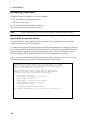
Document Scope
This document describes and specifies the “standard” version of the Agilent Multi-Cell
Charger/Discharger System. It contains installation instructions, connection information, programming
information, example programs, and specifications. Information about the Agilent MCCD User Interface
is provided online. System options are described on a separate option sheet that is shipped with this
manual. All information is this manual is subject to change. Updated editions will be identified by a new
printing date.
Notice
This document contains proprietary information protected by copyright. All rights are reserved. No part
of this document may be photocopied, reproduced, or translated into another language without the prior
consent of Agilent Technologies. The information contained in this document is subject to change
without notice.
Copyright 1999, 2000, 2001 Agilent Technologies, Inc.
4
Table of Contents
Warranty Information
Safety Summary
Document Scope
Table of Contents
1 - GENERAL INFORMATION
Agilent MCCD System Capabilities
Basic Functions
Additional Features
Hardware Description
Agilent E4370A MCCD Mainframe
Agilent E4374A and E4375A 64-Channel Charger/Discharger Cards
Agilent E4371A Powerbus Load
External Power Source
Multiple Agilent MCCD Configurations
Measurement Capability
Voltage Measurements
Current Measurements
Capacity Measurements
Cell Resistance
Probe Resistance
Data Logging
Protection Features
Internal Protection Functions
External Digital I/O Protection Functions
If AC Power Fails
Remote Programming Interface
Application Programming Interface (API)
Web Accessible Agilent MCCD User Interface
Example of a Cell Forming Process
2 - INSTALLATION
Inspection
Parts and Accessories
Location
Agilent E4370A MCCD Mainframe
Agilent E4371A Powerbus Load
Channel Connections
Voltage Drops and Wire Resistance
Remote Sense Connections
Power Bus Connections
Power Bus Wiring Information
Power Bus Configuration Examples
Digital Connections
General Purpose I/O
Special Functions
Wiring Guidelines
RS-232 Connections
Auxiliary Output Connection
Installing the API Library and Measurement Log Utility
Visual C++ Configuration
2
3
4
5
9
9
10
10
10
10
12
12
14
14
16
16
17
17
18
18
18
19
20
20
20
21
21
21
21
23
23
23
25
25
25
25
26
27
28
28
29
32
32
32
33
34
35
36
36
5
3 - CONFIGURATION
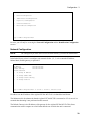
Configuring the LAN
1. Configure the HyperTerminal program
2. Connect the Agilent E4370A MCCD to the COM port on the PC
3. Fill Out the Agilent MCCD Configuration Screens
Network Configuration
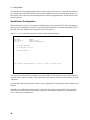
Identification Configuration
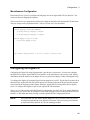
Miscellaneous Configuration
Configuring the Digital I/O
Mixed Configuration Example
Accessing Calibration
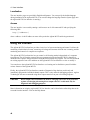
4 - AGILENT MCCD USER INTERFACE
Description
PC Requirements
Browser Settings
Security
Localization
Access
Using the Interface
Using the Agilent MCCD Measurement Log Utility
5 - PROGRAMMING OVERVIEW
A Cell Forming Overview
Cell Forming Example
Function Call Overview
Cell Grouping
Grouping Functions
Step/Test Functions
Sequence Control
Output Configuration
Instrument Protection
Power Fail Operation
Instrument State Storage
Status
Measurement Log
Time Stamp Function
Output Measurements
Direct output control
General Server functions
Selftest
Calibration
Serial port
Digital port
Probe check
6 - LANGUAGE DICTIONARY
API Usage Guidelines
API Function Summary
API Function Definitions
cfAbort
cfCal
cfCalStandard
6
37
37
37
38
38
39
40
41
41
44
44
45
45
45
45
45
46
46
46
47
49
49
50
53
53
54
54
55
56
57
58
58
59
60
61
61
62
62
63
63
64
64
65
67
67
68
70
70
70
70
cfCalTransfer
cfClose
cfDeleteGroup
cfGetCellStatus
cfGetCellStatusString
cfGetCurrent
cfGetDigitalConfig
cfGetDigitalPort
cfGetGroups
cfGetInstIdentify
cfGetInstStatus
cfGetMeasLogInterval
cfGetOutputConfig
cfGetOutputProbeTest
cfGetOutputState
cfGetRunState
cfGetSense
cfGetSenseProbeTest
cfGetSeqStep
cfGetSeqTest
cfGetSeqTestAnd
cfGetSeqTime
cfGetSerialConfig
cfGetSerialStatus
cfGetShutdownDelay
cfGetShutdownMode
cfGetStepNumber
cfGetTrigSource
cfGetUserIdentify
cfGetVoltage
cfInitiate
cfMeasACResistance
cfMeasCapacityAS
cfMeasCapacityWS
cfMeasCurrent
cfMeasDCResistance
cfMeasOutputProbeResistance
cfMeasProbeContinuity
cfMeasSenseProbeResistance
cfMeasVoltage
cfOpen
cfOpenGroup
cfProtect
cfProtectClear
cfReadMeasLog
cfReadSerial
cfReadTestLog
cfReset
cfResetSeq
cfRestart
cfSaveOutputConfig
cfSelftest
cfSetAutoConnect
cfSetCurrent
cfSetDigitalConfig
71
71
71
72
72
72
73
73
73
74
74
75
75
75
76
76
76
77
77
77
78
78
78
78
79
79
79
79
79
80
80
80
80
81
81
81
81
82
82
83
83
83
84
84
84
86
87
87
87
88
88
88
89
89
90
7
cfSetDigitalPort
cfSetErrorFunction
cfSetGroup
cfSetMeasLogInterval
cfSetOutputConfig
cfSetOutputProbeTest
cfSetOutputState
cfSetSense
cfSetSenseProbeTest
cfSetSeqStep
cfSetSeqTest
cfSetSeqTestAnd
cfSetSerialConfig
cfSetServerTimeout
cfSetShutdownDelay
cfSetShutdownMode
cfSetTimeout
cfSetTrigSource
cfSetVoltage
cfShutdown
cfStateDelete
cfStateList
cfStateRecall
cfStateSave
cfTrigger
cfWriteSerial
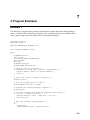
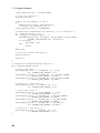
7 - C PROGRAM EXAMPLES
Example 1
Example 2
Example 3
92
92
93
93
93
94
94
95
95
95
97
99
99
99
100
100
100
100
100
101
101
102
102
102
102
103
105
105
107
112
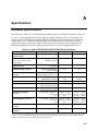
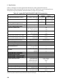
A - SPECIFICATIONS
115
B - CALIBRATION
119
Calibration Types
Full Calibration
Transfer Calibration
Mainframe Reference Calibration
Calibration Connections
Accessing Calibration
Calibration Error Messages
119
119
120
120
120
122
123
C - DIMENSION DRAWINGS
125
D - SENSE AND POWER CONNECTOR PINOUTS
127
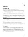
E - IN CASE OF TROUBLE
135
Introduction
Selftest Error Messages
INDEX
8
135
136
137
1
General Information
Agilent MCCD System Capabilities
The Agilent Multi-Cell Charger/Discharger (MCCD) System has been designed to address the unique
requirements and needs of lithium-ion cell manufacturing. The Agilent MCCD System can accurately
charge, discharge, and measure lithium ion cells. It consists of an Agilent E4370A Multi-Cell
Charger/Discharger mainframe with up to four Agilent E4374A or E4375A 64-Channel
Charger/Discharger cards. When fully loaded each mainframe has 256 input/output channels.
Mainframes and modules can be combined in different configurations to form a low cost, high
performance cell charge/discharge station in a cell manufacturing process.
NOTE:
You cannot mix Agilent E4374A and E4375A 64-Channel Charger/Discharger cards in
the same E4370A mainframe. Mainframes can only operate with identical-model cards.
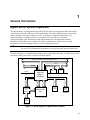
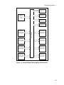
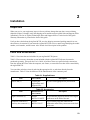
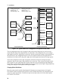
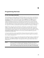
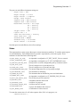
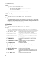
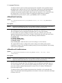
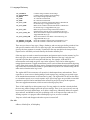
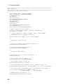
The following figure is a simplified block diagram of the Agilent MCCD System. It is followed by a brief
description of the system’s basic as well as advanced features.
10 Base T Ethernet to remote monitoring and control
Powerbus
Digital I/O to outside world
Serial
Multiple cell
tray
Serial
Fixture
control and
local
start/stop
Powerbus
Load
Multi-cell
charger /
discharger
Sense
Digital I/O
Local
Rail power
source
Power
Remote
Local
terminal
Local
barcode
reader
Local
controls
Figure 1-1. Block Diagram of Agilent MCCD System
9
1 - General Information
Basic Functions
♦
♦
♦
♦
♦
♦
Charger – The Agilent MCCD can deliver accurately controlled current and voltage into a cell for
proper forming. Each cell is independently paced through the cell forming sequence. This means that
some cells can be charging and others discharging if they are at different points in the sequence.
Discharger – The Agilent MCCD can draw accurately controlled current from a cell for both
forming and capacity measurement.
Measurement – The Agilent MCCD can monitor several parameters of the cell while charging,
discharging, and resting. Measurements include voltage, current, time, internal resistance, amperehours, and watt-hours. These measurements are used to adjust the cell forming sequence for safety,
reliability, and or proper cell forming.
Digital I/O control – The Agilent MCCD can monitor and stimulate digital I/O connected to it. This
simplifies wiring, allows ease of expansion, and is more reliable than a centralized control system. Its
high-speed capability is ideal for fast fault detection and system shutdown.
RS-232 control – The Agilent MCCD can support peripherals connected to its serial ports for adding
printers, bar code readers, local terminals, robots and other types of local additional hardware via
pass-through control from the host computer.
Equipment Protection – The Agilent MCCD has extensive safety features to protect both the cells
under formation and the hardware from equipment failure, programming errors, cell failures and
other types of external faults.
Additional Features
♦
♦
♦
♦
♦
♦
♦
LAN 10 base-T control using a web-server graphical user interface and an application programming
interface (API).
Comprehensive data storage capability and remote data collection.
Easily removable charger/discharger cards for minimum downtime if repair is required.
Charge/discharge sequences that can be modified in software, allowing for simple, rapid changes to
the manufacturing process without changes to system hardware.
Define and configure groups of contiguous blocks of cells or channels. This lets you simultaneously
run different sequences on groups of cells.
Continuous calibration is performed on the programming circuits during the entire charge/discharge
sequence to eliminate errors due to temperature drift.
Bi-directional power transfer and reuse of energy by using energy from discharging cells to provide
energy to charging cells.
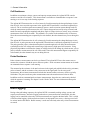
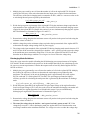
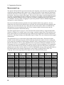
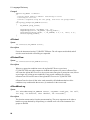
Hardware Description
Agilent E4370A MCCD Mainframe
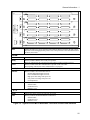
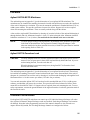
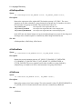
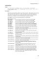
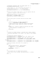
The Agilent E4370A MCCD mainframe is a full-width rack box that has 4 slots to hold either the Agilent
E4374A or Agilent E4375A 64-Channel Charger/Discharger cards. LEDs on the front of the mainframe
indicate system as well as card status (see Figure 1-2).
10
General Information - 1
E4370A
MULTICELL CHARGER/DISCHARGER
E4374A CHARGER/DISCHARGER
1
3
5
7
E4374A CHARGER/DISCHARGER
2
4
6
8
1
3
5
7
2
4
6
8
E4374A CHARGER/DISCHARGER
1
3
5
7
2
4
6
8
E4374A CHARGER/DISCHARGER
1
3
5
7
2
4
6
8
1
Ready
Fault
2
SYSTEM
Power
Ready
Ready
Fault
Active
FAULT
External
Internal
3
Ready
Fault
LINE
On
4
Ready
Fault
Off
LINE
Applies and removes ac power from the Agilent MCCD. Relays inside the unit that connect
the power bus are disengaged when power is off, so the power bus is also disconnected from
the unit by this switch.
SYSTEM
Power
When lit, indicates that the mainframe is powered on.
Ready
When lit, indicates that the unit is ready for operation.
When off, indicates that the external power bus voltage is either too high or too low.
Active
When lit, indicates that data communication is present on the LAN cable.
When flashing, indicates that LAN communication is in progress.
FAULT (Refer to Appendix E to clear any fault conditions)
External
When lit, indicates an external fault such as:
External digital fault signal received,
Power fail shutdown signal received,
High power bus voltage after power on,
Low power bus voltage after power-on.
Overtemperature
Internal
When lit, indicates an internal hardware fault such as:
Selftest failure,
Calibration error,
Hardware error.
1, 2, 3, 4
Ready
Indicates the card is powered up and ready to be used
Fault
When lit, indicates an internal hardware fault such as:
Selftest failure,
Calibration error,
Hardware error.
Figure 1-2. Agilent E4370A MCCD Mainframe Front Panel Controls and Indicators
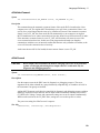
11
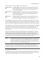
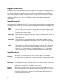
1 - General Information
A
B
C
D
E
F
RS-232
RS-232
PORT A
PORT B
G
H
J
A
B
C
D
E
F
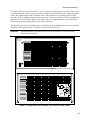
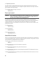
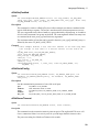
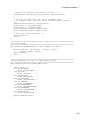
+ and - Power bus connectors
(- bus bar is connected to chassis ground)
Calibration status LEDs
Configuration switches
Transfer Calibration switch
Digital I/O connectors
LAN connection
K
G
H
J
K
RS-232 connectors (ports A and B)
AC line connection (a universal AC input for line
voltages from 87 Vac to 250 Vac, 50/60 Hz.)
Auxiliary output connection
Calibration port
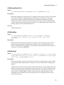
Figure 1-3. Agilent E4370A MCCD Mainframe Rear Panel Connections
Agilent E4374A and E4375A 64-Channel Charger/Discharger Cards
The Agilent E4374A and 4375A 64-Channel Charger/Discharger cards contain the circuitry that
independently charges and discharges each cell connected to the front of the mainframe. Up to four
identical-model cards can be installed in each mainframe. Agilent E4374A cards charge cells at at up to
5V and 2A. Agilent E4375A cards charge cells at up to 5V and 3A.
Each output channel has a maximum available compliance voltage of 5.5V for Agilent E4374A cards and
6.0V for Agilent E4375A cards. Compliance voltage is defined as the voltage required at the cell plus
any fixture/wiring voltage drops. Having this higher compliance voltage allows the full programmable 5
V to be applied directly to the cell with up to 0.5-volt loss in the wiring for Agilent E4374A cards and up
to 1.0-volt loss in the wiring for Agilent E4375A cards.
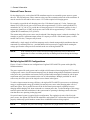
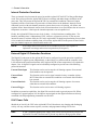
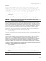
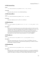
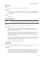
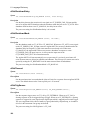
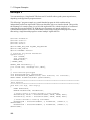
Agilent E4371A Powerbus Load
For the discharging cycle, an Agilent E4371A Powerbus Load is required to dissipate excess power from
discharging cells. The load operates in constant voltage mode only and sequentially switches internal
resistors on and off to regulate the voltage on the power bus around a midpoint of 26.75 volts. The
number of load units required depends on the number of Agilent MCCD mainframes in your system.
Each Agilent E4371A Powerbus Load is capable of the dissipating the full power from eight Agilent
E4374A 64-Channel Charger/Discharger cards or eight Agilent E4375A 64-Channel Charger/Discharger
cards.
12
General Information - 1
The Agilent E4371A Powerbus Load has a + and a − power bus connector on its rear panel. There is also
a ground connection. To meet safety requirements, connect the ground terminal of the Agilent Powerbus
Load to the ground terminal of the external dc source. The load receives its operating power from the
power bus. If the dc voltage on the power bus drops below 22.8 volts, or if there is no power available on
the power bus, the load will not operate. Note that the load is not programmable. It is set at the factory
for the correct operating voltage and does not require calibration.
The On/Off switch on the load simply connects or disconnects the load from the power bus. Note that the
internal fans draw approximately 1.5 amperes of current from the power bus.
CAUTION:
When discharging its maximum rated power, the Agilent E4371A Powerbus Load
becomes hot to the touch.
E4372A
POWERBUS LOAD
Figure 1-4. Agilent E4371A Powerbus Load Front and Rear Panels
13
1 - General Information
External Power Source
For the charging cycle, each Agilent MCCD mainframe requires an external dc power source to power
the cells. The external power source connects to the power bus terminals on the back of the mainframe. It
must be rated at 24 volts and be able to source 125% of the required cell charging power.
For example, to provide the cell charging power for a 256-channel system at 5.5 volts, 2 amperes per
channel (or 2.8 kW), the dc power source must deliver approximately 3.5 kW to each Agilent MCCD
mainframe (24 V @ 146 A). To provide the cell charging power for a 256-channel system at 6 volts, 3
amperes per channel (or 4.6 kW), the dc power source must deliver approximately 5.76 kW to each
Agilent MCCD mainframe (24 V @ 240 A).
The current rating of the power source may be reduced if the charging current is reduced accordingly. For
example, to provide a maximum output current of 1 ampere per cell in a 256-channel system, a source
rated at least 24 volts, 72 amperes may be used.
Additionally, a single supply of sufficient amperage may be shared among multiple mainframes that are
connected to a common power bus - provided that the total current can be supplied while meeting the
voltage specification at the power bus terminals at the rear of the Agilent MCCD.
NOTE:
If the external dc power source has an overvoltage protection circuit, it must be set
higher than 30 volts to avoid the possibility of shutting itself down during the discharge
cycle.
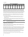
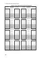
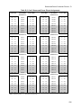
Multiple Agilent MCCD Configurations
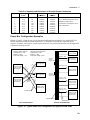
Figures 1-5 and 1-6 illustrate two configurations of Agilent E4370A MCCD systems with eight fully
loaded mainframes.
The power required for such systems can be as high as 46 kilowatts (when using Agilent E4375A cards).
A single power source of sufficient total amperage may be shared among multiple mainframes connected
to the power bus, provided the total current can be provided while meeting the nominal 24-volt dc input
requirement at the power bus terminals on the rear of each mainframe. Multiple paralleled 24-volt dc
sources may be used in place of the single dc source shown in the figures.
To achieve improvements in energy efficiency, the Agilent E4370A MCCD system can re-use discharge
energy to supplement the energy provided by an external power source when charging other cells in a
multi-unit system. This is possible because of the bi-directional power transfer capability between
charging and discharging cells when connected to a common power bus. To take advantage of this energy
transfer requires that some mainframes in the system must be operating in discharge mode at the same
time that others are operating in charging mode.
No special control system is required for this configuration. The regulation circuits of the 24 volt dc
power source, the Agilent E4370A MCCD mainframe, and Agilent E4371A Powerbus Load will operate
properly without any special hardware control lines or additional software being required.
NOTE:
14
Adequate size power bus wiring is required to carry high currents. Refer to Table 2-5.
General Information - 1
Agilent E4371A
Powerbus Load
Agilent E4371A
Powerbus Load
28 kW
Power Source
(24 V @
1167A)
Agilent E4371A
Powerbus Load
Agilent E4371A
Powerbus Load
Agilent E4370A
(256 channels)
Agilent E4370A
POWERBUS
+4 E4374A cards
+4 E4374A cards
(256 channels)
Agilent E4370A
Agilent E4370A
+4 E4374A cards
+4 E4374A cards
(256 channels)
(256 channels)
Agilent E4370A
Agilent E4370A
+4 E4374A cards
+4 E4374A cards
(256 channels)
(256 channels)
Agilent E4370A
Agilent E4370A
+4 E4374A cards
+4 E4374A cards
(256 channels)
(256 channels)
Figure 1-5. System Diagram Using Agilent E4374A Cards
15
1 - General Information
Agilent E4371A
Powerbus Load
Agilent E4371A
Powerbus Load
46 kW
Power Source
(24 V @
1920A)
Agilent E4371A
Powerbus Load
Agilent E4371A
Powerbus Load
Agilent E4370A
(256 channels)
Agilent E4370A
Agilent E4370A
POWERBUS
+4 E4375A cards
+4 E4375A cards
(256 channels)
Agilent E4370A
+4 E4375A cards
+4 E4375A cards
(256 channels)
(256 channels)
Agilent E4370A
Agilent E4370A
+4 E4375A cards
+4 E4375A cards
(256 channels)
(256 channels)
Agilent E4370A
Agilent E4370A
+4 E4375A cards
+4 E4375A cards
(256 channels)
(256 channels)
Figure 1-6. System Diagram Using Agilent E4375A Cards
Measurement Capability
The Agilent MCCD mainframe and charger/discharger cards have a high speed scanning system that
makes voltage and current measurements on all channels. Refer to Appendix A for technical data about
the measurement system. The following measurements are available:
Voltage Measurements
The Agilent MCCD measures the voltage of each channel using a calibrated internal measurement
circuit. In local sensing mode, the voltage measurement is made at the power connector. In remote
sensing mode, the voltage is measured at the end of the remote sense leads. The advantage of remote
16
General Information - 1
sensing over local sensing is that when the remote sense leads are connected to the cell, the actual voltage
of the cell will be measured. Any voltage drops in the load leads will not affect the measurement. Refer
to chapter 2 under "Remote Sensing" for more information.
NOTE:
If your Agilent MCCD system is configured for local sensing, the measured output
voltage may not reflect the actual voltage at the cell. This is because any voltage drops in
the wires due to wire resistance, probe resistance, connector resistance, etc. will reduce
the available voltage at the cell.
Current Measurements
The Agilent MCCD measures actual current in the output current path for each channel using a calibrated
internal measurement circuit.
Capacity Measurements
Amp-hour capacity - the Agilent MCCD determines amp-hour cell capacity by making calculations
based on continuous current measurements.
During charge, every time the Agilent MCCD makes a measurement, it calculates the actual incremental
amp-hours put into the cell during each measurement interval by multiplying the measured current times
the measurement interval. It then adds this incremental amount to the accumulated amp-hour value to
determine the total amp-hours delivered into the cell. Amp-hour capacity will be positive during charge.
Thus, accurate amp-hour capacity measurements can be made even when charge current is not constant,
such as during constant voltage charging.
During discharge, every time the Agilent MCCD makes a measurement, it calculates the actual
incremental amp-hours taken out of the cell by multiplying the measured current times the measurement
interval. It then adds this incremental amount to the accumulated amp-hour value to determine the total
amp-hours removed from the cell. Amp-hour capacity will be negative during discharge. Thus, accurate
amp-hour capacity measurements can be made even when discharge current is not constant.
Watt-hour capacity - the Agilent MCCD determines watt-hour cell capacity by making calculations
based on continuous current and voltage measurements.
During charge, every time the Agilent MCCD makes a measurement, it calculates the actual incremental
watt-hours put into the cell during each measurement interval by multiplying the measured current times
the measured voltage times the measurement interval. It then adds this incremental amount to the
accumulated watt-hour value to determine the total watt-hours delivered into the cell. Watt-hour capacity
will be positive during charge. Thus, accurate watt-hour capacity measurements can be made even when
charge current and voltage is varying.
During discharge, every time the Agilent MCCD makes a measurement, it calculates the actual
incremental watt-hours taken from the cell during each measurement interval by multiplying the
measured current times the measured voltage times the measurement interval. It then adds this
incremental amount to the accumulated watt-hour value to determine the total watt-hours taken from the
cell. Watt-hour capacity will be negative during discharge. Thus, accurate watt-hour capacity
measurements can be made even when discharge current and voltage is varying.
17
1 - General Information
Cell Resistance
In addition to continuous voltage, current, and capacity measurements, the Agilent MCCD can also
measure ac and dc cell resistance. This measurement is available on command when a sequence is not
running, or as its own step in the forming sequence.
The Agilent MCCD measures the ac cell resistance by first disconnecting the charge/discharge circuits
from all cells. An ac waveform generator in the Agilent MCCD mainframe is connected sequentially to
each cell. The ac waveform generator momentarily passes a small excitation current through each cell
while the measurement system measures the cell’s output voltage and current. By using a narrow band
tuned filter and computing the magnitude and phase angle of voltage relative to current, an ac resistance
measurement of the cell can be made. This method is very similar to the method used by LCR meters.
Since this measurement happens sequentially for each channel, the other channels stay at rest during this
test.
The Agilent MCCD measures the dc cell resistance by first disconnecting the charge/discharge circuits
from all cells. A pulse generator in the Agilent MCCD mainframe is connected sequentially to each cell.
The pulse generator passes a short-duration pulsed current through each cell while the measurement
system digitizes the cell voltage and current using a high accuracy, high-speed A/D converter. Using
proprietary algorithms to calculate the change in voltage relative to the change in pulsed current, a dc (or
pulse) resistance measurement of the cell can be made. Since this measurement happens sequentially for
each channel, the other channels stay at rest during this test.
Probe Resistance
Probe resistance measurements can also be performed. The Agilent MCCD uses the remote sense to
measure the resistance of both the power and sense probes. Probe resistance measurements can be made
on command when a sequence is not running.
The measured probe resistance is the total resistance in the signal path, which includes wiring resistance,
probe resistance, and the resistance of any connectors in the signal path. For the sense probe
measurement, the resistance measurement includes the internal scanner resistance, which is typically
1000 ohms. The power and sense probe measurements return the actual measured value in ohms.
In addition to the on-command probe resistance measurements, the probes are continuously checked
while the sequence is running. See chapter 5 under “Probe Check” for more information about probe
check verification.
Data Logging
During a charge/discharge sequence, the Agilent MCCD is constantly making voltage, current, and
capacity measurements. Instead of logging each and every measurement into a data buffer, the data
logging can be controlled so that only critical measurements are logged to the data buffer. This is called
event-based data logging, which means that whenever an important event occurs, a data log record will
be written into the data buffer. Buffer memory is used most efficiently when only critical measurements
are stored.
18
General Information - 1
The following events can be used to trigger critical measurements:
Change in voltage
(∆
∆V)
If the trigger is ∆V, a data log record will be written to the buffer when a userspecified voltage change is exceeded. If ∆V is set to 100 mV, then each time the
voltage reading changes by more than 100 mV from the last logged entry, a
record is written to the buffer.
Change in current
(∆
∆I)
If the trigger is ∆I, a data log record will be written to the buffer when a userspecified current change is exceeded. If ∆I is set to 100 mA, then each time the
current reading changes by more than 100 mA from the last logged entry, a
record is written to the buffer.
Change in time
(∆
∆t)
If the trigger is ∆t, a data log record will be written to the buffer when a userspecified time interval is exceeded. If ∆t is set to 1 second, then every second a
record is written to the buffer. ∆t is effectively a clock-driven data log.
The acceptable range of values for ∆V, ∆I and ∆t are 0 to infinity. Setting the value to 0 or near 0 will
cause all readings to be logged in the buffer, because every reading will exceed the ∆V, ∆I or ∆t value of
zero. This will fill up the measurement log very quickly. Setting the value to a high number or to infinity
will cause no readings to be logged in the buffer because no reading will exceed the ∆V, ∆I or ∆t value.
The comparison test to see if any of the ∆V, ∆I, and ∆t values have exceeded the values of the last logged
entry in the buffer is done at the end of each measurement interval. Therefore, the fastest rate at which
records can be written into the data buffer is the measurement rate of the Agilent MCCD. Any
combination of events can be specified, so that a data log record is written into the data buffer when any
of the events occur.
Each record in the data buffer contains the following information: status (including CV/CC and step
number), elapsed time, voltage, current, amp-hours, and watt-hours. The total number of readings that
can be stored is given in the specification table. The data log is a circular queue, which lets you
continuously log data into the data buffer. When the data buffer is full, the oldest data in the buffer will
be overwritten by new data. To avoid data loss, the controller must read the data from the buffer before it
is overwritten. Data can be read out of the data buffer at any time during the test sequence.
NOTE:
Information in the data buffer is lost when an ac power failure occurs. To prevent data
loss in the event of a power failure, use the cfShutdown function to save the data in nonvolatile memory. Refer to Power Fail Operation in chapter 5 for more information. To
allow the Agilent E4370A to ride through temporary ac power interruptions, connect the
mainframe to a 600 VA uninterruptible power supply (UPS).
A measurement log utility is included in the software that is provided with the Agilent E4373A
Documentation package. You can use this utility to read the data log and place the information in a file
on your PC. See chapter 4 for information on how to use the Agilent MCCD Measurement Log Utility.
Protection Features
The Agilent MCCD provides extensive capability to protect both the hardware and the individual cells
being formed from catastrophic damage. The Agilent MCCD can also communicate its protection status
to other parts of the manufacturing system for more sophisticated forms of protection.
19
1 - General Information
Internal Protection Functions
There are internal relays between the power bus and the Agilent E4374A/E4375A Charger/Discharger
cards. These relays protect the Agilent MCCD from overvoltage and undervoltage conditions on the
power bus. They also protect the Agilent MCCD if an external fault condition is detected. Output
regulators include several features to protect the cell from failures in the hardware. Internal circuits
connected in series with each channel protect the system from reverse cell polarity, cell failure, and
regulator failure. Internal thermal sensors check for maximum heat rise to avoid failures due to excessive
temperature excursions. A fan keeps the internal temperature at an acceptable level.
Finally, the Agilent MCCD has an extra level of safety - a built-in hardware watchdog timer. The
hardware watchdog timer is independent of CPU, software, or firmware activities. If, due to some
internal firmware or software fault, the CPU in the Agilent MCCD should stop functioning for more than
a few seconds, the hardware watchdog timer will reset the Agilent MCCD to the power-on state. In this
state, the channels outputs are disconnected from the cells.
NOTE:
Overvoltage and overcurrent tests can be included as part of a test sequence to
implement overvoltage and overcurrent protection (see chapter 5).
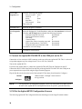
External Digital I/O Protection Functions
The Digital I/O subsystem on the Agilent MCCD can be configured to provide protection capabilities.
These digital I/O signals operate independently, so that if there is a problem with the computer or the
LAN connection the protection functions of the Agilent MCCD are not compromised. As explained in
chapter 2, the 16 digital I/O signals can be individually configured to provide one of the following
protection functions:
External Fault Input
This function can be used to stop the cell forming sequence if an external
fault condition sets the input true.
External Fault
Output
This function can be used to signal external circuitry or another Agilent
MCCD that either an external fault condition or an internal fault condition
has occurred.
External Interlock
This function can be used to stop the cell forming sequence for reasons
other than an external fault condition.
External Trigger
This function can be used to start a cell forming sequence.
In addition to protection capabilities, the digital I/O can also be used as general purpose I/O. When
configured as a general purpose I/O, the input or output signals on the digital connector are directly
controlled with API programming commands over the LAN.
If AC Power Fails
Should the ac line fail, the CPU in the Agilent MCCD will shut down. Any charging and discharging
activity will stop, and the current sequence, test data, and programmed settings will be lost.
Note:
20
A 600 VA uninterruptible power supply (UPS) can be used to provide ac power to the
Agilent E4370A MCCD mainframe to prevent any data loss during a power failure.
General Information - 1
When power fails, the power bus is also disconnected from the Agilent MCCD because of the bias
powered relays inside the Agilent MCCD. Thus, should a power failure occur which causes the Agilent
MCCD to lose ac power, in order to provide for safety, these internal relays would be disengaged and any
further charging or discharging would stop, even if the power bus were still powered and active.
Also, should a power failure occur which does not effect the Agilent MCCD but which causes the power
bus to drop in voltage, this will be detected by the Agilent MCCD as a power bus undervoltage condition
and the relays will open, thus preventing any further charging or discharging of connected cells.
Remote Programming Interface
The remote programming interface to the Agilent MCCD is through a LAN-based TCP/IP
communication protocol. The connection to the LAN is through a standard 8-pin 10Base-T connector on
the rear panel, which must first be configured according to the directions in chapter 3. The LAN
communication protocol is implemented in two ways:
Application Programming Interface (API)
The application programming interface runs under Windows 95 or Windows NT 4.0 using supplied Clanguage function calls. These function calls are documented in chapters 5 and 6, and provide the most
comprehensive method of controlling the Agilent MCCD. The API interface is the preferred method of
control when the Agilent MCCD is connected to a remote computer as part of an automated
manufacturing process.
Web Accessible Agilent MCCD User Interface
The Agilent MCCD has a built-in web server with a graphical user interface that is accessed through
standard web browsers such as Netscape Navigator version 3.03 and up or Microsoft Internet Explorer
version 3.02 and up. This Agilent MCCD User Interface allows monitoring of individual cell state,
measuring cell voltages and currents while the test is running, and also complete monitoring and control
of test status. The Agilent MCCD User Interface is the preferred method of control when evaluating the
test system, prototyping a process, or debugging a program.
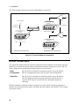
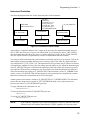
Example of a Cell Forming Process
The Agilent E4370A MCCD is designed to be the integral part of a complete cell forming process as
shown in Figure 1-7. As shown in the figure, many of the previously mentioned protection and external
signal capabilities of the Agilent E4370A MCCD are implemented using the digital I/O connections. The
serial ports on the back of the Agilent MCCD are used to control local peripherals directly from the host
computer. The remote programming interface to the Agilent MCCD lets you seamlessly integrate all of
these capabilities into the cell forming process.
The following cell forming example describes how an Agilent E4370A MCCD may be used to run a
semi-automated process where the only human actions required are: entering data with a barcode
scanner, loading and unloading a test fixture, and manually starting the cell forming process. Chapters 5
and 6 describe all of the function calls that are available to implement a cell forming process.
21
1 - General Information
LAN
Powerbus
Dig I/O for fire/smoke detector
Dig I/O for fixture
open/close
Control PC
H
Fixture
Dig I/O for
buttons and
indicators
MCCD
Ready Test
Tray of cells
Start
Power + Sense lines
Bar Code Scanner
Serial
communications
Figure 1-7. Typical Cell Forming Station
♦
♦
♦
♦
♦
♦
♦
♦
♦
The control PC sends a signal via the LAN to the digital I/O to turn on the Ready light on the test
fixture. This tells the operator that the system is ready for another tray of cells. The control PC also
begins polling for serial data on the RS-232 buffer of the Agilent MCCD.
The operator scans the bar code on the tray of cells sitting on the conveyor belt. The operator then
loads the tray into the test fixture and closes the fixture.
After detecting that data is available on the RS-232 buffer, the control PC reads the bar code data.
Based on the data, it downloads the correct forming sequence into the Agilent MCCD. It also
downloads setup information such as which channel outputs to enable, probe check settings, trigger
source, etc.
The control PC then polls the digital I/O lines for the Start button.
When the operator presses Start, the control PC detects it and polls the digital I/O lines to make sure
the fixture is closed. It sends a signal to turn off the Ready light and turn on the Test light, indicating
to the operator that the cell forming sequence has started.
The control PC then sends a trigger to the Agilent MCCD to start the forming sequence. It also starts
polling the instrument status for the completion of the test sequence.
The cell forming sequence runs. The test sequence automatically applies a stimulus to the cells,
monitors cell parameters to determine if a cell passes or fails, and stores the test results. During the
test sequence, the Agilent MCCD monitors the dedicated digital I/O lines that are connected to the
fire and smoke detectors. This allows rapid response in case of a problem.
When the instrument status in the Agilent MCCD shows that the sequence is complete, the control
PC sends commands to the Agilent MCCD to measure the internal resistance of all cells and then
upload all measurement data.
Finally, the control PC sends a signal to turn off the Test light and light the Ready light. The
operator knows that it is now safe to remove the tray from the fixture and start another batch.
Chapter 7 contains several programming examples written in C. The purpose of these examples is to
show you how to implement the various functions of the Agilent MCCD so that you can develop your
own application programs. Program #2 matches the example described here.
22
2
Installation
Inspection
When you receive your equipment, inspect it for any obvious damage that may have occurred during
shipment. If there is damage, notify the shipping carrier and the nearest Agilent Sales and Support Office
immediately. The list of Agilent Technologies Sales and Support Offices is at the back of this guide.
Warranty information is printed in the front of this guide.
Until you have checked out the Agilent MCCD, save the shipping carton and packing materials in case
the unit has to be returned. If you return the Agilent MCCD for service, attach a tag identifying the model
number, serial number, and the owner. Also include a brief description of the problem.
Parts and Accessories
Table 2-1 lists items that are included with your Agilent MCCD System.
Table 2-2 lists accessory items that are not included with the Agilent MCCD System, but must be
purchased separately. Except for the User’s Guide, all of these items are required to make connections
from the Agilent MCCD to either the computer, test fixture, or external devices that will be controlled by
the Agilent MCCD.
You can either order these items by ordering the appropriate kit, or order them directly from the
manufacturer. Table 2-3 lists the addresses of the manufacturers of the connector parts.
Table 2-1. Supplied Items
Item
Power Cord (1)
Part Number
Contact your
Agilent Sales and
Support office
Description
A power cord appropriate for your location.
Table 2-2. Accessories
Item
Manufacturer’s
Part Number
Description
Digital connectors (2)
Phoenix
MSTB-2.5/10-STF
10-pin terminal plugs that connect to the digital
connectors on the back of the unit.
Calibration connector (1)
Auxiliary bias connector (1)
Phoenix
MSTB-2.5/4-ST
4-pin terminal plugs that connect to the
calibration and auxiliary connectors on the back
of the unit.
23
2 - Installation
Table 2-2. Accessories (continued)
Item
Manufacturer’s Part
Number
Description
Documentation Package
Agilent E4373A
Contains user documentation, software
drivers, and utility programs .
Serial cable
Agilent 34398A
RS-232 null-modem cable for port A or B.
(see figure 2-4 for schematic)
37-pin
D-sub connector
AMP 205210-2
Mating connector for front panel channel
connectors. Eight connectors are required
for each 64-channel card.
(Connector pins on 64-channel cards are
rated at 5 A maximum.)
Connector hood for 37pin connector
AMP 749916-2
Eight connector hoods are required for each
64-channel card.
Crimp style contacts for
37-pin connector
AMP 66506-9
Crimp contact for 37 pin connector
16 contacts are required for each connector.
(Pins only accept wires sized 20-24 AWG.)
Crimp tool for crimp
style contacts
AMP 58448-2
Hand crimp tool
Solder style contacts for
37-pin connector
AMP 66570-2
Crimp contact for 37 pin connector
16 contacts are required for each connector.
No tooling is required.
(Pins only accept wires sized 18 AWG.)
Front Panel Filler Panel
Agilent p/n 5002-1505
One blank filler panel is required for every
empty slot in Agilent MCCD mainframes.
Rack mount Flange Kit
Agilent p/n 5062-3979
Includes 2 flanges, fasteners, and mounting
screws
Rack mount Flange Kit
with Handles
Agilent p/n 5062-3985
Includes 2 handles, 2 flanges, fasteners, and
mounting screws
Table 2-3. Manufacturer's Addresses
Company
Address
Contact
Phoenix Contact
P.O. Box 4100
Harrisburg, PA 17111-0100
Phone:717-944-1300
Fax: 717-944-1625
http://www.phoenixcontact.com/index.html
AMP
Harrisburg, PA 17111
http://www.amp.com/
Agilent Technologies
See list at back of this manual
http://www.agilent.com/
24
Installation - 2
Location
Agilent E4370A MCCD Mainframe
The outline diagrams in Appendix C give the dimensions of your Agilent MCCD mainframe. The
mainframe may be installed free-standing, but must be located with sufficient space at the sides and back
of the unit for adequate air circulation. You can rack mount the mainframe in standard 600 mm (23.8 in.)
width system cabinets. This provides sufficient clearance for airflow. Support rails are also required
when rack mounting the mainframe. These are usually ordered along with the cabinet.
A fan cools the Agilent MCCD mainframe by drawing air in on the left side of the unit and discharging it
through the back and side. Minimum clearance is 9 cm (3.5 inches) along the sides. Minimum clearance
behind the mainframe is 23 cm (9 inches). Do not block the fan exhaust at the rear or the side.
NOTE:
To ensure proper cooling of the Agilent MCCD mainframe, there should be no open slots
in the front of the mainframe. If an Agilent 64-Channel Charger/Discharger Card is
either not installed or has been removed from a slot, a blank filler panel must be installed
in the opening. Refer to Table 2-2.
Agilent E4371A Powerbus Load
CAUTION:
To ensure adequate airflow to cool the Agilent Powerbus Load requires you to leave 0.6
meters (2 feet) of open space in front of the load and directly behind the load. If you are
rack-mounting the load, leave the rack door off.
When discharging its maximum rated power, the Agilent E4371A Powerbus Load
becomes hot to the touch.
The outline diagrams in Appendix C give the dimensions of your Agilent Powerbus Load. The unit may
be installed free-standing, but must be located with sufficient space at the front and back of the unit for
adequate air circulation. Fans cool the unit by drawing air in on front and discharging it through the back.
Maximum airflow is 10 cubic meters per minute (350 cubic feet per minute).
You can rack mount the Agilent E4371A Powerbus Load in standard 600 mm (23.8 in.) width system
cabinets, provided that you remove the rear door. This provides sufficient clearance for airflow. Rack
mount kits are described in Table 2-2. Support rails are required when rack mounting the unit. To meet
safety requirements, connect the ground terminal of the Agilent Powerbus load to the ground terminal of
the external dc source.
Channel Connections
Each Agilent E4370A MCCD mainframe can control up to 256 individual charge/discharge cells when
four Agilent 64-Channel Charger/Discharger cards are installed. Each charger/discharger card contains
64 channels. Note that in the programming sections of this manual, channels are also referred to as
outputs. When fully loaded, the 256 charge/discharge channels are configured as follows:
25
2 - Installation
Table 2-4. Channel Configuration
Card
Connector Number
Number
1
2
3
4
5
6
7
8
1
1-8
9 - 16
17 - 24
25 - 32
33 - 40
41 - 48
49 - 56
57 - 64
2
65 - 72
73 - 80
81 - 88
89 - 96
97 - 104
105 - 112
113 - 120
121 - 128
3
129 - 136
137 - 144
145 - 152
153 - 160
161 - 168
169 - 176
177 - 184
185 - 192
4
193 - 200
201 - 208
209 - 216
217 - 224
225- 232
233 - 240
241 - 248
249 - 256
Power connections on each Agilent 64-Channel Charger/Discharger Card are through eight 37 pin Dsubminiature connectors. These connectors allow for shielding and strain relief. Corresponding sense
connections are also available on the connectors. Refer to Table 2-2 for information about ordering the
mating connectors. As indicated in the table, mating connectors accept wire sizes from AWG 24 up to
AWG 18, depending on the type of connector that you are using. You must wire up the mating connector
to make your wire connections. Install the mating connector on the front of the charger/discharger card
when complete. Refer to Appendix D for detailed pinout assignments of the front panel connectors.
If specific channels are not being used, you can configure them to be inactive. Inactive channels are
open-circuited. Note that there are two ways to configure the channel outputs, each having different
effects when the unit is powered on.
♦
If you configure the channel outputs using the cfSetOutputConfig() function (see chapter 6), the
settings are NOT saved in non-volatile memory. Each time you power up the unit, you must
reprogram the settings.
♦
If you configure the channel outputs using the Sequence setup page in the Agilent MCCD User
interface (see chapter 4), the settings ARE saved in non-volatile memory. The unit will wake up with
those settings when it is powered up.
NOTE:
If the mainframe has empty card slots, the channels that are normally reserved for those
card slots will be treated as inactive channels.
Voltage Drops and Wire Resistance
Agilent E4374A Charger/Discharger Cards have a maximum of 5.5V and 2A available at the power
connector of each channel. Agilent E4375A Charger/Discharger Cards have a maximum of 6V and 3A
available at the power connector of each channel.
This means that at the rated output of 5V, the Agilent E4374A cards will tolerate up to a 0.5 volt drop,
and the Agilent E4375A cards will tolerate up to a 1.0 volt drop in the load leads due to wire resistance,
probe resistance, connector resistance, etc. Higher voltage drops will reduce the available voltage at the
cell. Proper wiring design including using larger gauge wires and low-resistance fixture contacts can
minimize voltage losses in the wiring and maximize the available voltage for charging the cells.
The length of the leads from the power connector to the cells is determined by how much voltage drop
your system can tolerate. The voltage drop is directly determined by the wire, connector, and probe
resistance (see table 2-5). Refer to Remote Sense Connections for more information.
To optimize performance and minimize the possibility of output instability and output noise, please
observe the following guidelines:
26
Installation - 2
♦
It is good engineering practice to either twist or shield the sense and power wires.
♦
Twist the power wires together and keep them as short as possible.
♦
Twist the sense wires together but do not twist them together with the power wires.
♦
If possible, shield the sense wires. Connect the shield to the case.
♦
Keep the total cable length as short as possible.
♦
Use low resistance fixture contacts.
Remote Sense Connections
The sense connections provide remote sense capability at the fixture. Sense connections on each card are
through the same connectors that house the power connections.
Remote sensing allows the output voltages to be sensed at the cell, thus compensating for any losses in
the wiring. On the Agilent E4374A cards, the compliance voltage (the voltage that the Agilent MCCD
can provide in excess of the programmable rating) can be up to 5.5 volts to compensate for any voltage
drop caused by resistance in the wiring between the channel output and the cell connections. On the
Agilent E4375A cards, the compliance voltage can be up to 6.0 volts.
The following table gives the resistance values of various wire sizes so that you can calculate the voltage
drops for various wire lengths and diameters. Larger and shorter wires result in lower voltage drops. The
table also gives an example of the maximum allowable wire lengths that can be used when taking the
compliance voltage capability of the charger/discharger cards into consideration. The voltage drop used
in the example is based on a minimum of 4.1 volts available to charge a typical lithium ion cell.
Table 2-5. Resistance of Stranded Copper Conductors
AWG No.
mm2
Resistance (at 20 deg. C)
Ω/m
Ω/ft
Maximum length in meters
(total length of + and - leads)
to limit voltage drop to:
1.4 V @ 2A
1.9 V @ 3A
18
0.825
0.022
0.0066
31
28
20
0.519
0.034
0.0105
20
18
22
0.324
0.055
0.0169
12
11
24
0.205
0.087
0.0267
8
7
As an example, assume that you are using AWG #24 wire for your power connections and your charging
voltage is 4.1 volts at 2 amperes. Using this diameter wire and assuming a maximum current of 2
amperes, the maximum distance from the power connector to the cell is limited to about 4 meters. This is
because with a total wire length of 8 meters for both the + and − power leads, the maximum voltage drop
in the wiring is 1.4 volts (2A X 0.7Ω). With a charging voltage of 4.1 volts required at the cell, this is the
maximum voltage drop that an Agilent E4374A card can tolerate. Note that the Agilent E4375A card can
tolerate up to a 1.9 volt drop in the load wiring.
NOTE:
This example does not account for any additional lead path resistance that may be
present such as fixture contact resistance, or fixture relays. If additional resistance is
present, lead length must be reduced yet further.
27
2 - Installation
Power Bus Connections
CAUTION:
Observe polarity when making the power bus connections to both the Agilent MCCD
mainframe and the Agilent Powerbus Load. Reversed polarity connections will result in
damage to both the Agilent MCCD mainframe and the Agilent Powerbus load. The
negative (−
−) bus bar on the Agilent MCCD mainframe is connected to chassis
ground.
Connections to the power bus are made via + and − bus bars on the back of the Agilent E4370A MCCD
mainframe and Agilent E4371A Powerbus Load units. These bus bars let you interconnect multiple
mainframes, external power sources, and other loads. Bus bars have mounting holes that accept 7 mm
diameter bolts.
NOTE:
Fasten a suitable terminal lug to each power bus cable. Do not connect bare wires
directly to the bus bars. Stranded cables with more and smaller diameter wires are easier
to work with than cables with fewer and large diameter wires.
When making your power connections you can use discrete terminated wires, bus bars, or combinations
of both. For proper operation all power bus configurations should have minimum loop area for low
magnetic radiation and should be kept away from CRTs. The following guidelines may be helpful in
deciding whether to use wires or bus bars.
Discrete terminated wires:
Are the better solution for connecting individual units to each other in small systems and to bus bars
in large systems.
♦ Have minimal alignment, insulation or routing problems.
♦ Are preferred for small cell charging systems.
♦
Bus bars:
♦
♦
♦
♦
Are the better solution for high current carrying requirements.
Can be custom designed or purchased; can use standard high current building parts.
Use nuts and bolts or self tapped holes for connections.
Require careful surface preparation and cleaning at connection points.
WARNING
ENERGY HAZARD. If high current power bus connections touch, severe arcing
may occur - resulting in burns, ignition, or welding of parts. Do not attempt to
make any connections to the power bus when the power bus is live.
Power Bus Wiring Information
The following table provides information about the resistance and ampacity of several standard wire
sizes that may be suitable for power bus connections. This information is important because the
resistance of the power bus wiring will cause a voltage drop in the power bus wires. If the voltage drop is
large enough, it may prevent the Agilent E4370A MCCD mainframe from operating correctly in charging
mode, or the Agilent E4371A Powerbus Load from operating correctly in discharging mode.
28
Installation - 2
Table 2-6. Ampacity and Resistance of Stranded Copper Conductors
AWG No.
Area
in mm2
5.26
8.36
13.3
21.1
33.6
53.5
67.4
85.0
107
10
8
6
4
2
1/0
2/0
3/0
4/0
Ampacity
Resistance
in Ω/meter
0.00327
0.00206
0.00129
0.00081
0.00051
0.00032
0.00025
0.00020
0.00016
40
60
80
105
140
195
225
260
300
Resistance
in Ω/feet
0.00099
0.00062
0.00039
0.00025
0.000156
0.000098
0.000078
0.000062
0.000049
Notes
1. Wire ampacities are based on
30° C ambient temperature with
conductor rated at 60° C.
2. Resistance is nominal at 20° C
wire temperature.
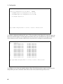
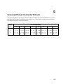
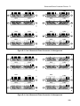
Power Bus Configuration Examples
Figures 2-1 and 2-2 illustrate two typical power bus configurations consisting of two Agilent E4370A
MCCD mainframes connected to one Agilent E4371A Powerbus Load and two external dc power
supplies. As shown in the figures, current requirements may vary widely based on the way the equipment
is connected to the power bus.
+
Charging values based on:
Power/channel = 11W
Efficiency = 80%
Power bus voltage = 24V
-
charging = 146A
+
Discharging values based on:
Power/channel = 9W
Efficiency = 80%
Power bus voltage = 26.5V
Power Source
(24
V @ 146 A)
_
charging = 146A
maximum
charging
current = 292A
+
14
6
Agilent E4370A
A
+
_
Power Source
(24 V @ 146 A)
discharging = 140A
_
Agilent E4371A
Powerbus Load
_
+
+
/70
6A
14
A
+
_
Terminal
Block
+4 E4374A cards
_
Power Source
146A _ (24 V @ 146 A)
maximum
discharging
current = 140A
charging = 146A
discharging = 70A
0A
14
Agilent E4370A
+
A
70
(256 channels)
(256 channels)
Power Source
_ (24 V @ 146 A)
/
6A
14
+4 E4374A cards
+
+
Agilent E4370A
+4 E4374A cards
+
(256 channels)
_
Agilent E4371A
Powerbus Load
charging = 146A
discharging = 70A
_
Flexible Wires
+
Agilent E4370A
+4 E4374A cards
(256 channels)
_
Rigid Bars
Flexible Wires
STAR CONFIGURATION
BUS BAR CONFIGURATION
Figure 2-1. Typical Power Bus Configuration for Agilent E4374A cards
29
2 - Installation
+
Charging values based on:
Power/channel = 18W
Efficiency = 80%
Power bus voltage = 24V
-
charging = 160A
+
Discharging values based on:
Power/channel = 13.5W
Efficiency = 75%
Power bus voltage = 26.5V
Power Source
_ (24 V @ 160 A)
charging = 160A
+
Power Source
_ (24 V @ 160 A)
+
160
A
_
8A
/9
0A
24
_
+4 E4375A cards
(256 channels)
_
Power Source
(24 V @ 160 A)
+
_
+
+
_
Power Source
160A _ (24 V @ 160 A)
maximum
discharging
current = 196A
A
Terminal
Block
_
charging = 240A
discharging = 98A
+
6A
+4 E4375A cards
(256 channels)
/98
0A
Power Source
_ (24 V @ 160 A)
discharging = 196A
19
24
+
Agilent E4371A
Powerbus Load
+
Agilent E4370A
charging = 160A
maximum
charging
current = 480A
16
0A
Agilent E4370A
+
+
Power Source
(24 V @ 160 A)
Agilent E4370A
+4 E4375A cards
+
(256 channels)
_
Agilent E4371A
Powerbus Load
charging = 240A
discharging = 98A
_
Flexible Wires
+
Agilent E4370A
+4 E4375A cards
(256 channels)
_
Rigid Bars
Flexible Wires
STAR CONFIGURATION
BUS BAR CONFIGURATION
Figure 2-2. Typical Power Bus Configuration for Agilent E4375A cards
The star configuration on the left is designed so that each section of the power bus carries no more
current than the rating of the equipment that it is connected to. This configuration lets you use longer
lead lengths because the voltage drop in each lead is directly related to the amount of current flowing in
the lead. However, this configuration requires you to run separate leads from each Agilent MCCD
mainframe to the load as well as the power supply, thus increasing the total amount of wiring required.
The bus bar configuration on the right is designed to minimize the amount of wiring between the
equipment. However this requires larger diameter wires or bus bars. This is because the leads from the
power supplies as well as the leads to the load are required to carry the full charging and discharging
current for two Agilent E4370A MCCD mainframes. Larger currents result in larger voltage drops in the
wiring, which may prove unacceptable with long lead lengths.
Charging Mode Guidelines:
Power bus wires must be capable of handing the full charging current requirements of all Agilent
E4370A MCCD units connected to the power bus. In the example that follows, the calculations are for
worst case current requirements. Calculate the input current requirement of one fully loaded Agilent
E4370A MCCD as follows:
30
Installation - 2
1. Multiply the power used by one cell times the number of cells in the Agilent MCCD. Divide the
result by the efficiency of the unit to determine the total input power required for that mainframe.
The efficiency of the unit in charging mode is assumed to be 80%, which is a worst-case value as far
as calculating the total power required by the mainframe.
#_of_cells × power_per_cell = Max_power_in
0.8
2. Divide the input power requirements of the Agilent MCCD by the minimum voltage required at the
input terminals of the Agilent MCCD (22.8 volts). The result will be the maximum charging current
required by the Agilent MCCD. (Double this current if you are simultaneously charging two Agilent
MCCD mainframes as illustrated in Figures 2-1 and 2-2.)
Max_ power_in
Power_source_voltage
= Max_powerbus_current
3. Determine the voltage drop that the maximum current will produce in the power bus leads using the
resistance values in Table 2-6.
4. Add this voltage drop to the minimum voltage required at the input terminals of the Agilent MCCD
to determine the output voltage setting of the dc power supply.
5. The voltage at the input terminals of the Agilent MCCD during charging mode must be between 25.2
and 22.8 volts. If the sum of the voltage drops in both the + and − power bus leads causes the voltage
at the mainframe power terminals to drop below 22.8 volts, the Agilent E4370A MCCD will shut
down due to an undervoltage condition. Use a larger size wire to reduce the voltage drop.
Discharging Mode Guidelines:
Power bus wires must also capable of handing the full discharging current requirements of all Agilent
E4370A MCCD units connected to the power bus. In the example that follows, the calculations are also
for worst case current requirements. Calculate the output current of one fully loaded Agilent E4370A
MCCD as follows:
1. Multiply the power generated by one cell times the number of cells in the Agilent MCCD. Multiply
the result by the efficiency of the unit to determine the total output power produced by that
mainframe. The efficiency of the unit in discharging mode is approximately 80% with Agilent
E4374A cards and 75% with Agilent E4375A cards. This percentage represents the highest
efficiency possible for calculating the total power that is generated by the mainframe in discharge
mode.
(#_of_cells × power_per_cell) × Efficiency = Max_power_out
2. Divide the power generated by the Agilent MCCD by the input voltage of the Agilent Powerbus
Load. At an input voltage of 26.5 volts, the result will be the maximum discharging current that will
be absorbed by the Agilent Powerbus Load. (Double this current if you are simultaneously
discharging two Agilent MCCD mainframes as illustrated in Figure 2-5.)
Max_ power_out
= Max_powerbus_current
26.5
3. Determine the voltage drop that the maximum current will produce in the power bus leads using the
resistance values in Table 2-6.
4. The sum of the voltage drops in both the + and − power bus leads cannot exceed 1.5V. If the
voltage drop exceeds 1.5 volts in discharging mode, the Agilent MCCD will shut down due to an
overvoltage condition at the mainframe terminals. Use a larger size wire to reduce the voltage drop.
31
2 - Installation
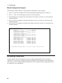
Digital Connections
Each Agilent E4370A MCCD mainframe has a 16-bit digital I/O port. Digital I/O configuration can be
done with the Agilent MCCD Configuration Screens as described in chapter 3 or with the Agilent MCCD
User Interface as described in chapter 4. All pins do not have to be configured the same. Some can be
used as isolated outputs while others are single ended I/O. The functions can also be mixed, some pins
can be general purpose I/O while others have a specific purpose. The polarity of a bit can also be
configured as either high true or low true. The following list documents the types of digital I/O
configurations:
General Purpose I/O
General purpose I/O programs the digital I/O as a passthrough function that allow input or output signals
on the digital connector to be directly controlled with API programming commands. These signals have
no effect on the cell forming sequence.
Digital
Output
When configured as outputs, each line is driven by an internal open collector
transistor. Output lines are capable of driving either TTL compatible inputs, or high
power loads such as solenoids, indicator lights, and relays. These are 24 V/ 300mA
compatible open-collector outputs.
Digital Input
When configured as inputs, each line can be driven by an external source. All lines are
TTL compatible inputs, with built in pull-ups to 5 V to facilitate contact and switch
closure style inputs.
Digital In/Out
When configured as in/out, each line can be used as both an input and an output.
Programming the line high allows an external device to drive the line. Programming
the line low drives the line low. Reading the line returns the actual state of the line.
Isolated
Output
When outputs are configured for optically isolated mode, they are open-collector
outputs capable of sinking 1.6mA at 0.4V, and can be used up to 24V. Adjacent pin
pairs starting with pin 0 are the plus and minus output of an optical isolator. This
allows for up to 8 isolated outputs, on adjacent pin pairs 0-1, 2-3, 4-5 etc. Because
these are dedicated pairs, pins 1 and 2 cannot be combined as an isolated output.
Special Functions
External
Fault Input
When true, this signal stops the cell forming sequence due to an external fault
condition. It also sets the external fault output signal true. This signal can be connected
to a sensor such as a fire detector. It can also be connected to the external fault output
of another Agilent MCCD so that it can respond to a fault in another mainframe.
External
Fault Output
This signal is asserted true when an external fault occurs. It can be connected to
external equipment such as a fire alarm. It can also be connected to the external fault
input of another mainframe so that a fault in one mainframe can shut down other
mainframes. A cfProtectClear command clears this signal.
External
Interlock
When true, this signal stops the cell forming sequence, but because the stop was not
due to a fault condition, it does not set the external fault output signal true. This levelsensitive signal can be connected to an external stop or pause switch to allow an
operator or mechanical device to stop a cell forming sequence. When the signal is
removed, the sequence continues.
32
Installation - 2
External
Trigger
This external trigger input is used to start the cell forming sequence.
Power Fail
Depending on how the system is configured, when true, this input signal will cause the
Agilent MCCD to perform a shutdown, at which time it saves its state for a later restart.
A power fail output signal is also available to indicate when the shutdown state has
been saved.
Wiring Guidelines
Connection for the 16 digital I/O signals are through two 10-pin Phoenix/Weidmuller style connectors.
The connectors have screw terminals for making wire connections and are detachable. Digital I/O lines 0
through 7 are on connector 1; digital I/O lines 8 through 15 are on connector 2. There are two common
terminals on each connector for ground or the return connection.
The following figure illustrates the internal circuits of the digital I/O connector. When used as a digital
input (A), the external circuit connected to the digital input pin can be TTL, AS, CMOS, HC, or a simple
switch that connects the digital input to the common terminal. When used as a digital output (B) the
external circuit connected to the output pin can also be TTL, AS, CMOS, HC or a warning light,
provided the light has an external bias supply.
When used as isolated pairs (C), each pin pair can be connected to external circuits with the following
restrictions: Only adjacent pairs can be used together. Only the even pin of each pair can be programmed
to set the logic level as low true or high true. When Low True is programmed, the output is true when the
pins are shorted. When High True is programmed, the output is true when the pins are open.
+5V
+5V
DIG I/O
Connector
4.7K
Dig In signal
4.7K
DIG I/O
Connector
Even Pin
Odd or Even Pin
A. Digital Input
+5V
Common
Isolated
Dig Out signal
4.7K
+5V
Adjacent
Odd Pin
4.7K
C. Isolated Output
Odd or Even Pin
Common
Dig Out signal
B. Digital Output
Figure 2-3. Equivalent Digital I/O Circuits
33
2 - Installation
The following figure illustrates some typical DIO hardware connections.
+ 16.5 V maximum
connect to pins
0 through 7
Coil current
0.25A maximum
7
6
5
4
3
2
1
0
7
6
5
4
3
2
1
0
TTL, AS, CMOS, HC
. . . . . . . . . .
Connect common to
connect to pins
2, 4, 6, 8
7
6
5
4
3
2
1
0
connect to pins
1, 3, 5, 7
connect to pins
0 through 7
7
6
5
4
3
2
1
0
Connect common to
A) Relay Driver Example Circuit
B) Digital Interface Example Circuit
Figure 2-4. Typical Hardware Connections
RS-232 Connections
The Agilent MCCD has two RS-232 ports for connection to local peripherals. Under normal operation
both ports are available for general purpose communications and are configurable over the LAN. For
initial configuration and calibration, the RS-232 ports are used as follows:
Initial
Configuration
RS-232 port B is connected to a terminal and used to access the Agilent
MCCD Configuration Screens. This sets up the initial configuration.
Calibration
RS-232 port B is connected to a terminal and used to access the Agilent
MCCD Configuration Screens through which the calibration process is
executed. RS-232 port A is used to connect a dedicated voltmeter for
calibration.
Both ports should be configured with the same baud rate as the computer. Both ports support full
hardware flow and software flow control with XON and XOFF support, and with RTS / CTS available
for hardware control.
34
Installation - 2
1
2
3
4
5
Pin
1
2
3
4
5
6
7
8
9
6 7 8 9
DB-9 male connector
Input/Output
Input
Output
Common
Output
Input
Description
no connection
Receive Data (RxD)
Transmit Data (TxD)
not used
Signal ground
not used
Request to Send (RTS)
Clear to Send (CTS)
no connection
Figure 2-5. RS-232 A and B Connectors
The following diagram describes the cable connections between the Agilent MCCD RS-232 ports and
any local peripherals such as a PC or barcode scanner. Refer to table 2-2 for cable kit information.
MCCD
NULL-MODEM CABLE
1
2
3
4
5
6
7
8
9
DCD
RXD
TXD
DTR
GND
DSR
RTS
CTS
RI
DB9 MALE
DB9 FEMALE
PC
(or serial device)
1
2
3
4
5
6
7
8
9
DB9 FEMALE
DCD
RXD
TXD
DTR
GND
DSR
RTS
CTS
RI
DB9 MALE
Figure 2-6. Null-modem Cable Connections
Auxiliary Output Connection
An undedicated isolated auxiliary output is provided to power various actuators and circuits local to the
test fixture. It can also be used as the pull-up source for any digital I/O connections that require an
external pull-up source. The auxiliary output is available through a 4-pin Phoenix/Weidmuller style
connector on the rear panel. The connector has screw terminals for making wire connections and is
detachable.
As explained in chapter 3, the Agilent MCCD Configuration Screens let you set this output to between 5
volts and 24 volts in 0.1-volt increments. 10 Watts of total output power is available. The auxiliary
output is isolated by up to 42 volts with respect to chassis common (earth ground).
35
2 - Installation
Installing the API Library and Measurement Log Utility
Software for the Agilent MCCD consists of the API library and a measurement utility. This software is
provided with the Agilent E4373A Documentation package. You need to install this software to use the
supplied C-language function calls to control the Agilent MCCD as part of a automated manufacturing
process.
A setup program is provided on the disk to install the client API files and measurement utility on your
PC. The setup program will create a new directory and a new windows program group. To install the
software
1. Place Disk #1 in the A: drive of your computer and run A:SETUP.EXE.
2. Follow the directions on the screen to install the software. The default installation selections will
install all files in the C:\hpmccd directory on your computer. It will also create an Agilent MCCD
Client API and Measurement Log Utility program folder. You can change both of these default
selections.
Refer to the README.TXT file installed in the \hpmccd directory for any updates. The following files
are also included in the \hpmccd directory:
mccdcfg.exe
Lets you update the Agilent MCCD firmware from a Windows 95 or
Windows NT client PC.
mccdlog.exe
Lets you transfer data from the Agilent MCCD’s data log memory to a
Windows 95 or Windows NT client PC.
mccd.dll
mccd.lib
mccd.h
Required files to develop a C programming client application.
Two example programs written in C are also installed on your PC in C:\hpmccd\c\samples.
Refer to chapter 4 for information on how to use the Agilent MCCD Measurement Log Utility.
Visual C++ Configuration
To build an application using the Agilent MCCD API library, you must configure the Visual C++
development environment as follows:
1. Copy the mccd.dll, mccd.lib, and mccd.h files to the working project directory. (This can also be
done when installing the library as previously described.)
2. In Visual C++ (4.x), you must add the mccd.lib library. To do this, in the Build menu, select Settings,
then Object Modules, and then append the mccd.lib file.
3. Applications must include the mccd.h header file at the beginning of every file that contains calls to
this library. To do this in your source files, #include “mccd.h”.
36
3
Configuration
Configuring the LAN
The connection to the LAN is through a standard 8-pin 10Base-T connector on the rear panel, which
must first be configured according to the directions in this section. Configuring the unit for LAN
communications consist of three steps:
1. Configure the HyperTerminal program on your PC to communicate with the Agilent E4370A
MCCD. The HyperTerminal program is provided on Windows 95 and Windows NT. Other ASCII
terminals or terminal emulation programs will also work, provided that you configure the settings
the same as for the HyperTerminal program.
2. Connect your PC to the RS-232 Port B connector on the back of the Agilent E4370A MCCD using a
null-modem serial cable as described in Table 2-2 and Figure 2-5.
3. Fill out the screens that appear on the Agilent MCCD Configuration Screens.
NOTE:
This procedure can also be used to calibrate the Agilent MCCD, configure the Digital
I/O if it is not enabled over the LAN, and set the language options.
1. Configure the HyperTerminal program
Access and configure the HyperTerminal program on your PC as follows:
For Windows NT:
Press the Start button and select :
Programs> Accessories> Hyperterminal> HyperTerminal
For Windows 95:
Press the Start button and select :
Programs> Accessories> Hyperterminal
Next, double-click on the Hpertrm.exe icon in the HyperTerminal program group.
If you are running HyperTerminal for the first time, fill in the location
information. Because you are not using a modem, you do not need to enter a
phone number.
In the Connection
Descriptions box:
Type in a name and select an icon if desired.
Then click OK.
In the Connect To
box (Windows NT)
or Phone Number
box (Windows 95):
Go to the Connect using field and select either COM 1 or COM 2. This specifies
a COM connector on the back of your computer. You will need to connect the
RS-232 Port B on the back of the Agilent E4370A MCCD to the Com port that
you select in this field. Then Click OK.
37
3 - Configuration
In the COM
Properties box:
select the following port settings:
Bits per second
9600
Data bits
8
Parity
None
Stop Bits
1
Flow control
None
Then click OK.
In the File menu
Select the Properties command
In the Properties
box:
Select the Settings tab. Under Emulation, make sure that Auto detect is selected.
Click the ASCII Setup button and make the following selections:
Send line ends with line feeds
Not checked
Echo Typed Characters locally
Checked
Line delay
0
Character delay
0
Append line feeds to incoming cone ends Not checked
Force incoming data to 7-bit ASCII
Not checked
Wrap lines that exceed terminal width
Not checked
Click OK to exit ASCII Setup.
Click OK to exit Properties
2. Connect the Agilent E4370A MCCD to the COM port on the PC
Connect the ac line cord to the LINE connector on the rear of the unit Agilent MCCD. This is a universal
ac input that supports any line voltage from 87 Vac to 250 Vac, 50/60 Hz.
Turn on the Agilent MCCD.
If you have not already done so, connect the Agilent E4370A MCCD to the COM port on the PC.
Connect the RS-232 cable from Port B on the back of the Agilent E4370A MCCD to the COM port on
your computer that was specified using the HyperTerminal program.
Flip the Port B switch (#4) on the back of the Agilent E4370A down (from Normal to Configure).
Normal
Configure
NOTE:
Note: Switches 1 through 3 must remain in
the up position.
1 2
3 4
The Agilent MCCD configuration program is active any time switch #4 is down. If you
do not see the Agilent MCCD Configuration Screens on your PC, press the Enter key.
3. Fill Out the Agilent MCCD Configuration Screens
The following Agilent MCCD Configuration Screens should appear in the HyperTerminal window.
38
Configuration - 3
MCCD Configuration Screens
1)
Network Configuration
2)
Identification Configurations
3)
Digital I/O Configuration
4)
Perform Calibration
5)
Miscellaneous Configuration
Type a number and press Enter
For now, you will only be accessing the Network Configuration and the Identification Configuration
screens.
Network Configuration
NOTE:
The settings that you enter in this screen are determined by your network administrator.
In the Initial Screen, select 1 to configure your network. Select 1, 2, 3, or 4 to enter the IP address,
Subnet Mask, Default gateway, or password.
Network Configuration
IP Address
Subnet Mask
Default Gateway
Network Password
000.000.000.000
000.000.000.000
000.000.000.000
1)
To change IP Address
2)
To change Subnet Mask
3)
To change Default Gateway
4)
To change Password
Type a number and press Enter or ctrl-G to return to initial screen
IP Address sets the IP address of the Agilent E4370A MCCD. It is in dotted decimal format.
The Subnet mask is the subnetwork that the Agilent E4370A MCCD is connected to. If it is set to 0 it is
assumed that subnetting is not performed on this network.
The Default Gateway is the IP address of the gateway for the Agilent E4370A MCCD. This allows
communication with a computer on a LAN other than the one to which the unit is connected.
39
3 - Configuration
The Agilent MCCD is shipped from the factory without a password being set. A network Password can
be assigned to the Agilent E4370A MCCD to prevent unauthorized users from controlling the unit over
the network. This is the same password that must be used when programming the Agilent MCCD using
the API functions.
Identification Configuration
In the Initial Screen, select 2 to configure the identification of your Agilent MCCD. The information in
this screen is for identification only. It is especially helpful when there are multiple Agilent MCCDs on
the LAN. Fill in the Identification Configuration screen as follows:
Select 1, 2, or 3, to enter the unit name, location or other unit identification.
Identification Configuration
Unit Name
Unit Location
Other ID
MyName
Third on left
Identification000.000
1)
To change Unit Name
2)
To change Unit Location
3)
To change Other ID
Type a number and press Enter or ctrl-G to return to initial screen
Unit Name is the network name assigned to the Agilent MCCD. The name must begin with a letter and
end with either a letter or a number. Other characters in the name are limited to letters, numbers, periods,
or hyphens.
Unit Location identifies the physical location of the Agilent MCCD. Only printable ASCII characters are
allowed.
Other ID is any additional information that is required to identify this Agilent MCCD. Only printable
ASCII characters are allowed. This could be used for the asset number, department name, production
line, or other type of identification.
40
Configuration - 3
Miscellaneous Configuration
In the Initial Screen, select 5 to configure the language used in the Agilent MCCD User Interface. You
can choose between English and Japanese.
This screen also lets you program the auxiliary bias output on the back of the Agilent MCCD mainframe.
The bias voltage can be programmed from 5 volts to 24 volts in 0.1 volt increments.
Miscellaneous Configuration
Web Page Language is presently ENGLISH
1)
To Change Web Page language to English
2)
To Change Web page language to Japanese
AUX Bias Supply voltage is 10.0000
3)
Set Aux Bias Supply voltage
Type a number and press Enter or ctrl-G to return to initial screen
Configuring the Digital I/O
Configuring the Digital I/O using Hyperterminal is provided as a convenience. You can also configure
the Digital I/O using the Agilent MCCD User Interface or the API function calls over the LAN. Further
information about the function of the Digital I/O lines is provided in chapter 6 under cfSetDigitalConfig.
To configure the Digital I/O using the HyperTerminal program on your PC, flip the Port B switch (#4) on
the back of the Agilent E4370A down (from Normal to Configure) and run the HyperTerminal program
as described in the beginning of this chapter. When the Agilent MCCD Configuration Screens appear,
select 3 to configure the Digital I/O port of your Agilent MCCD mainframe.
Select 1 or 2 to either enable or disable Digital I/O configuration over the LAN. If you enable Digital I/O
configuration, you will be able to configure it in the future using the web accessible Agilent MCCD User
Interface or API rather than always having to run the Agilent MCCD Configuration Screens.
NOTE:
One reason that you may want to disable Digital I/O access over the LAN is to prevent
accidental reprogramming of any digital I/O functions if they are being used to monitor
or implement safety functions in your cell forming procedure.
41
3 - Configuration
Digital I/O Configuration
Digital I/O Configuration over the LAN is
ENABLED
1)
To ENABLE Digital I/O Configuration over the LAN
2)
To DISABLE Digital I/O Configuration over the LAN
3)
To configure Digital I/O
Type a number and press Enter or ctrl-G to return to initial screen
To continue configuring the Digital I/O, press 3. The pin numbers of the Digital I/O connector appear on
the screen. Refer to Figure 2-2 for the physical locations of the pins. Note that the two pins on each end
of the connector are the Common connection for any pins that are configured as grounded outputs.
Digital I/O Configuration
Pin,
0
1
2
3
4
5
6
7
8
9
10
11
12
13
14
15
Function
General Purpose
General Purpose
General Purpose
General Purpose
General Purpose
General Purpose
General Purpose
General Purpose
General Purpose
General Purpose
General Purpose
General Purpose
General Purpose
General Purpose
General Purpose
General Purpose
I/O,
I/O,
I/O,
I/O,
I/O,
I/O,
I/O,
I/O,
I/O,
I/O,
I/O,
I/O,
I/O,
I/O,
I/O,
I/O,
Grounded,
Grounded,
Grounded,
Grounded,
Grounded,
Grounded,
Grounded,
Grounded,
Grounded,
Grounded,
Grounded,
Grounded,
Grounded,
Grounded,
Grounded,
Grounded,
High
High
High
High
High
High
High
High
High
High
High
High
High
High
High
High
True
True
True
True
True
True
True
True
True
True
True
True
True
True
True
True
Type a pin number and press Enter or ctrl-G to return to initial screen
To configure a pin, select a pin number and press Enter. The following choices appear on the screen for
each pin that you select. Selections made in this screen will be shown in the previous screen.
42
Configuration - 3
Pin
0
Digital I/O Configuration
1)
2)
3)
4)
5)
6)
7)
8)
9)
10)
11)
12)
13)
14)
Change
Change
Change
Change
Change
Change
Change
Change
Change
Change
Change
Change
Change
Change
to
to
to
to
to
to
to
to
to
to
to
to
to
to
External Fault Input
External Fault Output
External Interlock
General Purpose I/O
General Purpose Input
General Purpose Output
External Trigger
External Fault Output
General Purpose Output
Power Fail Input
Power Fail Output
Power Fail Output
Output and not Fault In
Output and not Fault In
Grounded
Grounded
Grounded
Grounded
Grounded
Grounded
Grounded
Isolated
Isolated
Grounded
Grounded
Isolated
Grounded
Isolated
Type a number and press Enter or ctrl-G to return to initial screen
All pins do not have to be configured in the same way. Some can be used as isolated outputs while others
are single-ended I/O. Functions can also be mixed, with some pins being general purpose Digital I/O
while others have a specific purpose. Chapter 2 under “Digital Connections” provides further information
about the purpose and application of the digital I/O signals. Any pin can be configured for selections 1
through 7. The common ground pin is the return for these selections.
Selections 10 and 11 are the power fail signals. One is the input, to signal that a power failure has
occurred; the other is the output, to indicate when the shutdown state has been saved. Pin 13 is a special
purpose signal discussed under cfSetDigitalConfig in chapter 5.
Selections 8, 9, 12, and 14 are the isolated output selections, which require a dedicated pair. Dedicated
pairs are located on adjacent pins (0-1, 2-3, 4-5, etc.), up to a maximum of eight pairs. For example to use
the pair pin 0-1 as an isolated output, configure pin 0 to be the isolated output and do not configure pin 1.
Pin 1 is the minus connector of the output. Writing to or reading pin 1 has no effect. Isolated outputs
cannot be used as inputs.
After you press Enter, select whether the pin will be configured as either High True or Low True.
Pin
0
Digital I/O Configuration
1)
Change to High True
2)
Change to Low true
Type a number and press Enter or ctrl-G to return to initial screen
43
3 - Configuration
Mixed Configuration Example
The following example illustrates a mixed digital I/O configuration. In this example,
♦
Pins 0, 2, 4, and 6 are configured for External Fault Output Isolated High True (selection 11).
♦
Pins 1, 3, 5 and 7 the corresponding second pins of each isolated pair.
♦
Pins 8 through 10 are configured as General purpose I/O, high true (selection 7), referenced to the
common connector.
♦
Pins 11 and 12 are configured as External Fault inputs, Low True (selection 2), referenced to the
common connector.
♦
Pins 14 and 15 are configured as External Fault outputs, High True (selection 3), referenced to the
common connector.
Digital I/O Configuration
Pin,
0
1
2
3
4
5
6
7
8
9
10
11
12
13
14
15
Function
External Fault Output,
Isolated,
second pin of isolated pair
External Fault Output,
Isolated,
second pin of isolated pair
General Purpose Output,
Isolated,
second pin of isolated pair
General Purpose Output,
Isolated,
second pin of isolated pair
General Purpose I/O,
Grounded,
General Purpose I/O,
Grounded,
General Purpose I/O,
Grounded,
General Purpose I/O,
Grounded,
External Fault Input
Grounded,
External Fault Input
Grounded,
External Fault Output
Grounded,
External Fault Output
Grounded,
Polarity
High True
Low True
High True
Low True
High True
High True
High True
High True
Low True
Low True
High True
High True
Type a pin number and press Enter or ctrl-G to return to initial screen
Accessing Calibration
Using the Agilent MCCD Configuration Screens to calibrate the Agilent MCCD is provided as a
convenience. You can also run calibration using the Agilent MCCD User Interface or the API function
calls over the LAN. For further information about how to use the Agilent MCCD Configuration Screens
for calibration, refer to Appendix B.
44
4
Agilent MCCD User Interface
Description
The Agilent MCCD User Interface lets you interactively monitor and control the Agilent MCCD System.
This interface is accessed using a standard web browser on a PC located anywhere on the LAN. No
special software other than the web browser needs to be installed on the PC to use this interface.
PC Requirements
The PC must have one of the following web browsers installed:
♦
Netscape Navigator 3.03 or greater
♦
Microsoft Internet Explorer 3.02 or greater
Browser Settings
The following browser settings are recommended when using the Agilent MCCD User Interface:
♦
Graphics card set to display 256 colors.
♦
Video resolution of 800 X 600 pixels or better.
♦
When using Netscape Navigator, go to View/Network Preferences/Language and enable Javascript.
♦
When using Microsoft Internet Explorer, go to View/Options/Security and enable Run ActiveX
scripts.
NOTE:
If you use the standard web browser buttons (Back, Forward, or Home) to navigate
through the Agilent MCCD User Interface, you may experience unexpected results.
Security
The server inside the Agilent MCCD implements the basic password authentication scheme that is
supported by the Web browsers. The Agilent MCCD User Interface is shipped without password
protection. You can set a password to restrict access to the Agilent MCCD using the Agilent MCCD
Configuration Screens. This is done during the installation as discussed in chapter 3. The password that
you set in the Agilent MCCD Configuration Screens is the same password that is used by the Agilent
MCCD User Interface and must also be used when programming the Agilent MCCD using the API
function calls.
45
4 - User Interface
Localization
The user interface pages are provided in English and Japanese. You can specify the default language
during installation of the Agilent MCCD. (You can also change the language from the System page once
the Agilent MCCD User Interface is running.)
Access
The user interface is accessed by starting a web browser on a LAN-connected PC and specifying the
following URL:
http://<address>/
where <address> is the IP address or name of the particular Agilent MCCD unit being monitored.
Using the Interface
The Agilent MCCD User Interface provides a basic level of system monitoring and control. It allows the
monitoring of individual cell states, measuring cell voltage and currents while the test is running, and the
monitoring and control of a complete test sequence.
The Agilent MCCD User Interface lets you control a cell-forming station independently of a computer
test program. The cell forming sequence that you program using the Agilent MCCD User Interface is
identical to the sequence that you construct using the API functions in a program. You can also download
an existing sequence from a PC and then use the Agilent MCCD User Interface to view or modify it.
You can also use the Agilent MCCD User Interface as a learning tool to familiarize yourself with the
various features of the Agilent MCCD.
Finally, the Agilent MCCD User Interface contains a Diagnostics Page that lets you directly and
immediately program the individual channel outputs. This is only meant for debugging purposes. Agilent
Technologies does not recommend using direct output control to run your cell forming sequence.
CAUTION
Direct output control should not be used for charging cells. There is no protection
against overcharging when using direct output control. Use this mode only for
diagnostic and debugging purposes.
More information on using the Agilent MCCD User Interface can be found in the online help that can be
accessed from the interface. Click on the Help button.
46
User Interface - 4
Using the Agilent MCCD Measurement Log Utility
If you are using the Agilent MCCD User Interface to create and run a cell forming sequence, you may
want to transfer the data from the data log memory to your PC for analysis and storage at the completion
of the cell forming sequence. Use the Agilent MCCD Measurement Utility to transfer the data from the
data log memory to a file on your client PC.
NOTE:
The data log memory will be cleared when you perform an Initiate function, when you
exit the Agilent MCCD User Interface, or when power is removed from the unit.
Transfer the data to your PC if you want to keep it.
To run the Agilent MCCD Measurement Log Utility, click on
Start> Programs> Agilent MCCD Client API and Measurement Log Utility> Measurement Log
The following window will appear on your computer screen:
Use the measurement utility as follows:
1. Enter the MCCD name or IP Address of the unit that you are accessing in the first field.
2. If the unit has been password-protected, enter the password in the password field.
3. Select one of the following data logging formats:
47
4 - User Interface
Raw log
Transfers all of the logged data in the order that it was logged.
Sorted by cell
Transfers all of the logged data sorted by cell. Data is organized from first
cell to last cell.
Individual
files per cell
Transfers all of the logged data and creates a separate data file for each cell.
4. When you select Raw log or Sorted by cell, you must enter a filename in which to store the data.
Select the Browse button to chose a directory in which to put the file. The default directory is
C:\hpmccd\bin
5. When you select Individual files per cell, the utility automatically creates up to 256 data files (one
for each active cell. Filenames are c001.txt through c256.txt. All files will be placed in the
C:\hpmccd\bin\data directory.
6. Click Transfer to start the data transfer. The status field provides status information about the
transfer.
7. Click Exit to exit the utility.
Data files that are created by the measurement log utility contain the following information:
cell-number
step-number
time
status
entry-type
volt-reading
curr-reading
amp-hours
watt-hours
resistance
48
1 through 256
1 through n; the total number of steps in the sequence
Time in seconds since the forming sequence was triggered
A value that indicates the status of the cell
Value
Status
1
constant voltage mode
2
constant current charge mode
4
constant current discharge mode
One of the following: “Charge”, “Discharge”, “Rest”, “ACR”, “DCR”
Cell voltage in volts (only for Charge, Discharge, and Rest steps)
Cell current in amperes (only for Charge, Discharge, and Rest steps)
Cumulative ampere-hours from the beginning of the step-number (only for
Charge, Discharge, and Rest steps)
Cumulative watt-hours from the beginning of the step-number (only for
Charge, Discharge, and Rest steps)
ac or dc resistance measurement in ohms (only for ACR and DCR steps)
5
Programming Overview
A Cell Forming Overview
The cell forming process of the Agilent E4370A MCCD consists of a series of steps or actions that are
performed on a group of cells until the process is complete. This cell forming process is here referred to
as a sequence, the essence of which consists of three steps: charging the cell, resting the cell, and
discharging the cell. These steps may be repeated a number of times and in any order within the
sequence, depending on your process. The transition from one step to the next is controlled by tests
within the step that specify measurement criteria that must be satisfied. You can specify at what time
during the test that the measurement will be made and what action to take if the measurement criteria is
met. Two additional steps, ac resistance and dc resistance, are available that are used to measure the ac or
dc resistance of a cell. These measurements cannot be made while the cell is charging or discharging.
Steps define the voltage and current stimulus that is supplied to the cell and the length of time that a
stimulus is applied. Tests within the step measure the cell, define measurement limits, compare the
measurement to the limits, and specify an action to take based on the outcome of the comparison. Refer
to the cfSetSeqTest function in chapter 6 for a list of all of the tests that can be performed in a given step.
Note that the ac resistance and dc resistance tests can only be performed within their respective ac
resistance and dc resistance steps.
Cells may be tested before or after a specified time in the step or they may be tested once at a specific
time. Cells may also be tested at the beginning of a step, before a stimulus is applied, to ensure that it is
safe to charge or discharge the cell.
Depending on the outcome of a test, a cell can either bypass the remaining tests and go to the next step in
the sequence, or get flagged as failed and removed from the sequence. This is illustrated in figure 5-1.
When a cell is removed from the sequence, the output to that cell is turned off and no further tests are
performed on it.
NOTE:
There are no sequence restrictions on individual cells. What this means is that a cell can
be at any point in a cell forming sequence independent of any other cell. Cells can
charge, discharge, or rest at the ratings specified for the specific step that they are in. AC
and DC resistance measurements are also performed on individual cells whenever they
enter an ACR or DCR step. Outputs to the cells can also be turned on or off individually.
49
5 - Programming Overview
Start STEP
Continue in step
Test outcome?
FALSE
TRUE
Test action?
FAIL
Remove cell from
sequence
NEXT
Go to NEXT step
Figure 5-1. Test Outcome Flowchart
Cell Forming Example
The following table documents a sequence consisting of four steps. Figure 5-2 illustrates how three of the
cells behave as the sequence is running. Each step in the sequence is performed on all cells
simultaneously. Sequence steps and actions are as follows. Refer to Chapter 7 for the C programming
code for this example. The examples given here will work with both Agilent E4374A and E4375A cards.
Function
Set Seq Step
Set Seq Test
1
1
Step Action/
Test Type
Charge at
Voltage ≥
Set Seq Test
1
Current ≤
Set Seq Step
Set Seq Step
Set Seq Test
2
3
3
Rest
Discharge at
Voltage ≤
3.0 V
3.0 V
Set Seq Test
3
Voltage ≤
3.0 V
After 5 min.
Set Seq Test
3
Voltage ≥
3.0 V
At 15 min.
Set Seq Step
4
Rest
50
Step
Voltage
Current
Time
4.2 V
3.8 V
0.295 A
For 20 min.
Before 5 min.
0.02 A
After 5 min.
0.295 A
For 10 min.
For 15 min.
Before 5 min.
For 5 min.
Test Outcome
Fail (cell removed
from sequence)
Next (cell goes to
step 2, rest)
Fail (cell removed
from sequence)
Next (cell goes to
step 4, rest)
Fail (cell removed
from sequence)
Programming Overview - 5
Step 1
In Step 1, all cells are set to charge at a constant current of 0.295 amperes until the voltage reaches 4.2
volts. It continues charging at the 4.2 volt limit, however the charging current now starts decreasing from
its 0.295 ampere limit setting. The cell continues charging until the cell current falls to 0.02 amperes.
When this occurs, the cell goes to the next step, the resting state. This is shown occurring for cell 1 and
cell 2 in Figure 5-2. Because the current test was never true for cell 3, it remained in the charging step
for the maximum charging time of 20 minutes.
A cell fails the test if it reaches the 3.8 volt setting in less than 5 minutes. This indicates that the cell is
charging too rapidly.
Step 2
In Step 2, all cells rest for at least 10 minutes with no stimulus applied to their outputs. The resting step
can thus be used to move a cell into a resting state if you do not want the present stimulus settings to be
applied to it after it has satisfied the test criteria, or if you do not want it to proceed to the next step
before any of the other cells have completed the present step.
Step 3
In step 3, all cells are set to discharge at a constant current of 0.295 amperes until the voltage falls to 3
volts. This voltage is referred to as the end of discharge voltage or EODV. If the voltage drops to 3 volts
after five minutes has elapsed, the cell goes to the resting state. This is shown for cells 1 and 2 in Figure
5-2. The maximum time limit for the discharge step is 15 minutes, however the step is completed sooner
than that for cells 1 and 2.
A cell fails the test if its voltage drops to 3 volts before 5 minutes has elapsed. This is shown for cell 3 in
Figure 5-2, which indicates that the cell is discharging too rapidly. A cell also fails the test if the voltage
does not fall below 3 volts after 15 minutes. This indicates that the cell is discharging too slowly, due to a
possible problem with the test fixture or the wiring.
Step 4
Step 4 is a five minute rest step, which is only included in this example as a buffer between the previous
discharge step and any other step that may follow in the sequence. Because cells can be independently
paced, you do not have to use rest steps in this manner.
NOTE:
Sequence steps and tests are volatile and disappear when the ac power is turned off.
Also, cfReset resets all volatile settings to their power-on state, which deletes all steps
and tests.
51
5 - Programming Overview
STEP 4
END
(volts)
STEP 3
END
STEP 1
END
STEP 2
END
VOLTAGE
(4)
(amps)
ND E
COTAG
SE OL EST E
V T RU
T
T
EN
R
R T
U S
C TE UE
TR
CELL 1
CURRENT
(3)
(2)
(+ 0.5)
(1)
(0)
(- 0.5)
(0)
(5)
(10)
(15)
Charge
(20)
Rest
(35)
Rest
STEP 4
END
STEP 3
END
STEP 2
END
(volts)
(30)
Discharge
STEP 1
END
VOLTAGE
(25)
TIME
(40)
(minutes)
CURRENT
(amps)
(4)
(3)
(2)
VO SE
C
T LTA ON
TR ES GE D
U T
E
T
EN
R
R T
U S
C TE UE
TR
CELL 2
(1)
(+ 0.5)
(0)
(0)
(- 0.5)
(5)
(10)
(15)
Charge
(20)
(25)
CURRENT
(amps)
VO FI
L R
T TA ST
TR ES GE
U T
E
STEP 1
END
(4)
CELL 3
TIME
(minutes)
Rest
STEP 2
END
VOLTAGE
(40)
(35)
Discharge
Rest
(volts)
(30)
(3)
(+ 0.5)
(2)
= FAIL
(1)
(0)
(- 0.5)
(0)
(5)
(10)
Charge
(15)
(20)
(25)
Rest
(30)
Discharge
(35)
TIME
(40)
(minutes)
Figure 5-2. Simple Cell Forming Example
52
Programming Overview - 5
Function Call Overview
The driver function calls that control the cell forming process of the Agilent E4370A MCCD are
classified into the following broad categories:
Cell Grouping functions - configure groups of cells for independent sequence control.
Step/Test functions - set up and control individual steps in a cell forming sequence.
Sequence Control functions - control the run states of the instrument
Protection functions - set up the protection states of the instrument.
Data storage functions - control the measurement logging that occurs during a sequence.
Direct Control functions - program the cells when a sequence is not running.
Server functions - set and read communication parameters.
Digital I/O functions - configure and control the external digital control signals.
Serial Port functions - configure and control the two serial I/O ports.
The Function Definitions section in chapter 6 lists all cell forming (cf) functions in alphabetical order.
Cell Grouping
The Agilent E4370A MCCD has the capability to group contiguous blocks of cells or channels. Each
group of defined cells can be controlled independently of any other group of defined cells. This means
that different cell forming sequences can be assigned to groups of cells connected to an Agilent E4370A
MCCD mainframe. All assigned sequences can run simultaneously.
Each group is defined by a starting cell number and by the total number of cells in the group. A group
can be as small as a single cell or as large as all the cells in the mainframe. If no groups are defined,
commands sent to the mainframe apply to all active channels in the mainframe. If one group of cells has
been defined, then any remaining cells in the mainframe must also be assigned into groups in order to be
controlled.
To create a group, use the command:
int cfSetGroup(CF_HANDLE server, char *name, int start, int size);
The name argument serves to identify the group. Once the group has been created, a handle must be
obtained for subsequent control with API functions. This function can also be used to modify an existing
group. When an existing group name is used, it overwrites that group's definition with the new data.
To obtained a group handle, use the function:
int cfOpenGroup(CF_HANDLE server, char *name, CF_HANDLE
*group_handle);
To delete an existing group, use the function:
cfDeleteGroup.
To query all defined groups, use the function:
int cfGetGroups(CF_HANDLE server, char
names[CF_MAX_GROUPS][CF_MAX_GROUP_NAME_LEN], int start[CF_MAX_GROUPS],
int size[CF_MAX_GROUPS]);
NOTE:
Groups are volatile and disappear when the ac power is turned off. Also, cfReset resets
all volatile settings to their power-on state, which deletes all groups.
If you get an OUT OF MEMORY message when defining your groups, you have
exceeded the measurement log memory capacity. Refer to "Measurement Log" later in
this chapter for more information.
53
5 - Programming Overview
Grouping Functions
The group handle returned by cfOpenGroup can be used with any of the functions in the list below.
These functions control or query a specific group. If a function is not in this list, it cannot be used with a
group handle obtained from cfOpenGroup.
cfAbort
fGetCurrent
cfGetMeasLogInterval
cfGetOutputProbeTest
cfGetOutputState
cfGetSeqStep
cfGetSeqTest
cfGetSeqTestAnd
cfResetSeq
cfGetRunState
cfGetSenseProbeTest
cfGetSeqTime
cfGetTrigSource
cfGetVoltage
cfInitiate
cfReadMeasLog
cfSetCurrent
cfSetMeasLogInterval
cfSetOutputProbeTest
cfSetOutputState
cfSetSenseProbeTest
cfSetSeqStep
cfSetSeqTest
cfSetSeqTestAnd
cfSetTrigSource
cfSetVoltage
cfStateRecall
cfStateSave
cfTrigger
Once one or more groups have been defined with cfSetGroup, the functions in the above list can only be
used with a group handle obtained from cfOpenGroup. An error will be returned if one of these functions
is called using the handle obtained from cfOpen. If there are no groups defined, then the handle returned
from cfOpen can be used to control all the cells.
Step/Test Functions
A charge-discharge sequence is a user-defined sequence of steps that the instrument or group will follow
automatically. Each step applies either a charge, discharge, or no stimulus for a specified period of time.
Other parameters determine what the voltage and current are set to, what number the step is in the
sequence, and the length of time for the step. Steps are also used to measure ac resistance and dc
resistance.
To set and query the step parameters use:
cfSetSeqStep();
cfGetSeqStep();
To query what step is presently being executed and how long the cell has been in that step while the
sequence is running, use:
cfGetStepNumber();
To program step 1 to charge at 0.295 amps, with a voltage limit of 4.2 volts for 30 minutes, and step 2 to
discharge at 0.5 amps with a voltage limit of 2.0 volts for 15 minutes, use:
cfSetSeqStep(server, 1, CF_CHARGE, 4.2, 0.295, 30.0 *
SECONDS_PER_MINUTE, 0.0);
cfSetSeqStep(server, 2, CF_DISCHARGE, 2.0, 0.5, 15.0 *
SECONDS_PER_MINUTE, 0.0);
Tests can be defined for each step to verify that the cells are performing properly and to control the
transition to the next step based on the cell performance criteria. Each test references a step number, a
measurement type (voltage, current, or ac resistance greater or less than a limit), a measurement limit, a
time test type and limit, and the action to take when the test is true.
To define a test use:
cfSetSeqTest();
To read back the tests that have been defined use:
cfGetSeqTest();
54
Programming Overview - 5
To program one test to cause a cell to fail if the voltage does not exceed 4 volts within 30 minutes, and
another test to cause a test to fail if the voltage reaches 4 volts in under 5 minutes use:
cfSetSeqTest(server, 1, CF_VOLT_LE, 4, CF_TEST_AT, 30 *
SECONDS_PER_MINUTE, CF_FAIL);
cfSetSeqTest(server, 1, CF_VOLT_GE, 4, CF_TEST_BEFORE, 5 *
SECONDS_PER_MINUTE, CF_FAIL);
The time test type and time limit determines when a measurement is performed. CF_TEST_BEFORE
specifies that the measurement is performed continuously from the start of the step until the time limit.
CF_TEST_AFTER specifies that the measurement is performed continuously from the time limit until
the step is finished. CF_TEST_AT specifies that the measurement is performed once at the time limit.
If a test is true, NEXT causes the output to go to the next step, bypassing any remaining tests. FAIL
causes that specific output to be open circuited, removed from the sequence, and tagged as having failed.
If a measurement test is false, nothing happens.
Sequence Control
The diagram below shows the various run states of the instrument or group. It wakes up at power-on in
the CF_NOT_READY state, and stays in this state until selftest and initialization is completed and the dc
power supply on the power bus is turned on. This may take a few seconds. In the CF_NOT_READY
state, the outputs cannot be programmed on. The instrument is also in this state during calibration.
Power-on
Calibration
Selftest
Powerbus not ready
CF NOT READY
Calibration done
Selftest passed
Powerbus ready
Abort
CF_IDLE
Initiated
CF ERASING
Erase done
CF_INITIATED
Trigger occurred
CF_FORMING
Forming complete
Figure 5-3. Instrument Run State
55
5 - Programming Overview
After selftest is completed and there is dc voltage on the power bus, the instrument moves to the
CF_IDLE state. In this state the instrument is waiting and ready to start a cell forming sequence. The
instrument returns to the CF_IDLE state when a cell-forming sequence completes. Note that an Abort
function also places the instrument in the CF_IDLE state. A cell forming sequence can only be defined or
recalled from non-volatile memory when the Agilent MCCD is in the CF_IDLE state.
To begin running a sequence, the initiate function must be called. This causes the instrument to check the
sequence, and if it is executable, it begins erasing the memory that is used for the measurement log and
moves to the CF_ERASING state. The memory may take from 5 to 50 seconds to erase, after which the
instrument moves to the CF_INITIATED state. From here the instrument will start executing the
sequence when a trigger is received. The trigger source can be either the LAN or the digital I/O port.
When the sequence completes, the instrument returns to the CF_IDLE state, and the results can be read
from the instrument. Note, because the initiate function clears the measurement log, it must be read
before initiating the sequence again.
To query which state the instrument is in use:
cfGetRunState();
To check a sequence and move to the CF_INITIATED state use:
cfInitiate();
To start a sequence use:
cfTrigger();
or generate a trigger using a configured Digital I/O line
Set and query the trigger source use:
cfSetTrigSource();
cfGetTrigSource();
To query the time since the trigger occurred use:
cfGetSeqTime();
To abort a sequence and return to the CF_IDLE state use:
cfAbort();
Output Configuration
If specific outputs are not being used, you can program them to be inactive. Outputs that are configured
as inactive will remain in an off state and will not be included in the sequencing or status functions. They
will not be tested during selftest and will not get calibrated during instrument calibration. Measuring
inactive outputs will return the special value, CF_NOT_A_NUMBER..
To set and query the output configuration use:
cfSetOutputConfig();
cfGetOutputConfig();
NOTE:
56
Active/inactive outputs settings that are programmed using cfSetOutputConfig() are
NOT saved in non-volatile memory. Each time the unit is powered up, you must
reprogram the output settings. However, the output settings that are programmed using
the Agilent MCCD User Interface ARE saved in non-volatile memory. The unit will
wake up with those settings when it powered up.
Programming Overview - 5
Instrument Protection
The following diagram shows the various protection states of the instrument.
cfProtect()
cfShutdown()
CF_POWER_FAIL_IN
CF_EXT_FAULT_IN
CF_HIGH_RAIL_STAT
CF_LOW_RAIL_STAT
CF_OVERTEMPERATURE
Failed selftest
Internal hardware failure
CF_PROTECTED
CF_HW_FAILED
Cycle ac power
CF_EXT_INTERLOCK
CF_INTERLOCKED
cfProtectClear()
PREVIOUS STATE
CF_NOT_READY
CF_EXT_INTERLOCK
PREVIOUS STATE
Figure 5-4. Instrument Protect States
After selftest is completed, and there is dc voltage on the power bus the instrument normally moves to
the CF_IDLE state. However, if a power-on selftest failed, it will instead go to the CF_HW_FAILED
state and remain there until the ac line power is cycled or cfSelftest() passes. In the CF_HW_FAILED
state, the outputs cannot be programmed on, but LAN communications function normally.
You can also put the instrument into a protected state in which all outputs go to open circuit. This can be
done with the program command cfProtect() or by asserting a false to true edge on a digital input that
was configured as CF_EXT_FAULT_IN. The instrument will also go to this state if it detects an internal
overtemperature condition or if the power bus voltage gets too high or too low. When the instrument goes
to the CF_PROTECTED state is remembers the state that it came from, and it will return to its previous
state when the cfProtectClear() command is sent. If any faults exist when the cfProtectClear function is
called, the instrument will remain in CF_PROTECTED. If the instrument is in the CF_FORMING state
when it is sent to CF_PROTECTED, the forming process and system timers are suspended in a manner
that allows forming to be resumed from where it was interrupted.
Another protected state which is similar to CF_PROTECTED is CF_INTERLOCKED. The instrument
goes to this state whenever the external CF_EXT_INTERLOCK input is true, and it returns to its
previous state when CF_EXT_INTERLOCK goes false.
To query which state the instrument is in, use:
cfGetRunState();
To force the instrument into the CF_PROTECTED state, use:
cfProtect();
To exit the CF_PROTECTED state, use:
cfProtectClear();
NOTE:
If the cfAbort() command is given while the instrument is in the CF_PROTECTED state,
cfProtectClear() will send the instrument to CF_IDLE, regardless of its previous state.
57
5 - Programming Overview
Power Fail Operation
The Agilent E4370A MCCD can operate in one of two power-fail shutdown modes. The mode is set by
the cfSetShutdownMode() command. When the mode is set to CF_AUTO, a true signal on the
CF_POWER_FAIL_IN digital input will cause the Agilent MCCD to perform a shutdown, at which time
it saves its state in nonvolatile memory. When the mode is set to CF_MANUAL, an automatic shutdown
is not performed (API commands such as cfShutdown must be used to do it manually). The
CF_POWER_FAIL_IN digital input signal is only acted on if cfShutdownMode = AUTO.
It takes the Agilent MCCD firmware about 20 milliseconds to recognize the state of the digital
CF_POWER_FAIL_IN signal. Additionally, a programmable delay set by the cfSetShutdownDelay()
command determines how long the CF_POWER_FAIL_IN signal must be true before an automatic
shutdown occurs. If the CF_POWER_FAIL_IN signal is true longer than the delay time set by
cfShutdownDelay, the Agilent MCCD will shut down. If the CF_POWER_FAIL signal goes false before
the expiration of the cfShutdownDelay time, no shut down occurs.
The purpose of this delay is so that the Agilent MCCD doesn't shut down every time the power fails for
more than 20 ms. For example, if the Agilent MCCD is connected to a UPS that can keep it running for 5
minutes, set cfShutdownDelay time for 4 minutes. This way, the power must be out for 4 minutes before
the Agilent MCCD shuts down. Since 4 minutes is less than the 5 minute UPS holdup time, there is no
danger that power loss will occur. If the power returns (as indicated by CF_POWER_FAIL_IN = false)
before the 4 minute delay expires, no shutdown occurs and the system has successfully handled a short ac
power loss.
Use the following functions to program and control a powerfail shutdown:
cfSetShutdownMode();
cfSetShutdownDelay();
cfSetServerTimeout();
cfSetAutoConnect();
cfShutdown();
The following functions also have capabilities that apply to a powerfail shutdown:
cfSetDigitalConfig();
cfGetInstStatus();
cfSaveOutputConfig
To restart the instrument by recalling a saved shutdown state use:
cfRestart();
Instrument State Storage
The instrument can store several instrument states. The entire state of the instrument, including the
defined sequence steps and tests, is stored in non-volatile memory under a user defined name.
Use the following functions to control instrument states:
cfStateSave();
cfStateRecall();
cfStateList();
cfStateDelete();
To reset the instrument to its power-on state:
cfReset();
58
Programming Overview - 5
The power-on and cfReset instrument settings are:
Output State = OFF
Output Voltage = 0 volts
Output Current = 0 amperes
Groups = None Defined
Sequence Step = None Defined
Sequence Test = None Defined
Measurement Interval = All steps
∆V = Infinity
∆I = Infinity
∆t = Infinity
Trigger Source = LAN
Digital Port = 0
Probe Test Resistance = Infinity
Sense Probe Test = Off
Shutdown Mode = MANUAL
Shutdown Delay = 60 seconds
Server Timeout = 60 seconds
Note that power-on and cfReset() clear all test settings.
Status
The instrument has a status register that reports various instrument conditions. To read the status register
use cfGetInstStatus(). Each condition that is reported is represented by a bit in the register. These
conditions are described in the following table.
An input that is configured as CF_EXT_FAULT_IN was asserted.
An input that is configured as a CF_EXT_INTERLOCK is true
CF_SERIALB_SWITCH_STAT
Serial port B is set as the configuration port by a hardware switch
CF_LOW_RAIL_STAT
The rail voltage was or is presently too low.
CF_HIGH_RAIL_STAT
The rail voltage was or is presently too high.
CF_OVERTEMPERATURE_STAT The internal temperature was or is presently too high.
CF_CALIBRATING_STAT
The instrument is calibrating
CF_POWER_ON_STAT
The instrument has not finished its power-on initialization
CF_POWER_FAIL_STAT
An input that is configured as a CF_POWER_FAIL_IN is true
CF_RAIL_NOT_READY_STAT
The rail has not yet been turned on
CF_RESTART_STAT
A shutdown state has been saved
CF_SELFTEST_STAT
A selftest is in progress
CF_SELFTEST_ERROR_STAT
A selftest error has occurred
CF_SHUTDOWN_STAT
A power fail shutdown has occurred
CF_CAL_ERROR_STAT
A calibration error has occurred
CF_EXT_FAULT_IN_STAT
CF_EXT_INTERLOCK_STAT
To return the current state of a cell in the sequence (Pass, Fail, or in progress), use:
cfGetCellStatus();
59
5 - Programming Overview
Measurement Log
The Agilent E4370A MCCD logs measurement data at the beginning, end, and can be programmed to log
measurement data throughout each sequence step. Voltage and current for each output are continuously
monitored and whenever either changes by a user-specified threshold or a when a specified time period
has elapsed, a log entry is made for that output. The criteria for the voltage or current change that causes
a log entry is programmable and can be different for each step in a sequence. The time-period parameter
can be set to intervals ranging from one second up to 596 hours. Programming the special value of
CF_INFINITY effectively turns off logging for a particular parameter. Refer to cfSetMeasLogInterval()
in chapter 6 for more information.
Data saved in the Measurement log includes: the output number that this entry applies to, the step
number that was being executed when the entry was made, the time measured from the beginning of the
sequence, the sum of the status bits, the voltage and current measurements, and the accumulated wattand amp-hours since the beginning of the step. For ac resistance and dc resistance steps, only the
resistance measurement is entered into the log.
Data from tagged sequence step types is also entered into the measurement log. Tagged measurements
include ac resistance, dc resistance, open circuit voltage, cumulative ampere hours, and cumulative watt
hours. Special filters are provided for selectively reading only the tagged entries from the measurement
log. Refer to cfSetSequenceStep() and cfReadMeasLog() in chapter 6 for more information about tagged
measurements.
The measurement log is a circular queue large enough to hold 349,504 entries. Portions of the total
available measurement log memory are allocated to groups based on the number of cells in each group.
Every group uses a minimum of 21844 memory locations, which is enough memory for up to 16 cells. If
there are more than 16 cells in a group, additional cells use up memory locations in multiples of 4 cells.
Each group of 4 cells use an additional 5461 memory locations. If just one additional cell is appended to
a group, the full amount of 5461 memory locations are allocated. The sum of the memory usage of all
groups must be less than 349,504, otherwise an OUT OF MEMORY message will be generated. Refer to
the following chart for the memory requirements of some sample cell groups. Refer to the "Cell
Grouping" section at the beginning of this chapter for more information about groups.
Cells in
group:
Up
17
21
25
29
33
37
41
45
49
53
57
61
60
to
to
to
to
to
to
to
to
to
to
to
to
to
16
20
24
28
32
36
40
44
48
52
56
60
64
Memory Cells in
used:
group:
Memory
used:
Cells in
group:
21844
27305
32766
38227
43688
49149
54610
60071
65532
70993
76454
81915
87376
92837
98298
103759
109220
114681
120142
125603
131064
136525
141986
147447
152908
158369
163830
169291
174752
129
133
137
141
145
149
153
157
161
165
169
173
177
181
185
189
65 to 68
69 to 72
73 to 75
76 to 80
81 to 84
85 to 88
89 to 92
93 to 96
97 to 100
100 to 104
105 to 108
109 to 112
113 to 116
117 to 120
121 to 124
125 to 128
to
to
to
to
to
to
to
to
to
to
to
to
to
to
to
to
132
136
140
144
148
152
156
160
164
168
172
176
180
184
188
192
Memory
used:
Cells in
group:
180213
185674
191135
196596
202057
207518
212979
218440
223901
229362
234823
240284
245745
251206
256667
262128
193
197
201
205
209
213
217
221
225
229
233
237
241
245
249
253
to
to
to
to
to
to
to
to
to
to
to
to
to
to
to
to
Memory
used:
196
200
204
208
212
216
220
224
228
232
236
240
244
248
252
256
267589
273050
278511
283972
289433
294894
300355
305816
311277
316738
322199
327660
333121
338582
344043
349504
Programming Overview - 5
NOTE:
The measurement log contents are cleared when a sequence is initiated.
Set and query the Measurement logging voltage and current interval criteria with:
cfSetMeasLogInterval();
cfGetMeasLogInterval();
To read the Measurement log, use:
cfReadMeasLog();
To reset the read pointer to either the beginning of the log or immediately ahead of the write pointer, use:
cfReset();
To clear the Measurement log, use:
cfInitiate();
Time Stamp Function
The measurement log only records the time in seconds from the start of a cell forming sequence. To
determine the time when the forming sequence actually starts, use the cfGetSeqTime() function in
conjunction with the clock on your controller.
The cfGetSeqTime() function returns the time that has elapsed (in seconds) since a sequence was started
or triggered. After your program has determined that a sequence is running, it can call this function and
compute the sequence start time using the following algorithm:
StartTime = CurrentTime − cfGetSeqTime()
Output Measurements
The instrument is capable of taking measurements at its output terminals on command. The following
measurement may be made on a single output, or on all outputs.
For voltage measurements, use
cfMeasVoltage();
For current measurements, use
cfMeasCurrent();
The following resistance measurements may take several seconds to complete. You may need to
temporarily adjust the cfSetTimeout() function to account for the increased execution time. If the
measurement could not be completed for some reason, the special value CF_NOT_A_NUMBER
(9.91E37) is returned.
For ac resistance measurements, use
cfMeasACResistance();
For dc resistance measurements use
cfMeasDCResistance();
For output probe resistance measurements, use
csMeasOutputProbeResistance();
For sense probe resistance measurements, use
csMeasSenseProbeResistance();
61
5 - Programming Overview
The output voltage is regulated and measured at the power output terminals unless the remote sense
function is used. The Agilent MCCD can be configured to regulate and measure the voltage at either the
power terminals or the sense terminals.
To set and query where the voltage is sensed, use:
cfSetSense();
cfGetSense();
Direct output control
CAUTION
Direct output control should not be used for charging cells. There is no protection
against overcharging or using probe check when using direct output control. Use
this mode only for diagnostic and debugging purposes.
The Agilent MCCD outputs can be directly controlled for diagnostic purposes without defining a
sequence of steps and tests. Direct output control commands can only be used while the Agilent MCCD
is in the CF_IDLE state. The voltage, current, and output state settings are set on all the outputs
simultaneously. Whenever the Agilent MCCD system leaves the CF_IDLE state, these settings are reset
to their power-on values.
For voltage control use:
cfSetVoltage();
cfGetVoltage();
For current control use:
cfSetCurrent();
cfGetCurrent();
For the output on/off state use:
cfSetOutputState();
cfGetOutputState();
General Server functions
There are several general functions related to the instrument. Before an instrument can be controlled, the
LAN connection must be made. A password is required to open this connection. The password is set with
in the Agilent MCCD Configuration Screens (see chapter 3).
To open or close a LAN connection to an instrument use:
cfOpen();
cfClose();
To set the maximum time to wait for the instrument to respond use:
cfSetTimeout();
To read the instrument identification string from the instrument use:
cfInstIdentify();
To read the identification string that was entered through the Agilent MCCD Configuration Screens use:
cfUserIdentify();
To define an optional function to be called by any other instrument function when it returns an error use:
cfSetErrorFunction();
62
Programming Overview - 5
Selftest
The Agilent E4370A MCCD has a built in selftest capability, which is performed at power-on. This
limited selftest verifies proper operation of the memory functions, serial communications functions,
analog-to-digital converter functions, and the voltage programming of each output regulator. The selftest
also checks for the presence of an external dc source on the power bus. The test applies no power to the
cells and is performed whether or not cells are connected to the Agilent MCCD.
A more complete selftest can be done by executing the following command:
cfSelftest();
In addition to performing most of the power-on tests, cfSelftest() also tests the current measurement
functions as well as the constant current charge and discharge functions of every output regulator.
CAUTION:
cfSelftest() causes voltage to be applied to the outputs. Make sure that no cells are
connected when executing cfSelftest().
Since selftest can take many seconds to complete, the cfSelftest() function does not wait for selftest to
complete. It returns immediately after starting selftest. During selftest, the CF_SELFTEST_STAT bit is
true in the status word returned by cfGetInstStatus(). When selftest is finished, CF_SELFTEST_STAT
goes false, and a test failure is indicated by the status bit CF_SELFTEST_ERROR_STAT. This means
that you can poll the instrument status while selftest is running to determine if selftest is complete.
If there are any selftest errors indicated by the CF_SELFTEST_ERROR_STAT bit, then the details of
those errors can be obtained from the test log. The test log is read using
cfReadTestLog();
The test log retains the selftest error information until another selftest or a calibration command is given.
Calibration
Calibration of the Agilent MCCD can be performed only when the Agilent MCCD is in the CF_IDLE
state (see Figure 5-3). Complete information on calibration is provided in Appendix B. Briefly,
calibration is a two-step procedure. First the internal references are calibrated using an external DMM,
and then the internal references are used to transfer calibration to each channel. You must always
perform the second step when you install a new or a repaired charger/discharger card in the mainframe.
To calibrate the internal mainframe references you must connect a voltmeter to serial port A as described
in appendix B. To begin mainframe reference calibration, use:
cfCalStandard();
To transfer the standard references to each channel, all external connections to the cell outputs and sense
terminals must be open. The function to begin transfer calibration is:
cfCalTransfer();
The combination of cfCalStandard() and cfCalTransfer() can be performed with the single command:
cfCal();
CAUTION:
Make sure that no cells are connected when executing cfCalTransfer() or cfCal().
63
5 - Programming Overview
Since calibration can take up to 15 minutes for an Agilent MCCD with 256 channels, calibration
functions do not wait for calibration to complete. They return immediately after starting calibration.
During calibration, the CF_CALIBRATING_STAT bit is true in the status word returned by
cfGetInstStatus(). When calibration is finished, the CF_CALIBRATING_STAT bit goes false, and a
calibration error is indicated by the status bit CF_CAL_ERROR_STAT. This means that you can poll the
instrument status while calibration is running to determine if calibration is complete.
If there are any calibration errors indicated by the CF_CAL_ERROR_STAT bit, then the details of those
errors can be obtained from the test log. To read the test log, use
cfReadTestLog();
The test log retains the calibration error information until another calibration or a selftest command is
given.
Serial port
The instrument has two serial ports, which can be used as pass-through ports from the LAN. These ports
can be used for local peripherals under control of the application program. In pass-through mode, the
functions that are used to read or write a string to either port have no direct effect on the instrument.
There is also a function to set the configuration of the serial ports.
The functions used to access the ports are:
cfReadSerial();
cfWriteSerial();
To set and query the serial port configuration use:
cfSetSerialConfig();
cfGetSerialConfig();
To return the serial port status use:
cfGetSerialStatus();
Serial port B is also used as a configuration port. This is selected with a hardware switch on the
instrument, as described in chapter 3. Also, during calibration, serial port A reconfigured as a dedicated
communications port for an external voltmeter.
Digital port
There is a 16 bit digital I/O port on the instrument. It can be used as general purpose I/O, or bits can be
configured to have specific purposes. Each pin can be a chassis referenced input or output, or pairs of
pins can be defined as one isolated output. See cfSetDigitalConfig() in chapter 6 for more information.
In addition to using the API functions, digital I/O configuration can be set using the Agilent MCCD
Configuration Screens or the Agilent MCCD User Interface. See chapters 2 and 4 for more information.
To set or query the configuration use:
cfSetDigitalConfig();
cfGetDigitalConfig();
To read and write the lines directly use:
cfSetDigitalPort();
cfGetDigitalPort();
64
Programming Overview - 5
Probe check
Probe check includes three separate functions: a continuity check, a power probe resistance check, and a
sense probe resistance check. All probe check functions require a cell to be connected to the channel
outputs.
The continuity check is a low-current stimulus test that should be performed prior to the power probe
test, or the sense probe test. Its primary function is to identify misaligned or bad probes. If the probes
pass this initial test, you can safely begin a test sequence and apply power to the cells. To perform the
probe continuity test use:
cfMeasProbeContinuity();
Probe resistance checks are internal procedures that use the plus and minus output terminals in
conjunction with the remote sense capability of the product to check that the resistance of both the power
and sense probes are within the allowable limits. When enabled, these checks occur continuously while a
sequence is running.
For the power probe resistance check, a user defined resistance limit must be specified. The power probe
resistance includes the probe, fixture wiring, and connection resistance. If the defined resistance limit is
ever exceeded on an individual channel, that channel fails and is removed from the forming sequence. To
specify the resistance limit and enable power probe checking, use:
cfSetOutputProbeTest();
For the sense probe resistance check, an internal measurement is made and compared against the
maximum allowable resistance that can be tolerated within the readback accuracy of the remote voltage
sense circuits. The maximum allowable resistance includes the probe, fixture wiring, connection
resistance, and an internal scanner resistance, which is typically 1000 ohms. If the maximum allowable
resistance is ever exceeded on an individual channel, that channel fails and is removed from the forming
sequence. To enable sense probe checking, use:
cfSetSenseProbeTest();
To measure the actual power probe resistance and sense probe resistance, use the following commands:
cfMeasOutputProbeResistance();
cfMeasSenseProbeResistance();
65
6
Language Dictionary
API Usage Guidelines
This Application Programming Interface lets you create an application program on a PC to control the
operation of one or more Agilent MCCD units over a LAN. The API consists of a dynamic link library
(DLL) that provides a set of driver functions that are called by the application program to access Agilent
MCCD features. This section gives the syntax and parameters for all the API cell forming (cf) functions
used by the Agilent MCCD.
Operating System and Language Support
The client API library supports Windows 95 and Windows NT. It requires the TCP/IP services that are
part of these operating systems to be installed and configured. This API supports only 32-bit applications.
Test programs must be written in Microsoft Visual C/C++.
Blocking Functions
All functions in this API are blocking; they do not return until the function operation is complete. Since
most functions communicate over the network, they may take a relatively long time to complete. If the
calling application has other tasks to perform while the network request is in progress, it should create a
thread to service the network connection.
Buffer Management
When an application calls a function, it must allocate any required buffers to pass data to the function.
When the function returns, the caller is responsible for de-allocating the buffers.
Sequential Function Calls
All API functions support multithreaded operation. If two threads each make a function call to different
Agilent MCCDs, the function calls will be processed concurrently. However, if two threads make a
function call to the same Agilent MCCD, the calls are serialized. The function called by the second
thread will block until the call made by the first thread completes.
Error Reporting
All functions return CF_OK if successful or a non-zero code if an error occurred. If desired, an error
handler function may be registered with the API to allow central error processing. This function will be
called whenever an error occurs in any API function.
Number of Server Connections
An Agilent MCCD server lets you connect up to three clients. All three clients have equal capability and
all can monitor and control the Agilent MCCD using the API programming functions described in
chapter 6. The Web-based Agilent MCCD User Interface uses a separate connection that does not count
as one of the three client connections.
67
6 - Language Dictionary
Password Protection
An application program must provide a password to open a connection to a server. As shipped from the
factory, the Agilent MCCD is not password protected. You may set an Agilent MCCD server password
during the installation procedure using the Agilent MCCD Configuration Screens.
API Function Summary
cfAbort
cfCal
cfCalStandard
cfCalTransfer
cfClose
cfDeleteGroup
cfGetCellStatus
cfGetCellStatusString
cfGetCurrent
cfGetGroups
cfGetDigitalConfig
cfGetDigitalPort
cfGetInstIdentify
cfGetInstStatus
cfGetMeasLogInterval
cfGetOutputConfig
cfGetOutputProbeTest
cfGetOutputState
cfGetRunState
cfGetSense
cfGetSenseProbeTest
cfGetSeqStep
cfGetSeqTest
cfGetSeqTestAnd
cfGetSeqTime
cfGetSerialConfig
cfGetSerialStatus
cfGetStepNumber
cfGetShutdownDelay
cfGetShutdownMode
cfGetTrigSource
cfGetUserIdentify
cfGetVoltage
cfInitiate
cfMeasACResistance
cfMeasCapacityAS
cfMeasCapacityWS
cfMeasCurrent
68
aborts a forming sequence
begins a full calibration (mainframe and card)
begins a standard calibration (mainframe)
begins a transfer calibration (card)
closes a server connection
deletes a group from the Agilent MCCD
returns the status of an individual cell
returns detailed information for a failed cell
returns the current setting programmed by cfSetCurrent
Returns information about all defined groups
returns the setting of an individual digital I/O port
reads a data word from the digital I/O port
returns a description of the instrument
returns the instrument status
returns the criteria that determines when data is logged
returns the configuration of an output
returns the output probe resistance limit
returns the output state of the Agilent MCCD
returns the present instrument run state
returns the setting of the remote or local sense
returns the settings of the sense probe test
returns the parameters for a sequence step number
returns the parameters of one of the sequence tests
returns the parameters of multiple tests combined with the AND function
returns the elapsed time since the sequence was triggered
returns the communication parameters of a serial port
returns the status of a serial port
returns a cell’s present sequence step and the time since the step started
returns the delay value set by cfSetShutdownDelay
returns the shut down mode setting
returns the selected trigger source
returns the Name, Location, and Description information
returns the voltage setting programmed by cfSetVoltage
initiates a forming sequence
measures the ac resistance of a cell or all cells
measures accumulated ampere-hour capacity of a cell in its present step
measures accumulated watt-hour capacity of a cell in its present step
measures the current of a cell or all cells
Language Dictionary - 6
cfMeasDCResistance
cfMeasOutputProbeResistance
cfMeasProbeContinuity
cfMeasSenseProbeResistance
cfMeasVoltage
cfOpen
cfOpenGroup
cfProtect
cfProtectClear
cfReadMeasLog
cfReadTestLog
cfReadSerial
cfReset
cfResetSeq
cfRestart
cfSaveOutputConfig
cfSelftest
cfSetAutoConnect
cfSetCurrent
cfSetDigitalConfig
cdSetDigitalPort
cfSetErrorFunction
cfSetGroup
cfSetMeasLogInterval
cfSetOutputConfig
cfSetOutputProbeTest
cfSetOutputState
cfSetSense
cfSetSenseProbeTest
cfSetSeqStep
cfSetSeqTest
cfSetSeqTestAnd
cfSetSerialConfig
cfSetServerTimeout
cfSetShutdownDelay
cfSetShutdownMode
cfSetTimeout
cfSetTrigSource
cfSetVoltage
cfShutdown
cfStateDelete
cfStateList
cfStateRecall
cfStateSave
cfTrigger
cfWriteSerial
measures the dc resistance of a cell or all cells
measures the output probe resistance of a cell or all cells
checks the sense and output probe connections of a cell or all cells
measures the resistance looking into the sense probes of a cell or all cells
measures the voltage of a cell or all cells
opens a connection to the Agilent MCCD
associates a server handle with a defined group
forces the Agilent MCCD into a protected state
clears the protected state of the Agilent MCCD
returns measurements acquired during a forming sequence
returns error messages from the test log
reads data from one of the serial ports
sets programmable functions to their power-on state
aborts and clears a previously defined sequence
recalls a previously saved restart state
saves the output configuration in non-volatile memory
begins an instrument selftest
turns the automatic reconnect feature of the mccd.dll file on or off
sets the output current
sets the operation of an individual digital I/O port
writes a data word to the digital I/O port
defines an error function
defines a group of cells
defines the criteria for generating a measurement log entry
configures the output cells as active or inactive
sets the resistance limit of the output probe
sets the instrument’s output state off, charge, or discharge
sets the voltage sense to remote or local
sets the automatic testing of the sense probe resistance
defines an output sequence step
defines the tests performed during a sequence step
defines multiple tests combined with the logical AND function
sets the communication parameters of a serial port
sets the connection inactivity timeout period
sets the shutdown delay period
sets the shutdown mode to auto or manual
sets the time the client waits for a response from the server
sets the trigger source to LAN or external
sets the output voltage
causes the Agilent MCCD to go to a safe state prior to shutting down
deletes a previously created instrument state
returns a list of instrument state names
loads a previously created instrument state
saves the present instrument settings in non-volatile memory
sends a trigger over the LAN
writes data words to the serial port
69
6 - Language Dictionary
API Function Definitions
cfAbort
Syntax
int cfAbort(CF_HANDLE server);
Description
Aborts a forming sequence, which sets the run state to CF_IDLE. In the idle state the output
conditions of each cell are defined by the functions cfSetVoltage, cfSetCurrent, and
cfSetOutputState. The server argument can be either a handle to a group obtained by
cfOpenGroup, or a handle to all cells in the instrument if no groups are defined.
cfCal
CAUTION:
Make sure that no cells are connected when executing cfCal.
Syntax
int cfCal(CF_HANDLE server);
Description
Begins a full calibration sequence. This function calibrates the Agilent MCCD's internal
references and then transfers the calibration of the references to each channel. Thus, cfCal
performs the same work as the cfCalStandard and cfCalTransfer functions.
Calibration requires that one of the supported voltmeters be connected to Serial Port A. There
cannot be any loads or cells connected to the channel outputs, and the voltmeter input must be
connected to the calibration output.
Since full calibration can take up to 15 minutes, calibration functions do not wait for calibration
to complete. They return immediately after starting calibration. To monitor the progress and
results of calibration, use cfGetInstStatus. While calibration is in progress, the
CF_CALIBRATING_STAT bit is true. If any errors occur during calibration, the
CF_CAL_ERROR_STAT bit is true. Details of the errors can be obtained using cfReadTestLog.
cfCalStandard
Syntax
int cfCalStandard(CF_HANDLE server);
Description
Begins calibration of the instrument's internal references. This requires that one of the supported
voltmeters be connected to Serial Port A.
Calibration functions do not wait for calibration to complete. They return immediately after
starting calibration. To monitor the progress and results of calibration, use cfGetInstStatus.
While calibration is in progress, the CF_CALIBRATING_STAT bit is true. If any errors occur
during calibration, the CF_CAL_ERROR_STAT bit is true. Details of the errors can be obtained
using cfReadTestLog.
70
Language Dictionary - 6
cfCalTransfer
CAUTION:
Make sure that no cells are connected when executing cfCalTransfer.
Syntax
int cfCalTransfer(CF_HANDLE server);
Description
Begins a transfer calibration sequence. This function uses the instrument's internal references to
calibrate the measurement and output circuits of each channel. There should not be any loads or
cells connected to the outputs when this command is given.
Since transfer calibration can take up to 15 minutes, calibration functions do not wait for
calibration to complete. They return immediately after starting calibration. To monitor the
progress and results of calibration, use cfGetInstStatus. While calibration is in progress, the
CF_CALIBRATING_STAT bit is true. If any errors occur during calibration, the
CF_CAL_ERROR_STAT bit is true. Details of the errors can be obtained using cfReadTestLog.
cfClose
Syntax
int cfClose(CF_HANDLE server);
Description
Closes a server connection. An Agilent MCCD server can only accommodate a limited number
of open client connections. Closing a connection makes it available to other clients. Closing a
connection does not affect the output functions of the server, and all other instrument functions
continue to operate undisturbed by cfOpen and cfClose commands.
cfDeleteGroup
Syntax
int cfDeleteGroup(CF_HANDLE server);
Description
Deletes a group from the Agilent MCCD. Server is a handle that was previously obtained by a
call to cfOpenGroup().
71
6 - Language Dictionary
cfGetCellStatus
Syntax
int cfGetCellStatus(CF_HANDLE server, int cell, CF_CELL_STATUS *status);
Description
Returns a value in the variable pointed to by status which indicates the current status of a cell in
the forming process. The possible return values are:
CF_UNTESTED
CF_PASSED
CF_SEQUENCE_FAILED
CF_OUT_PROBE_FAILED
CF_SENSE_PROBE_FAILED
CF_INACTIVE
CF_SEQUENCING
CF_ABORTED
The cell has not started a sequence since ac power was last turned on.
The cell completed the last forming sequence and passed all tests.
The cell failed a test during the last forming sequence.
The cell failed an output probe resistance test during forming.
The cell failed a sense probe resistance test during forming
The cell has been set inactive by cfSetOutputConfig.
The cell is in the process of forming.
The last forming sequence was aborted
The cell argument can be an individual cell number from 1 to 256, or the constant
CF_ALL_CELLS to read the status condition of all cells. If CF_ALL_CELLS is given, the status
argument should point to an array of 256 enums that will receive the return values.
cfGetCellStatusString
Syntax
int cfGetCellStatusString(CF_HANDLE server, int cell, char *status);
Description
Returns an ASCII string with details of any cell whose status is CF_SEQUENCE_FAILED. The
cell argument must be an individual cell number from 1 to 256. The constant
CF_MAX_CELL_STATUS_LEN defines the maximum length of the returned status string
cfGetCurrent
Syntax
int cfGetCurrent(CF_HANDLE server, float *current);
Description
Returns the idle state current setting set by cfSetCurrent. The idle state current is the value that
the cell current limit will be set to when the forming sequence is in the idle state and the output
state is enabled. The server argument can be either a handle to a group obtained by
cfOpenGroup, or a handle to all cells in the instrument if no groups are defined.
72
Language Dictionary - 6
cfGetDigitalConfig
Syntax
int cfGetDigitalConfig(CF_HANDLE server, int bitnum, CF_EXT_SIGNAL
*signal, CF_POLARITY *polarity, CF_REFERENCE *reference);
Description
This function returns the function and logic sense mapping any of the 16 pins of the digital I/O
port. See the function cfSetDigitalConfig for a detailed description of digital I/O port
configuration. The following signals are defined:
CF_EXT_FAULT_IN
CF_EXT_FAULT_OUT
CF_EXT_INTERLOCK
CF_EXT_TRIGGER
CF_DIG_IN
CF_DIG_OUT
CF_DIG_IN_OUT
CF_POWER_FAIL_IN
CF_POWER_FAIL_OUT
CF_DIG_OUT_AND_NOT_FAULT_IN
External Fault Input
External Fault Output
External Interlock
External Trigger
General purpose input
General purpose output
General purpose input/output
Power fail input
Power fail output
Digital output and not fault input
See Also
cfSetDigitalPort, cfGetDigitalConfig
cfGetDigitalPort
Syntax
int cfGetDigitalPort(CF_HANDLE server, int *data);
Description
Reads a data word from the digital I/O port. See the function cfSetDigitalConfig for a detailed
description of the digital I/O port.
See Also
cfSetDigitalPort, cfGetDigitalConfig
cfGetGroups
Syntax
int cfGetGroups(CF_HANDLE server, char
names[CF_MAX_GROUPS][CF_MAX_GROUP_NAME_LEN], int start[CF_MAX_GROUPS],
int size[CF_MAX_GROUPS]);
Description
Returns information about all defined groups. The arguments names, start, and size are arrays of
size CF_MAX_GROUPS which hold the return information of defined group names, their start
cell numbers and sizes. If there are less than CF_MAX_GROUPS defined, the entry in the size
array after the last valid group entry contains the value of 0.
73
6 - Language Dictionary
Example
void query_groups(CF_SERVER server)
{
char names[CF_MAX_GROUPS][CF_MAX_GROUP_NAME_LEN];
int starts[CF_MAX_GROUPS];
int sizes[CF_MAX_GROUPS];
cfGetGroups(server, names, starts, sizes);
}
cfGetInstIdentify
Syntax
int cfGetInstIdentify(CF_HANDLE server, char *idstring);
Description
This command returns a description of the instrument. The string begins with the model number,
then the product name, followed by the firmware version number, followed by instrument option
descriptions or abbreviations. The idstring is a maximum of CF_MAX_ID_LEN characters in
length and is returned as a null-terminated C string.
cfGetInstStatus
Syntax
int cfGetInstStatus(CF_HANDLE server, int *status);
Description
Returns the instrument status. Individual bits within the status word are defined to indicate
various status conditions. The following constants can be used to test different status conditions:
CF_EXT_FAULT_IN_STAT
CF_EXT_INTERLOCK_STAT
CF_SERIALB_SWITCH_STAT
CF_LOW_RAIL_STAT
CF_HIGH_RAIL_STAT
CF_OVERTEMPERATURE_STAT
CF_CALIBRATING_STAT
CF_POWER_ON_STAT
CF_POWER_FAIL_STAT
CF_RAIL_NOT_READY_STAT
CF_RESTART_STAT
CF_SELFTEST_STAT
CF_SELFTEST_ERROR_STAT
CF_SHUTDOWN_STAT
CF_CAL_ERROR_STAT
74
An input configured to the CF_EXT_FAULT_IN function was
asserted since the last time cfProtectClear was called.
An input which was configured to the CF_EXT_INTERLOCK
function is true.
True when serial port B is set as the configuration terminal port
by a hardware switch.
The rail voltage got too low since the last time cfProtectClear
was called.
The rail voltage got too high since the last time cfProtectClear
was called.
The internal temperature got too high since the last time
cfProtectClear was called.
The instrument is calibrating.
The instrument has not finished its power-on initialization.
True whenever the CF_POWER_FAIL_IN signal is true.
There is no dc voltage on the power bus.
True whenever there is a saved shutdown state that can be
restarted with cfRestart().
True when a selftest is in progress.
True when a selftest error has occurred.
True when either an automatic power fail shutdown occurred or
cfShutdown() was called since the last time cfProtectClear() was
called.
True when a calibration error has occurred.
Language Dictionary - 6
cfGetMeasLogInterval
Syntax
int cfGetMeasLogInterval(CF_HANDLE server, int step_number, float
*volt_interval, float *curr_interval, float *time_interval);
Description
Returns voltage, current, and time change criteria that are used to determine when data is logged.
The server argument can be either a handle to a group obtained by cfOpenGroup, or a handle to
all cells in the instrument if no groups are defined. The step number argument can be an
individual step, or the constant CF_ALL_STEPS to get the change criteria for all steps. If
CF_ALL_STEPS is given, the volt_interval, curr_interval, and time_interval arguments should
point to arrays of floats of size CF_MAX_STEPS that will receive the return values.
cfGetOutputConfig
Syntax
int cfGetOutputConfig(CF_HANDLE server, int cell, CF_OUTPUT_CONFIG
*config);
Description
Returns the configuration of an output. An output configuration can be CF_SET_ACTIVE or
CF_SET_INACTIVE. The cell argument can be an individual cell number from 1 to 256, or the
constant CF_ALL_CELLS to get the output configuration for all cells. If CF_ALL_CELLS is
given, the config argument should point to an array of 256 CF_OUTPUT_CONFIGs that will
receive the return values.
A cell which is set to CF_SET_INACTIVE ignores most output and forming commands.
Measurements for these cells always return the special value CF_NOT_A_NUMBER.
cfGetOutputProbeTest
Syntax
int cfGetOutputProbeTest(CF_HANDLE server, float *resistance);
Description
Returns the resistance limit that is used when the output probes are tested during a forming
sequence. If the probe resistance is higher than the resistance limit, the cell is marked as a failure.
The server argument can be either a handle to a group obtained by cfOpenGroup, or a handle to
all cells in the instrument if no groups are defined.
75
6 - Language Dictionary
cfGetOutputState
Syntax
int cfGetOutputState(CF_HANDLE server, CF_OUTPUT_STATE *state);
Description
Returns the output state of the Agilent MCCD when the run state is CF_IDLE. The server
argument can be either a handle to a group obtained by cfOpenGroup, or a handle to all cells in
the instrument if no groups are defined. The possible return values are:
CF_OUTPUT_OFF
CF_OUTPUT_CHARGE
CF_OUTPUT_DISCHARGE
The output state of the Agilent MCCD is off.
The output of the Agilent MCCD is in the charging state.
The output of the Agilent MCCD is in the discharging state.
In the OFF state, the channel outputs are open-circuited and supply no current. In the charge and
discharge states, channel outputs are controlled by cfSetVoltage and cfSetCurrent.
See Also
cfSetOutputState, cfSetVoltage, cfSetCurrent
cfGetRunState
Syntax
int cfGetRunState(CF_HANDLE server, CF_RUN_STATE *state);
Description
Returns the current instrument run state (CF_IDLE, CF_ERASING, CF_INITIATED,
CF_FORMING, CF_PROTECTED, CF_NOT_READY, CF_INTERLOCKED, or
CF_HW_FAILED). The server argument can be either a handle to a group obtained by
cfOpenGroup, or a handle to all cells in the instrument if no groups are defined.
cfGetSense
Syntax
int cfGetSense(CF_HANDLE server, CF_SENSE *sense);
Description
Returns the remote or local sense settings. The value returned is either CF_SENSE_REMOTE or
CF_SENSE_LOCAL. Remote and local sense selection is controlled by cfSetSense.
See Also
cfSetSense
76
Language Dictionary - 6
cfGetSenseProbeTest
Syntax
int cfGetSenseProbeTest(CF_HANDLE server, CF_BOOLEAN *on_off);
Description
Returns the setting of the sense probe test. The setting is either ON or OFF. The server argument
can be either a handle to a group obtained by cfOpenGroup, or a handle to all cells in the
instrument if no groups are defined. When this test is enabled, the instrument periodically
measures the resistance of the sense probes and checks for a value that is low enough to allow
accurate voltage measurements. If the probe resistance is too high and the testing is enabled, the
forming sequence will be terminated for that cell.
See Also
cfSetSenseProbeTest
cfGetSeqStep
Syntax
int cfGetSeqStep(CF_HANDLE server, int step_number, CF_SEQ_OUT
*out_type, float *voltage, float *current, float *time, float
*reserved);
Description
Returns parameters for the given sequence step_number. The server argument can be either a
handle to a group obtained by cfOpenGroup, or a handle to all cells in the instrument if no
groups are defined. If the step_number is a step that has not been defined, the value returned in
*out_type is CF_STEP_UNDEFINED.
cfGetSeqTest
Syntax
int cfGetSeqTest(CF_HANDLE server, CF_READP *read_pos, int *step_number,
CF_SEQ_TEST *meas_test_type, float *limit, CF_TIME_TEST *time_test_type,
float *time, CF_SEQ_ACTION *action);
Description
Returns the parameters of one of the sequence tests. The server argument can be either a handle
to a group obtained by cfOpenGroup, or a handle to all cells in the instrument if no groups are
defined.
Sequence tests for the same step are stored within the instrument in ascending order on the time
parameter. This is the order in which they are returned by successive calls to cfGetSeqTest. The
value pointed to by the read_pos argument controls which test is read. Read_pos points to the
special value CF_READ_FIRST to read the first test in the step. After the last test is read,
subsequent calls to cfGetSeqTest will return the special value CF_READ_EOF in the value
pointed to by read_pos.
77
6 - Language Dictionary
cfGetSeqTestAnd
Syntax
int cfGetSeqTestAnd(CF_HANDLE server, CF_READP *read_pos, int
*step_number, CF_SEQ_TEST *meas_test_type, float *limit, CF_TIME_TEST
*time_test_type, float *time, CF_SEQ_ACTION *action, int *count);
Description
Returns the parameters of the sequence tests defined by the functions cfSetSeqTest or
cfSetSeqTestAnd. The server argument can be either a handle to a group obtained by
cfOpenGroup, or a handle to all cells in the instrument if no groups are defined. Operation is
similar to cfSetSeqTest. The number of measurement tests and limits is returned in *count. The
arguments meas_test_type and limit must point to arrays of size CF_MAX_AND_TESTS.
cfGetSeqTime
Syntax
int cfGetSeqTime(CF_HANDLE server, float *time);
Description
Returns the time that has elapsed in seconds since the sequence was triggered. The server
argument can be either a handle to a group obtained by cfOpenGroup, or a handle to all cells in
the instrument if no groups are defined.
cfGetSerialConfig
Syntax
int cfGetConfig(CF_HANDLE server, int portnum, int *baudrate,
CF_SERIAL_PARITY *parity, int *wordsize, CF_SERIAL_FLOW *flow_ctrl);
Description
Returns the communication parameters of one of the serial ports.
port
baudrate
parity
wordsize
flow_ctrl
CF_PORTA or CF_PORTB
1200, 2400, 4800, 9600, or 19200
CF_PARITY_EVEN, CF_PARITY_ODD, or CF_PARITY_NONE
7 or 8
CF_FLOW_RTS_CTS, CF_FLOW_XON_XOFF, or CF_FLOW_NONE
cfGetSerialStatus
Syntax
int cfGetSerialStatus(CF_HANDLE server, int portnum, int *status);
Description
Returns the status of one of the serial ports. Definitions for these bits are
CF_SERIAL_MAV
CF_SERIAL_PE
CF_SERIAL_FE
CF_SERIAL_OE
CF_SERIAL_INBUF_OE
CF_SERIAL_OUTBUF_OE
message available
parity error
framing error
UART overrun error
input buffer overrun error
output buffer overrun error
Reading the serial status clears the error bits. The MAV bit is cleared when there are no
characters in the port's FIFO to be read.
78
Language Dictionary - 6
cfGetShutdownDelay
Syntax
int cfGetShutdownDelay(CF_HANDLE server, float *delay);
Description
Returns the delay value that is set by cfSetShutdownDelay().
cfGetShutdownMode
Syntax
int cfGetShutdownMode(CF_HANDLE server, int *mode);
Description
Returns the shutdown mode, CF_AUTO or CF_MANUAL.
cfGetStepNumber
Syntax
int cfGetStepNumber(CF_HANDLE server, int cell, int *step_number, float
*time);
Description
Returns a cell's current forming sequence step number and the time that the cell has been in the
current step in seconds. The cell argument can be an individual cell number from 1 to 256, or the
constant CF_ALL_CELLS to request data for all cells. If CF_ALL_CELLS is given, the
step_number argument should point to an array of 256 integers and the time argument should
point to an array of 256 floats that will receive the return values. The value returned in
step_number will be either a positive integer step number, or CF_NOT_FORMING.
cfGetTrigSource
Syntax
int cfGetTrigSource(CF_HANDLE server, CF_TRIG_SOURCE *source);
Description
Returns the selected trigger source. This can be CF_LAN or CF_EXTERNAL. The server
argument can be either a handle to a group obtained by cfOpenGroup, or a handle to all cells in
the instrument if no groups are defined.
cfGetUserIdentify
Syntax
int cfGetUserIdentify(CF_HANDLE server, char *idstring);
Description
Returns the Name, Location, and Description text fields that were set using the Agilent MCCD
Configuration Screens. The fields are separated by newlines and terminated with an ASCII null
character. The idstring is a maximum of CF_MAX_USER_ID_LEN characters in length.
79
6 - Language Dictionary
cfGetVoltage
Syntax
int cfGetVoltage(CF_HANDLE server, float *voltage);
Description
Returns the idle state voltage setting set by cfSetVoltage. The idle state voltage is the value that
the cell voltage will be set to when the forming sequence is in the idle state and the output state is
enabled. The server argument can be either a handle to a group obtained by cfOpenGroup, or a
handle to all cells in the instrument if no groups are defined.
cfInitiate
Syntax
int cfInitiate(CF_HANDLE server);
Description
Initiates a cell forming sequence. A cell forming sequence does not start until it has been initiated
and then triggered. The server argument can be either a handle to a group obtained by
cfOpenGroup, or a handle to all cells in the instrument if no groups are defined. cfInitiate returns
an error if the trigger state is not in Idle or if the sequence is invalid.
See Also
cfTrigger, cfSetTriggerSource, cfAbort
cfMeasACResistance
Syntax
int cfMeasACResistance(CF_HANDLE server, int cell, float *reading);
Description
NOTE:
Because this command may take several seconds to complete, you may need to temporarily
adjust the cfSetTimeout function to account for the increased execution time.
Returns the measured ac resistance for a particular cell or for all cells. The cell argument can be
an individual cell number from 1 to 256, or the constant CF_ALL_CELLS to request readings for
all cells. If CF_ALL_CELLS is given, the reading argument should point to an array of 256
floats that will receive the return values.
If the ac resistance measurement cannot be made, either because the output for a cell is in the
OFF state, the voltage sense is set to Local, or if there is insufficient current flowing to make the
measurement, the special value CF_NOT_A_NUMBER (9.91E37) is returned.
cfMeasCapacityAS
Syntax
int cfMeasCapacityAS(CF_HANDLE server, int cell, float *reading);
Description
Returns the accumulated capacity in ampere-seconds of a cell in its present step. The capacity is
reset to zero at the start of each step. If the cell is not in the forming state, the special value
CF_NOT_A_NUMBER is returned. The cell argument can be an individual cell number from 1 to
256, or the constant CF_ALL_CELLS to request readings for all cells. If CF_ALL_CELLS is given,
the reading argument should point to an array of 256 floats that will receive the return values.
80
Language Dictionary - 6
cfMeasCapacityWS
Syntax
int cfMeasCapacityWS(CF_HANDLE server, int cell, float *reading);
Description
Returns the accumulated capacity in watt-seconds of a cell in its present step. The capacity is
reset to zero at the start of each step. If the cell is not in the forming state, the special value
CF_NOT_A_NUMBER is returned. The cell argument can be an individual cell number from 1 to
256, or the constant CF_ALL_CELLS to request readings for all cells. If CF_ALL_CELLS is given,
the reading argument should point to an array of 256 floats that will receive the return values.
cfMeasCurrent
Syntax
int cfMeasCurrent(CF_HANDLE server, int cell, float *reading);
Description
Returns the measured current for a particular cell or for all cells. The cell argument can be an
individual cell number from 1 to 256, or the constant CF_ALL_CELLS to request readings for all
cells. If CF_ALL_CELLS is given, the reading argument should point to an array of 256 floats that
will receive the return values.
cfMeasDCResistance
Syntax
int cfMeasDCResistance(CF_HANDLE server, int cell, float *reading);
Description
NOTE:
Because this command may take several seconds to complete, you may need to temporarily
adjust the cfSetTimeout function to account for the increased execution time.
Returns the measured DC resistance for a particular cell or for all cells. The cell argument can be
an individual cell number from 1 to 256, or the constant CF_ALL_CELLS to request readings for
all cells. If CF_ALL_CELLS is given, the reading argument should point to an array of 256 floats
that will receive the return values.
If the DC Resistance measurement cannot be made, either because the output for a cell is in the
OFF state, the voltage sense is set to Local, or if there is insufficient current flowing to make the
measurement, the special value CF_NOT_A_NUMBER (9.91E37) is returned.
cfMeasOutputProbeResistance
Syntax
int cfMeasOutputProbeResistance(CF_HANDLE server, int cell, float
*resistance);
Description
NOTE:
Because this command may take several seconds to complete, you may need to temporarily
adjust the cfSetTimeout function to account for the increased execution time.
Measures and returns the output probe contact resistance for a particular cell or for all cells. Data
is in ohms. The cell argument can be an individual cell number from 1 to 256, or the constant
CF_ALL_CELLS to request readings for all cells. If CF_ALL_CELLS is given, the resistance
argument should point to an array of size CF_MAX_CELLS that will receive the return values.
81
6 - Language Dictionary
To make an effective probe resistance measurement, there should be some significant current
through the probe contacts to the cells. The cfSetVoltage, cfSetCurrent, and cfSetOutputState
commands can be used to set up the proper conditions for this measurement. If the probe
resistance measurement cannot be made, either because the output for a cell is in the OFF state,
the voltage sense is set to Local, or if there is insufficient current flowing to make the
measurement, the special value CF_NOT_A_NUMBER (9.91E37) is returned.
cfMeasProbeContinuity
Syntax
int cfMeasProbeContinuity(CF_HANDLE server, int cell, CF_CONTINUITY
*result);
Description
NOTE:
Because this command may take several seconds to complete, you may need to temporarily
adjust the cfSetTimeout function to account for the increased execution time.
This command checks the sense and output probe connections for a particular cell or for all cells.
The cell argument can be an individual cell number from 1 to 256, or the constant
CF_ALL_CELLS to request readings for all cells. If CF_ALL_CELLS is given, the result
argument should point to an array of size CF_MAX_CELLS that will receive the return values.
The value returned in result will be one of the following constant definitions:
CF_PROBES_OK
CF_SENSE_PROBE_OPEN
CF_OUTPUT_PROBE_OPEN
CF_PROBES_OPEN
CF_CANNOT_TEST (either the unit is set to local sensing or a cell is inactive)
The Agilent MCCD must be configured for remote voltage sense and the probes must be
connected to a battery cell to do probe continuity testing. No tests are performed if local voltage
sense has been programmed.
cfMeasSenseProbeResistance
Syntax
int cfMeasSenseProbeResistance(CF_HANDLE server, int cell, float
*resistance);
Description
NOTE:
Because this command may take several seconds to complete, you may need to temporarily
adjust the cfSetTimeout function to account for the increased execution time.
Measures and returns the resistance looking back into the sense probes for a particular cell or for
all cells. Data is returned ohms. The cell argument can be an individual cell number from 1 to
256, or the constant CF_ALL_CELLS to request readings for all cells. If CF_ALL_CELLS is
given, the resistance argument should point to an array of size CF_MAX_CELLS that will
receive the return values.
To make an effective probe resistance measurement, there should be a cell connected at the
output. The instrument cannot distinguish between resistance in the sense connections and output
resistance of the cell.
82
Language Dictionary - 6
cfMeasVoltage
Syntax
int cfMeasVoltage(CF_HANDLE server, int cell, float *reading);
Description
Returns the measured cell voltage in volts for a particular cell or for all cells. Voltage is
measured at the selected sense terminals for each cell. The cell argument can be an individual
cell number from 1 to 256, or the constant CF_ALL_CELLS to request readings for all cells. If
CF_ALL_CELLS is given, the reading argument should point to an array of size
CF_MAX_CELLS that will receive the return values.
cfOpen
Syntax
int cfOpen(char *server_name, CF_HANDLE *server, char *password);
Description
Before using any of the cell forming (cf) functions, you must establish a connection with the
desired cell forming server. This function creates a connection and returns a handle to be used by
all other cf functions. Access to cfOpen is protected by an alpha-numeric password, which is
verified before the connection is permitted to be made. The password can be changed using a
serial terminal connected to Serial Port B. The maximum length of the password is 32 characters.
The server_name argument can either be an IP address or the server name.
Example
#include <stdio.h>
#include <mccd.h>
main()
{
CF_HANDLE server;
if (cfOpen("15.14.248.100", &server, "mypassword"))
printf("Cannot connect to MCCD server\n");
}
cfOpenGroup
Syntax
int cfOpenGroup(CF_HANDLE server, char *name, CF_HANDLE *group_handle);
Description
Associates a CF_HANDLE with a defined group for subsequent control. The group handle
returned can be used to direct API commands to the specified group.
When an API program is finished using a group handle, it should close the handle by calling
cfClose and passing the group handle value. There are only a limited number of group handles
available, and an API program can use them all up if it does not free group handles that are no
longer needed.
When the server handle (a handle obtained by a call to cfOpen) is closed, all group handles
associated with that server handle are automatically closed. In that case it is not necessary to
close the group handles explicitly.
83
6 - Language Dictionary
Example
#define MY_GROUP "1.5Ahour"
/*
* Define group named "1.5Ahour" containing 64 cells
* starting at cell 129.
* Define a sequence step for the group, then free the group handle.
*/
void group_example(CF_HANDLE server)
{
CF_HANDLE group_handle;
cfSetGroup(server, MY_GROUP, 129, 64);
cfOpenGroup(server, MY_GROUP, &group_handle);
cfSetSeqStep(group_handle, 1, CF_CHARGE, 5.0, 1.0, 100.0, 0.0);
cfClose(&group_handle);
}
cfProtect
Syntax
int cfProtect(CF_HANDLE server);
Description
Forces the instrument into the CF_PROTECTED state. The cell outputs are disabled, and all
activities associated with cell forming are suspended.
cfProtectClear
Syntax
int cfProtectClear(CF_HANDLE server);
Description
Whenever a protection condition occurs, the Agilent MCCD server goes into a
CF_PROTECTED state where outputs are disabled and sequences are paused. cfProtectClear
will return the Agilent MCCD server to its previous state (state prior to protection event) if there
are no longer any existing protect conditions. If any protect conditions are still true,
cfProtectClear will leave the state of the Agilent MCCD server in CF_PROTECTED.
cfProtectClear also clears all bits in the word returned by cfGetInstStatus that have false
conditions. Any condition bits that are true (1) remain true in the event words.
cfReadMeasLog
Syntax
int cfReadMeasLog(CF_HANDLE server, CF_READP *read_pos, int cell,
int step, int bufsize, char *buffer, int *retcount);
Description
This function returns entries from the measurement log. The server argument can be either a
handle to a group obtained by cfOpenGroup, or a handle to all cells in the instrument if no
groups are defined.
84
Language Dictionary - 6
The measurement log contains measurements acquired during the forming sequence. For the
sequence step types CF_CHARGE, CF_DISCHARGE, or CF_REST, a log entry is made at the
beginning and end of a step. Additional log entries are made whenever the voltage, current, or
time meet the criteria specified by the function cfSetMeasLogInterval. For all other sequence
step types, only one entry is made containing a specific measurement.
The value pointed to by the read_pos argument controls which portion of the log is read. If this
value is the special value CF_READ_FIRST, data is returned starting at the beginning of the log.
Subsequent calls to cfReadMeasLog use the location pointed to by read_pos to keep track of the
read position. If the value pointed to by read_pos is the special value CF_READ_LAST, the last
entry for the specified cell is returned. If this special read_pos value is combined with the cell
argument of CF_ALL_CELLS then the last 256 entries in the log are returned if bufsize is large
enough to accept them. If bufsize is not large enough, the last entries that fit in bufsize are
returned.
The cell and step arguments act as filters that allow limiting the returned log entries to a specific
cell or specific step numbers. The cell argument can be an individual cell number from 1 to 256,
or the constant CF_ALL_CELLS to read log entries for all cells. The step argument can be an
individual step number, or the constant CF_ALL_STEPS to read log entries for all steps.
Additional step arguments return tagged measurements. The following table summarizes the step
arguments:
<step number>
CF_ALL_STEPS
CF_STEP_TRANSITIONS
CF_TAGGED_ACR
CF_TAGGED_DCR
CF_TAGGED_OCV
CF_TAGGED_CUM_AH
CF_TAGGED_CUM_WH
returns entries for that step number
returns entries for all steps
returns summary entries of each step
returns tagged ac resistance entries
returns tagged dc resistance entries
returns tagged open circuit voltage entries
returns tagged cumulative ampere-hour entries
returns tagged cumulative watt-hour entries
If the step argument is the special value CF_STEP_TRANSITIONS, the function returns a very
abbreviated number of entries from each step. This can be used to obtain a quick summary of a
sequence. For steps of type CF_CHARGE, CF_DISCHARGE, or CF_REST, it returns an entry
at the beginning of the step and the last entry in the step. For all other sequence step types, it
returns a single entry.
The number of characters read into the buffer is returned in retcount. cfReadMeasLog will not
return a partial measure log entry, so the number of characters read will typically be slightly less
than the buffer size. When the retcount value is 0, the end of the measure log has been reached.
Reading the entire measurement log can be time consuming if the forming sequence is long and
the logging intervals are set for frequent entries. There is an optimum buffer size that should be
used if maximizing the reading speed is important. The macro CF_MEAS_LOG_BUFSIZE is
provided in the header file mccd.h for this purpose, and can be used as shown in Example 1 in
chapter 7.
Measurement log entries are sequences of ASCII formatted values separated by ASCII tab ('\t')
characters. Each log entry is terminated by a newline ('\n') character. The format of a
measurement log entry depends upon the step type of the corresponding sequence step. All log
entries are the same format in the first 4 values, but the meaning of subsequent values depend on
the step type.
85
6 - Language Dictionary
For sequence steps of type CF_CHARGE, CF_DISCHARGE, or CF_REST, the format is:
cell-number step-number time status entry-type volt-reading
curr-reading amp-hours watt-hours <newline>.
For all other sequence step types, the format is:
cell-number step-number time status entry-type value <newline>
cell-number
step-number
time
status
entry-type
volt-reading
curr-reading
amp-hours
watt-hours
value
1 through 256
1 through n, the number defined by cfSetSeqStep
Time in seconds since the forming sequence was triggered
A value that indicates the status of the cell
Description
Constant
Value
CF_CV
1
constant voltage mode
CF_CC_POS
2
constant current charge mode
CF_CC_NEG
4
constant current discharge mode
One of the following character strings: Charge, Discharge, Rest, ACR, DCR,
TaggedACR, TaggedDCR Tagged OCV, TaggedCumAH, TaggedCumWH,
ResetCumAH, ResetCumWH.
Cell voltage measurement in volts
Cell current measurement in amperes
The cumulative ampere-hours measured from the beginning of this step-number.
The cumulative watt-hours measured from the beginning of this step-number.
The measurement or value related to the step type (either Tagged ACR, TaggedDCR,
TaggedOCV, TaggedCumWH, TaggedCumAH).
The measure log remains in the instrument's memory until a new forming sequence is started
with the cfInitiate function.
cfReadSerial
Syntax
int cfReadSerial (CF_HANDLE server, CF_SERIAL_PORT port, int bufsize,
char *buffer, int *retcount);
Description
Reads data from one of the serial ports. The port argument can be CF_PORTA or CF_PORTB. A
maximum of bufsize characters will be returned in buffer. The number of characters in the buffer
is returned in retcount. If there are fewer than bufsize characters available to be read, the function
returns only these characters and does not wait for the buffer to fill. The instrument stores
characters from the serial ports in a FIFO buffer until they are read by the controller. The
function cfSerialStatus can be used to test for serial error conditions.
See Also
cfGetSerialStatus
86
Language Dictionary - 6
cfReadTestLog
Syntax
int cfReadTestLog(CF_HANDLE server, CF_READP *read_pos, int bufsize,
char *buffer, int *retcount);
Description
Returns up to bufsize characters from the test log. The test log contains entries which describe
any errors that occur during calibration or selftest. The number of characters read into the buffer
is returned in retcount. The value pointed to by the read_pos argument controls which portion of
the log is read. If this value is the special value CF_READ_FIRST, data is returned starting at the
beginning of the log. Subsequent calls to cfReadSelftestLog use the location pointed to by
read_pos to keep track of the read position. When the retcount argument is 0, the end of the log
has been reached.
The format of the test log is
error-number, error message <newline>
The test log remains readable in the instrument until either the line power is turned off or another
cfSelftest, cfCal, cfCalStandard, or cfCalTransfer command is given.
cfReset
Syntax
int cfReset(CF_HANDLE server);
Description
Sets most programmable functions to their power-on states. This command clears any previously
defined sequence steps and sequence tests and aborts any sequence that may be in progress. All
cell outputs are set to the off state.
cfReset does not affect settings of the following: cfGetSerialConfig, cfReadSerial,
cfGetSerialStatus, or digital configuration. It does not clear any logs or data queues.
cfResetSeq
Syntax
int cfResetSeq(CF_HANDLE server);
Description
Clears any previously defined sequence steps and sequence tests and aborts any sequence that
may be in progress. The server argument can be either a handle to a group obtained by
cfOpenGroup, or a handle to all cells in the instrument if no groups are defined.
87
6 - Language Dictionary
cfRestart
Syntax
int cfRestart(CF_HANDLE server);
Description
This command causes the Agilent MCCD to recall a previously saved restart state. The Agilent
MCCD must be in the CF_IDLE state to perform a restart. The existence of a restart state can be
queried by testing the CF_RESTART bit of the status returned from cfGetInstStatus.
cfSaveOutputConfig
Syntax
int cfSaveOutputConfig(CF_HANDLE server);
Description
This command causes the output configuration setting of each channel to be saved in non-volatile
memory. These settings are set by cfSetOutputConfig.
cfSelftest
CAUTION:
Selftest causes voltage to be applied to the outputs. Make sure that no cells are
connected when executing cfSelftest.
Syntax
int cfSelftest(CF_HANDLE server, int *reserved);
Description
This command starts an instrument selftest. This selftest is more thorough than the selftest that is
performed automatically at power-on. The cell supply outputs should be disconnected from any
cells or other loads before the cfSelftest function is called.
This function returns an integer value in the location pointed to by the reserved argument. The
returned value should be ignored, but you must supply a pointer to an integer which will hold the
return value.
Since a selftest can take many seconds to complete, the cfSelftest function does not wait for
selftest to complete but returns immediately after starting selftest. During the selftest, the
CF_SELFTEST_STAT bit is true in the status word returned by cfGetInstStatus. When selftest is
finished, the CF_SELFTEST_STAT bit goes false. If any errors occur during selftest, the
CF_SELFTEST_ERROR_STAT bit is true. Details of the errors can be obtained using
cfReadTestLog. The test log retains this error information until another selftest or calibration
command is given.
See Also
cfReadTestLog, cf GetInstStatus
88
Language Dictionary - 6
cfSetAutoConnect
Syntax
int cfSetAutoConnect(CF_HANDLE server, CF_BOOLEAN on_off);
Description
This command turns the automatic reconnect feature of the mccd.dll file located on the client
computer on or off. The Agilent MCCD mainframe server will close a connection if there is no
activity for a period longer than the time set by cfSetServerTimeout. If the automatic reconnect
feature is set to CF_ON, the client mccd.dll will automatically try to reconnect to an Agilent
MCCD mainframe server whose connection has been lost whenever an API function call is made.
If the automatic reconnect feature is set to CF_OFF, API functions will return an error if the
server connection has been lost. In this case client programs should make sure that they
communicate with the server at intervals smaller than the time set by cfSetServerTimeout, or the
server will close the connection due to inactivity.
At the time the mccd.dll is first loaded, the auto connect feature is set to CF_ON.
cfSetCurrent
CAUTION
Direct output control should not be used for charging cells. There is no protection
against overcharging when using direct output control. Use this mode only for
diagnostic and debugging purposes.
Syntax
int cfSetCurrent(CF_HANDLE server, float current);
Description
Sets the output current in the IDLE state for diagnostic or debugging purposes. The server
argument can be either a handle to a group obtained by cfOpenGroup, or a handle to all cells in
the instrument if no groups are defined.
Agilent MCCD outputs can be directly controlled for diagnostic and debugging purposes without
defining a sequence of steps and tests. Direct output control commands can only be used in the
CF_IDLE state. Voltage, current, and output state settings are set on all outputs simultaneously.
Whenever the unit leaves the CF_IDLE state, settings are reset to their power-on values.
The power-on setting for cfSetCurrent is 0 amperes.
See Also
cfGetCurrent, cfSetVoltage, cfSetOutputState
89
6 - Language Dictionary
cfSetDigitalConfig
Syntax
int cfSetDigitalConfig(CF_HANDLE server, int bitnum, CF_EXT_SIGNAL
signal, CF_POLARITY polarity, CF_REFERENCE reference);
Description
NOTE:
The Agilent MCCD Configuration screens (see chapter 3) control the availability of
cfSetDigitalConfig. If this menu item is set to lock out programmable access,
cfSetDigitalConfig will return the error CF_ACCESS_DENIED
Sets the operation of any of the 16 pins of the digital I/O port. Digital I/O bits can be configured
as independent chassis-referenced bits that can be used as inputs or outputs, or as isolated output
pairs. When configured as isolated output pairs, each even numbered bit and the odd numbered
bit that immediately follows it form a pair. For example, Bit 0 and bit 1 form a pair, bit 2 and bit
3 form a pair, etc., up to a maximum of 8 pairs.
The bitnum argument specifies the bit to be programmed and is a number between 0 and 15. 0
represents the least significant bit in the digital word that is set and read by cfSetDigitalPort and
cfGetDigitalPort. The reference argument sets the configuration of a bit to either
CF_GROUNDED or CF_ISOLATED. Values set by cfSetDigitalConfig are stored in nonvolatile memory and are not affected by the power off or by cfReset.
CF_GROUNDED Operation
In CF_GROUNDED operation, the bit designated by the bitnum argument is configured as an
independent, single-ended chassis-referenced bit that can be used as an input, output, or both
input and output. Each bit must be configured separately in CF_GROUNDED operation.
The polarity of a bit is set using the polarity argument. If the polarity is CF_HIGH_TRUE and
the bit is configured as an output, then a 1 sent to the bit set by cfSetDigitalPort will be output as
a high level at the connector. Likewise, if the bit is configured as an input, a high level at the
connector will be returned as a 1 by cfGetDigitalPort. If the polarity is set to CF_LOW_TRUE,
then the opposite polarity will be used for both output and input. The following table summarizes
the choices for the signal argument in CF_GROUNDED operation:
External Fault input
External Fault output (has the same logical value as External Fault input)
External Interlock input
External Trigger input
General purpose input
General purpose output
General purpose input/output
External Power Fail input
External Power Fail output. Goes true when a power-fail shutdown
state is saved. Goes false at power-on, cfInitiate(), or cfRestart().
CF_DIG_OUT_AND_NOT_ Combines a CF_DIG_OUT function with enabling logic from
FAULT_IN
CF_EXT_FAULT_IN. When an External Fault Input is true, the
OUTPUT_AND_NOT_FAULT_IN pin is held false.
CF_EXT_FAULT_IN
CF_EXT_FAULT_OUT
CF_EXT_INTERLOCK
CF_EXT_TRIGGER
CF_DIG_IN
CF_DIG_OUT
CF_DIG_INOUT
CF_POWER_FAIL_IN
CF_POWER_FAIL_OUT
90
Language Dictionary - 6
When an output signal is programmed, the pin is driven by an open collector transistor. Writing a
word to the port using cfSetDigitalPort will turn the transistor on or off based on the word and
the polarity of the bit. Reading the port using cfGetDigitalPort returns the last value written to
the bit.
When an input signal is programmed, the state of the input can be read using cfGetDigitalPort.
Writing to the port has no affect on the bit.
When CF_DIG_INOUT is programmed, the bit can be used as both an input and an output.
Writing a word that causes the output to go high turns the output transistor off and allows an
external device to drive the port high or low. Writing a word that causes the output to go low
turns the transistor on and drives the port bit low. Reading the port returns the actual state of the
port, not the programmed value.
NOTE:
If an even bit that was previously configured as CF_ISOLATED is set to
CF_GROUNDED, the attributes of its adjacent paired bit (the odd bit) default to
CF_GROUNDED, CF_DIG_INOUT, and CF_LOW_TRUE, unless otherwise
programmed.
CF_ISOLATED Operation
When the reference argument is set to CF_ISOLATED, each even numbered bit and the odd
numbered bit that immediately follows it form a pair. The pins on the output connector that
correspond to each bit-pair are the plus and minus outputs of an optical isolator. The bit
argument can be either the even or odd numbered bit of a pair when cfSetDigitalConfig is called.
However, only the even numbered bit of the pair is used to set the logic level of the output with
cfSetDigitalPort. cfSetDigitalPort ignores the odd numbered bits of any pair that is configured as
CF_ISOLATED.
Any bit-pair whose reference is set to CF_ISOLATED can be used as a general purpose output
by setting the signal argument to CF_DIG_OUT. The pair can also be used as an isolated fault
output by setting the signal argument to CF_EXT_FAULT_OUT. The following table
summarizes the signal choices for CF_ISOLATED operation:
CF_EXT_FAULT_OUT
CF_DIG_OUT
CF_POWER_FAIL_OUT
CF_DIG_OUT_AND_NOT_
FAULT_IN
External Fault output (has the same logical value as External Fault input)
General purpose output
External Power Fail output.
Combines a CF_DIG_OUT function with enabling logic from
CF_EXT_FAULT_IN.
The polarity of an CF_ISOLATED pair is set using the polarity argument. If the polarity is
CF_HIGH_TRUE, then a 1 sent to the pair's even numbered bit by cfSetDigitalPort will be
output as a high level at the connector. If the polarity is CF_LOW_TRUE, then a 1 sent to the
pair's even numbered bit will be output as a low level at the connector.
Any pair that is set to CF_ISOLATED cannot be used as a digital input. The data returned by
cfGetDigitalPort for a CF_ISOLATED pair consists of the programmed value in the even
numbered bit and a 0 in the odd numbered bit.
See Also
cfSetDigitalPort, cfGetDigitalConfig
91
6 - Language Dictionary
cfSetDigitalPort
Syntax
int cfSetDigitalPort(CF_HANDLE server, int data);
Description
Write data to the digital I/O port. Data must be sent as the equivalent of a 16-bit binary word. For
example, sending a value of 0 sets all bits low. Sending a value of 65,535 sets all bits high. Use
the following values to set individual digital I/O bits:
bit #
0
1
2
3
value
1
2
4
8
bit #
4
5
6
7
value
16
32
64
128
bit #
8
9
10
11
value
256
512
1024
2048
bit #
12
13
14
15
value
4096
8192
16,384
32,768
Combine the above values to program multiple bits. For example, to set bits 3, 7, 10, and 11,
send 3208 (8 + 128 + 1024 + 2048).
The power-on setting for cfSetDigitalPort is 0 (all bits low).
See Also
cfGetDigitalPort, cfGetDigitalConfig
cfSetErrorFunction
Syntax
int cfSetErrorFunction(void(*ErrorFn)(CF_HANDLE server, char *name, int
errorcode));
Description
Defines an error function that will be called by other instrument functions when they detect a
non-zero return value. The argument ErrorFn is a pointer to a function returning void with 3
arguments. The application program can use this mechanism to be notified whenever a error
value is returned from any of the Agilent MCCD library functions.
A null pointer can be passed as the ErrorFn argument function, in which case the error callback
mechanism is turned off.
If a library function that does not have a server handle argument returns an error; the error
function will be called with the server parameter value of CF_NULL_SERVER.
Example
void report_mccd_error(CF_HANDLE server, char *name, int error)
{
printf("MCCD server returned error %d from API function %s\n",
error, name);
}
main()
{
/* Initialization code not shown here. */
cfSetErrorFunction(report_mccd_error);
}
92
Language Dictionary - 6
cfSetGroup
Syntax
int cfSetGroup(CF_HANDLE server, char *name, int start, int size);
Description
Defines a group of cells by specifying a starting cell number and the total number of cells in the
group. Name is a null terminated character string that serves to identify the group. Once the
group has been created, a handle can be obtained using cfOpenGroup for subsequent control with
API functions. The number of characters in name must be less than CF_MAX_GROUP_NAME_LEN.
If the group name is longer than CF_MAX_GROUP_NAME_LEN - 1 characters, or if the name is a
null string, an error is returned. The size argument must be greater than 0 or an error is returned.
Groups are volatile and disappear when the ac power is turned off.
cfSetMeasLogInterval
Syntax
int cfSetMeasLogInterval(CF_HANDLE server, int step_number, float
volt_interval, float curr_interval, float time_interval);
Description
Sets the voltage, current, and time change criteria for causing a new measure log entry to be
written. The server argument can be either a handle to a group obtained by cfOpenGroup, or a
handle to all cells in the instrument if no groups are defined. The step_number argument can
either be an individual step number or the constant CF_ALL_STEPS to set the criteria for all
steps to the same values. Whenever a forming sequence is running (instrument state is
CF_FORMING) a measurement log entry will be made if any of the following are true:
♦
The measured cell voltage has changed by volt_interval volts since the last logged entry.
♦
The measured cell current has changed by curr_interval amps since the last logged entry.
♦
Time_interval seconds have elapsed since the last logged entry.
Setting any of these values to the special value of CF_INFINITY will effectively turn off logging
based on that particular parameter.
The power-on setting for cfSetMeasLogInterval is CF_ALL_STEPS. The voltage, current, and
time interval values are set to CF_INFINITY.
cfSetOutputConfig
Syntax
int cfSetOutputConfig(CF_HANDLE server, int first_cell, int last_cell,
CF_OUTPUT_CONFIG config);
Description
Set the configuration of an output to either CF_SET_ACTIVE or CF_SET_INACTIVE. All cells
included in the range from first_cell to last_cell are set to the requested configuration. A cell that
is set to CF_SET_INACTIVE ignores all output and forming commands. Measurements for these
cells always return the special value CF_NOT_A_NUMBER.
NOTE:
This command only affects outputs that are in the Idle state. An error is generated and
the command is ignored if any cells within the specified range are not in the Idle state.
93
6 - Language Dictionary
cfSetOutputProbeTest
NOTE:
The Agilent MCCD must be configured for remote voltage sensing to perform output
probe testing. No output probe tests are performed if local voltage sensing is configured.
Syntax
int cfSetOutputProbeTest(CF_HANDLE server, float resistance);
Description
Sets the resistance limit which is used when the output probes are tested during a forming
sequence. The server argument can be either a handle to a group obtained by cfOpenGroup, or a
handle to all cells in the instrument if no groups are defined. The resistance of the output probes
is measured periodically during forming as long as the voltage difference between the power and
sense probes is greater than 50mV. If the probe resistance is higher than the value set, the cell is
marked as a failure. Automatic checking of output probe resistance is disabled by sending the
resistance value of CF_INFINITY.
The power-on setting for cfSetOutputProbeTest is CF_INFINITY.
cfSetOutputState
CAUTION
Direct output control should not be used for charging cells. There is no protection
against overcharging when using direct output control. Use this mode only for
diagnostic and debugging purposes.
Syntax
int cfSetOutputState(CF_HANDLE server, CF_OUTPUT_STATE state);
Description
Set the output state for diagnostic or debugging purposes. The server argument can be either a
handle to a group obtained by cfOpenGroup, or a handle to all cells in the instrument if no
groups are defined.
A state value of CF_OUTPUT_OFF sets the output state of the cell to OFF.
CF_OUTPUT_CHARGE sets the output so that is can supply charge.
CF_OUTPUT_DISCHARGE sets the output so that it can discharge (sink current) In the off
state, the channel outputs are open-circuited and supply no current. In both the charge and
discharge states, the channel outputs are controlled by cfSetVoltage and cfSetCurrent.
Agilent MCCD outputs can be directly controlled for diagnostic and debugging purposes without
defining a sequence of steps and tests. Direct output control commands can only be used in the
CF_IDLE state. Voltage, current, and output state settings are set on all outputs simultaneously.
Whenever the unit leaves the CF_IDLE state, settings are reset to their power-on values.
The power-on setting for cfSetOutputState is CF_OUTPUT_OFF.
See Also
cfGetOutputState, cfSetVoltage, cfSetCurrent
94
Language Dictionary - 6
cfSetSense
Syntax
int cfSetSense(CF_HANDLE server, CF_SENSE sense);
Description
Sets voltage sense to remote or local sense. The sense argument is either CF_SENSE_REMOTE
or CF_SENSE_LOCAL. The sense setting is stored in non-volatile memory and is retained when
the ac power is off.
See Also
cfGetSense
cfSetSenseProbeTest
NOTE:
The Agilent MCCD must be configured for remote voltage sensing to perform output
probe testing. No output probe tests are performed if local voltage sensing is configured.
Syntax
int cfSetSenseProbeTest(CF_HANDLE server, CF_BOOLEAN on_off);
Description
Enables or disables the automatic testing of the remote sense probe resistance. The server
argument can be either a handle to a group obtained by cfOpenGroup, or a handle to all cells in
the instrument if no groups are defined.
When this test is enabled, the instrument periodically measures the resistance of the sense probes
during a sequence, and checks for a value that is low enough to allow accurate voltage
measurements. If the probe resistance is too high and the testing is enabled, the forming sequence
will be terminated for that cell.
The instrument cannot distinguish between resistance in the sense probes and output resistance in
the cell. It will not attempt to check sense probe resistance if the output voltage and current are
not adequate to make the resistance measurement.
The power-on setting for cfSenseProbeTest is Off.
cfSetSeqStep
Syntax
int cfSetSeqStep(CF_HANDLE server, int step_number, CF_SEQ_OUT out_type,
float voltage, float current, float time, float reserved);
Description
Defines output sequence steps in terms of output regulation type, voltage limit, current limit,
time, and an argument reserved for use with future enhancements (program the unused parameter
to zero). The server argument can be either a handle to a group obtained by cfOpenGroup, or a
handle to all cells in the instrument if no groups are defined. The output regulation types are:
95
6 - Language Dictionary
CF_CHARGE
CF_DISCHARGE
CF_REST
CF_ACR
CF_DCR
CF_TAG_ACR
CF_TAG_DCR
CF_TAG_OCV
CF_TAG_CUM_AH
CF_TAG_CUM_WH
CF_RESET_CUM_AH
CF_RESET_CUM_WH
Constant voltage/constant current charge
Constant voltage/constant current discharge
Rest (output in high impedance state)
AC resistance measurement
DC resistance measurement
Makes an ac resistance measurement which is identified in
the measure log as a TaggedACR entry type.
Makes an dc resistance measurement which is identified in
the measure log as a TaggedDCR entry type.
Makes an open circuit voltage measurement which is
identified in the measure log as a TaggedOCV entry type.
Writes the cumulative ampere hours to the measure log as a
TaggedCumAH entry type.
Writes the cumulative watt hours to the measure log as a
TaggedCumAH entry type.
Resets the cumulative ampere hours measurement to zero.
Resets the cumulative watt hours measurement to zero.
There are two classes of step types. Charge, discharge, and rest step types define periods of time
with specific stimulus to the cells. For these step types, the maximum duration of the step is
given by the time argument in seconds. Transitions to the next state before the time period has
elapsed can be affected by actions defined by the function cfSetSeqTest.
Other step types are used to control measurements and generate entries into the measure log. For
these step types, the time argument is ignored, and the duration of the step is only the time
required to perform the action associated with the step. For example, ACR and DCR
measurements can be made at specific steps in the sequence. These can be either tagged or
untagged measurements. Tagged measurements can be retrieved from the measurement log using
a query filter which returns only these entries. Untagged measurements can also be read from the
log, but the these measurements cannot be queried selectively and will be returned along with all
other entries when the entire log is read.
The Agilent MCCD also measures cell capacities in both ampere hours and watt hours. These
capacities are reset to zero at the beginning of each sequence step, and they are reported as part
of the standard measurements in each measure log entry. The Agilent MCCD also has the ability
to accumulate capacity over several sequence steps. Special step types are provided to reset these
cumulative capacities and to send them to the measure log at specific steps in the sequence.
These are tagged measurements, which are retrieved using a query filter.
There is little capability to edit sequence steps. If a step_number is sent that is already defined,
the new step_number settings replace the previous settings. There is no way to insert a new step
between two previously defined steps, or to delete a single step. cfResetSeq deletes all sequence
steps and tests, and should be sent prior to defining a new set of sequence steps and tests. If a
forming sequence is in progress when cfSetSeqStep is given, an error is returned.
Steps are volatile and disappear when the ac power is turned off.
See Also
cfReset, cfSetSeqTest, cfGetSeqStep
96
Language Dictionary - 6
cfSetSeqTest
Syntax
int cfSetSeqTest(CF_HANDLE server, int step_number, CF_SEQ_TEST
meas_test_type, float limit, CF_TIME_TEST time_test_type, float time,
CF_SEQ_ACTION action);
Description
Define tests performed during sequence steps. These tests allow a cell to advance to the next step
when a measured value is achieved, or to fail a cell and remove it from further stimulus if a
failure limit is exceeded. The server argument can be either a handle to a group obtained by
cfOpenGroup, or a handle to all cells in the instrument if no groups are defined.
step_number references the corresponding number from cfSetSeqStep.
meas_test_type is one of:
CF_VOLT_GE
CF_VOLT_LE
CF_CURR_GE
CF_CURR_LE
CF_ACR_GE
CF_ACR_LE
CF_DCR_GE
CF_DCR_LE
CF_POWER_GE
CF_POWER_LE
CF_AMPH_GE
CF_AMPH_LE
CF_WATTH_GE
CF_WATTH_LE
CF_POS_DVDT_GE
CF_POS_DVDT_LE
CF_NEG_DVDT_GE
CF_NEG_DVDT_LE
CF_POS_DIDT_GE
CF_POS_DIDT_LE
CF_NEG_DIDT_GE
The cell voltage that is greater than or equal to the programmed limit
The cell voltage that is less than or equal to the programmed limit
The cell current that is greater than or equal to the programmed limit
The cell current that is less than or equal to the programmed limit
The cell ac resistance that is greater than or equal to the programmed limit
The cell ac resistance that is less than or equal to the programmed limit
The cell dc resistance that is greater than or equal to the programmed limit
The cell dc resistance that is less than or equal to the programmed limit
The absolute value of cell power in Watts (cell voltage x cell current) that is
greater than or equal to the programmed limit.
The absolute value of cell power in Watts (cell voltage x cell current) that is
less than or equal to the programmed limit.
The absolute value of cell capacity in Ampere-hours that is greater than or
equal to the programmed limit .
The absolute value of cell capacity in Ampere-hours that is less than or equal to
the programmed limit.
The absolute value of cell capacity in Watt-hours that is greater than or equal to
the programmed limit.
The absolute value of cell capacity in Watt-hours that is less than or equal to the
programmed limit.
The change in voltage during the standard measurement interval that is positive
and greater than or equal to the programmed limit.
The change in voltage during the standard measurement interval that is positive
and less than or equal to the programmed limit.
The change in voltage during the standard measurement interval that is
negative, and the magnitude of the change is greater than or equal to the
programmed limit.
The change in voltage during the standard measurement interval that is
negative, and the magnitude of the change is less than or equal to the
programmed limit.
The change in the magnitude of current during the standard measurement
interval that is positive and greater than or equal to the programmed limit.
The change in the magnitude of current during the standard measurement
interval that is positive and less than or equal to the programmed limit.
The change in the magnitude of current during the standard measurement
interval that is negative, and the magnitude of the change is greater than or
equal to the programmed limit.
97
6 - Language Dictionary
CF_NEG_DIDT_LE
CF_DVMAX_GE
CF_DVMAX_LE
CF_DVMIN_GE
CF_DVMIN_LE
CF_DIMAX_GE
CF_DIMAX_LE
CF_DIMIN_GE
CF_DIMIN_LE
The change in the magnitude of current during the standard measurement
interval that is negative, and the magnitude of the change is less than or equal to
the programmed limit.
The magnitude of the difference between the voltage and the maximum voltage
observed during the step that is greater than or equal to the programmed limit.
The magnitude of the difference between the voltage and the maximum voltage
observed during the step that is less than or equal to the programmed limit.
The magnitude of the difference between the voltage and the minimum voltage
observed during the step that is greater than or equal to the programmed limit.
The magnitude of the difference between the voltage and the minimum voltage
observed during the step that is less than or equal to the programmed limit.
The magnitude of the difference between the absolute value of current and the
maximum absolute value of current observed during the step that is greater than
or equal to the programmed limit.
The magnitude of the difference between the absolute value of current and the
maximum absolute value of current observed during the step that is less than or
equal to the programmed limit.
The magnitude of the difference between the absolute value of current and the
minimum absolute value of current observed during the step that is greater than
or equal to the programmed limit.
The magnitude of the difference between the absolute value of current and the
minimum absolute value of current observed during the step that is less than or
equal to the programmed limit.
time_test_type is one of:
CF_TEST_BEFORE
CF_TEST_AT
CF_TEST_AFTER
CF_TEST_BEFORE_STIMULUS
Action is taken if the measurement test is true before the time
argument
Action is taken if the measurement test is true at the time argument
Action is taken if the measurement test is true after the time
argument
Action is taken if the measurement test is true before the stimulus
is applied for this step. The outputs are in a reset condition during
this test. The time argument is ignored for this time_test_type.
time is in seconds relative to the beginning of the present step number
action is the action taken when the meas_test_type and time_test_type are both satisfied. The
action choices are:
CF_NEXT
CF_FAIL
NOTE:
Advance as soon as possible to the next step, short circuiting all remaining tests
in the present step.
Mark the cell as a failure and disconnect it. No further tests or steps are applied
to the cell.
CF_ACR_LE and CF_ACR_GE can only be used with CF_ACR steps.
CF_DCR_LE and CF_DCR_GE can only be used with CF_DCR. steps.
Other meas_test_types cannot be used with CF_ACR or CF_DCR steps.
You cannot delete a single test. cfResetSeq deletes all sequence steps and tests, and should be
sent prior to defining a new set of sequence steps and tests. If a forming sequence is in progress
when cfSetSeqTest is given, an error is returned.
Tests are volatile and disappear when the ac power is turned off.
98
Language Dictionary - 6
cfSetSeqTestAnd
Syntax
int cfSetSeqTestAnd(CF_HANDLE server, int step_number, CF_SEQ_TEST
*meas_test_type, float *limit, CF_TIME_TEST time_test_type, float time,
CF_SEQ_ACTION action, int count);
Description
This command is similar to cfSetSeqTest, but it allows multiple tests that are combined with a
logical AND during a sequence. The action is not taken unless all measurement tests are true.
The server argument can be either a handle to a group obtained by cfOpenGroup, or a handle to
all cells in the instrument if no groups are defined. The count argument defines how many tests
are contained in the meas_tests_type and limit array arguments.
The maximum number of tests that can be passed in the meas_tests_type[] and limit[] arrays is
defined by the macro CF_MAX_AND_TESTS.
Example
/* This example defines a test that will advance to the next step when
* the voltage is less than 3.1 V and the current is less than 0.5A
*/
CF_SEQ_TEST meas_test[CF_MAX_AND_TESTS];
float limit[CF_MAX_AND_TESTS];
meas_test[0] = CF_VOLT_LE;
limit[0] = 3.1;
meas_test[1] = CF_CURR_LE;
limit[1] = 0.5;
cfSetSeqTestAnd(server, 1, meas_test, limit CF_TEST_AFTER, 0.0,
CF_NEXT, 2);
cfSetSerialConfig
Syntax
int cfSetSerialConfig(CF_HANDLE server, CF_SERIAL_PORT port, int
baudrate, CF_SERIAL_PARITY parity, int wordsize, CF_SERIAL_FLOW
flow_ctrl);
Description
Sets the communication parameters of one of the serial ports.
port
baudrate
parity
wordsize
flow_ctrl
CF_PORTA or CF_PORTB
1200, 2400, 4800, 9600, or 19200
CF_PARITY_EVEN, CF_PARITY_ODD, or CF_PARITY_NONE
7 or 8
CF_FLOW_RTS_CTS, CF_FLOW_XON_XOFF, or CF_FLOW_NONE
cfSetServerTimeout
Syntax
int cfSetServerTimeout(CF_HANDLE server, float timeout);
Description
This command sets the connection inactivity time-out period. The Agilent MCCD server will
close a connection if there is no activity on it for a period longer than this time-out value.
The power-on setting for cfSetServerTimeout is 60 seconds.
99
6 - Language Dictionary
cfSetShutdownDelay
Syntax
int cfSetShutdownDelay(CF_HANDLE server, float delay);
Description
Sets the delay between the assertion of a true signal at a CF_POWER_FAIL_IN input and the
start of an Agilent MCCD shutdown when the shutdown mode has been set to CF_AUTO. If the
shutdown mode has been set to CF_MANUAL, the delay has no effect.
The power-on setting for cfSetShutdownDelay is 60 seconds.
cfSetShutdownMode
Syntax
int cfSetShutdownMode(CF_HANDLE server, int mode);
Description
Sets the shutdown mode to CF_AUTO or CF_MANUAL. When set to CF_AUTO, a true signal
on the CF_POWER_FAIL_IN input causes the Agilent MCCD to execute a shutdown after the
shutdown delay has elapsed if a valid restart state does not already exist. When set to
CF_MANUAL, the Agilent MCCD does not execute a shutdown in response to a true
CF_POWER_FAIL_IN input; however, it still reports the input state in the
CF_POWER_FAIL_STAT bit of instrument status.
The Agilent MCCD will not automatically save a restart state if a previously saved state still
exists. Restart states are deleted on cfInitiate and cfRestart. The existence of a restart state can be
queried by testing the CF_RESTART bit of the status returned from cfGetInstStatus.
The power-on setting for cfSetShutdownMode is CF_MANUAL.
cfSetTimeout
Syntax
int cfSetTimeout(float timeout);
Description
Sets the maximum time in seconds that the client will wait for a response from an Agilent MCCD
server. The default timeout value if not explicitly set is 30 seconds.
cfSetTrigSource
Syntax
int cfSetTrigSource(CF_HANDLE server, CF_TRIG_SOURCE source);
Description
Sets the sequence trigger source to CF_LAN or CF_EXTERNAL. When set to CF_LAN, a
forming sequence in can be triggered using cfTrigger. When set to CF_EXTERNAL, a forming
sequence is triggered by a true signal on the digital input which is mapped into External Trigger.
The server argument can be either a handle to a group obtained by cfOpenGroup, or a handle to
all cells in the instrument if no groups are defined.
The power-on setting for cfSetTrigSource is CF_LAN.
100
Language Dictionary - 6
cfSetVoltage
CAUTION
Direct output control should not be used for charging cells. There is no protection
against overcharging when using direct output control. Use this mode only for
diagnostic and debugging purposes.
Syntax
int cfSetVoltage(CF_HANDLE server, float voltage);
Description
Sets the output voltage for diagnostic or debugging purposes. The server argument can be either
a handle to a group obtained by cfOpenGroup, or a handle to all cells in the instrument if no
groups are defined.
Agilent MCCD outputs can be directly controlled for diagnostic and debugging purposes without
defining a sequence of steps and tests. Direct output control commands can only be used in the
CF_IDLE state. Voltage, current, and output state settings are set on all outputs simultaneously.
Whenever the unit leaves the CF_IDLE state, settings are reset to their power-on values.
The power-on setting for cfSetVoltage is 0 volts.
cfShutdown
Syntax
int cfShutdown(CF_HANDLE server);
Description
This command causes the Agilent MCCD to:
• Go to the CF_PROTECTED state (causes CF_SHUTDOWN_STAT to become true in the
status returned by cfGetInstStatus).
• Save its current state in non-volatile memory for later use with cfRestart.
• Assert a CF_POWER_FAIL_OUT digital out signal.
Information in the saved state includes all sequence steps and tests. If a sequence is running
(CF_FORMING state), it includes the current state of each cell in the forming sequence,
including its current step number, time in step, capacity, and pass/fail status. The measurement
log is also saved. If the Agilent MCCD is in CF_IDLE, the pass/fail results of the previous
sequence and its measure log are saved.
cfStateDelete
Syntax
int cfStateDelete(CF_HANDLE server, char *state);
Description
Deletes a named instrument state previously created with cfStateSave.
101
6 - Language Dictionary
cfStateList
Syntax
int cfStateList(CF_HANDLE server, char *buffer);
Description
Returns a comma-separated and null terminated list of instrument state names that are stored on
the server. The buffer must be large enough to hold a list of the names of the maximum number
of states that can be saved in a Cell Forming Server. The constant
CF_MAX_STATE_LIST_LEN can be used to allocate space for the buffer.
Example
char list_buffer[CF_MAX_STATE_LIST_LEN];
/* Read and print the list of instrument state names. */
cfStateList(server, list_buffer);
printf("%s\n", list_buffer);
cfStateRecall
Syntax
int cfStateRecall(CF_HANDLE server, char *state);
Description
Loads a named instrument state previously created with cfStateSave. The server argument can be
either a handle to a group obtained by cfOpenGroup, or a handle to all cells in the instrument if
no groups are defined. All programmable functions of the instrument are set to the values stored
in the state. This command also aborts any forming sequence that is in progress, setting the
forming state to CF_IDLE.
cfStateSave
Syntax
int cfStateSave(CF_HANDLE server, char *state);
Description
Saves the current instrument settings in a non-volatile state with the name given by the state
parameter. The server argument can be either a handle to a group obtained by cfOpenGroup, or a
handle to all cells in the instrument if no groups are defined. If a state already exists with the
given name, the old state is over-written. State names are limited to
CF_MAX_STATE_NAME_LEN characters in length.
cfTrigger
Syntax
int cfTrigger(CF_HANDLE server);
Description
Sends a trigger from the CF_LAN trigger source. The server argument can be either a handle to a
group obtained by cfOpenGroup, or a handle to all cells in the instrument if no groups are
defined.
102
Language Dictionary - 6
cfWriteSerial
Syntax
int cfWriteSerial(CF_HANDLE server, CF_SERIAL_PORT port, char
*port_data, int count);
Description
Writes count data words to the serial port.
See Also
cfSerialStatus, cfReadSerial, cfSerialConfig
103
7
C Program Examples
Example 1
This following C program shows you how to implement the example discussed in the beginning of
chapter 5 using the API cell forming (cf) functions. The cell forming functions are included with the
driver software supplied with the Agilent E4373A documentation package.
#include <stdio.h>
#include <mccd.h>
#define SECONDS_PER_MINUTE 60.0f
void setup(CF_HANDLE server);
main()
{
CF_HANDLE server;
int err_ret;
char buf[CF_MEAS_LOG_BUFSIZE];
int retcount;
FILE *fp;
CF_READP read_pos;
CF_RUN_STATE presentState;
/* Open the server connection */
if (cfOpen("15.14.248.100", &server, "mypassword")) {
printf("Cannot connect to Agilent MCCD\n");
exit(1);
}
/* Reset the server to power-on defaults */
cfReset(server);
/* Set the trigger source to LAN */
cfSetTrigSource(server, CF_LAN);
/* Program the charge/discharge sequence */
setup(server);
/* Initiate sequence and check for sequence consistency */
if (err_ret = cfInitiate(server)) {
printf("Initiate error, code %d\n", err_ret);
exit(err_ret);
}
/* Wait for runstate CF_INITIATED. */
do {
Sleep(1000);
cfGetRunState(server, &presentState);
105
7 - C Program Examples
} while(presentState != CF_INITIATED);
/* Start the sequence */
cfTrigger(server);
/* Wait for the sequence to end */
do {
cfGetRunState(server, &presentState);
/* sleep or do something else */
} while(presentState == CF_FORMING);
/* Read entire measurement log and write it to a disk file */
fp = fopen("logfile", "w");
for (read_pos = CF_READ_FIRST; ; ) {
cfReadMeasLog(server, &read_pos, CF_ALL_CELLS, CF_ALL_STEPS,
CF_MEAS_LOG_BUFSIZE, buf, &retcount);
if (retcount)
fputs(buf, fp);
else
break;
}
fclose(fp);
/* Close the server connection */
cfClose(server);
return(0);
}
/* Program the charge/discharge sequence */
void setup(CF_HANDLE server)
{
/* Step 1 and tests. */
cfSetSeqStep(server, 1, CF_CHARGE, 4.2, 0.295,
20 * SECONDS_PER_MINUTE, 0.0);
cfSetSeqTest(server, 1, CF_VOLT_GE, 3.8, CF_TEST_BEFORE,
5 * SECONDS_PER_MINUTE, CF_FAIL);
cfSetSeqTest(server, 1, CF_CURR_LE, 0.02, CF_TEST_AFTER,
5 * SECONDS_PER_MINUTE, CF_NEXT);
/* Step 2 is a rest step. */
cfSetSeqStep(server, 2, CF_REST, 0.0, 0.0);
10 * SECONDS_PER_MINUTE, 0.0);
/* Step 3 and tests. */
cfSetSeqStep(server, 3, CF_DISCHARGE, 3, 0.295,
15 * SECONDS_PER_MINUTE, 0.0);
cfSetSeqTest(server, 3, CF_VOLT_LE, 3, CF_TEST_BEFORE,
5 * SECONDS_PER_MINUTE, CF_FAIL);
cfSetSeqTest(server, 3, CF_VOLT_LE, 3, CF_TEST_AFTER,
5 * SECONDS_PER_MINUTE, CF_NEXT);
cfSetSeqTest(server, 3, CF_VOLT_GE, 3, CF_TEST_AT,
15 * SECONDS_PER_MINUTE, CF_FAIL);
/* Step 4 is a rest step. */
cfSetSeqStep(server, 4, CF_REST, 0.0, 0.0);
5 * SECONDS_PER_MINUTE, 0.0);
}
106
C Program Examples - 7
Example 2
This following C program shows you how to implement the example discussed at the end of chapter 1
using the API cell forming functions. Note that this example only includes a brief cell forming sequence
and does not include error checking after each function call. It primarily describes how you can
incorporate the various high-level features of the Agilent MCCD such as the digital I/O and the serial
ports in a cell forming sequence.
Serial port A is programmed to operate in passthrough mode, so that information from a barcode reader
that is connected to port A is directly sent to the PC.
To match the example at the end of chapter 1, the digital ports are programmed as follows:
Pins 0, 1, and 2 are programmed as low-true general purpose digital inputs. To use the digital inputs
connect a switch from the digital port to ground. Pin 0 is connected to the fixture switch. Pin 1 is
connected to the Start button. Pin 2 is connected to a smoke detector switch. With the switches open, an
internal +5Vpullup resistor sets these inputs high or FALSE. With the switches closed, the digital inputs
are connected to common or low TRUE.
Pins 8 and 9 are programmed as low true general purpose outputs. To use the digital outputs connect a
light from the digital port to a +24V source such as the auxiliary output. Pin 8 is connected to the Ready
light. Pin 9 is connected to the Test light. When programmed to 0 (FALSE), the digital port is an open
circuit and the light is off. When programmed to 1 (TRUE), the digital port is connected to common and
the light turns on.
/* sample1.c */
#include
#include
#include
#include
#include
#include
<windows.h>
<stdio.h>
<stdlib.h>
<string.h>
<io.h>
"mccd.h"
/* Default server address and password */
#define DEFAULT_SERVER "15.14.250.125"
#define DEFAULT_PASSWORD "mypassword"
/* Digital port bit definitions */
#define DIG_FIXTURE_READY 0x0001
#define DIG_START_BUTTON 0x0002
#define DIG_SMOKE_DETECT 0x0004
#define DIG_READY_LIGHT
0x0100
#define DIG_TEST_LIGHT
0x0200
#define
#define
#define
#define
CLIENT_TIMEOUT 60.0f
MAX_BARCODE 256
LOG_FILE "MCCDLOG.TXT"
MEAS_BUF_SIZE 1024
/* Local function prototypes */
void APIError(CF_HANDLE hServer, char *szName, int nError);
char *RunStateToString(CF_RUN_STATE state);
107
7 - C Program Examples
/***********************************************************************
Main function
***********************************************************************/
void main(int argc, char *argv[])
{
char *szServerAddr = DEFAULT_SERVER;
char *szPassword = DEFAULT_PASSWORD;
CF_HANDLE hServer;
int nResult;
int nDigitalPort;
char szBarCodeMsg[MAX_BARCODE];
int nBarCodeCount;
int nRunState;
CF_READP readPos;
FILE *hFile;
char szMeasBuffer[MEAS_BUF_SIZE];
int nMeasBufCount;
float fCellResistance[CF_MAX_CELLS];
/* Open a connection to an MCCD. */
nResult = cfOpen(szServerAddr, &hServer, szPassword);
if (nResult != CF_OK)
{
printf("Could not connect to MCCD: %s\n", szServerAddr);
APIError(hServer, "cfOpen", nResult);
}
printf("Connected to MCCD: %s\n", szServerAddr);
/*
* Setup the client API DLL.
*/
/* Install a central error handler function. */
cfSetErrorFunction(APIError);
/* Set the client timeout period. */
cfSetTimeout(CLIENT_TIMEOUT);
/*
* Setup the MCCD server.
*/
/* Reset the server to power-on defaults. */
cfReset(hServer);
/* Set voltage sense to remote. */
cfSetSense(hServer, CF_SENSE_REMOTE);
/* Set trigger source to LAN. */
cfSetTrigSource(hServer, CF_LAN);
/* Set measurement log intervals for all sequence steps. */
cfSetMeasLogInterval(hServer, CF_ALL_STEPS, 0.1f, 0.1f, CF_INFINITY);
/* Set serial port A configuration to use with bar code reader. */
cfSetSerialConfig(hServer, CF_PORTA, 9600,
CF_PARITY_NONE,
8, CF_FLOW_NONE);
/* Enable probe tip checking. */
cfSetSenseProbeTest(hServer, CF_ON);
108
C Program Examples - 7
/* Configure resistance limit for output probe test. */
cfSetOutputProbeTest(hServer, 0.1f);
/* Mark outputs 65 - 256 as unused by this fixture. */
cfSetOutputConfig(hServer, 1, 14, CF_SET_ACTIVE);
cfSetOutputConfig(hServer, 15, 256, CF_SET_INACTIVE);
/*
* Turn on the fixture ready light to tell the operator that the
* system is ready for a new tray of cells.
*/
cfGetDigitalPort(hServer, &nDigitalPort);
nDigitalPort |= DIG_READY_LIGHT;
cfSetDigitalPort(hServer, nDigitalPort);
/*
* Poll serial port A for data from the bar code reader.
*/
while (1)
{
cfReadSerial(hServer, CF_PORTA, MAX_BARCODE,
szBarCodeMsg, &nBarCodeCount);
/* Check the data for a token that indicates end of data.
* When token is found, break out of loop. (not shown)
*/
break;
/* Sleep for 1 second to suspend this process, but allow
* other processes to continue to run.
*/
Sleep(1000);
}
/*
* Process the barcode message to determine what forming sequence
* should be downloaded to the fixture. (not shown in this example)
*/
/* Download the forming sequence. */
cfSetSeqStep(hServer, 1, CF_CHARGE, 4.0f, 1.0f, 300.0f, 0.0f);
cfSetSeqStep(hServer, 2, CF_REST, 0.0f, 0.0f, 60.0f, 0.0f);
cfSetSeqStep(hServer, 3, CF_DISCHARGE, 0.5f, 2.0f, 120.0f, 0.0f);
cfSetSeqTest(hServer, 1, CF_VOLT_LE, 0.5f, CF_TEST_AFTER, 120.0f,
CF_FAIL);
cfSetSeqTest(hServer, 1, CF_VOLT_GE, 4.0f, CF_TEST_AFTER, 0.0f, CF_NEXT);
cfSetSeqTest(hServer, 3, CF_VOLT_LE, 1.0f, CF_TEST_AFTER, 0.0f, CF_NEXT);
/* Poll the fixture; wait until it is closed. */
while (1)
{
cfGetDigitalPort(hServer, &nDigitalPort);
if (nDigitalPort & DIG_FIXTURE_READY)
break;
/* Sleep for 1 second. */
Sleep(1000);
}
/*
* Poll digital port for START button pressed.
* Since lines are not latched, must press button > 1 second.
*/
while (1)
109
7 - C Program Examples
{
cfGetDigitalPort(hServer, &nDigitalPort);
if (nDigitalPort & DIG_START_BUTTON)
break;
/* Sleep for 1 second. */
Sleep(1000);
}
/*
* Turn off the READY light and turn on the TEST light
* to indicate to the operator that cell forming has started.
*/
cfGetDigitalPort(hServer, &nDigitalPort);
nDigitalPort &= ~DIG_READY_LIGHT;
nDigitalPort |= DIG_TEST_LIGHT;
cfSetDigitalPort(hServer, nDigitalPort);
/* Initiate the sequence. */
cfInitiate(hServer);
/*
* Wait for sequencer to transition to initiated state.
* This may take up to 1 minute while data logs are erased.
*/
while (1)
{
cfGetRunState(hServer, &nRunState);
if (nRunState == CF_INITIATED)
break;
Sleep(1000);
}
/* Trigger the sequence. */
cfTrigger(hServer);
printf("Forming sequence started.\n");
/*
* The sequence is now running.
* Display the sequencer state until it finishes.
*/
while (1)
{
Sleep(5000);
cfGetRunState(hServer, &nRunState);
printf("Runstate = %s\r", RunStateToString(nRunState));
if (nRunState == CF_IDLE)
break;
}
/* The sequence is finished. */
/* Read the entire measurement log to a file. */
if((hFile = fopen(LOG_FILE, "w")) != NULL)
{
readPos = CF_READ_FIRST;
while (1)
{
cfReadMeasLog(hServer, &readPos, CF_ALL_CELLS, CF_ALL_STEPS,
MEAS_BUF_SIZE, szMeasBuffer, &nMeasBufCount);
if (nMeasBufCount == 0)
break;
fwrite(szMeasBuffer, sizeof(char), nMeasBufCount, hFile);
}
fclose(hFile);
}
110
C Program Examples - 7
/* Measure the internal resistance of all cells. */
cfMeasACResistance(hServer, CF_ALL_CELLS, fCellResistance);
/*
* Turn off the TEST light and turn on the READY light
* to indicate that it the tray can be removed from the fixture.
*/
cfGetDigitalPort(hServer, &nDigitalPort);
nDigitalPort &= ~DIG_TEST_LIGHT;
nDigitalPort |= DIG_READY_LIGHT;
cfSetDigitalPort(hServer, nDigitalPort);
printf("Forming sequence complete.\n");
/* Close the server connection. */
cfClose(hServer);
exit(0);
}
/***********************************************************************
API error handler.
***********************************************************************/
void APIError(CF_HANDLE hServer, char *szName, int nError)
{
printf("\nServer = %d Function = %s Error = %d\n",
hServer, szName, nError);
cfClose(hServer);
exit(1);
}
/***********************************************************************
Convert sequence run state to a description string.
***********************************************************************/
char *RunStateToString(CF_RUN_STATE state)
{
switch (state) {
case CF_NOT_READY:
return "CF_NOT_READY ";
case CF_IDLE:
return "CF_IDLE
";
case CF_ERASING:
return "CF_ERASING
";
case CF_INITIATED:
return "CF_INITIATED ";
case CF_FORMING:
return "CF_FORMING
";
case CF_INTERLOCKED:
return "CF_INTERLOCKED";
case CF_PROTECTED:
return "CF_PROTECTED ";
case CF_HW_FAILED:
return "CF_HW_FAILED ";
}
return("Unknown state");
}
111
7 - C Program Examples
Example 3
You can control up to 16 Agilent MCCDs from one PC and still achieve good system responsiveness,
depending on the application program structure.
This following C program example uses a multi-threaded program in which each thread can
independently control one Agilent MCCD but can share data with a user interface thread. This provides
the advantage of a central system view of all of the Agilent MCCDs, with the simplicity of each thread
controlling only one Agilent MCCD. With this type of program, you must be careful to use
synchronization objects to access any shared data. Overall, using a multi-threaded program is simpler
than writing a single-threaded program to control multiple Agilent MCCDs.
#include
#include
#include
#include
<windows.h>
<stdio.h>
<time.h>
"mccd.h"
#define MEAS_BUF_SIZE CF_MEAS_LOG_BUFSIZE
#define LINE_SIZE 80
#define PASSWORD "mufasa"
// Structure for thread information
typedef struct {
char *szAddr;
char *szLogFile;
HANDLE hStart;
} THREAD_INFO;
THREAD_INFO ThreadInfo[] = {
{"15.14.250.130", "mccdlog0.txt", NULL},
{"15.14.250.124", "mccdlog1.txt", NULL},
};
// Local function prototypes
void GetTimeStamp(char *szTimeStamp);
void ErrorHandler(CF_HANDLE server, char *function, int errorcode);
DWORD WINAPI ReadThread(LPVOID lpvThreadParm);
/*****************************************************************************
Main function
*****************************************************************************/
void main (int argc, char *argv[])
{
DWORD dwThreadId;
HANDLE hReadThread0, hReadThread1;
// Create events to signal threads to start reading.
ThreadInfo[0].hStart = CreateEvent(NULL, FALSE, FALSE, NULL);
ThreadInfo[1].hStart = CreateEvent(NULL, FALSE, FALSE, NULL);
// Create threads to read log from MCCDs.
hReadThread0 = CreateThread(NULL, 0, ReadThread, (LPVOID)0, 0,
&dwThreadId);
hReadThread1 = CreateThread(NULL, 0, ReadThread, (LPVOID)1, 0,
&dwThreadId);
112
C Program Examples - 7
// Signal threads to start reading logs.
SetEvent(ThreadInfo[0].hStart);
SetEvent(ThreadInfo[1].hStart);
// Wait for threads to terminate.
WaitForSingleObject(hReadThread0, INFINITE);
WaitForSingleObject(hReadThread1, INFINITE);
printf("Press any key to exit\n");
getchar();
}
/*****************************************************************************
Thread to read log from MCCD.
*****************************************************************************/
DWORD WINAPI ReadThread(LPVOID lpvThreadParm)
{
int nThread = (int)lpvThreadParm;
CF_READP readPos;
FILE *hFile;
char szMeasBuffer[MEAS_BUF_SIZE];
char szTimeStamp[LINE_SIZE];
int nMeasBufCount;
CF_HANDLE hServer;
// Wait for a signal to start reading the data logs.
WaitForSingleObject(ThreadInfo[nThread].hStart, INFINITE);
// Open a connection to MCCD.
printf("Thread %d trying MCCD: %s\n", nThread,
ThreadInfo[nThread].szAddr);
if (cfOpen(ThreadInfo[nThread].szAddr, &hServer, PASSWORD) != CF_OK) {
printf("Thread %d could not connect to MCCD: %s\n",
nThread, ThreadInfo[nThread].szAddr);
return 1;
}
printf("Thread %d connected to MCCD: %s\n", nThread,
ThreadInfo[nThread].szAddr);
// Read the measurement log to a file.
if((hFile = fopen(ThreadInfo[nThread].szLogFile, "w")) != NULL) {
GetTimeStamp(szTimeStamp);
fwrite(szTimeStamp, sizeof(char), strlen(szTimeStamp), hFile);
readPos = CF_READ_FIRST;
while (1) {
cfReadMeasLog(hServer, &readPos, CF_ALL_CELLS, CF_ALL_STEPS,
MEAS_BUF_SIZE, szMeasBuffer, &nMeasBufCount);
if (nMeasBufCount == 0)
break;
fwrite(szMeasBuffer, sizeof(char), nMeasBufCount, hFile);
}
GetTimeStamp(szTimeStamp);
fwrite(szTimeStamp, sizeof(char), strlen(szTimeStamp), hFile);
fclose(hFile);
}
return 0;
}
113
7 - C Program Examples
/*****************************************************************************
Return a timestamp string.
*****************************************************************************/
void GetTimeStamp(char *szTimeStamp)
{
char buf[128];
_strdate(szTimeStamp);
strcat(szTimeStamp, " ");
_strtime(buf);
strcat(szTimeStamp, buf);
strcat(szTimeStamp, "\r\n");
}
/*****************************************************************************
Error handler function.
*****************************************************************************/
void ErrorHandler(CF_HANDLE server, char *name, int error)
{
printf("ErrorHandler: Server = %d Function = %s Error = %d\n",
server, name, error);
}
114
A
Specifications
Hardware Specifications
Specifications in Table A-1 are warranted. Specifications apply over an ambient temperature range of 0°
C to 40° C. When charging, specifications apply for charging voltages from 0.5 V to maximum, and
charge currents from minimum to maximum. When discharging, specifications apply for discharging
voltages from 1.5 V to maximum and discharging currents from minimum to maximum. Accuracy
specifications apply over the entire range of ac line and power bus conditions (line regulation), and
charging/discharging levels (load regulation). Specifications are subject to change without notice.
Table A-1. Agilent E4370A/E4374A/E4375A MCCD Specifications
Parameter
Maximum Programmable
Output Voltage:
Maximum Compliance Voltage:
(cell voltage + fixture/wiring
voltage drops)
Maximum Programmable
Output Current:
Maximum Output Current:1
Maximum Output Leakage
Current:
Maximum Power:
Maximum Input Voltage:
Voltage Programming Accuracy:
Voltage Readback Accuracy:
Current Programming
Accuracy:
Current Readback Accuracy:
ac Resistance Measurement
Accuracy:
dc Resistance Measurement
Accuracy:
Condition
charging, measured at cell
charging, measured at
MCCD connector
charging or discharging,
per channel
charging or discharging,
constant voltage
disabled, per channel, with an
external voltage of -5V to +5 V
charging, per channel
discharging, per channel
discharging
measured at sense connector
input with remote sensing
measured at sense connector
input with remote sensing
% of reading + offset ≤ 1A
> 1A to ≤ 2A
> 2A
% of reading + offset ≤ 1A
> 1A to ≤ 2A
> 2A
% of reading + offset
% of reading + offset
E4374A Value
5V
E4375A Value
5V
5.5 V
6.0 V
2A
3A
0A
0A
± 25 µA
± 25 µA
11 W
9W
4.5 V
± 1 mV
18 W
13.5 W
4.5 V
± 1 mV
± 1 mV
± 1 mV
± (0.05% + 1mA)
± (0.10% + 1mA)
N/A
± (0.05% + 1mA)
± (0.10% + 1mA)
N/A
± (1% + 1mΩ)
± (0.05% + 1.5mA)
± (0.10% + 1.5mA)
± (0.15% + 1.5mA)
± (0.05% + 1.5mA)
± (0.10% + 1.5mA)
± (0.15% + 1.5mA)
± (1% + 1mΩ)
± (1% + 1mΩ)
± (1% + 1mΩ)
1
There is a minimum programmable current limit when operating in constant current (CC) mode. In CC mode, the output cannot
be set to run below the minimum programmable constant current limit specified in Table A-2. In constant voltage (CV)mode,
charging or discharging, the MCCD will regulate current down to 0A.
115
A - Specifications
Tables A-2 through A-4 list the supplemental characteristics of the Agilent MCCD System.
Requirements for the external power bus source are also listed. Characteristics are not warranted but are
descriptions of typical performance determined either by design or by type testing.
Table A-2. Agilent E4370A/E4374A/E4375A MCCD Characteristics
Parameter
Condition
Value
E4374A
E4375A
Ah Capacity Measurement Accuracy
% of reading + offset ≤ 2 A:
> 2 A:
± (0.1% +1mAh/h)
N/A
± (0.10% +1.5mAh/h)
± (0.15% +1.5mAh/h)
Wh Capacity Measurement Accuracy
% of reading + offset ≤ 2 A:
> 2 A:
± (0.1% +5mWh/h)
N/A
± (0.10% +7.5mWh/h)
± (0.15% +7.5mWh/h)
± 2 mA
± 3 mA
Maximum Deviation of Measured Current
from Programmed Output Current
Maximum Deviation of Measured Voltage
from Programmed Output Voltage
ac Resistance Measurement
dc Resistance Measurement
Voltage Output Noise
(at MCCD connector; bandwidth = 20Hz - 20MHz)
Current Output Noise
(at MCCD connector; bandwidth = 20Hz - 20MHz)
Maximum Current Overshoot/Undershoot
(from first applied programmed current level)
Maximum Voltage Overshoot/Undershoot
Maximum Current Risetime
Minimum Programming Current
Measurement Interval
Step Time
Maximum Readings in Data Buffer
Maximum Sequence Length
Maximum Number of Steps in Sequence
Maximum Number of Defined Groups
ac Input Line Requirements
Maximum Sense Probe Resistance1
Auxiliary bias output power
Auxiliary bias output voltage
Auxiliary bias output current
1
constant current mode
constant voltage mode
maximum measurable:
max. time/cell to measure:
time for 256 cells:
maximum measurable:
max. time/cell to measure:
time for 256 cells:
rms
peak-to-peak
rms
peak-to-peak
with current <50 mA
with current >50 mA
charging and discharging
for data logging
for sequence tests
for probe check/channel
maximum
minimum
resolution
per mainframe
input voltage range
input frequency range
maximum input power
max. current @ 100/120Vac
max. current @ 220/240Vac
max. @ 5 to 24V/0.42 to 2A
max. @ 0 to 0.42A
min. @ 0 to 2 A
max. @ 5 V output
min. @ 24 V output
± 2 mV
1Ω
1s
~ 5 min.
1Ω
1s
~ 5 min.
30 mV
100 mV
1 mA
10 mA
± 15 mA for up to 500 ms
5 % for up to 5 ms
± 25 mV
0.1 s
25 mA
1s
1s
1s
596 hours
7s
1s
349,504
596 hours
100
8
95 Vac - 250 Vac
47 Hz - 63 Hz
300 W
4A
2A
1 kΩ
10 W
24 V
5V
2A
0.42 A
To measure output probe resistance accurately there must be 50 mV between the +/− power leads and the +/− sense leads. To
measure sense probe resistance accurately, there must be 100 mV of cell voltage.
116
Specifications - A
Table A-2. Agilent E4370A/E4374A/E4375A MCCD Characteristics (continued)
Parameter
Auxiliary bias output voltage accuracy
Auxiliary bias output noise
Non-isolated Digital I/O Characteristics
Condition
max. low-level output voltage
min. high-level output voltage
Isolated Digital I/O Characteristics
Maximum Airflow
Maximum Exhaust Air Temperature Rise
Dimensions
Weight
Value
% of setting at any voltage and current
peak to peak at any voltage and current
max. high-level output current
min. high-level input voltage
max. low-level input voltage
max. high-level input current
max. low-level output voltage
max. high-level output current
cubic meters per minute
cubic feet per minute
from inlet air to exhaust air
Height
Width
Depth
for 1 mainframe with 4 cards
7%
100 mV
0.4 V @ 20 mA sink
1 V @ 300 mA sink
3.5 V @ 0 mA source
2.6V @ -200 µA source
250 µA @ Voh = 24 V
2.1 V
0.5 V
0.8 mA @ Vih min.
0.6 V
100 µA
7.1
250
8 deg C
221.5 mm
425.5 mm
540.5 mm
22 kg
Table A-3. Agilent E4371A Powerbus Load Characteristics
Use this information when integrating the Agilent E4371A Powerbus Load into your system.
Parameter
Recommended Maximum Power Dissipation
Normal Input Voltage
Recommended Maximum Input Current
Maximum Wiring Voltage Drop between
Agilent MCCD and Agilent Powerbus Load
Maximum Exhaust Air Temperature Rise
Maximum Airflow
Dimensions
Condition
at maximum current
from inlet air to exhaust air
cubic meters per minute
cubic feet per minute
Height
Width
Depth
Weight
Value
5,400 W
26.5 - 27 Vdc
200 A
1.5 V
40 deg C
10
350
221.5 mm
425.5 mm
540.5 mm
22.7 kg
Table A-4. Requirements for External Power Bus Source
Parameter
Maximum Output Current
Maximum Output Power
Nominal Output Voltage
Output Voltage Range
Voltage Output Noise
(measured at output;
bandwidth = 20Hz - 20MHz)
Condition
for one Agilent MCCD mainframe
with 256 channels charging
for one Agilent MCCD mainframe
with 256 channels charging
rms
peak-to-peak
E4374A
E4375A
155 A
255 A
@ 5.5V,2A/channel @ 6V,3A/channel
3,520 W
5,760 W
@11W/channel
@18W/channel
24 Vdc
22.8 - 25.2 Vdc
30 mV
100 mV
117
B
Calibration
Calibration Types
There are three types of calibration available for the Agilent MCCD System.
♦
Full calibration, which calibrates the Agilent E4370A MCCD mainframe and all installed Agilent
E4374A/E4375A Charger/Discharger cards.
♦
Transfer calibration, which calibrates only the Agilent E4374A/E4375A Charger/Discharger cards
that are installed in the mainframe.
♦
Mainframe reference calibration, which calibrates only the Agilent E4370A MCCD mainframe.
Full calibration actually consists of mainframe reference calibration, which uses an external voltmeter to
calibrate the internal reference voltages in the Agilent E4370A MCCD mainframe, followed by a transfer
calibration, which uses the calibrated internal reference in the mainframe to calibrate all of the channels
on the Agilent E4374A/E4375A Charger/Discharger cards. The entire process takes about fifteen minutes
for 256 channels.
CAUTION:
Make sure that no cells are connected when performing a Full Calibration or a Transfer
calibration.
Calibration Interval:
Full calibration of each Agilent MCCD System should be performed at 12 month intervals.
Transfer calibration must be performed whenever you install a new or a repaired charger/discharger card
in the mainframe.
Full Calibration
Calibration is accomplished by connecting a DMM to the rear calibration terminals of the power
mainframe. A 24 V, 4 A dc source must be connected to the power bus. The internal references are then
calibrated using a built-in program. This program will directly control the system voltmeter connected to
the Port A RS-232 interface, and supports Agilent 3458A command sets. The calibrated reference
voltages are then used to calibrate all charger/discharger cards through internal multiplexing circuitry
using the transfer calibration process. You can execute a full calibration whenever the Agilent MCCD is
in CF_IDLE state. See table B-1 for the equipment list.
119
A - Specifications
Transfer Calibration
NOTE:
Transfer calibration does not require an external voltmeter. It can be performed
independently of the full calibration or the mainframe reference calibration. However,
transfer calibration requires a 24 V, 4 A dc source to be connected to the power bus.
During transfer calibration, each individual channel is sequentially connected to the internal reference
and gain and offset corrections are calculated and stored in non-volatile memory. You can execute a
transfer calibration only when the Agilent MCCD is in CF_IDLE state. Press the rear panel transfer
calibration switch. This is useful if you have replaced a card in the mainframe after it has been serviced.
See table B-1 for the equipment list.
Mainframe Reference Calibration
Mainframe reference calibration (also referred to as standard calibration) calibrates the internal
references in the Agilent MCCD mainframe. It requires an external voltmeter to be connected to Serial
Port A of the Agilent MCCD. Refer to Figure B-1 for equipment connections. Mainframe reference
calibration can be performed without having any charger/discharger cards installed in the mainframe.
Table B-1. Calibration Equipment Required
Equipment
Full Calibration
Mainframe
Reference
Calibration
Agilent 3458A DMM
X
X
24 V power bus or 24 V, 4 A dc source
X
X1
National Instruments GP-IB to RS-232
Converter 2
X
X
GPIB and RS-232 cable
X
X
Wires to connect Agilent 3458A DMM to
Agilent MCCD (AWG 16 recommended)
X
X
Wires to connect 24 V dc supply to Agilent
MCCD (AWG 16 recommended)
X
Transfer
Calibration
X
X
1
A 24 Vdc supply is not required if there are NO cards installed in the mainframe.
To order the GPIB-232CV-A GP-IB-to-RS-232 converter, you need to know the part number for the country in
which you will be using the device. Contact your local National Instruments office or access the Web at
www.nationalinstruments.com for the appropriate part number and ordering information.
2
Calibration Connections
Figure B-1 illustrated the calibration connections. Set the switches on the National Instruments GP-IB/
RS-232 Converter box as shown in the figure. Make sure the Agilent 3458A GPIB address is set to 22. If
you cannot connect the Agilent MCCD to the 24 V power bus, you can substitute a dc source rated at 24
V, 4 A.
NOTE:
120
Always turn on the voltmeter before you turn on the RS232 converter.
Specifications - A
RS-232
PORT A
NORMAL / CAL
CAL PORT
4 3 2 1
On
Off
o
o
o
o
o
o
GPIB-232CV-A
o
+24 V RAIL SUPPLY
(4 A min. Current)
GPIB Address = 22
CONFIG = Cr
MODE = C
Baudrate = 9600
Data Format = Odd, Checking disabled,
1 stop bit, 8 bits/char
Handshake = XON/XOFF disabled
Sense
3458A
Multimeter
MENU
Input
NUMERIC/USER
HI
LO
FUNCTION/RANGE
Power
On
Off
I
Figure B-1. Calibration Connections
121
A - Specifications
Accessing Calibration
Calibration control is accessible by one of three methods:
♦
the Agilent MCCD Configuration Screens,
♦
API calls over the LAN,
♦
the Web-based Agilent MCCD User Interface.
This section describes the first method in detail.
Note:
Transfer calibration can also be run by pressing the Cal button on the rear panel.
Agilent MCCD Configuration Screens
You can calibrate the Agilent MCCD using the Agilent MCCD Configuration Screens on your PC.
Chapter 2 describes how to run this program.
To calibrate the Agilent MCCD using the Agilent MCCD Configuration Screens, flip the Port B switch
(#4) on the back of the Agilent E4370A down (from Normal to Configure) and run the HyperTerminal
program. When the Agilent MCCD Configuration Screens appear, select 4 to calibrate the Agilent
E4370A MCCD mainframe and the Agilent E4374A/E4375A Charger/Discharger card.
Select 1 to perform a full calibration. Select 2 to perform a transfer calibration. Select 3 to perform a
mainframe calibration, which calibrates only the mainframe reference voltage.
During full calibration and mainframe-reference calibration, a DMM
and Powerbus power supply must be connected to the MCCD. For the DMM,
connect to serial Port A with settings: 9600 baud, NO Parity, 8 bits.
Connect the DMM’s inputs as follows: Input Hi to Cal Port 3, Input Lo
to Cal Port 2, and Current to Cal port 1.
During transfer calibration the Powerbus power supply must be
connected to the MCCD. Inactive outputs will not be calibrated.
Disconnected sense and load leads before calibrating.
1)
Execute full calibration
(takes approx 5 seconds per active channel.)
2)
Execute transfer calibration
(Takes approx 5 seconds per active channel.)
3)
Execute Mainframe-reference calibration
(takes approx 30 seconds.)
4)
Set DMM model (HP3458 currently active)
Type a number and press Enter or ctrl-G to return to initial screen
122
Specifications - A
Rear panel transfer calibration switch
This push button switch is accessible through a recessed hole on the rear panel. When pressed, it initiates
a transfer calibration sequence inside the Agilent MCCD. This is useful if you have replaced an Agilent
E4374A/E4375A Charger/Discharger card inside the mainframe. Note that the transfer calibration recalibrates all of the cards inside the mainframe. Indicator lights next to the transfer calibration switch
indicate the calibration status.
API Calls over the LAN
The following API calls let you access the calibration functions:
cfCal
cfCalStandard
cfCalTransfer
begins a full calibration (mainframe and card)
begins a standard calibration (mainframe)
begins a transfer calibration (card)
Refer to chapter 6 for more information about these API function calls.
Web-based Graphical User Interface
Refer to the on-line help provided with the Agilent MCCD User Interface for calibration information.
Calibration Error Messages
The two LEDs on the rear panel indicate the status of calibration and report calibration errors. More
extensive text-based error reporting is available through the Agilent MCCD User Interface and the API
functions.
CAL IN PROGESS
When flashing, it indicates that a calibration is in progress. Turns off when
calibration is complete.
CAL FAILED
When lit, indicates that calibration has failed. Use this indicator in
combination with the text based error reporting to isolate a failure as either
on a card or on the mainframe.
To read the text based calibration error messages, use the cfReadSelftestLog() API function. If you are
using the Agilent MCCD User Interface, you can read the error messages by accessing the System page,
selecting Calibration and Selftest, and then clicking on Calibration Log. Write down the calibration error
message and contact your Agilent Technologies Service Engineer.
123
C
Dimension Drawings
Figure C-1 shows a simplified outline diagram of the Agilent E4370A MCCD mainframe. Figure C-2
shows a simplified outline diagram of the Agilent E4371A Powerbus Load.
The dimension drawings included in the back of this documentation binder provide additional
information.
EXHAUST AIR
EXHAUST AIR
TOP VIEW
68.0mm
35.7mm
AIR FLOW
540.5mm
AIR FLOW
EXHAUST
AIR
425.5 mm
SIDE VIEW
FRONT VIEW
E4370A
MULTICELL CHARGER/DISCHARGER
E4374A CHARGER/DISCHARGER
1
3
5
E4374A CHARGER/DISCHARGER
E4374A CHARGER/DISCHARGER
1
E4374A CHARGER/DISCHARGER
2
7
2
4
6
8
1
3
5
7
1
Ready
Fault
2
SYSTEM
Power
Ready
Ready
Fault
2
Active
FAULT
6
8
3
4
5
7
2
4
6
8
1
3
5
7
4
6
8
221.5mm
External
Internal
3
Ready
Fault
LINE
On
4
Ready
Fault
Off
Figure C-1. Agilent MCCD Simplified Outline Diagram
125
C - Dimension Drawings
HOT EXHAUST AIR
68.0mm
TOP VIEW
28.0mm
540.5mm
AIR FLOW
SIDE VIEW
425.5 mm
FRONT VIEW
E4371A
POWERBUS LOAD
221.5mm
LINE
On
Off
Figure C-2. Agilent Powerbus Load Simplified Outline Diagram
126
D
Sense and Power Connector Pinouts
The figures and tables in this appendix document the sense and power pinout assignments on the front of
the Agilent E4370A MCCD mainframe (refer to Figure 1-2). These figures are based on a fully-loaded,
256-channel mainframe configured as follows:
Card
Connector Number
Number
1
2
3
4
5
6
7
8
1
1-8
9 - 16
17 - 24
25 - 32
33 - 40
41 - 48
49 - 56
57 - 64
2
65 - 72
73 - 80
81 - 88
89 - 96
97 - 104
105 - 112
113 - 120
121 - 128
3
129 - 136
137 - 144
145 - 152
153 - 160
161 - 168
169 - 176
177 - 184
185 - 192
4
193 - 200
201 - 208
209 - 216
217 - 224
225- 232
233 - 240
241 - 248
249 - 256
127
D - Sense and Power Connector Pinouts
SENSE
POWER
1
2
3
4
5
6
19 +
+
+
+
+
+
7
+
8
1
2
3
4
5
6
+
+
+
+
+
+
+
7
+
1
+
37
SENSE
+
+
+
+
SENSE
+
+
+
+
+
+
+
+
+
+
+
+
+
+
+
+
+
+
+
+
19 +
+
+
+
+
+
+
+
41 42 43 44 45 46 47 48
+
+
+
+
+
+
+
1
+
37
20
1
+
POWER
41 42 43 44 45 46 47 48
1
+
37
+
20
SENSE
9 10 11 12 13 14 15 16
+
+
5
33 34 35 36 37 38 39 40
37
POWER
+
POWER
33 34 35 36 37 38 39 40
19 +
20
9 10 11 12 13 14 15 16
19 +
1
8
20
2
SENSE
POWER
17 18 19 20 21 22 23 24
19 +
+
+
+
+
+
+
+
+
+
+
+
+
+
+
1
+
37
SENSE
+
+
+
+
SENSE
+
+
+
+
+
+
+
+
+
+
+
+
+
+
+
+
+
+
+
+
19 +
+
+
+
+
+
+
+
57 58 59 60 61 62 63 64
+
+
+
+
+
+
+
1
+
37
20
1
+
POWER
57 58 59 60 61 62 63 64
1
+
37
+
20
SENSE
25 26 27 28 29 30 31 32
+
+
7
49 50 51 52 53 54 55 56
37
POWER
+
POWER
49 50 51 52 53 54 55 56
19 +
20
25 26 27 28 29 30 31 32
19 +
3
17 18 19 20 21 22 23 24
6
20
4
8
Note: Unlabeled pins are the minus connections of each pair.
Figure D-1. Card 1 Sense and Power Connector Cell Assignments
SENSE
POWER
65 66 67 68 69 70 71 72
19 +
+
+
+
+
+
+
+
+
+
+
+
+
+
+
1
+
37
SENSE
+
+
+
+
SENSE
+
+
+
+
+
+
+
+
+
+
+
+
+
+
+
+
+
+
+
+
19 +
+
+
+
+
+
+
+
105 106 107 108 109 110 111 112
+
+
+
+
+
+
+
1
+
37
20
1
+
POWER
105 106 107 108 109 110 111 112
1
+
37
+
20
SENSE
73 74 75 76 77 78 79 80
+
+
5
97 98 99 100 101 102 103 104
37
POWER
+
POWER
97 98 99 100 101 102 103 104
19 +
20
73 74 75 76 77 78 79 80
19 +
1
65 66 67 68 69 70 71 72
20
2
SENSE
POWER
81 82 83 84 85 86 87 88
19 +
+
+
+
+
+
+
+
+
+
+
+
+
+
+
SENSE
+
+
+
+
SENSE
+
+
+
+
+
+
+
+
+
+
+
+
+
+
+
+
+
+
+
+
+
1
19 +
+
+
+
+
+
+
+
121 122 123 124 125 126 127 128
+
+
+
37
20
1
+
POWER
121 122 123 124 125 126 127 128
4
Note: Unlabeled pins are the minus connections of each pair.
Figure D-2. Card 2 Sense and Power Connector Cell Assignments
128
+
20
SENSE
89 90 91 92 93 94 95 96
+
+
7
113 114 115 116 117 118 119 120
37
POWER
+
POWER
113 114 115 116 117 118 119 120
19 +
20
89 90 91 92 93 94 95 96
37
1
+
37
19 +
3
81 82 83 84 85 86 87 88
6
+
+
+
+
+
1
20
8
Sense and Power Connector Pinouts - D
SENSE
POWER
129 130 131 132 133 134 135 136
19 +
+
+
+
+
+
+
+
+
+
+
+
+
+
+
1
+
37
SENSE
+
+
+
+
SENSE
+
+
+
+
+
+
+
+
+
+
+
+
+
+
+
+
+
+
+
+
19 +
+
+
+
+
+
+
+
169 170 171 172 173 174 175 176
+
+
+
+
+
+
+
1
+
37
20
1
+
POWER
169 170 171 172 173 174 175 176
1
+
37
+
20
SENSE
137 138 139 140 141 142 143 144
+
+
5
161 162 163 164 165 166 167 168
37
POWER
+
POWER
161 162 163 164 165 166 167 168
19 +
20
137 138 139 140 141 142 143 144
19 +
1
129 130 131 132 133 134 135 136
20
2
SENSE
POWER
145 146 147 148 149 150 151 152
19 +
+
+
+
+
+
+
+
+
+
+
+
+
+
+
1
+
37
SENSE
+
+
+
+
SENSE
+
+
+
+
+
+
+
+
+
+
+
+
+
+
+
+
+
+
+
+
19 +
+
+
+
+
+
+
+
185 186 187 188 189 190 191 192
+
+
+
+
+
+
+
1
+
37
20
1
+
POWER
185 186 187 188 189 190 191 192
1
+
37
+
20
SENSE
153 154 155 156 157 158 159 160
+
+
7
177 178 179 180 181 182 183 184
37
POWER
+
POWER
177 178 179 180 181 182 183 184
19 +
20
153 154 155 156 157 158 159 160
19 +
3
145 146 147 148 149 150 151 152
6
20
4
8
Note: Unlabeled pins are the minus connections of each pair.
Figure D-3. Card 3 Sense and Power Connector Cell Assignments
SENSE
POWER
193 194 195 196 197 198 199 200
19 +
+
+
+
+
+
+
+
+
+
+
+
+
+
+
1
+
37
SENSE
+
+
+
+
SENSE
+
+
+
+
+
+
+
+
+
+
+
+
+
+
+
+
+
+
+
+
19 +
+
+
+
+
+
+
+
233 234 235 236 237 238 239 240
+
+
+
+
+
+
+
1
+
37
20
1
+
POWER
233 234 235 236 237 238 239 240
1
+
37
+
20
SENSE
201 202 203 204 205 206 207 208
+
+
5
225 226 227 228 229 230 231 232
37
POWER
+
POWER
225 226 227 228 229 230 231 232
19 +
20
201 202 203 204 205 206 207 208
19 +
1
193 194 195 196 197 198 199 200
20
2
SENSE
POWER
209 210 211 212 213 214 215 216
19 +
+
+
+
+
+
+
+
+
+
+
+
+
+
+
SENSE
+
+
+
+
SENSE
+
+
+
+
+
+
+
+
+
+
+
+
+
+
+
+
+
+
+
+
+
+
POWER
249 250 251 252 253 254 255 256
1
19 +
+
+
+
+
+
+
+
249 250 251 252 253 254 255 256
+
+
+
37
20
1
+
20
SENSE
217 218 219 220 221 222 223 224
+
+
7
241 242 243 244 245 246 247 248
37
POWER
+
POWER
241 242 243 244 245 246 247 248
19 +
20
217 218 219 220 221 222 223 224
37
1
+
37
19 +
3
209 210 211 212 213 214 215 216
6
+
+
+
+
+
1
20
4
8
Note: Unlabeled pins are the minus connections of each pair.
Figure D-4. Card 4 Sense and Power Connector Cell Assignments
129
D - Sense and Power Connector Pinouts
Table D-1. Card 1 Sense and Power Pinout Assignments
Sense Pins
Cell Number
Power Pins
Sense Pins
Connector 1
Cell Number
Power Pins
Connector 5
+19, –37
cell 1
+8, –27
+19, –37
cell 33
+8, –27
+18, –36
cell 2
+7, –26
+18, –36
cell 34
+7, –26
+17, –35
cell 3
+6, –25
+17, –35
cell 35
+6, –25
+16, –34
cell 4
+5, –24
+16, –34
cell 36
+5, –24
+15, –33
cell 5
+4, –23
+15, –33
cell 37
+4, –23
+14, –32
cell 6
+3, –22
+14, –32
cell 38
+3, –22
+13, –31
cell 7
+2, –21
+13, –31
cell 39
+2, –21
+12, –30
cell 8
+1, –20
+12, –30
cell 40
+1, –20
Connector 2
Connector 6
+19, –37
cell 9
+8, –27
+19, –37
cell 41
+8, –27
+18, –36
cell 10
+7, –26
+18, –36
cell 42
+7, –26
+17, –35
cell 11
+6, –25
+17, –35
cell 43
+6, –25
+16, –34
cell 12
+5, –24
+16, –34
cell 44
+5, –24
+15, –33
cell 13
+4, –23
+15, –33
cell 45
+4, –23
+14, –32
cell 14
+3, –22
+14, –32
cell 46
+3, –22
+13, –31
cell 15
+2, –21
+13, –31
cell 47
+2, –21
+12, –30
cell 16
+1, –20
+12, –30
cell 48
+1, –20
Connector 3
Connector 7
+19, –37
cell 17
+8, –27
+19, –37
cell 49
+8, –27
+18, –36
cell 18
+7, –26
+18, –36
cell 50
+7, –26
+17, –35
cell 19
+6, –25
+17, –35
cell 51
+6, –25
+16, –34
cell 20
+5, –24
+16, –34
cell 52
+5, –24
+15, –33
cell 21
+4, –23
+15, –33
cell 53
+4, –23
+14, –32
cell 22
+3, –22
+14, –32
cell 54
+3, –22
+13, –31
cell 23
+2, –21
+13, –31
cell 55
+2, –21
+12, –30
cell 24
+1, –20
+12, –30
cell 56
+1, –20
Connector 4
Connector 8
+19, –37
cell 25
+8, –27
+19, –37
cell 57
+8, –27
+18, –36
cell 26
+7, –26
+18, –36
cell 58
+7, –26
+17, –35
cell 27
+6, –25
+17, –35
cell 59
+6, –25
+16, –34
cell 28
+5, –24
+16, –34
cell 60
+5, –24
+15, –33
cell 29
+4, –23
+15, –33
cell 61
+4, –23
+14, –32
cell 30
+3, –22
+14, –32
cell 62
+3, –22
+13, –31
cell 31
+2, –21
+13, –31
cell 63
+2, –21
+12, –30
cell 32
+1, –20
+12, –30
cell 64
+1, –20
Note: Connector pins 9 - 11, 28 and 29 are not used.
130
Sense and Power Connector Pinouts - D
Table D-2. Card 2 Sense and Power Pinout Assignments
Sense Pins
Cell Number
Power Pins
Sense Pins
Connector 1
Cell Number
Power Pins
Connector 5
+19, –37
cell 65
+8, –27
+19, –37
cell 97
+8, –27
+18, –36
cell 66
+7, –26
+18, –36
cell 98
+7, –26
+17, –35
cell 67
+6, –25
+17, –35
cell 99
+6, –25
+16, –34
cell 68
+5, –24
+16, –34
cell 100
+5, –24
+15, –33
cell 69
+4, –23
+15, –33
cell 101
+4, –23
+14, –32
cell 70
+3, –22
+14, –32
cell 102
+3, –22
+13, –31
cell 71
+2, –21
+13, –31
cell 103
+2, –21
+12, –30
cell 72
+1, –20
+12, –30
cell 104
+1, –20
Connector 2
Connector 6
+19, –37
cell 73
+8, –27
+19, –37
cell 105
+8, –27
+18, –36
cell 74
+7, –26
+18, –36
cell 106
+7, –26
+17, –35
cell 75
+6, –25
+17, –35
cell 107
+6, –25
+16, –34
cell 76
+5, –24
+16, –34
cell 108
+5, –24
+15, –33
cell 77
+4, –23
+15, –33
cell 109
+4, –23
+14, –32
cell 78
+3, –22
+14, –32
cell 110
+3, –22
+13, –31
cell 79
+2, –21
+13, –31
cell 111
+2, –21
+12, –30
cell 80
+1, –20
+12, –30
cell 112
+1, –20
Connector 3
Connector 7
+19, –37
cell 81
+8, –27
+19, –37
cell 113
+8, –27
+18, –36
cell 82
+7, –26
+18, –36
cell 114
+7, –26
+17, –35
cell 83
+6, –25
+17, –35
cell 115
+6, –25
+16, –34
cell 84
+5, –24
+16, –34
cell 116
+5, –24
+15, –33
cell 85
+4, –23
+15, –33
cell 117
+4, –23
+14, –32
cell 86
+3, –22
+14, –32
cell 118
+3, –22
+13, –31
cell 87
+2, –21
+13, –31
cell 119
+2, –21
+12, –30
cell 88
+1, –20
+12, –30
cell 120
+1, –20
Connector 4
Connector 8
+19, –37
cell 89
+8, –27
+19, –37
cell 121
+8, –27
+18, –36
cell 90
+7, –26
+18, –36
cell 122
+7, –26
+17, –35
cell 91
+6, –25
+17, –35
cell 123
+6, –25
+16, –34
cell 92
+5, –24
+16, –34
cell 124
+5, –24
+15, –33
cell 93
+4, –23
+15, –33
cell 125
+4, –23
+14, –32
cell 94
+3, –22
+14, –32
cell 126
+3, –22
+13, –31
cell 95
+2, –21
+13, –31
cell 127
+2, –21
+12, –30
cell 96
+1, –20
+12, –30
cell 128
+1, –20
Note: Connector pins 9 - 11, 28 and 29 are not used.
131
D - Sense and Power Connector Pinouts
Table D-3. Card 3 Sense and Power Pinout Assignments
Sense Pins
Cell Number
Power Pins
Sense Pins
Connector 1
Cell Number
Power Pins
Connector 5
+19, –37
cell 129
+8, –27
+19, –37
cell 161
+8, –27
+18, –36
cell 130
+7, –26
+18, –36
cell 162
+7, –26
+17, –35
cell 131
+6, –25
+17, –35
cell 163
+6, –25
+16, –34
cell 132
+5, –24
+16, –34
cell 164
+5, –24
+15, –33
cell 133
+4, –23
+15, –33
cell 165
+4, –23
+14, –32
cell 134
+3, –22
+14, –32
cell 166
+3, –22
+13, –31
cell 135
+2, –21
+13, –31
cell 167
+2, –21
+12, –30
cell 136
+1, –20
+12, –30
cell 168
+1, –20
Connector 2
Connector 6
+19, –37
cell 137
+8, –27
+19, –37
cell 169
+8, –27
+18, –36
cell 138
+7, –26
+18, –36
cell 170
+7, –26
+17, –35
cell 139
+6, –25
+17, –35
cell 171
+6, –25
+16, –34
cell 140
+5, –24
+16, –34
cell 172
+5, –24
+15, –33
cell 141
+4, –23
+15, –33
cell 173
+4, –23
+14, –32
cell 142
+3, –22
+14, –32
cell 174
+3, –22
+13, –31
cell 143
+2, –21
+13, –31
cell 175
+2, –21
+12, –30
cell 144
+1, –20
+12, –30
cell 176
+1, –20
Connector 3
Connector 7
+19, –37
cell 145
+8, –27
+19, –37
cell 177
+8, –27
+18, –36
cell 146
+7, –26
+18, –36
cell 178
+7, –26
+17, –35
cell 147
+6, –25
+17, –35
cell 179
+6, –25
+16, –34
cell 148
+5, –24
+16, –34
cell 180
+5, –24
+15, –33
cell 149
+4, –23
+15, –33
cell 181
+4, –23
+14, –32
cell 150
+3, –22
+14, –32
cell 182
+3, –22
+13, –31
cell 151
+2, –21
+13, –31
cell 183
+2, –21
+12, –30
cell 152
+1, –20
+12, –30
cell 184
+1, –20
Connector 4
Connector 8
+19, –37
cell 153
+8, –27
+19, –37
cell 185
+8, –27
+18, –36
cell 154
+7, –26
+18, –36
cell 186
+7, –26
+17, –35
cell 155
+6, –25
+17, –35
cell 187
+6, –25
+16, –34
cell 156
+5, –24
+16, –34
cell 188
+5, –24
+15, –33
cell 157
+4, –23
+15, –33
cell 189
+4, –23
+14, –32
cell 158
+3, –22
+14, –32
cell 190
+3, –22
+13, –31
cell 159
+2, –21
+13, –31
cell 191
+2, –21
+12, –30
cell 160
+1, –20
+12, –30
cell 192
+1, –20
Note: Connector pins 9 - 11, 28 and 29 are not used.
132
Sense and Power Connector Pinouts - D
Table D-4. Card 4 Sense and Power Pinout Assignments
Sense Pins
Cell Number
Power Pins
Sense Pins
Connector 1
Cell Number
Power Pins
Connector 5
+19, –37
cell 193
+8, –27
+19, –37
cell 225
+8, –27
+18, –36
cell 194
+7, –26
+18, –36
cell 226
+7, –26
+17, –35
cell 195
+6, –25
+17, –35
cell 227
+6, –25
+16, –34
cell 196
+5, –24
+16, –34
cell 228
+5, –24
+15, –33
cell 197
+4, –23
+15, –33
cell 229
+4, –23
+14, –32
cell 198
+3, –22
+14, –32
cell 230
+3, –22
+13, –31
cell 199
+2, –21
+13, –31
cell 231
+2, –21
+12, –30
cell 200
+1, –20
+12, –30
cell 232
+1, –20
Connector 2
Connector 6
+19, –37
cell 201
+8, –27
+19, –37
cell 233
+8, –27
+18, –36
cell 202
+7, –26
+18, –36
cell 234
+7, –26
+17, –35
cell 203
+6, –25
+17, –35
cell 235
+6, –25
+16, –34
cell 204
+5, –24
+16, –34
cell 236
+5, –24
+15, –33
cell 205
+4, –23
+15, –33
cell 237
+4, –23
+14, –32
cell 206
+3, –22
+14, –32
cell 238
+3, –22
+13, –31
cell 207
+2, –21
+13, –31
cell 239
+2, –21
+12, –30
cell 208
+1, –20
+12, –30
cell 240
+1, –20
Connector 3
Connector 7
+19, –37
cell 209
+8, –27
+19, –37
cell 241
+8, –27
+18, –36
cell 210
+7, –26
+18, –36
cell 242
+7, –26
+17, –35
cell 211
+6, –25
+17, –35
cell 243
+6, –25
+16, –34
cell 212
+5, –24
+16, –34
cell 244
+5, –24
+15, –33
cell 213
+4, –23
+15, –33
cell 245
+4, –23
+14, –32
cell 214
+3, –22
+14, –32
cell 246
+3, –22
+13, –31
cell 215
+2, –21
+13, –31
cell 247
+2, –21
+12, –30
cell 216
+1, –20
+12, –30
cell 248
+1, –20
Connector 4
Connector 8
+19, –37
cell 217
+8, –27
+19, –37
cell 249
+8, –27
+18, –36
cell 218
+7, –26
+18, –36
cell 250
+7, –26
+17, –35
cell 219
+6, –25
+17, –35
cell 251
+6, –25
+16, –34
cell 220
+5, –24
+16, –34
cell 252
+5, –24
+15, –33
cell 221
+4, –23
+15, –33
cell 253
+4, –23
+14, –32
cell 222
+3, –22
+14, –32
cell 254
+3, –22
+13, –31
cell 223
+2, –21
+13, –31
cell 255
+2, –21
+12, –30
cell 224
+1, –20
+12, –30
cell 256
+1, –20
Note: Connector pins 9 - 11, 28 and 29 are not used.
133
E
In Case of Trouble
Introduction
The Agilent E4370A MCCD System has a built-in self test capability which is performed at power-on.
Additionally a more complete self test can be done by executing the cfSelftest; function or running self
test from the Agilent MCCD User Interface. This selftest capability provides an effective diagnostic tools
to isolate problems for rapid repair. Refer to chapter 5 under Selftest for more information.
CAUTION:
Make sure that no cells are connected when running a user-initiated self test to avoid
potentially hazardous voltages from appearing across any cells during the testing process.
Fault LEDs (see Figure 1-2)
If any of the Fault LEDs on the front of an Agilent E4370A MCCD System are on, it indicates that there
is a fault associated either with the mainframe or a charge/discharger card. Before replacing the card or
mainframe, follow the procedures outlined in the following table.
Table E-1. Fault Indicators
Agilent E4370A FAULT
External
Indicates an external fault such as
External digital fault signal,
External power fail shutdown signal,
High power bus voltage after power on,
Low power bus voltage after power-on.
Overtemperature.
To clear the light, first remove the condition that caused the fault. Then either cycle power to
the unit, send a Protect Clear API programming command, or press Protect Clear on the
Agilent MCCD User Interface to clear the fault register.
Internal
Indicates an internal hardware fault such as
Selftest failure.
Calibration error.
Hardware error.
If the Internal LED is lit without any fault LEDs on the Agilent E4374A/E4375A
Charger/Discharger cards being lit, it indicates that the Agilent E4370A MCCD mainframe
is probably defective. Return the unit for service.
If a fault LED is lit on a charger/discharger card, refer to the following section "Agilent
E4374A/E4375A Fault".
If you replace a defective card and the Internal LED is still lit on the mainframe, the
mainframe is probably defective. Return the unit for service.
135
E - In Case of Trouble
Agilent E4374A/E4375A Fault
1, 2, 3, 4
Indicates an internal hardware fault such as
Selftest failure.
Calibration error.
Hardware error.
To read the text-based error message, use the cfReadSelftestLog() API function. If you are
using the Agilent MCCD User Interface, you can read the error messages by accessing the
System page, selecting Calibration and Selftest, and then clicking on Selftest Log. Write
down the error message and contact your Agilent Service Engineer. If the card is defective,
loosen its thumbscrews and remove the defective card. Then return the card for service.
Selftest Error Messages
In addition to the front panel LEDs described in Table E-1, more extensive text-based error reporting is
available through the Agilent MCCD User Interface and the API functions.
To read the text based selftest error messages, use the cfReadSelftestLog() API function. If you are using
the Agilent MCCD User Interface, you can read the error messages by accessing the System page,
selecting Calibration and Selftest, and then clicking on Selftest Log. Write down the selftest error
message and contact your Agilent Service Engineer.
136
Index
—A—
abort, 70
airflow
mainframe, 25
powerbus load, 25
amp-hour capacity measurement, 17
API, 21
API functions
guidelines, 67
summary, 68
API library
installation, 36
application programming interface, 21
autoconnect, 89
auxiliary output
connections, 35
ratings, 35
—B—
basic functions, 10
block diagram, 9
blocking functions, 67
—C—
C program
expanded example, 107
multi-threaded example, 112
sequence example, 105
cables, 24
calibration, 44, 70
calibration switch, 123
configuration screen, 122
connections, 120
equipment, 120
error mesages, 123
full, 119
interval, 119
LEDs, 123
mainframe, 119
standard, 63, 70
transfer, 63, 71, 119
cell forming example, 21, 49, 50
cell forming overview, 49
cell grouping, 54
cell resistance, 18
cell status, 59, 86
cfAbort, 70
cfCal, 70
cfCal Standard, 70
cfCalTransfer, 71
cfClose, 71
cfDeleteGroup, 71
cfGetCellStatus, 72
cfGetCellStatusString, 72
cfGetCurrent, 72
cfGetDigitalConfig, 73
cfGetDigitalPort, 73
cfGetGroups, 73
cfGetInstIdentify, 74
cfGetInstStatus, 74
cfGetMeasLogInterval, 75
cfGetOutputConfig, 75
cfGetOutputProbeTest, 75
cfGetOutputState, 76
cfGetRunState, 76
cfGetSense, 76
cfGetSenseProbeTest, 77
cfGetSeqStep, 77
cfGetSeqTest, 77
cfGetSeqTestMult, 78
cfGetSeqTime, 78
cfGetSerialConfig, 78
cfGetSerialStatus, 78
cfGetShutdownDelay, 79
cfGetShutdownMode, 79
cfGetStepNumber, 79
cfGetTrig Source, 79
cfGetUserIdentfy, 79
cfGetVoltage, 80
cfInitiate, 80
cfMeasACResistance, 80
cfMeasCapacityAS, 80
cfMeasCapacityWS, 81
cfMeasCurrent, 81
cfMeasDCResistance, 81
cfMeasOutputProbeResistance, 81
cfMeasProbeContinuity, 82
cfMeasSenseProbeResistance, 82
cfMeasVoltage, 83
cfOpen, 83
cfOpenGroup, 83
cfProtect, 84
cfProtectClear, 84
cfReadMeasLog, 84
cfReadSerial, 86
cfReadTestLog, 87
cfReset, 87
cfResetSeq, 87
cfRestart, 88
cfSaveOutputConfig, 88
cfSelftest, 88
cfSetAutoconnect, 89
cfSetCurrent, 89
cfSetDigitalConfig, 90
cfSetDigitalPort, 92
cfSetErrorFunction, 92
cfSetGroup, 93
cfSetMeasLogInterval, 93
cfSetOutputConfig, 93
137
Index
cfSetOutputProbeTest, 94
cfSetOutputState, 94
cfSetSense, 95
cfSetSenseProbeTest, 95
cfSetSeqStep, 95
cfSetSeqTest, 97
cfSetSeqTestMult, 99
cfSetSerialConfig, 99
cfSetServerTimeout, 99
cfSetShutdownDelay, 100
cfSetShutdownMode, 100
cfSetTimeout, 100
cfSetTrigSource, 100
cfSetVoltage, 101
cfShutdown, 101
cfStateDelete, 101
cfStateList, 102
cfStateRecall, 102
cfStateSave, 102
cfTrigger, 102
cfWriteSerial, 103
channel
inactive, 26
channel connections, 25
characteristics, 115
external source, 117
powerbus load, 117
charging mode
guidelines, 30
close connection, 71
com port connection, 38
configuration screen, 38
calibration, 122
digital I/O, 41
identification, 40
miscellaneous, 41
network, 39
configuring
output, 56
connections, 25
remote sensing, 27
connector, 24
manufacturers, 24
connector, kits, 24
connectors, 23
current measurement, 17, 61
—D—
damage, 23
data logging, 18
delete
group, 71
digital connections, 32
electrical characteristics, 33
wiring, 33
digital I/O
configuration, 42
mixed, 44
polarity, 43
digital operation
138
grounded, 90
isolated, 91
polarity, 91
digital port, 64
dimensions
mainframe, 25, 125
powerbus load, 25, 126
direct output control, 62
discharging mode
guidelines, 31
document scope, 4
documentation, 24
—E—
energy re-use, 16
environmental conditions, 3
erasing, 56
error reporting, 67
example program, 105, 107, 112
ext fault, 57
external fault input, 32
external fault output, 32
external interlock, 32
external power source, 14
external trigger, 32
—F—
fail, 49
fault indicators, 135
forming, 56
front panel
mainframe, 10
power connector wiring, 27
sense connector wiring, 27
function
cell grouping, 53
overview, 53
—G—
general purpose I/O, 32
get
cell status, 72
cell status string, 72
current, 72
digital configuration, 73
digital port word, 73
group, 73
instrument identification, 74
instrument status, 74
measurement log interval, 75
output configuration, 75
output probe test limit, 75
output state, 76
run state, 76
sense probe test setting, 77
sense setting, 76
sequence step parameters, 77
Index
sequence step time, 78
sequence test parameters, 77, 78
serial port configuration, 78
serial port status, 78
step number, 79
trigger source, 79
user identification, 79
voltage, 80
grouping
functions, 54
memory requirements, 60
—H—
high rail, 57
HW failed, 57
HyperTerminal configuration, 37
—N—
next, 49
non-volatile memory, 56
not ready, 56, 57
null modem cable, 34
—O—
open
group, 83
open connection, 83
Out of Memory, 53, 60
output configuration, 56
output sensing, 62
output state, 62
overtemperature, 57
—I—
identification, 62
idle, 56
initiate, 80
initiated, 56
inspection, 23
interlocked, 57
—L—
LAN connection, 37, 62
load voltage drops, 26
location
mainframe, 25
powerbus load, 25
low rail, 57
—M—
MCCD configuration, 38
MCCD measurement log, 47
MCCD user interface, 45
using, 46
measure
ac resistance, 80
ampere-second capacity, 80
current, 81
dc resistance, 81
output probe resistance, 81
probe continuity, 82
sense probe resistance, 82
voltage, 83
watt-second capacity, 81
measurement log, 47, 60
data files, 48
measurement log utility
installation, 36
multiple mainframes, 14
—P—
password, 67
password protection, 45
pinouts
power connector, 127
sense connector, 127
Port B switch setting, 38
power bus
connections, 28
example, 29
wiring, 28
power connector
pinouts, 127
wiring, 27
power cord, 23
power fail, 32, 58
input, 58
signal, 58
Powerbus load, 12
power-on, 58
selftest, 63
state, 87
probe check
continuity, 65
power, 65
sense, 65, 67
probe measurement, 61
probe resistance, 18
protected, 57
protection
ac line failure, 20
clear, 84
enable, 84
external, 20
internal, 20
states, 57
—R—
read
measurement log, 60, 84
139
Index
serial port data, 86
test log data, 87
rear panel
mainframe, 12
remote sensing, 27
repacking, 23
reset, 58, 87
reset sequence, 87
resistance measurement, 61
restart, 88
RS-232
connections, 34
interface, 34
run states, 55
—S—
safety summary, 3
safety symbols, 4
save
output configuration, 88
saving output configuration, 56
selftest, 63, 88, 135
error messages, 136
semi-automated example, 22
sense connector
pinouts, 127
wiring, 27
sequence control, 55
serial port
configuration, 64
status, 64
server
timeout, 99
server connections, 67
set
current, 62, 89
digital configuration, 90
digital port word, 92
error function, 92
group, 93
measurement log interval, 93
output configuration, 93
output probe resistance limit, 94
output sense probe, 95
output sequence step parameters, 95
output state, 62, 94
output voltage sensing, 95
sequence test parameters, 97, 99
serial port communication parameters, 99
timeout, 100
140
trigger source, 100
voltage, 62, 101
set sequence step, 50, 54
set sequence test, 50, 54
shutdown, 101
delay, 79, 100
mode, 79, 100
software utility installation, 36
specifications, 115
state
delete, 101
list instrument states, 102
recall instrument states, 102
save instrument states, 102
state storage, 58
status, 59
step, 49
system capabilities, 9
—T—
test, 49
test log, 63
test outcome, 50
time stamp, 61
timeout setting, 62
trigger, 32
trigger sequence, 102
triggering critical measurements, 18
—V—
Visual C++ configuration, 36
voltage measurement, 16, 61
—W—
warranty, 2
watt-hour capacity, 17
web accessible interface, 21
web browser
access, 46
password, 45
settings, 45
web interface, 45
using, 46
wire resistance, 26, 27, 29
example, 27
wire sizing, 30, 31
write serial port words, 103
Agilent Sales and Support Office
For more information about Agilent Technologies test and measurement products, applications, services,
and for a current sales office listing, visit our web site: http://www.agilent.com/find/tmdir
You can also contact one of the following centers and ask for a test and measurement sales
representative.
United States:
Agilent Technologies
Test and Measurement Call Center
P.O. Box 4026
Englewood, CO 80155-4026
(tel) 1 800 452 4844
Latin America:
Agilent Technologies
Latin American Region Headquarters
5200 Blue Lagoon Drive, Suite #950
Miami, Florida 33126
U.S.A.
(tel) (305) 267 4245
(fax) (305) 267 4286
Canada:
Agilent Technologies Canada Inc.
5150 Spectrum Way
Mississauga, Ontario
L4W 5G1
(tel) 1 877 894 4414
Australia/New Zealand:
Agilent Technologies Australia Pty Ltd
347 Burwood Highway
Forest Hill, Victoria 3131
(tel) 1-800 629 485 (Australia)
(fax) (61 3) 9272 0749
(tel) 0 800 738 378 (New Zealand)
(fax) (64 4) 802 6881
Europe:
Agilent Technologies
Test & Measurement European Marketing Organisation
P.O. Box 999
1180 AZ Amstelveen
The Netherlands
(tel) (31 20) 547 9999
Asia Pacific:
Agilent Technologies
24/F, Cityplaza One, 1111 King's Road,
Taikoo Shing, Hong Kong
tel: (852)-3197-7777
fax: (852)-2506-9284
Japan:
Agilent Technologies Japan Ltd.
Measurement Assistance Center
9-1, Takakura-Cho, Hachioji-Shi,
Tokyo 192-8510, Japan
(tel) (81) 426 56 7832
(fax) (81) 426 56 7840
Technical data is subject to change.
141