1
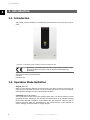
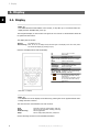
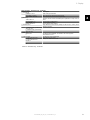
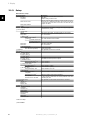
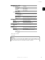
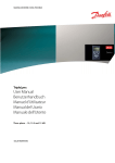
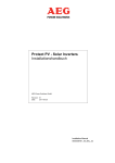
Protect PV - Solar Inverters
User Manual
AEG Power Solutions GmbH
Revision: 01
Date:
2011-05-25
User Manual
8000038784_00_BAL_en
Contents
Contents
1. Introduction
2
Introduction
2
Operation Mode Definition
2
2. Display
4
Display
4
View
5
View 2
5
Status
6
Production Log
8
Setup
10
3. Web Server Quick Guide
12
Introduction
12
Supported Characters
12
Access and Initial Setup
12
Setup Wizard
13
Operation
17
Web Server Structure
17
Plant, Group and Inverter Views
19
Additional Information
20
4. Troubleshooting
21
Troubleshooting
21
5. Maintenance
22
Maintenance
22
Cleaning the Cabinet
22
Cleaning the Heatsink
22
8000038784_00_BAL_en / L00410565-01_02
1
1. Introduction
1
1. Introduction
1.1. Introduction
This manual provides information on functionality and maintenance of the Protect PV solar inverter.
Illustration 1.1: Protect PV 10 kW, Protect PV 12.5 kW, Protect PV 15 kW
CE marking - This certifies the conformity of the equipment with the regulations which apply in accordance with the directives 2004/108/EC and
2006/95/EC.
The Protect PV inverter series comprises:
Protect PV
Protect PV easy
1.2. Operation Mode Definition
Off grid (LEDs off)
When no power has been delivered to the AC grid for more than 10 minutes, the inverter disconnects from the grid and shuts down. This is the normal night mode. The user and communication interfaces are still powered for communication purposes.
Connecting (Green LED flashing)
The inverter starts up when the PV input voltage reaches 250 V. The inverter performs a series
of internal self-tests, including PV auto detection and measurement of the resistance between
the PV arrays and earth. Meanwhile, it also monitors the grid parameters. When the grid parameters have been within the specifications for the required amount of time (depends on
country settings), the inverter starts to energise the grid.
2
8000038784_00_BAL_en / L00410565-01_02
1. Introduction
On grid (Green LED on)
The inverter is connected to the grid and energises the grid. The inverter disconnects if: It detects abnormal grid conditions (depending on country settings), if an internal event occurs or if
no PV power is available (no power is supplied to the grid for 10 minutes). It then goes into
connecting mode or off grid mode.
1
Fail Safe (Red LED flashing)
If the inverter detects an error in its circuits during the self-test (in connecting mode) or during
operation, the inverter goes into fail safe mode. The inverter will remain in fail safe mode until
PV power has been absent for a minimum of 10 minutes, or the inverter has been shut down
completely (AC + PV).
Refer to the section on Troubleshooting for further information.
8000038784_00_BAL_en / L00410565-01_02
3
2. Display
2. Display
2
2.1. Display
Note:
Due to the advanced functionalities of the inverter, it may take up to 10 seconds before the
display becomes available after power up.
The integrated display on the inverter front gives the user access to all information about the
PV system and the inverter.
The display has two modes:
Normal
Power saving
The display is in use
After 10 min. of no display activity the back light of the display turns off to save power.
Re-activate the display by pressing any key
Overview of display buttons and functionality:
F1
F2
F3
F4
* When an F-key is
up.
Home
OK
Arrow up
Arrow Down
Arrow Right
Arrow Left
Back
On - Green LED
Alarm - Red LED
View 1 / View 2 - Screen
Status Menu
Production Log Menu
Setup Menu
selected the LED above it will light
Return to View Screen
Enter/select
A step up/increase value
A step down/decrease value
Moves cursor right
Moves cursor left
Return/de-select
On/flashing = On grid/Connecting
Flashing = Fail safe
The inverter is configured as master. Icons can be found in the top
right corner.*
The inverter is connected to a master. Icons can be found in the top
right corner.*
*) Protect PV easy only.
Illustration 2.1: Display
Note:
The contrast level of the display can be altered by pressing the arrow up/down button while
holding down the F1 button.
The menu structure is divided into four main sections:
View
Status
Production Log
Setup
Presents a short list of information, read only.
Shows inverter parameter readings, read only.
Shows logged data.
Shows configurable parameters, read/write.
See the following sections for more detailed information.
4
8000038784_00_BAL_en / L00410565-01_02
2. Display
2.1.1. View
Menu Structure - View
Parameter
Mode: On grid
Prod. today: 12345 kWh
Output Power: 12345 W
[ --- utilization bar --- ]
Description
Displays present inverter mode. See operation mode definitions
Energy production today in kWh. Value from inverter or S0 energy-meter
Current output power in Watt
Shows level of inverter utilisation as % of max. utilisation
2
Table 2.1: View
2.1.2. View 2
Menu Structure - View 2
Parameter
Description
Indicates whether or not any grid management measures are in effect.
Grid mgmt:
Hidden if no grid management measures are in effect.
Performance ratio is shown if irradiation sensor is available (local or master).
Performance ratio: 87 %*
Lifetime CO2 emission saved, calculated using configured value.
Total CO2 saved:123 T*
Total revenue: 234.5 Euro * Lifetime revenue, calculated using configured value.
Table 2.2: View 2
*) Not available.
8000038784_00_BAL_en / L00410565-01_02
5
2. Display
2.1.3. Status
Menu Structure - Status
Display Functions
[-] Ambient Conditions
Irradiance: 1400W/m2
PV module temp: 100 oC
Ambient temp: 20 oC
Irr. sensor temp: 20 oC
[-] Photovoltaic
[-] Present values
[-] PV input 1
Voltage: 1000V
Current: 15.0 A
Power 10000 W
[+] PV input 2
[+] PV input 3
[-] Isolation Resistance
Resistance: 45 MΩ
[-] PV Input Energy
Total: 369000kWh
PV1: 123000 kWh
PV2: 123000 kWh
PV3: 123000 kWh
[-] PV Configuration
2
Description
Only applicable if sensors are connected
Irradiance. “NC” if not connected
PV module temperature. “NC” if not connected
Ambient temperature. “NC” if not connected
Irradiation sensor temperature. “NC” if not connected
Voltage detected at PV input 1
Current detected at PV input 1
Power detected at PV input 1
Not visible if inverter type is 10 kW
PV isolation at start up
Daily
Daily
Daily
Daily
production
production
production
production
of
of
of
of
all PV inputs
PV input 1
PV input 2
PV input 3
Configuration of PV input 1. The configuration is only shown when the inverter is in Connecting or On grid mode.
PV input 1: Individual
PV input 2: Individual
PV input 3: Individual
[-] AC-grid
[-] Present Values
[-] Phase 1
Voltage: 250 V
Current: 11.5 A
Frequency: 50 Hz
Power: 4997 W
[+] Phase 2
[+] Phase 3
[-] Residual Current Monitor
Current: 350 mA
[-] Grid management
Voltage on phase 1
Current on phase 1
Frequency on phase 1
Power on phase 1
Residual current in mA
Only visible if the inverter is set up for feed-in to medium or high voltage
grid (e.g. _MV country is the selected country)
[-] Power level adjustment
[-] Present limit: 100 %
[-] Reactive power
Setpoint type: Off
Value: -
Maximum allowed power output in % of nominal power output. “Off”
means that the power level functionality has been disabled in the inverter.
Only displayed if the current country setting is an MV country or custom,
and in Protect PV versions.
The setpoint type for Reactive Power. Off means that no internal setpoints
are used, but the inverter will accept an external setpoint.
The current value of the setpoint for reactive power, the unit depends on
the selected setpoint type.
Table 2.3: Status
6
8000038784_00_BAL_en / L00410565-01_02
2. Display
Menu Structure - Status - Continued
Display Functions
[-] Inverter
[-] Country: Germany
[-] Internal Conditions
Power module 1: 100 oC
PCB1 (AUX): 100 oC
[-] Serial no. and SW ver.
[-] Inverter
Prod- and serial number:
A0010000201
011900H2304
Software version:
MAC address:
...
[-] Control board
Part - and serial number:
C00100003111
022500H2004
Software version:
[-] Power board
Part - and serial number:
C00100004529
0023600H2104
[-] AUX board
Part - and serial number:
C0010000241
002541H2204
[-] Communication board
Part - and serial number:
C0010000201
032500H2504
Software version:
[-] Func. Safety Processor
Software version:
[-] Display
Software version:
[-] Upload status
Upload status: Off
Signal strength: 99
GSM status: None
Network:
Failed uploads: 0
Last error: 0
Last upload:
-
Description
Country setting
2
Temperature detected at the power module
Temperature detected internally
Inverter product number
Inverter serial number
Inverter software version
The MAC address of the communication board
Control board part number
Control board serial number
Control board software version
Power board part number
Power board serial number
Aux board part number
Aux board serial number
Communication board part number
Communication board serial number
Communication board software version
Functional Safety processor software version
Display software version
Current upload status
Signal strength. Should preferably be between 16-31. 99 Indicates
no signal
Current GSM network status
Network to which the modem is connected
Number of consecutive failed uploads
Last error ID, please see the GSM manual for further assistance
Time and date of last error
Time and date of last successful upload
Table 2.4: Status - Continued
8000038784_00_BAL_en / L00410565-01_02
7
2. Display
2.1.4. Production Log
Menu Structure - Production Log
Display Functions
Total production:
123456 kWh
Total operating time:
20 hours
[-] Production log
[-] This week
Monday: 37 kWh
Tuesday: 67 kWh
Wednesday: 47 kWh
Thursday: 21 kWh
Friday: 32 kWh
Saturday: 38 kWh
Sunday: 34 kWh
[-] Past 4 weeks
This week: 250 kWh
Last Week: 251 KWh
2 Weeks ago: 254 KWh
3 Weeks ago: 458 KWh
4 Weeks ago: 254 KWh
[-] This year
January: 1000 kWh
February: 1252 KWh
March: 1254 KWh
April: 1654 KWh
May: 1584 KWh
June: 1587 KWh
July: 1687 KWh
August: 1685 KWh
September: 1587 KWh
October: 1698 KWh
November: 1247 KWh
December: 1247 KWh
[-] Past years
This year: 10000 kWh
Last year: 10000 kWh/m2
2 years ago: 10000 kWh/m2
3 years ago: 10000 kWh/m2
...
20 years ago: 10000 kWh/m2
[-] Irradiation log
[-] This week
Monday: 37 kWh/m2
Tuesday: 45 kWh/m2
Wednesday: 79 kWh/m2
Thursday: 65 kWh/m2
Friday: 88 kWh/m2
Saturday: 76 kWh/m2
Sunday: 77 kWh/m2
[-] Past 4 weeks
This week: 250 kWh/m2
Last week: 320 kWh/m2
2 weeks ago: 450 kWh/m2
3 weeks ago: 421 kWh/m2
4 weeks ago: 483 kWh/m2
[-] This year
January: 1000 kWh/m2
February: 1000 kWh/m2
March: 1000 kWh/m2
April: 1000 kWh/m2
May: 1000 kWh/m2
June: 1000 kWh/m2
July: 1000 kWh/m2
August: 1000 kWh/m2
September: 1000 kWh/m2
October: 1000 kWh/m2
November: 1000 kWh/m2
December: 1000 kWh/m2
[- ] Past years
This year: 10000 kWh/m2
Last year: 10000 kWh/m2
2 years ago: 10000 kWh/m2
3 years ago: 10000 kWh/m2
...
20 years ago: 10000 kWh/m2
2
Description
Total production since installation of inverter
Total operating time since installation of inverter
Production from this week
Production from one day shown in KWh
Production from this week shown in KWh
Production from one month shown in kWh
Yearly production, up to 20 years back
Production from this year shown in KWh
Only visible if it contains non-zero values
Irradiation from this week
Irradiation from one day shown in kWh/m2
Irradiation from this week shown in kWh/m2
Irradiation from one month shown in kWh/m2
Yearly irradiation up to 20 years back are shown
Table 2.5: Production Log
8
8000038784_00_BAL_en / L00410565-01_02
2. Display
Menu Structure - Production Log - Continued
Display Functions
Description
[-] Time stamps
Installed: 31-12-07
Date of first grid connection
Power down: 21:00:00
When the inverter was last connected to grid
Prod. initiated: 06:00:00
When the inverter first connected to grid today
[-] De-rating
Period of time the inverter has limited power production in total, shown in
Total de-rate: 0 h
hours
Pwr level adjust: 0 h
Due to Power level adjustment
Freq. stabiliza.: 0 h
Due to frequency support
Reactive Power: 0 h
Due to reactive energy support
[-] Reactive Power
Only visible if the current country setting is an MV country or custom, and in
Protect PV versions.
[-] Reactive Energy (underexcited):
1000 000 VArh
[-] Reactive Energy (overexcited):
1000 000 VArh
[-] Event log
Latest event:
The latest event is displayed. The number is for service purposes
0
Zero indicates no error.
[-] Last 20 events
The latest 20 events are displayed
1 : 29-01-2009 14:33:28
Date and time of the event
Grid 29 off
Group - ID - Status of the event
2 : 29-01-2009 14:33:27
Grid 29 on
20:
2
Table 2.6: Production Log - Continued
8000038784_00_BAL_en / L00410565-01_02
9
2. Display
2.1.5. Setup
Menu Structure - Setup
Display Functions
[-] External Alarm
Stop Alarm
Test Alarm
2
Description
Only applicable if external alarm is connected
Stop alarm
Includes testing red LED on front
Amount of time the alarm is active in seconds. If value is set to 0,
alarm time-out is disabled and the alarm will be active until the failure that has triggered the alarm is corrected or the alarm has been
stopped. See above.
Alarm time-out: 009 s
Alarm state: Disabled
[-] Setup details
The language in the display; changing the display language does
not affect country setting
Language: English
[-] Inverter details
Inverter name:
AEG PS
Group name:*
Group name
[-] Master mode*
Master mode: Enabled*
[-] Network*
[-] Initiate network scan
[-] Scan progress: 0%
[-] Inverters found: 0
Plant name:*
*
Plant name
[-] Set date and time
Date: dd.mm.yyyy (30.12.2002)
Time: hh.mm.ss (13.45.27)
[-] Calibration
[-] PV array
PV input 1: 6000 W
PV 1 area: 123 m2
PV input 2: 6000 W
PV 2 area: 123 m2
PV input 3: 6000 W
PV 3 area: 123 m2
[-] Irradiation sensor
Scale (mV/1000 W/m2): 75
Temp. coeff: 0.06 %/oC
[-] Temp. sensor offset
PV module temp: 2 oC
Ambient Temp: 2oC
[-] S0 sensor input
Scale (pulses/kWh): 1000
[-] Environment
CO2 emission factor:*
0.5 kg/kWh*
Remuneration per kWh:*
44.42 ct/kWh
Yield start count: 1000 kWh*
[-] Communication setup
[-] RS485 setup
Network: 15
Subnet:15
Address: 255
[-] IP Setup
IP config: Automatic
IP address:
192.168.1.191
Subnet mask:
255.255.255.0
Default gateway:
192.168.1.1
DNS server:
123.123.123.123
The inverter's name. Max. 15 characters and not only numbers.
The name of the group the inverter is part of
Max. 15 characters
Only visible if Master mode is enabled.
The name of the plant.
Max. 15 characters
Set the current date
Set the current time
Only applicable if sensors are connected
Not visible if inverter only has 2 PV inputs
Not visible if inverter only has 2 PV inputs
Sensor calibration
Sensor calibration
Sensor calibration (offset)
Sensor calibration (offset)
Sensor calibration. See note
Value to be used for total CO2 saved calculation
Value to be used for total revenue calculation
A value used as an offset from the current production value when
calculating the yield.
Only applicable if communication accessories are connected
Table 2.7: Setup
*) Not available.
10
8000038784_00_BAL_en / L00410565-01_02
2. Display
Menu Structure - Setup - Continued
Display Functions
GPRS connection setup
SIM PIN code: 0000
Access point name:
name
User name:
user
Password:
password
Roaming: Disabled
[-] Data warehouse service
Upload channel: LAN
Upload time (h:m): 14:55
Start log upload
D.W FTP server address:
www.inverterdata.com
D.W server port: 65535
FTP mode: Active
D.W. server user name:
User
D.W server password
Password
[-] Autotest
Status: Off
Ugrid: 234 V
Utest: 234 V
Fgrid: 50.03 Hz
Ftest: 50.03 Hz
Disconnection time: 53 ms
[-] Logging
Interval: 10 min*
Logging capacity:
10 Days
[-] Web Server
Reset password
[-] Security
Password: 0000
Security level: 0
Log out
[-] Service logon
User name:
user name
Password:
password
Description
4-8 characters
Max. 24 characters
2
Max. 24 characters
Max. 24 characters
Requires data from at least 10 min. of energy production
Default serial number of the inverter
User name for Data warehouse account, max. 20 chars.
Password for Data warehouse account, max 20 chars.
Initiate autotest, only applicable with country setting; Italy
Only visible during voltage tests
Only visible during voltage tests
Only visible during frequency tests
Only visible during frequency tests
Not visible in Off and Completed OK states
The interval between each logging
Resets the password of the Web Server to its default value
Level of access to inverter parameters and settings
Current security level
Log out to security level 0
Only to be used by authorised service personnel
Table 2.8: Setup - Continued
*) Not available.
Note:
When a value is set in the S0 energy meter calibration menu the inverter disables its own
energy counter in order to show the value from the S0 meter. Therefore the energy count
will not be shown if a value is set, even though no S0 meter is connected.
8000038784_00_BAL_en / L00410565-01_02
11
3. Web Server Quick Guide
3. Web Server Quick Guide
3.1. Introduction
3
These instructions describe the Protect PV Web Server, which facilitates remote access to the
inverter.
Refer to the download area at www.aegps.com/solarinverters for the newest instructions.
3.2. Supported Characters
In all language versions, the following characters are supported and can be entered via the
Web Server:
Letters
abcdefghijklmnopqrstuvwxyz
Capital letters
ABCDEFGHIJKLMNOPQRSTUVWXYZ
Numbers
0123456789
Special characters .,-+?!@:;/\_()#* %
Note! No spaces are allowed in inverter name.
For plant, group and inverter name, only the following characters are supported:
Letters
abcdefghijklmnopqrstuvwxyz
Capital letters
ABCDEFGHIJKLMNOPQRSTUVWXYZ
Numbers
0123456789
Special characters - _.
Note! No spaces are allowed in inverter name.
3.3. Access and Initial Setup
3.3.1. Access via PC Ethernet Interface
Change the Web Server logon and password of the master inverter immediately
for optimal security when connecting to the internet. To change the password go
to [Setup → Web Server → Admin].
Setup Sequence:
12
1.
Select which inverter will be set up as master.
2.
Open the cover of this inverter. Refer to the Protect PV Installation Manual for instructions.
3.
Connect the inverter RJ45 interface to the PC Ethernet interface using a patch cable
(network cable cat5e, crossed or straight through).
4.
On the PC, wait until Windows reports limited connectivity (if no DHCP is present).
Then open the internet browser.
5.
Type http://invertername in the address field:
•
Find the serial number on the product label, located on the side of the housing.
•
'Invertername' is the final 10 digits of the serial number (1).
8000038784_00_BAL_en / L00410565-01_02
3. Web Server Quick Guide
3
Illustration 3.1: Product Label
6.
The Web Server logon dialog opens.
7.
Type 'admin' in the user and password fields, and click [Log in].
8.
At initial logon the inverter runs a setup wizard. Ensure pop-ups are enabled before
the wizard starts.
3.3.2. Setup Wizard
Step 1 of 7: Master setting
To set up a master inverter, click on [Set this inverter as master].
•
A scan runs to identify inverters in the network.
•
A pop-up window shows the inverters successfully identified.
Click [ok] to confirm that the correct number of inverters has been found.
Illustration 3.2: Step 1 of 7: Master Setting
To change this setting later, refer to Setup, Inverter Details.
Step 2 of 7: Display language
Select display language. This is not a country setting.
•
The default language is English.
8000038784_00_BAL_en / L00410565-01_02
13
3. Web Server Quick Guide
3
Illustration 3.3: Step 2 of 7: Display Language
To change the language setting later, refer to Setup, Setup Details.
Step 3 of 7: Time and date
Enter
•
time in 24-hour format
•
date
•
time zone
Accuracy is important, because date and time are used for logging purposes. Adjustment for
daylight savings is automatic.
Illustration 3.4: Step 3 of 7: Time and Date
To change these settings later, refer to Setup, Inverter details, Set Date and Time.
Step 4 of 7: Installed power
For each PV input, enter
•
surface area
•
installed power
For more information refer to the Protect PV Reference Manual.
14
8000038784_00_BAL_en / L00410565-01_02
3. Web Server Quick Guide
Incorrect setting can have serious consequences for production efficiency.
3
Illustration 3.5: Step 4 of 7: Installed Power
To change the installed power, refer to Setup, Calibration, PV Array.
Step 5 of 7: Country setting
Select the country setting to match the installation. To meet medium voltage grid requirements
select a country option ending in MV.
•
The default setting is [undefined].
Select the country setting again, to confirm.
•
The setting is activated immediately.
Correct selection is essential to comply with local and national standards.
An incorrect setting can have serious consequences.
8000038784_00_BAL_en / L00410565-01_02
15
3. Web Server Quick Guide
3
Illustration 3.6: Step 5 of 7: Country Setting
Note:
If the initial and confirmation settings are different,
•
country selection is cancelled
•
the wizard recommences step 5
If initial and confirmation settings match, but are incorrect, contact service.
To change the country setting later, refer to Setup, Setup Details.
Step 6 of 7: Replication
To replicate the settings from steps 1 to 6 to other inverters in the same network
•
Select inverters
•
Click [Replicate]
Note:
When the PV configuration, installed PV power and PV array area of follower inverters in the
network differ from that of the master, do not replicate. Set up the follower inverters individually.
16
8000038784_00_BAL_en / L00410565-01_02
3. Web Server Quick Guide
3
Illustration 3.7: Step 6 of 7: Replication
Step 7 of 7: Inverter startup
The inverter will start automatically when the installation sequence is complete (see the Protect
PV Installation Manual), and solar radiation is sufficient.
The startup sequence, including self-test, takes a few minutes.
Illustration 3.8: Step 7 of 7: Inverter startup
To change the setup later, access the inverter via the integrated web interface or the display, at
inverter level.
•
To change the name of the inverter, go to [Setup → Inverter details]
•
To enable master mode, go to [Setup → Inverter details]
3.4. Operation
3.4.1. Web Server Structure
The Web Server overview is structured as follows.
8000038784_00_BAL_en / L00410565-01_02
17
3. Web Server Quick Guide
3
Illustration 3.9: Overview
1.
2.
3.
Plant name: Displays the current plant name:
•
Click on the plant name to display the plant view.
•
Change the plant name at [Setup → Plant details].
Group menu: Displays groups of inverters:
•
Inverters join group 1 by default
•
Click on a group name to display the group view, and a list of inverters in the
group.
•
Change the group name via [Setup → Inverter details] in the inverter view.
Group members: Displays the inverter names in the group currently selected. The
default inverter name is based on the serial number (see section Accessing the Web
Server):
•
Click on an inverter name to display the inverter view.
•
Change the name of the inverter via [Setup → Inverter details] in the inverter
view.
4.
Main menu: This menu corresponds to the inverter display main menu.
5.
Sub menu: The sub menu corresponds to the main menu item currently selected. All
sub menu items belonging to a particular main menu item are displayed here.
6.
Content area: The Web Server main menu and sub menus are identical to the menus
in the inverter display. The sub menu content displayed here corresponds to the sub
menu selected: [Overview]. On some pages, a horizontal menu provided for improved
readability.
7.
Footer: Options on the footer bar:
•
18
Language: Opens a pop-up window. Click on the country flag to change the
language of the Web Server to the desired language for the active session.
8000038784_00_BAL_en / L00410565-01_02
3. Web Server Quick Guide
•
Contact: Opens a pop-up window which displays AEG PS contact information.
•
Logout: Opens the log in / log out dialog box.
•
Security level: Displays the current security level as explained in the section
Security Levels.
3
Note:
The content of the main menu changes depending on which view is currently selected: the
plant, a group of inverters or an individual inverter. The active view is indicated by text in
red.
3.4.2. Plant, Group and Inverter Views
The overview screens for plant view, group view, and inverter view display the same overall
status information.
Illustration 3.10: Plant View
8000038784_00_BAL_en / L00410565-01_02
19
3. Web Server Quick Guide
Item
Unit
Overall plant status
-
View
Plant
and
Group
x
Description
Inverter
3
x
Current production
Yield today
Total revenue
Total CO2 saving
Performance ratio
Total yield
Power limit adjustment
kW
kWh
Euro
kg
%
kWh
%
x
x
x
x
x
x
x
x
x
x
x
x
x
Red: Plant PR <50%, or:
Any inverter in the network
- in fail safe mode, or
- missing from the scan list, no contact with the master
Yellow: Any inverter in the network
- with PR<70%, or
- in Connecting or Off grid mode
Green: Plant PR ≥ 70%, and
- all inverters with PR≥ 70%, and
- all inverters in On grid mode
Red: Inverter PR<50%, or inverter has an error
Yellow: Inverter PR between 51% and 70%, or inverter
in Connecting mode
Green: No errors, and
- inverter PR≥70%, and
- inverter in "on grid" mode
Real time energy production level
Cumulative yield for the day
Cumulative revenue earned since initial startup
Cumulative CO2 saved since initial startup
Real time performance ratio
Cumulative yield since initial startup
Maximum power limit as % of nominal inverter AC output
rating
Note:
To calculate performance ratio PR, an irradiation sensor is required, see [Setup → Calibration].
3.5. Additional Information
Refer to the Web Server User Manual to learn more about:
20
•
Inverter start-up and check of settings
•
Messaging
•
Graphs
•
Remote access
•
Web portal upload
•
Logging capacity and changing the logging interval
•
Settings backup and restore
8000038784_00_BAL_en / L00410565-01_02
4. Troubleshooting
4. Troubleshooting
4.1. Troubleshooting
Only trained and authorised personnel familiar with electrical systems and safety
issues may work on inverters and electrical installations.
4
Should the inverter not supply energy as expected, go through the checklist before calling service.
1.
Check that the grid is properly connected to the inverter and that the mains switch is
not switched off.
2.
Check that there is sufficient solar radiation to generate power. UPV >250 V
3.
Check for shading and loose cables/connections in the PV system.
4.
Check whether the voltage of the PV modules are within the expected values. If not go
to point 7.
5.
Check whether the voltage values of the grid lie within the threshold values. If this is
not the case please contact your public utility for technical assistance.
6.
If the above-mentioned points are OK, wait 15 minutes to find out whether there is a
permanent failure.
7.
If the PV system still supplies no power to the grid, check the display for:
-
PV module voltage, current and power
-
grid voltage, current and power
-
event text, see log area
Then call service.
In the event of a failure, the red LED will flash and the display will show an event. Refer to the
table for event descriptions and recommended actions.
Event text
Grid
Description
Grid values are out of range
PV
Internal
The PV isolation resistance is too
low
An internal event has occurred
Fail Safe
Internal or AC installation error
Remedy
Check the voltage and frequency values in the display. If values
are zero, check the circuit-breaker (fuses) and cables. If values
are outside the applied limits, request technical service from installer/energy company.
Make a visual inspection of all PV cables and modules. If the event
occurs frequently, request technical service.
Make sure airflow over the heat sink is not obstructed. Wait 5 minutes. If the inverter does not reconnect (although sufficient irradiance is available) or the event occurs regularly, action must be
taken. Service inverter.
Turn off both AC and DC (PV) power to the inverter. Make a visual
inspection of the PV installation, if everything is in order, wait 5
minutes and re-apply AC and DC (PV) power. If the inverter resumes fail safe operation, action must be taken. Service inverter.
Table 4.1: Events
Note:
For more event descriptions, refer to the Protect PV Reference Manual in the download area
at: www.aegps.com/solarinverters
8000038784_00_BAL_en / L00410565-01_02
21
5. Maintenance
5. Maintenance
5.1. Maintenance
Normally, the inverter needs no maintenance or calibration.
Ensure the heatsink at the rear of the inverter is not covered.
5
Clean the contacts of the PV load switch once per year. Perform cleaning by cycling the switch
to on and off positions ten times.The PV load switch is located at the base of the inverter.
5.1.1. Cleaning the Cabinet
Clean the inverter cabinet using pressurised air, a soft cloth or a brush.
5.1.2. Cleaning the Heatsink
Clean the heatsink using pressurised air, a soft cloth or a brush.
For correct operation and long service life, ensure free air circulation
-
around the heatsink at the rear of the inverter
-
to the fan at the inverter base
Do not touch the heatsink during operation.
Temperature can exceed 70°C.
Note:
Do not cover the inverter.
Do not use a water hose, aggressive chemicals, cleaning solvents or strong detergents to
clean the inverter.
22
8000038784_00_BAL_en / L00410565-01_02
France & Africa
Italy
Czech Republic
AEG Power Solutions
ZI 10 rue Jean Perrin
37173 Chambray-lès-Tours
Tel:
+ 332 47 80 88 96
Fax:
+ 332 47 80 88 38
[email protected]
Email:
AEG Power Solutions
Via Trento 30
20059 Vimercate – Milan
Tél :
+39 0 39 686 3837
Fax :
+39 0 39 686 3847
[email protected]
Email:
AEG Power Solutions spol. s r.o.
Na vlastní pude 6/1368
102 00 PRAHA 15 Hostivar
Tel:
+ 420 602 316 314
Fax:
+ 420 274 773 265
Email:
[email protected]
Germany
Spain
Netherlands
AEG Power Solutions
Emil-SiepmannStr.32
D-59581 Warstein/Belecke
Tel:
+ 49 2902 763 100
Fax:
+ 49 2902 763 645
Email: [email protected]
AEG Power Solutions, SL
Parque Tecnologico de Alava
C/Albert Einstein 31
01510 Minano – Alava
Tél:
+ 34 66 990 31 12
Fax:
+34 945 21 41 11
Email: [email protected]
AEG Power Solutions
Weerenweg 29
1161 AH Zwanenburg
Tel:
+ 31 20 40 77 818 / 821
Tel.outside office hours
+ 31 20 40 77 866
Fax:
+ 31 20 40 77 801
Email: [email protected]
United Kingdom
AEG Power Solutions Ltd.
Vision 25
Innova Park
Enfield EN3 7XY
Tel:
+44 (0) 1992 719 200
Fax:
+44 (0) 1992 702 151
[email protected]
Email:
Lit. No. L00410565-01_02 Rev. date 2011-05-25