1
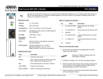
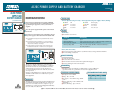
JOBAID
AC/DC POWER SUPPLY AND BATTERY CHARGER
61175044L2-22A
0002
AC/DC POWER
SUPPLY AND
BATTERY CHARGER
MOUNTING INSTRUCTIONS
STATUS LEDS
Remove the TA 750/850 AC Power Supply (ADTRAN
part # 1175043LX) from the box and inspect for damage. If damage is apparent, contact your carrier or
supplier.
AC Power Operation (AC power only)
● GREEN
OK
● YELLOW
Power Fail
● RED
Power Fail
● OFF
Power Fail
Place the power supply with the power cord oriented
RELAYS
CLEI:SIMPAAAARA
1
2 downward.
3
Use four #6 x 3/8" machine screws (supplied) to mount
the power supply to either side of the TA 750/850 shelf.
Battery Operation (AC power supply or battery backup)
● GREEN
OK (charging)
● YELLOW
Discharging
● RED
Low (<40 V)
● OFF
Disconnected
Alarm Relay
■ Provided for customer use
Note: Threaded mounting holes are provided on both sides of
the shelf.
Note: For battery backup installations, it is recommended to
mount the power supply on the left side of the TA 750/850
shelf, next to the battery cover hinge.
Note: Alternatively, the power supply can be mounted to the
backboard with four #6 x 1" wood screws (not supplied).
Condition
Alarm Relay
Normal
Open
AC Power Failure/
Battery Backup engaged
Cycles open/closed once per second if AC voltage <88 Vrms at
full load and battery backup is connected
Battery voltage <45V
Stays closed if voltage <45 VDC to indicate that battery is
becoming depleted
Battery Disconnect Relay
■ Disconnects battery pack from the system if the battery voltage falls below 40 VDC
■ Prevents damage to batteries
CIRCUIT BREAKER
3-amp circuit breaker
Protects unit from over-current
■ Rocker button extends out from front panel when tripped
■ Reset by pushing in on the rocker button
■
■
The device complies with Part 15 of the FCC rules.
Operation is subject to the following two conditions:
(1) This device may not cause harmful interference,
and (2) this device must accept any interference
received, including interference that may cause undesired operation.
Changes or modifications not expressly approved by
ADTRAN could void the user’s authority to operate
this equipment.
GROUNDING
■
ELECTRICAL SPECIFICATIONS
AC input: 115 V nominal
Range: 90 to 132 VAC
■ DC output: -54 V, 60 W average, 100 W
peak
■ Battery charging: 16 hr nominal, 24 hr
maximum
■ Battery discharge: Up to 8 hours
■
■
WARRANTY
C A U T I O N !
SUBJECT TO ELECTROSTATIC DAMAGE
OR DECREASE IN RELIABILITY.
HANDLING PRECAUTIONS REQUIRED.
Warranty for Carrier Network products manufactured
by ADTRAN and supplied under Buyer’s order for use
in the U.S. is ten (10) years. For a complete copy of
ADTRAN’s U.S. Carrier Network Equipment Warranty:
(877) 457-5007, Document 414.
■
18 AWG or larger ground wire recommended to connect additional
ground connector to 'ground bus' in customer equipment room
TELECOMMUNICATIONS CODES
Code
IC
TC
PC
For a complete I&M Practice: 877.457.5007, Document # 422. Please have fax number available. ■
Input
F
—
R
Output
C
—
—
JOBAID
BACKUP BATTERY PACK
BACKUP
MOUNTING INSTRUCTIONS
BATTERY
the TA 750/850 Battery Backup system and
PACK 1 Unpack
inspect for damage. If damage is apparent, refer to
your carrier or supplier for remedy.
CLEI:SIMPBBBARA
Note: It is not necessary to remove the batteries during
installation process.
battery box must be mounted with the following
2 The
minimum clearances:
Top – 9"
Bottom – 5"
Left Side – 5"
Right Side – 2"
Life expectancy: 3-5 years on standby use
Battery performance is adversely affected by extreme temperatures.
■ Old batteries should be recycled.
■
■
BATTERY SPECIFICATIONS
Batteries: 7 Amp/hr (4 batteries per pack)
Case size: 6”W x 3 3/4”H x 2 1/2”D
■ Battery type: Lead acid
■ Voltage: -54 VDC
■ Backup Time: Up to 8 hours
■ Wire Gauge: 18 AWG
■ Preferred Temperature: 68º F (20º C)
■
Insert #10 x 3/4" flat-head wood screws (supplied)
into the three pilot holes, leaving 1/16" space
between the screw-head and the backboard.
CAUTION: Fully loaded Battery box weighs 30 lbs.
5
MAINTENANCE
■
the template provided, mark and drill three
3 Using
pilot holes for #10 mounting screws.
4
PRICING AND AVAILABILITY 800.827.0807
TECHNICAL SUPPORT 888.4ADTRAN
RETURN FOR REPAIR 256.963.8722
Mount the battery box on the three support screws
on the backboard.
the two closure screws on the battery box
6 Remove
and open the cover.
a long shaft screwdriver to tighten the three
7 Use
support screws.
The device complies with Part 15 of the FCC
rules. Operation is subject to the following
two conditions: (1) This device may not
cause harmful interference, and (2) this
device must accept any interference
received, including interference that may
cause undesired operation.
Changes or modifications not expressly
approved by ADTRAN could void the user’s
authority to operate this equipment.
TA 750
R1-I
T1-I
R-O
T-O
Input
—
—
E
DC
POWER
CAUTION
During TA 750 wall
installation, position
the chassis so front
panels face up.
LX OUT
LY OUT
EU1
MLT-A
-48 R
MLT-B
-48ALM
MJ
MJR
-48 V
MJV
MJVR
MANAGEMENT
TELECOMMUNICATIONS CODES
Code
IC
TC
PC
Terminal P2
LX IN
access
LY IN
coverEU2
T1
FT1
Warranty for Carrier Network products manufactured
by ADTRAN and supplied under Buyer’s order for use
in the U.S. is ten (10) years, except for batteries which
carry manufacturer’s warranty. For a complete copy of
ADTRAN’s U.S. Carrier Network Equipment Warranty:
(877) 457-5007, Document 414.
-54 VDC Output to TA 750
AC/DC Power Supply
Battery Charging Unit
P/N: 1175043LX
Output
C
—
—
1175044L2
BATTERY BACKUP
V.35
WARNING:
20 Hz FUSE
MUST BE REMOVED
BEFORE REMOVING COVER.
WARRANTY
-48 VDC Backup Battery Pack
To Alarms
120VAC/
2A 60HZ INPUT
-54VDC
OUTPUT
BATTERY
INPUT
GROUND
AC Power Input
C A U T I O N !
SUBJECT TO ELECTROSTATIC DAMAGE
OR DECREASE IN RELIABILITY.
HANDLING PRECAUTIONS REQUIRED.
■
For a complete I&M Practice: 877.457.5007, Document # 423. Please have fax number available. ■
+
AC ALARM
OUTPUT
-
-54 VDC Battery
Charging/Discharging Line