1
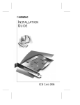
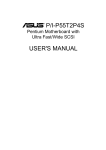
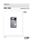
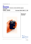
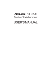
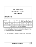
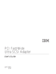
PCM-3420
PC/104 Fast SCSI-2 Module
Copyright Notice
This document is copyrighted, 1997. All rights are reserved. The
original manufacturer reserves the right to make improvements to the
products described in this manual at any time without notice.
No part of this manual may be reproduced , copied , translated or
transmitted in any form or by any means without the prior written
permission of the original manufacturer. Information provided in this
manual is intended to be accurate and reliable . However, the original
manufacturer assumes no responsibility for its use , nor for any
infringements upon the rights of third parties which may result from
its use.
Acknowledgements
Adaptec , Adaptec logo, AHA, and EZ-SCSI are trademarks of
Adaptec Inc.
PC/104 and the PC/104 logo are registered trademarks of the PC/104
Consortium
Floptical is a trademark of Insite Peripherals
Windows and Windows 95 are registered trademarks of Microsoft
Corporation
Windows NT is a trademark of Microsoft Corporation
IBM, AT, OS/2 and Micro Channel are registered trademarks of
International Business Machines Corporation
Microsoft, MS-DOS, and MS are registered trademarks of Microsoft
Corporation
Novell and Netware are registered trademarks of Novell, Inc.
SCO is a registered trademark of The Santa Cruz operation, Inc.
UNIX is a registered trademark; and USL is a trademark of UNIX
system Laboratories.
All other product names or trademarks are properties of their respective owners.
2007342000 Manual PCM-3420 Rev.A1 1st Ed.
Printed in Taiwan March 1997
Packing Set
Before you begin installing PCM-3420 Module, please make sure that
the following materials have been shipped :
- 1 PCM-3420 Fast SCSI-2 Host Adapter Module
- SCSI-2 Flat Cable (50 Pin)
- 1 PCM-3420 User's Manual
- 1 EZ-SCSI LITE utility disk for Windows
- 1 Manager Set utility disk for OS/2, Windows NT, Windows 95, and
Netware v3.1x, v4.xx
- 1 Manager Set utility disk for SCO and Unixware
- 1 Adaptec 6000 Family Manager Set User’s Guide (postscript print
files) disk
If any of these items are missing or damaged, contact your distributor
or sales representative immediately.
Contents
Chapter 1 General Information ............. 1
Product Highlights ................................................................ 2
Introduction ........................................................................... 2
Features ................................................................................. 3
Peripheral Device Support .................................................. 3
Specifications ........................................................................ 4
Technical Specifications ........................................................... 4
Physical and Environmental Specifications .............................. 4
Board layout ........................................................................... 5
Chapter 2 Hardware Installation ............ 7
Jumpers and connectors ..................................................... 8
Locating jumpers .................................................................. 9
Locating connectors ........................................................... 10
Setting jumpers ................................................................... 11
Safety precautions ............................................................... 12
Installing PCM-3420 Module ........................................... 12
Factory default settings ........................................................... 12
Jumper configuration reference .............................................. 13
SCSI hard disk drive connecting ...................................... 18
Chapter 3 EZ-SCSI Quick Reference...... 19
System requirements .......................................................... 20
Quick start instructions ..................................................... 20
Windows 95 or Windows NT ..................................................20
Windows/Windows for Workgroups 3.1x ................................ 21
DOS ........................................................................................21
Troubleshooting Tips ......................................................... 22
SCSI Device Troubleshooting ............................................... 22
Windows 95/Windows NT Troubleshooting .......................... 22
Information for DOS/Windows 3.1x users ...................... 26
Appendix A Installing PC/104 Modules 31
Appendix B Pin Assignments ............... 35
PC/104 connectors .................................................................. 36
SCSI Hard Drive Connector ...................................................37
Appendix C Glossary of Technical Terms39
CHAPTER
General
Information
1
This chapter gives background information on the PCM-3420.
You can find out :
l
Product Highlights
l
Product Features
l
Compatibility
l
Product Specifications
l
Card Layout
Chapter 1 General Information
1
Product Highlights
l
PC/104 Embedded-PC Module
l
SCSI-2 Compatibility
l
Optimized performance for DOS and Windows; support for all major
operating systems
l
Customer configuration to match specific requirements
l
Economical connection of up to seven(7) SCSI devices
l
Proven Adaptec quality and reliability
Introduction
The PCM-3420 host adapter offers a wide range of flexible, economical
and expandable solutions that can satisfy diverse needs in SCSI
connectivity. Based on Adpatec’s proven AIC-6360 protocol chip, the
PCM-3420 supports all major operating systems - DOS, Windows,
Windows NT, Netware, UNIX, and OS/2 that permit precise matching
of products to specific requirements, and allows rapid system-level
configurations.
The PCM-3420 is particularly well suited to easy, inexpensive connection of CD-ROM drivers as well as ideal for connecting a stack of
seven different SCSI peripheral - from hard disks and CD-ROM drives
to tape, DAT and removable-media drives.
Supporting Fast SCSI, with transfer speeds of 10 Mbytes/sec, PCM3420 also provides advanced features such as synchronous and
asynchronous data transfer, support for multitasking and full DMA
support.
Whatever the particular configuration, each of the PCM-3420 host
adapter can be relied on for the high levels of quality, compatibility and
reliability.
2
PCM-3420 User's Manual
Features
l
Adaptec’s proven AIC-6360 16-bit fast SCSI protocol chip.
l
Fully Adaptec AHA-1520A hardware compatible.
l
Fully Adaptec AHA-1510A/1520A/1522A software compatible.
l
SCSI-2 and Fast SCSI-2 devices are supported.
l
ASW SCSI BIOS provided, which supports boot capability.
l
Synchronous and Asynchronous data transfer modes are supported.
l
128 Bytes FIFO to speed up the data transfer rate to 10MB/sec.
l
Complete software drivers and utilities included.
l
I/O configuration by jumpers.
l
Active termination, easy to setting by JP2.
l
Line busy status LED indicator.
l
Single power supply: +5V.
Peripheral Device Support
l
l
l
l
l
l
l
l
l
Hard Disk Drivers: Conner, Fujitsu, Hewlett-Packard, Hitachi, IBM, Maxtor,
Micropolis, Quantum, Segate.
QIC Tape Drivers: Archive, Cipher, Sankyo, Tallgrass, Tandberg, Teac,
Tecmar, Wangtek.
DAT Drivers: Archive, Exabyte, Gigatrend, Hewlett-Packard, JVC, Maynard,
R-Byte, Sony, Tecmar, WangDat, Wangtek.
CD-ROM Drivers: Chinon, Denon, Hitachi, IBM, LMSI, NEC, Panasonic,
Pioneer, Sony, Texel, Toshiba, Goldstar.
Floptical Drivers: Insite, Iomega.
WORM Drivers: ATG, Cherokee, ISI, Kodak, LMS I, Maxtor, Mitsubishi,
Panasonic, Pioneer, Richo, Sony, Toshiba.
Magneto-Optical Drivers: Cannon, Hewlett-Packard, IBM, Matsushita,
Maxoptix, Mitsubishi, Most, Panasonic, Ricoh, Sharp, Sony.
Removable Media Drivers: Iomega, Ricoh, SyQuest, SyDOS.
JukeBoxes: Hewlett-Packard, Panasonic, LMSI.
Chapter 1 General Information
3
l
Scanners: Cannon, Hewlett-Packard, Panasonic, Ricoh.
The PCM-3420 is designed to be compatible with devices that comply with
SCSI-2 standard, including those not on this list. Not all models from a given
manufacturer have been tested.
Specifications
Technical Specifications
Computer BUS: PC/104 (ISA) Standard
Interface Protocol: PIO
Device Protocol: SCSI-2
Fast SCSI Transfer Rate: Up to 10.0 Mbytes/sec
Floppy Drive Support: None
Advanced SCSI Features:
Advanced SCSI Programming Interface(APSI) compliant
- Disconnect/reconnect
- Synchronous and Asynchronous data transfer
Electrical Terminations : Single-ended, Active
Bus Width: 16-bit
Physical and Environmental Specifications
Length: 3.6 inches
Width: 3.8 inches
Connector: 50-pin , flat cable
Operating Temperature: 32 to 140 F (0º to 60 ºC)
Humidity (operating): 5% to 95%, Non-Condensing
Power Requirements: 5.25V to 4.75V tolerance on power supply
4
PCM-3420 User's Manual
Board layout
AIC-6360
Chapter 1 General Information
5
6
PCM-3420 User's Manual
CHAPTER
Hardware
Installation
2
This chapter tells how to set up the PCM3420 hardware , including instructions on
setting jumpers and connecting SCSI
devices.
Be sure to read all the safety precautions
before you begin the installation procedure.
Chapter 2 Hardware Installation 7
Jumpers and Connectors
Connectors on the board link it to SCSI devices and other PC/104
modules. In addition, the board has a number of jumpers that allow
you to configure the SCSI application to suit your systems.
The table below lists the function of each board jumpers and connectors:
Jumpers
Label
Function
JP1
LED Indicator Location
JP2
Termination Select
JP3
Set DMA Channel Select
JP4
Set IRQ Channel Select
JP5
Checking
Set PCM-3420 SCSI ID, IRQ, DMA, Parity
JP6
Set PCM-3420 Operation Mode
JP7
Set Port Address
JP8
Set PCM-3420 BIOS Address
JP9
Set PCM-3420 BIOS Address
JP10
Set PCM-3420 BIOS Function
Connectors
8
Label
Function
J1
PC/104 ISA-bus expansion
J2
PC/104 ISA-bus expansion
PCM-3420 User's Manual
CN1
JP6
Operation
Mode
JP1
LED
JP7
Port
Addr.
JP2
Termination
Select
SCSI-2 CN1
AIC-6360
JP8
BIOS
Addr.
SCSI-2 connector
JP9
BIOS
Addr.
JP10
BIOS
Func.
JP4
IRQ
Channel
JP5
SCSI ID,DMA
IRQ, Parity
JP3
DMA
Channel
PC/104 J1,J2
Chapter 2 Hardware Installation 9
Locating Jumpers & Connectors
Setting Jumpers
You configure your PCM-3420 card to match the needs of your
application by setting jumpers. Jumpers are the simplest kind of
electric switch. They consist of two metal pins and a small metal clip
(often protected by a plastic cover) that slides over the pins to
connect them. To close” a jumper you connect the pins with the clip.
To open a jumper you remove the clip. Sometimes a jumper will have
3 connect either
three pins, labeled 1, 2, and 3. In this case you would
2
1
pins 1 and 2 or 2 and 3.
Open
Closed
Closed 2-3
23
The jumper settings are schematically depicted as1 follows:
Open
Closed
Closed 2-3
A pair of needle-nose pliers may be helpful when working with
jumpers.
If you have any doubts about the best hardware configuration for
your PCM-3420 application, contact your local distributor or sales
representative before you make any changes.
10
PCM-3420 User's Manual
Generally, you simply need a standard cable to make most connecWarning
!
tions.
Safety Precautions
Caution !
Always completely disconnect the power cord from your
chassis whenever you are working on it. Do not make connections while the power is on because sensitive electronic
components can be damaged by the sudden rush of power .
Only experienced electronics personnel should open the PC
chassis.
Always ground yourself to remove any static charge before
touching the card. Modern electronic devices are very sensitive to static electric charges. Use a grounding wrist strap at all
times. Place all electronic components on a static-dissipative
surface or in a static-shielded bag when they are not in the
chassis.
Installing PCM-3420 Module
Factory Default Settings
PCM-3420 16-bit fast SCSI-2 host adapter are factory configured to
operate in most PC/104 (ISA) computer systems. The factory default
settings are:
l
l
l
l
l
l
l
l
SCSI Disconnection
SCSI ID
SCSI Parity
Terminators
Synchronous Negotiation
Interrupt Channel
ISA Port Address
ISA BIOS Address
Enabled
7
Enabled
Installed
Enabled
11
340h
DC000h , Enabled
Chapter 2 Hardware Installation 11
Data Transfer Mode
Programmed I/O
SCSI Floppy/Floptical
Disabled
l Fast SCSI
Disabled
l > 1 Gbyte Translation
Disabled
In most cases, you will not need to change these settings.
l
l
Jumper Configuration Reference
Nine jumper blocks on the PCM-3420 host adapter are used to configure user-selectable options. The following description shows the
proper jumper settings for their respective applications.
Jumper Block JP2 :
This jumper is used to set the terminator installed or uninstalled.
JP2*
2-3 Close = Terminator Installed
JP2
1-2 Close = Terminator Uninstalled
(* means default setting)
The SCSI bus must be terminated correctly to ensure proper operation
of the PCM-3420 host adapter. Terminators must be installed in the first
and last devices on the SCSI bus and removed from all other SCSI
devices.
Jumper Block JP3 :
This jumper block is used only when DMA is enabled on jumper block
JP6 jumper DT (data transfer mode).
Set DMA Channel 0 = D0 & D0 Close (Others Open)
Set DMA Channel 5 = D5 & D5 Close (Others Open)
Set DMA Channel 6 = D6 & D6 Close (Others Open)
Set DMA Channel 7 = DR & DA Close (Others Open)
You must also select the same interrupt channel with the DC jumpers
on jumper block 5.
12
PCM-3420 User's Manual
Jumper Block JP4 :
This jumper block is used to set IRQ channel. You must also set the
corresponding IC jumper on jumper block 5.
Set IRQ 12
Set IRQ 11 *
Set IRQ 10
Set IRQ 9
= Jumper 12
Close , Others Open
= Jumper 11
Close , Others Open
= Jumper 10
Close , Others Open
= Jumper 9
Close , Others Open (Not
recommended with Windows 3.x)
(* means default setting)
Jumper Block JP5 :
This jumper block provides four functions eight jumper to set the
PCM-3420 host adapter configuration , including SCSI ID , IRQ
channel , DMA channel , and parity checking.
JP5 Set PCM-3420 host adapter SCSI ID :
ID
SD0
SD1
0
Close Close
1
Open Close
2
Close Open
3
Open Open
4
Close Close
5
Open Close
6
Close Open
7*
Open Open
(* means default setting)
SD2
Close
Close
Close
Close
Open
Open
Open
Open
JP5 Set PCM-3420 host adapter IRQ Channel :
IRQ
IC0
IC1
9
Close
Close (JP4/IRQ 9 also set close)
Chapter 2 Hardware Installation 13
10
Open Close (JP4/IRQ10 also set close)
11 *
Close Open (JP4/IRQ11 also set close)
12
Open Open (JP4/IRQ12 also set close)
(* means default setting)
Jumper Block JP4 also needs to set to the same IRQ channel.
JP5 Set PCM-3420 DMA Channel :
This setting is valid only if DMA is enabled on JP6 (DT - data transfer
mode). (Jumper Block JP3 must also be the same DMA channel)
DMA
DC1
DC2
0*
Close Close
5
Open Close
6
Close Open
7
Open Open
(* means default setting)
(JP3/DMA0 also set close)
(JP3/DMA5 also set close)
(JP3/DMA6 also set close)
(JP3/DMA7 also set close)
JP5 Enable/Disable PCM-3420 Parity Checking :
14
PCM-3420 User's Manual
Parity Checking SP
Enabled *
Close
Disabled
Open
(* means default setting)
Jumper Block JP6 :
This jumper block provides six major PCM-3420 operation mode
settings , including data transfer mode, booting, fast SCSI , ..... etc.
Jumper
Description
DT
Set data transfer mode
DMA Enabled
= Open
PIO (Programmed I/O)* = Close
BT
Enable/Disable Boot from PCM-3420 BIOS
Enable* = Open
Disable = Close
M0
Reserved
M1
Enable/Disable Fast SCSI
Fast SCSI On = Open
Fast SCSI Off* = Close
SN
Enable/Disable Synchronous Negotiation
Sync. Negotiation On* = Open
Sync. Negotiation Off = Close
DN
Enable/Disable SCSI Target Disconnect
Enable Disconnect* = Open
Disable Disconnect = Close
R0
Reserved
Chapter 2 Hardware Installation 15
R1
Enable/Disable greater than 1 GB Translation
> 1 Gbyte Translation On = Open
> 1 Gbyte Translation Off* = Close
(* means default setting)
Jumper Block JP7 :
If JP10 BIOS setting is enabled , you should use this jumper to assign
a Port address.
Port 340h * = 2-3 Close
Port 140h = 1-2 Close
(* means default setting)
Notes : The PCM-3420 host adapter BIOS supports
booting only for the default port address of 340h.
Jumper Block JP8 & JP9 :
If JP10 BIOS setting is enabled , you should use these jumper to
assign a BIOS address.
JP9
JP8
BIOS Address
Open
Open
C8000h - CBFFFh
Open
Close
CC000h - CFFFFh *
Close Open
D8000h - DBFFFh
Close Close
DC000h - DFFFFh
(* means default setting)
Jumper Block JP10 :
This jumper is used to enable/disable host adapter BIOS . If the host
16
PCM-3420 User's Manual
adapter BIOS is enable , you should assign a right BIOS address (JP8
and JP9) and port address (JP7) at the same time.
Host Adapter BIOS Disabled
Host Adapter BIOS Enabled*
(* means default setting)
= Open
= Close
SCSI Hard Disk Drive Connector (CN1)
The SCSI hard disk drives require a 50-pin flat cable. Wire number 1 on
the cable is red or blue, and the others wires are gray.
1.Connect one end of the cable to CN1. Make sure that the red (or
blue) wire corresponds to pin 1 on the connector, which is labeled on
the board .
2.Plug the other end of the cable into the SCSI device, with pin 1 on
the cable corresponds to pin 1 on the drive.
Chapter 2 Hardware Installation 17
18
PCM-3420 User's Manual
CHAPTER
EZ-SCSI Quick
Reference
3
Use this chapter to learn about Adaptec
EZ-SCSI 4.0 :
l
l
l
l
System Requirements
Installation procedures
Troubleshooting Information
DOS Device Drivers and Formatting
Utilities
To learn about Adaptec EZ-SCSI Windows application , see their online help.
Chapter 1 General Information
19
System Requirements for Full Installation
l
l
l
A 386-based PC or higher with at least 4Mbytes of memory , 10MBytes of
free disk space , and a 3.5-inch floppy drive
An ASPI-compliant SCSI host adapter (like PCM-3420) and a CD-ROM
drive
Microsoft Windows 95 , Windows NT version 3.51 or above , Windows
3.1x, Windows for Workgroups 3.1x, or DOS 6.x or above.
Quick Start Instructions
First, install your PCM-3420 host adapter and other SCSI devices (see
chapter 2) . Then follow the instruction for your operating system
software in one of the following sections.
We recommend that after you install EZ-SCSI you can SCSI Tutor to
learn more about the features of SCSI.
Windows 95 or Windows NT
If you want to install Windows 95 or Windows NT on a new computer
system , you may not be able to access your SCSI CD-ROM drive first
. (Usually, you install Windows 95 or Windows NT from a CD-ROM
disc.) To gain access to your CD-ROM device , follow the DOS Quick
Start instruction section . Then reboot your computer and follow these
instructions:
1.Install Windows 95 or Windows NT version 3.51 or above, and start
it running on your computer.
2.Insert the EZ-SCSI Diskette in your floppy disk drive.
3.Click the Start button and select Run.
4.Type a:\setup if you are using the A drive or b:\setup if you are
using the B drive. Then click OK.
5.Following the instructions that appear on the screen.
20
PCM-3420 User's Manual
Windows/Windows for Workgroups 3.1x
1.Install Windows 3.1x or Windows for Workgroups 3.1x and start it
running on your computer.
2.Insert the EZ-SCSI Diskette in your floppy disk drive.
3.Select File/Run from the Program Manager menu.
4.When the Run dialog box appear, type a:\setup if you are using the
A drive or b:\setup if you are using the B drive. Then click OK.
5.Following the instructions that appear on the screen.
DOS
1.Install DOS 6.x or above ,and start it running on your computer.
2.Insert the EZ-SCSI Diskette in your floppy disk drive.
3.At the DOS prompt, type a:\dosinst if you are using the A drive or
b:\dosinst if you are using the B drive. Then press Enter.
4.Following the instructions that appear on the screen.
Chapter 1 General Information
21
Troubleshooting Tips
SCSI Device Troubleshooting
Review this checklist if your newly-installed SCSI disk drivers , CDROM drivers, and other devices do not seem to work properly.
l Be sure that termination setting are set correctly for all devices on
the SCSI bus, as described in chapter 2.
l Be sure there are no hardware conflicts, such as devices in your
computer trying to use the same interrupts(IRQs) or DMA channels.
l Be sure the cables connecting SCSI devices and the PCM-3420 are
attached securely. Also be sure the pin-1 orientation is correct for
internal cables.
l Be sure that each SCSI device connected to the PCM-3420 host
adapter has a unique SCSI ID.
l Be sure CD-ROM drivers and other SCSI devices are attached to a
power source and turned ON.
Windows 95/Windows NT Troubleshooting
Q:What is a miniport driver, and how do I make sure that the miniport
driver for my host adapter is installed correctly ?
A:Miniport drivers are a new kind of 32-bit protect mode device driver
used by Windows 95 and Windows NT to control host adapters
and other kinds of devices. Windows 95 and Windows NT include a
set of miniport drivers for various types of SCSI host adapters. The
host adapter miniport driver is automatically installed and configured during Windows 95 and Windows NT installation if your host
adapter is already installed.
To make sure the driver is installed correctly in systems running
Windows 95, open the control panel, double-click on system, and
click the Device Manager Tab. Then double-click the SCSI Controllers icon; you should see the model name of the SCSI host
adapter(s) installed in your system. (Not PCM-3420 , but AHA-152x)
Q:What if there is no SCSI controller icon under Device Manager, or
22
PCM-3420 User's Manual
the model name of the host adapter does not appear under Device
Manager?
A:If the SCSI controllers icon or your host adapter's model name
(AHA-152X, not PCM-3420) do not appear, open Control Panel and
double-click the Add New Hardware icon. Let Windows search for
the host adapter by selecting Yes on the second screen of the Add
New Hardware Wizard.
If Windows does not detect the host adapter, run the Add new
Hardware Wizard again, select No on the second screen of the
wizard, then select SCSI controllers on the next screen. Select the
name of your host adapter when it appears (Select Adaptec AHA152x).
If the name of your SCSI host adapter does not appear, you may be
able to find its miniport driver on the Windows 95 CD-ROM. Follow
these steps:
1. Place the Windows 95 CD-ROM in your CD-ROM driver and run
the Add New Hardware wizard.
2. Select No on the second screen, and select SCSI controllers on
the next Screen.
3. Click on the Have Disk button, then click the Browser Button.
4. Look in the \drivers\storage directory of the CD-ROM and select
the name of your SCSI host adapter (AHA-152x) if it appears.
Q:What if a yellow exclamation point and red X appears in Device
Manager in front of my host adapter?
A:This means there is some kind of resource problem.
First, see if the name of host adapters appear that are not actually
installed in your computer. If so, select the name and click Remove.
If a red X appears in front of your host adapter name, remove all the
host adapter references under SCSI controllers and run Add New
Hardware, as described in the previous question/answer. If a yellow
exclamation point appears in front of your host adapter name, the
resources that the driver use probably do not match the resources
used by the hardware. Double-click the host adapter name, then
click on the Resource tab. Deselect the Use automatic settings box
and edit the resources (Interrupt Request, Direct Memory Access,
etc.), so they match those used by the host adapter. If the problem
still remains, there is probably a hardware resource conflict between
Chapter 1 General Information
23
the host adapter and other hardware in your computer. You can fix
this zby changing the hardware resource settings.
Q:What do I need to do if I change or upgrade my host adapter ?
A:
1. Open the Control Panel, double-click on system, and click the
Device Manager tab.
2. Double-click the SCSI Controllers icon, select the name of the old
host adapter, and click remove.
3. Turn off the computer and physically remove the currently
installed host adapter.
4. Turn the computer On. If the host adapter supports Plug and
Play, Windows will install and configure it automatically. Otherwise, run Add New Hardware to make sure the new driver is
loaded.
Q:If I am running under Windows 95, do I need lines for the Adaptec
real mode ASPI drivers and mscdex in my config.sys and
autoexec.bat files?
A:Usually, you do not need to use these real mode ASPI drivers,
because the new Windows miniport drivers support most SCSI host
adapters and SCSI Devices. However, you need to load the drivers
(including mscdex, if you have a CD-ROM drive) if any of the
following is true :
l You are running in MS-DOS mode.
l You are using a scanner or another SCSI device with config.sysbased or autoexec.bat-based drivers, such as HP's sjiix.sys.
l You have an older model SCSI CD-ROM drive that Windows 95
does not support.
l You are using a CD-Recorder drive (however, some newer models
of CD-Recorder drivers can use the embedded Windows miniport
drivers)
To install the Adaptec EZ-SCSI DOS drivers, click the Start Button
and select Restart the computer in MS-DOS mode. When the DOS
prompt appears, follow the Quick Start instructions for DOS on
previous section.
Q:My CD-ROM driver doesn’t work properly under Windows 95 ?
A:Some older models of SCSI CD-ROM drivers are not compatible with
24
PCM-3420 User's Manual
the embedded Windows 95 CD-ROM driver. You can add support
for the CD-ROM drive by doing the following :
1. Click the start button and select restart the computer in MS-DOS
mode.
2. When the DOS prompt appears, follow the Quick Start instructions for DOS on previous page.
3. When you are finished running Adaptec EZ-SCSI for DOS, find
the file named cdtsd.vxd in the Windows\system\iosubsys
directory and rename it cdtsd.sav.
Q:My CD-ROM drive shows up as more than one icon under my
computer.
A:The mapping between mscdex, which runs in real mode, and the
Windows 95 CD-ROM drive does not match. You can correct this in
one of two ways :
l Comment out the line that loads mscdex.exe in the autoexec.bat
file
l Change the /L switch on the line that loads mscdex.exe in the
autoexec.bat file so it assigns the CD-ROM drive the next highest
logical drive letter after the hard disk drives.
Chapter 1 General Information
25
Information for DOS/Windows 3.1x
Users
The following information may be useful if you install EZ-SCSI on a
computer running DOS, Windows 3.1x, or Windows for Workgroups
3.1x.
DOS and Windows 3.1x Device Driver
Devices drivers are software programs that enable your computer to
communicate with SCSI devices such as hard disk drivers, CD-ROM
drivers, and scanners. Each kind of device requires a different device
driver. Adaptec EZ-SCSI includes several DOS/Windows 3.1x device
drivers that are copied to your hard disk during installation. Adaptec
EZ-SCSI adds command lines to your config.sys and autoexec.bat files
to load these device drivers if it finds these kinds of devices on your
computer system.
To learn more about the EZ-SCSI device drivers, including their
command line option information, see the Windows Help application.
DOS and Windows 3.1x ASPI Managers
ASPI (Advances SCSI Programming Interface) managers are software
programs that enable the SCSI device drivers, your PCM-3420 host
adapter, and your SCSI devices to communicate with each other. ASPI
managers are written for a specific operating system, such as DOS, and
a specific family of AIC’s chip host adapters.
EZ-SCSI includes several ASPI managers for DOS/Windows 3.1x.
When you install EZ-SCSI on these operating systems, it detects what
kind of host adapter is installed in your system and automatically
configures your system with the correct ASPI manager.
DOS Formatting Utilities
EZ-SCSI includes several DOS-based formatting utilities :
26
PCM-3420 User's Manual
Low-level Formatter (scsifmt)
Use the DOS-based scsifmt utility for low-level formatting of SCSI hard
disk drives, removable media, Floptical drivers, and magneto-optical
drivers. You can also use it to scan a disk device for surface defects
before you store data on it.
Run scsifmt from the DOS prompt, not from the Windows MS-DOS
prompt. Before you run it, be sure the disk devices you want to format
are connected to the PCM-3420 host adapter and they are powered.
Then follow these step :
1.Change to the directory where scsifmt.exe is located (usually c:\scsi)
, type scsifmt at the DOS prompt, and press Enter.
Notes : If you are formatting a SCSI disk device that supports more
than one LUN (for example , Iomega's Bernoulidual multidrive) type
scsifmt/L at the command line.
2.When the first screen appears, read it and press Enter to continue.
(Press F1 at any time to view Help.) Information about your SCSI
disk devices appear on the screen.
3.Use the arrow keys to move the highlight bar to a disk device you
want to format or verify, then press Enter.
4.When the next screen appears, select either Format or Verify (to
verify that the disk is free of surface defects), then press Enter.
Caution : Backup important data before you format the disk device !
A low-level format erases all data from the disk.
5.If you select Format, confirm that you want to format the disk, then
wait while the disk device is formatted. This may take a long time if
the disk is large.
If you select Verify, you can press Esc at any time to stop the
verification process. (This does not damage the disk.) If the utility
finds bad blocks on the disk, it displays information about them. You
can reassign the bad block(s) to prevent data from being stored
there.
6.Repeat steps 3, 4, and 5, as needed, to format or verify other disk
devices. When are finished, press Esc to exit.
Chapter 1 General Information
27
Formatter and Partitioner (afdisk)
Use the DOS-based afdisk utility to partition and format SCSI hard disk
drivers, Floptical drivers, and magneto-optical drivers. You can also
use afdisk to remove DOS and non-DOS partitions from a disk drive
and to format removable media in standard disk format, OS/2 floppy
format, or DOS/V (Japanese) format.
Note : Use afdisk only if the disk device is not controlled by the
PCM-3420 host adapter BIOS - that is , if the PCM-3420’s BIOS is
not enabled. If the disk device is controlled by the PCM-3420 host
adapter BIOS, use the DOS fdisk utility to partition and format the
disk device .(See the MS-DOS documentation)
Run afdisk from the DOS prompt only, not from the Windows MS-DOS
prompt. Before you run it, be sure the disk devices you want to format
and partition are connected to the PCM-3420 host adapter and they are
powered. Then follow these steps :
1.Change to the directory where afdisk.exe is located (usually c:\scsi),
type afdisk at the DOS prompt, and press Enter.
Information about your SCSI disk devices appears on the screen.
(The number that appears after Target is the device’s SCSI ID.)
2.Use the arrow keys to move the highlight bar to disk device you
want to partition, then press Enter.
l
If the selected disk device is controlled by the PCM-3420 host
adapter BIOS, you can view information about it but you
cannot partition it with afdisk (Use the DOS fdisk and format
utilities).
l
If the selected disk device is unpartitioned, you must partition
it before you can format it. To do this , follow the instruction
on the screen. (Press F1 to see an explanation on the partitioning options.)
Information about the selected disk device appears in the lower left
of the screen. Disk smaller than 1 Gigabyte have 64 heads, 32 sectors
per track, and cylinders equal to the number of Mbytes of available
capacity. Disks larger than 1 Gigabyte have 255heads, 63 sectors per
track, and one cylinder per 8 M Bytes of available capacity.
28
PCM-3420 User's Manual
3.To create a new partition on the disk devices, press Ins. A screen will
appear. The Create a DOS Partition window suggests that you
create one partition on the disk device , equal to its entire capacity. If
this is what you want to do , skip to step 5.
4.To change the size of partition, use the arrow keys to select Start
Cylinder and End Cylinder, and type in the numbers you want.
Partitions up to 2 Gigabytes are supported.
5.When the number of cylinder is what you want, press ESC. When
the confirmation prompt appears, select Yes and press Enter to
create the partition.
To create more partitions on the same disk device, repeat step 3, 4,
and 5. As you create partitions on the disk, they are added to the
window at the upper right of screen.
6.Press Esc to return to the Select SCSI Device to Partition windows. If
you want to partition a different disk device, select the device from
the list and repeat the earlier steps.
7.To quit afdisk, press Esc and select Yes to confirm that you want to
quit.
Removable Media Manager (rmvtool)
Your copy of EZ-SCSI may include the DOS-based rmvtool utility. If
you have this utility, you can use it to lock, unlock, and reject removable media - for example, a cartridge in a SyQuest removable cartridge
drive. You run rmvtool by entering command at the DOS prompt. Here
are the commands for a removable drive installed at SCSI ID 5:
l
To lock the disk media : rmvtool /lock /ID=5
l
To unlock the disk media : rmvtool /unlock /ID=5
l
To eject the disk media : rmvtool /eject /ID=5
Note : Some devices do not support the Eject command.
If the device is at another SCSI ID, type that number instead of 5. If
you are not sure which devices at which ID, type rmvtool /? At the
Chapter 1 General Information
29
DOS prompt and press Enter. A list of SCSI devices appears. (Device
that support removable media are marked.)
If your computer has two or more host adapter, you need to add
another number to the command. For example, if you have two PCM3420 host adapters, one of them is host adapter 0 and the other is host
adapter 1. (This information appears when you type the rmvtool /?
Command) So if the removable disk driver is at SCSI ID 3 on host
adapter 1, you would enter this command to lock the disk media :
rmvtool /lock /ID=1:3
You can issue rmvtool command for two or more devices, and you can
ass the commands to the autoexec.bat file, rmvtool locks the media in
the two devices when the computer boots. This prevents the disk
media from being removed until another command is issued to unlock
it.
Rmvtool /lock /ID=4 /ID=5
30
PCM-3420 User's Manual
APPENDIX
A
Installing PC/104
Modules
This appendix gives instructions for
installing PC/104 Modules.
Appendix A Installing PC/104 Modules
31
Installing PC/104 modules
The CPU card's PC/104 connectors give you the flexibility to attach
PC/104 expansion modules. These modules perform the functions of
traditional plug-in expansion cards, but save space and valuable slots.
Modules include:
• PCM-3335
386 CPU Module w/ Flat Panel/CRT Interface
• PCM-3600
FAX/Modem Module
• PCM-3420
Fast SCSI-2 Module
• PCM-3200
Sound Module
• PCM-3810
Solid State Disk Module
• PCM-3820
High Density Flash Disk Module
• PCM-3115
PCMCIA Module (two slots)
• PCM-3610
Isolated RS-232 and RS-422/485 Module
• PCM-3660
Ethernet Module
• PCM-3718
30 KHz A/D Module
• PCM-3724
48-Channel DIO Module
• PCM-3910
Breadboard Module
Installing these modules on the CPU card is quick and simple. The
following steps show how to mount the PC/104 modules:
1. Remove the CPU card from your system paying particular attention
to the safety instructions already mentioned.
2. Make any jumper or link changes required to the CPU card now.
Once the PC/104 module is mounted you may have difficulty in
accessing these.
3. Normal PC/104 modules have male connectors and mount directly
onto the main card. However, to ensure better bus matching, the
connectors on the CPU card and the PC/104 module are both
female. For this reason, you may need to use the "male-male"
adapter included with the CPU card in order to properly connect
your PC/104 module. (Refer to the diagram on the following page.)
4. Mount the PC/104 module onto the CPU card by pressing the
module firmly but carefully onto the mounting connectors.
5. Secure the PC/104 module onto the CPU card using the four
mounting spacers and srews.
32
PCM-3420 User's Manual
PC/104
Mounting Support
Female
Male
PC/104 Module
CPU Card
PC/104 Module Mounting Diagram
3.500
3.250
3.775
3.575
3.575
0.200
0.200
0
0.200
0
3.350
3.550
PC/104 module dimensions (inches ±5 %)
Appendix A Installing PC/104 Modules
33
34
PCM-3420 User's Manual
APPENDIX
B
Pin Assignments
This appendix contains information of a
detailed or specialized nature. It includes :
l
PC/104 Connector
l
Internal SCSI-2 Connector
Appendix B Pin Assignments
35
PC/104 Connectors (J1 , J2)
PCM-3420 PC/104 Connectors (J1 , J2)
Pin
Number
0
1
MEMCS16
2
3
4
5
6
7
8
9
10
11
12
13
14
15
16
17
18
19
20
21
22
23
24
25
26
27
28
29
30
31
32
36
Signal
Signal
Row-A
Row-B
—
—
IOCHCHK 0V
Row-A
0V
Row-B
0V
SBHE
SD7
SD6
SD5
SD4
SD3
SD2
SD1
SD0
IOCHRDY
AEN
SA19
SA18
SA17
SA16
SA15
SA14
SA13
SA12
SA11
SA10
SA9
SA8
SA7
SA6
SA5
SA4
SA3
SA2
SA1
SA0
0V
LA23
LA22
LA21
LA20
LA19
LA18
LA17
MEMR
MEMW
SD8
SD9
SD10
SD11
SD12
SD13
SD14
SD15
(KEY)
—
—
—
—
—
—
—
—
—
—
—
—
—
IOCS16
IRQ10
IRQ11
IRQ12
IRQ15
IRQ14
DACK0
DRQ0
DACK5
DRQ5
DACK6
DRQ6
DACK7
DRQ6
85V
MASTER
0V
0V
—
—
—
—
—
—
—
—
—
—
—
—
—
PCM-3420 User's Manual
RESETDRV
+5V
IRQ9
-5V
DRQ2
-12V
ENDXFR
+12V
(KEY)
SMEMW
SMEMR
IOW
IOR
DACK3
DRQ3
DACK1
DRQ1
REFRESH
SYSCLK
IRQ7
IRQ6
IRQ5
IRQ4
IRQ3
DACK2
TC
BALE
+5V
OSC
0V
0V
Internal SCSI-2 Connector (CN 1)
Pin
1
PCM-3420 Internal SCSI-2 Connector (CN1)
Signal
Pin
Signal
GND
2
-D0
3
GND
4
-D1
5
GND
6
-D2
7
GND
8
-D3
9
GND
10
-D4
11
GND
12
-D5
13
GND
14
-D6
15
GND
16
-D7
17
GND
18
-DPAR
19
GND
20
GND
21
GND
22
GND
23
GND
24
GND
25
N/C
26
TERM POWER
27
GND
28
GND
29
GND
30
GND
31
GND
32
-ATN
33
GND
34
GND
35
GND
36
-BSY
37
GND
38
-ACK
39
GND
40
-RST
41
GND
42
-MSG
43
GND
44
-SEL
45
GND
46
-C/D
47
GND
48
-REQ
49
GND
50
-I/O
Appendix B Pin Assignments
37
38
PCM-3420 User's Manual
APPENDIX
C
Glossary of Technical
Terms
Appendix C Glossary of Terms 39
A
Adaptec EZ-SCSI
A user-friendly software program that automatically installs SCSI
devices such as fixed disks and CD-ROM drives on a PC.
Adaptec EZ-SCSI copies the required software programs to the
PC’s fixed disk and edits the configuration files so the host
adapter can access the devices.
Active Termination
An active terminator actually has one or more voltage regulators
to produce the termination voltage, rather than using resistor
voltage dividers.
This is a passive terminator:
/\/\/\/
/\/\/\/
GND
SCSI signal
Notice that the termination voltage is varies with the voltage on
the TERMPWR line. One voltage divider (two resistors) is used
for each SCSI signal.
An active terminator looks more like this (supply filter caps
omitted):
40
PCM-3420 User's Manual
TERMPWR
In Out
/\/\/\/
SCSI signal
\/\/\/
SCSI signal
\/\/\/
SCSI signal
GND
GND
etc.
Assuming that the TERMPWR voltage doesn’t drop below the desired
termination voltage (plus the regulator’s minimum drop), the SCSI
signals will always be terminated to the correct voltage level.
AHA
An acronym for Adaptec Host Adapter.
AIC
An acronym for Adaptec Integrated Circuit
AIC-6360
Second generation Adaptec single chip non-bus mastering ISA to
SCSI host adapter (compatible with the first version, the AIC-6260).
This chip is found on some Adaptec host adapters, such as the AVA1505, AVA-1515, AHA-1520A, AHA-1522A, and the AMM-1570.
Adaptec also licenses the chip to motherboard vendors and other I/O
card manufacturers.
(Like PCM-3420)
Appendix C Glossary of Terms 41
ASPI
Advanced SCSI programming Interface. A standard SCSI software interface that acts as a liaison between host adapters and
SCSI device drivers. ASPI enables host adapters and device
drivers to share a single SCSI hardware interface.
ASW
An acronym for Adaptec Software.
ASYNCHRONOUS DATA TRANSFER
A method of SCSI data transfer. This is the type of transfer rate
originally introduced with SCSI 1. With this type of transfer
method, transfer rates of 2 MBytes/sec are common. See also
SYNCHRONOUS TRANSFER.
Is SYNCHRONOUS faster than ASYNCHRONOUS?
Asynchronous is faster on short cables, while synchronous is
faster on long cables. The reason has to do with the propagation
delay of the cable; the turn around time of the silicon; and the
interlocked nature of the asynchronous handshake.
1) We have measured propagation delays from various cables
and found an average of 1.7 nanoseconds per foot, which is
roughly 5.25 ns per meter.
2) The turn-around time is the amount of time the SCSI chip takes
to change an output in response to an input. If REQ is an input
then ACK is an output. Or if ACK is an input then REQ is an
output.
3) The asynchronous transfer uses an interlocked handshake
where a device cannot do the next thing until it receives positive
acknowledgment that the other device received the last thing.
42
PCM-3420 User's Manual
B
BIOS
An acronym for Basic Input/Output System. This is usually an
EPROM with computer program instructions in it. A motherboard
BIOS (usually by companies such as Phoenix, Award, and AMI)
controls the basic functions of the computer (such as controlling
the keyboard, monitor, etc.).
With a SCSI host adapter, the BIOS is used to control SCSI hard
disk drives and perform the boot function (PCM-3420 including
the BIOS). If a host adapter does not have a BIOS, then hard disk
drives controlled by that host adapter cannot be used to boot
from (booting must be done from another source, such as floppy,
IDE, or another SCSI host adapter with a BIOS). The BIOS must
be enabled in order to function (e.g. a host adapter with a BIOS
that is disabled acts the same as a host adapter without a BIOS).
The BIOS can also contain useful software utilities, such as
Adaptec’s SCSISelect utility, which can be used to change the
host adapter settings, format disks, and run simple SCSI diagnostics.
BOOTING
Booting is a process by which a computer starts and automatically loads the operating system.
BUS
A pathway for data in a computer system. All PCs have an
expansion bus, which is designed to host add-on (expansion)
devices, such as modems, adapter boards and video adapters.
Expansion devices use the bus to send data to and receive data
from the PC’s CPU or memory. ISA,PC/104, EISA and Micro
Channel are the major bus standards used in PC's’s.
Appendix C Glossary of Terms 43
C
D
DEVICE DRIVER
A software program that enables a PC to communicate with
peripheral devices such as fixed disk drives and CD-ROM drives.
Each kind of device requires a different driver. Device driver
programs are stored on a PC’s fixed disk and are loaded into
memory at boot time.
DIFFERENTIAL
A term referring to the electrical characteristics of the signals
used on the SCSI bus interface. Differential signals occupy two
conductors with a positive (+) and negative (-) polarity component of the signal. This minimizes the effect of common mode
signal noise and allow the SCSI bus to operate reliably over
greater distances at a higher speed.
DMA (DIRECT MEMORY ACCESS)
A mechanism that allows hardware control of the transfer of
streams of data to or from the main memory of a computing
system. The mechanism may require setup by the host software.
After initialization, it automatically sequences the required data
transfer and provides the necessary address information.
44
PCM-3420 User's Manual
DOS PARTITION
A section of a disk storage device, created by the DOS FDISK
program, in which data and/or software programs are stored.
Computers have a primary DOS partition that contains the special
files needed to boot the computer. A computer’s disk devices may
also have extended DOS partitions. Each DOS partition is
assigned a unique drive letter, such as C or D. A single disk
device can have multiple partitions. After you have installed EZSCSI you can use the AFDISK utility program to partition disk
devices.
DOUBLE WORD PIO TRANSFERS
This is a type of data transfer done by 386 and newer microprocessors. With the Adaptec AIC-6360 based host adapters (AHA1510A/1520A/1522A and PCM-3420), this can result in up to a
20% increase in performance over the AIC-6260 based host
adapters.
E
EMBEDDED
With reference to operating system application and utility
software, does not require additional diskettes.
EZ-SCSI
Adaptec software package for quick and easy installation. Also
contains useful software utilities.
Appendix C Glossary of Terms 45
F
FAST SCSI
Provides for performance and compatibility enhancements to
SCSI-1 by increasing the maximum synchronous data transfer rate
on the SCSI bus from 5 MBytes/sec to 10 MBytes/sec.
There are 2 handshaking modes on the SCSI bus, used for
transferring data: ASYNCHRONOUS and SYNCHRONOUS.
ASYNCHRONOUS is a classic Req/Ack handshake. SYNCHRONOUS is “sort of” Req/Ack, only it allows you to issue multiple
Req’s before receiving Ack’s. What this means in practice is that
SYNCHRONOUS transfers are approx 3 times faster than ASYNCHRONOUS.
SCSI-1 allowed asynchronous transfers at up to 1.5 Mbytes/Sec
and synchronous transfers at up to 5.0 Mbytes/Sec.
SCSI-2 had some of the timing margins “shaved” in order that
faster handshaking could occur. The result is that asynchronous
transfers can run at up to 3.0 bytes/Sec and
synchronous transfers at up to 10.0 Mbytes/Sec. The term
“FAST” is generally applied to a SCSI device which can do
synchronous transfers at speeds in excess of 5.0 Mbytes/Sec.
This term can only be applied to SCSI-2 devices since SCSI-1
didn’t have the timing margins that allow for FAST transfers. A 10
MHz transfer rate for SCSI came out of a joint effort with the IPI
(Intelligent Peripheral Interface) committee in ASC X3T9.3. Fast
SCSI achieves 10 Megabytes/second on the A-Cable and with
wider data paths of 16- and 32-bits can rise to 20 Megabytes/
second and even 40 Megabytes/second. However, by the time the
market starts demanding 40 Megabytes/second it is likely that the
effort to serialize the physical interface for SCSI-3 will attract highperformance SCSI users to the Fiber Channel.
A word of caution. At this time the fast parameters cannot be met
by the Single Ended electrical class, and is only suitable for
Differential. One of the goals in SCSI-3 is to identify the improvements needed to achieve 10 MHz operation with Single Ended
components.
46
PCM-3420 User's Manual
FULL SCSI
A SCSI solution that includes BIOS and support software to
provide boot capability for hard disk drives, support for drives
larger than 1 B, and full compatibility with removable media
products (hard drives, optical drives, tape drives, and Floptical
drives).
G
H
HOST
A microcomputer in which a host adapter is installed. The host
uses software to request the services of the host adapter in
transferring information to and from peripheral devices attached
to the SCSI bus connector of the host adapter.
HOST ADAPTER
A printed circuit board that installs in a standard microcomputer
and provides a SCSI bus connection so that SCSI devices can be
connected to the microcomputer.
Appendix C Glossary of Terms 47
I
I/O
Refers to an operations, program, or device whose purpose is to
enter data into or to extract data from a computer.
IRQ
Interrupt Request Channel. The IRQ of a host adapter can be
changed to several different settings by changing jumpers and/or
switch settings on the adapter board.
ISA
Industry Standard Architecture expansion bus. A type of
computer bus used in most PC’s. ISA enables expansion devices
like network cards, video adapters and modems to send data to
and receive data from the PC’s CPU and memory 16 bits at a time.
Expansion devices are plugged into sockets in the PC’s motherboard. ISA is sometimes called the AT Bus, because it was
originally introduced with the IBM PC-AT in 1983. (PC/104
follows this standard.)
J
K
48
PCM-3420 User's Manual
L
M
N
Narrow SCSI device (as opposed to Wide SCSI device)
This is the term attributed to today’s 8 bit standard SCSI devices.
This term is necessary to distinguish today’s 8-bit SCSI devices
to 16-bit Wide SCSI devices.
O
P
PIO (Programmed Input/Output)
A method of data transfer in which the host microprocessor
transfers data to and from memory via the computer’s I/O ports.
PIO enables very fast data transfer rates, especially in singletasking operating systems like DOS.
Appendix C Glossary of Terms 49
PORT I/O ADDRESS
A window through which software programs communicate
commands to an installed host adapter board. The commands are
communicated 8 bits at a time.
PROGRAMMED INPUT/OUTPUT
A method of data transfer in which the host microprocessor
transfers data to and from memory via the computer’s I/O ports.
PIO enables very fast data transfer rates, especially in singletasking operating systems like DOS. The Adaptec AHA-1510 and
AHA-1520 host adapters and the AIC-6260 SCSI protocol
controller use this data transfer method.
Q
R
REMOVABILITY
A feature where the media in a removable media disk drive can be
removed, then replaced with the same or different media without
causing problems to the operating system. If removability was not
supported, media in a removable media drive could not be
removed without potential loss for data unless the computer was
turned off.
50
PCM-3420 User's Manual
S
SCSI (Small Computer Systems Interface)
A PC bus interface standard that defines standard physical and
electrical connections for devices. SCSI provides a standard
interface that enables many different kinds of devices, such as
disk drives, magneto optical disks, CD-ROM drives, and tape
drives to interface with the host computer.
SCSI DEVICE
A device such as a host adapter board, fixed disk drive or CDROM drive that conforms to the SCSI interface standard and is
attached to a SCSI bus cable. The device may be an initiator, a
target, or capable of both types of operation.
Single-ended SCSI (normal SCSI)
For each signal that needs to be sent across the bus, there exists
a wire to carry it.
SYNCHRONOUS TRANSFER
A method of SCSI data transfer. With this type of data transfer,
the SCSI host adapter and the SCSI device agree to a transfer rate
that both support (this is known as synchronous negotiation).
With this type of data transfer method, transfer rates of 5
MBytes/sec or 10 MBytes/sec (for FAST SCSI) are common.
Is SYNCHRONOUS faster than ASYNCHRONOUS?
Asynchronous is faster on short cables, while synchronous is
faster on long cables. The reason has to do with the propagation
delay of the cable; the turn around time of the silicon; and the
interlocked nature of the asynchronous handshake.
Appendix C Glossary of Terms 51
1) We have measured propagation delays from various cables
and found an average of 1.7 nanoseconds per foot, which is
roughly 5.25 ns per meter.
2) The turn-around time is the amount of time the SCSI chip takes
to change an output in response to an input. If REQ is an input
then ACK is an output. Or if ACK is an input then REQ is an
output.
3) The asynchronous transfer uses an interlocked handshake
where a device cannot do the next thing until it receives positive
acknowledgment that the other device received the last thing.
T
TAGGED QUEUING
A SCSI-2 feature that increases performance on SCSI disk drives.
With tagged queuing, the host adapter, the host adapter driver,
and the hard disk drive work together to increase performance by
reordering the requests from the host adapter to minimize head
switching and seeking. For example, the host adapter may ask for
the following data in the following order; LBA 0, 1, 101, 102, 5, 6
(LBA = logical block address, or a byte of data)
Without tagged queuing:
If tagged queuing was not enabled, the drive would seek to LBA
0, transfer bytes 0, then 1, then seek to 101, transfer 101 and 102,
then seek back to lba 5, transfer 5, then 6. ===>involves 3
seeks (initial seek to 5, seek to 101, then seek back to 5)
With tagged queuing:
If tagged queuing was enabled, the drive would seek to LBA 0,
transfer bytes 0, then 1, 5 and 6, then seek to 101, transferring 101
and 102. At this point all the data would be transferred.
===>involves 2 seeks (initial seek to 5, then the seek to 101)
Seeking on a disk drive takes a relatively long time, so having
seeks and head switches really speeds up performance.
52
PCM-3420 User's Manual
TERMINATION
A physical requirement of the SCSI bus. The first and last devices
on the SCSI bus must have terminating resistors installed, and the
devices in the middle of the bus must have terminating resistors
removed. The Single Ended electrical class depends on very tight
termination tolerances, but the passive 132 ohm termination
defined in 1986 is mismatched with the cable impedance (typically
below 100 ohms). Although not a problem at low speeds when
only a few devices are connected, reflections can cause errors
when transfer rates increase and/or more devices are added. In
SCSI-2, an active terminator has been defined which lowers
termination to 110 ohms and is a major boost to system integrity.
U
UltraSCSI
A method that enables very fast data transfer rate on the SCSI
bus. The maximum UltraSCSI data transfer rates are 20 MBytes/
second (40 MBytes/second for Wide SCSI host adapters).
V
W
Wide SCSI
Provides for performance and compatibility enhancements to
SCSI-1 by adding a 16- or 32- bit data path. Combined with Fast
Appendix C Glossary of Terms 53
SCSI, this can result of SCSI bus data transfer rates of 20 MBytes/
sec (with a 16-bit bus) or 40 MBytes/sec (with a 32-bit bus).
SCSI may now transfer data at bus widths of 16 and 32 bits.
Commands, status, messages and arbitration are still 8 bits, and
the B-Cable has 68 pins for data bits. Cabling was a confusing
issue in the closing days of SCSI-2, because the first project of
SCSI-3 was the definition of a 16-bit wide P-Cable which supported 16-bit arbitration as well as 16-bit data transfers. Although
SCSI-2 does not contain a definition of the P-Cable, it is quite
possible that within the year, the P-Cable will be most popular
non-SCSI-2 feature on SCSI-2 products. The market responds to
what it wants, not the arbitrary cutoffs of standards committees.
X
Y
Z
54
PCM-3420 User's Manual
Appendix C Glossary of Terms 55
56
PCM-3420 User's Manual