1
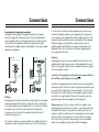
Owner’s manual
Introduction
Positioning
Congratulations on choosing the Acoustic Energy AEGIS EVOLUTION
Series — a range of powerful loudspeakers which feature metal
diaphragm technology and are capable of outstanding
performance. Please take a few moments to read this manual. The
advice it contains will enable you to get the very best performance
out of your Acoustic Energy loudspeakers.
Experiment with the best placement in the room to achieve a full, yet clean
bass response, a natural sounding mid range and a balanced spacious stereo
image. Trust your judgement and ears. For best stereo imaging the speakers
should be about as far apart as they are from the listening position. The
speakers should be equally distant from the listener[s] and should not be too
close to large items of furniture which may cause sound reflections. Ideally they
should be about 1m from the side walls and about 0.7m from the wall behind.
The spacing of the listening seat to the back wall may be quite critical for a
smooth deep bass.
The AEGIS EVOLUTION speakers utilise metal cone bass and mid-bass drive
unit technology, proven in the AE Reference series. The ultra rigid ceramic
layered alloy cones ensure pure piston action and also acts as a heat sink for
the bonded voice coil. These features provide exceptional clarity, transparency,
dynamics and power handling. The tweeters, or treble drivers, employ a highquality silk dome unit, built on a metal chassis, integrating smoothly with the
rest of the system. All drive units are fully magnetically shielded so that the
speakers can be used in close proximity to a TV screen or monitor for AV
applications. The AEGIS EVOLUTION loudspeakers use quality OFC internal
wiring, which enhances detail and transparency, and may be bi –wired as
desired.
Aegis Evo One
The AEGIS EVO ONE is best heard with the tweeters at, or just above, ear
height when the listener is seated. For serious listening the grilles are best
removed when the greatest clarity results.
Rigid support is essential for the speaker to develop its full detail and dynamic
performance. Good quality metal stands fitted with spikes, cones or other
methods of firm mounting are recommended. Stand mounting, placed as
recommended gives best stereo separation and depth.
If AEGIS EVO ONEs are shelf mounted, the support must be firm; cones, or felt
pads are recommended beneath the cabinets to reduce vibration coupling to
the support. Good quality wall brackets may be used, designed for speakers of
this size and weight. If wall mounted keep 1.5m from the side walls and angle
the speaker towards the listener area if possible; note that a corner position is
the poorest sounding for any speaker even if it is the loudest. AE can supply
damping plugs for the rear port to moderate the bass on request.
Positioning
Aegis Evo Three
Please unpack your AEGIS EVO THREE carefully on a carpet or similar surface.
Locate the plinths and fittings and, having carefully inverted the speaker, screw
the plinth to the base of the cabinet using the screws and pilot holes provided.
Please ensure that you have firmly screwed the plinth to the cabinet, failure to
do this will degrade performance.
There is a mass-loading compartment at the bottom of the cabinet.
You may choose to fill it with washed, fully dried non salt contaminated sand,
or suitable metal chips, via the hole at the back. A plastic bung is provided to
seal the cabinet. Mass loading will significantly improve the performance of
the speaker. If you decide not to mass-load the speakers, we still recommend
fitting the plastic bung to avoid unwanted resonance. Be aware that the
plastic bung has not been designed to be removable after insertion. You may
wish to use a temporary removable plug until you have made your decision
High tensile 8mm floor spikes and lock nuts are provided for use with the
plinth. This guarantees optimum coupling to the floor particularly in rooms
fitted with carpet. The spikes penetrate the carpet and couple the speaker
firmly to the floor structure below. The spikes (with lock nut screwed down to
the knurled part of the spike) should be fitted to the threaded insert in the
underside of the plinth while the speaker is still inverted. The speaker is now
ready for installation.. Any final adjustment of spikes to eliminate cabinet
wobble can now be made using a spirit level if required. The lock nuts should
be firmly tightened when the final adjustments to cabinet position and
alignment have been made and there is no rocking.
Closeness to room boundaries has a major impact on the low frequency
performance. The speakers should be kept away from corners (which will
produce bass booming) and they should be 0.6 m from the back walls, and a
greater distance e.g. 1m from the side walls.
Aegis Evo Centre
Position the AEGIS EVO CENTRE either immediately above or below the
television screen, whichever places the speaker nearest ear level when listening.
Line the front of the speaker approximately in line with the plane of the screen.
Fix the four self-adhesive foam-rubber feet to the base of the speaker to protect
both the surface on which the speaker stands and the underside of the speaker.
The feet also absorb vibration, which is especially important if placing the
speaker directly onto a thin television cabinet. If placement is on top of the
television, be aware that the flat surface depth may be limited, so ensure the
feet are placed accordingly.
When fine-tuning the Aegis EVO system, adjust the levels of the left, centre and
right channel speakers to give an even movement as sound images pan across
the screen. Most Home Theatre systems also include calibration sounds to help
set the right balance for the three front channels. The EVO Centre may also be
used as high powered surround channel speakers, mounted vertically, since
their particular ‘vocal precision’ tuning also suits them for boundary placement
on a wall.
Check that your amplifier is switched off before installing your loudspeakers. Failure
to do so may result in speaker or amplifier damage if the amplifier is energised and
delivering any power. The diagrams illustrate the connection for one loudspeaker
only.
Connections
Conventional [or single wire] connection
Normal passive wiring requires the supplied shorting links to be in place
between the high and low frequency sections. The positive (ribbed) cable
from the amplifier positive (or red) terminal should connect with the positive
(red) terminal on the loudspeaker. Similarly the negative (smooth) cable
should connect the amplifier negative terminal (black) to the negative terminal
(black) on the loudspeaker.
RIGHT SPEAKER
Safety Note: For bi-amping the shorting links must be removed. Failure to
do so will likely result in damage to your amplifiers.
RETAIN LINKS
FOR FUTURE USE
AMPLIFIER
MAIN
MAIN
R
L
R
to the LF section. Note that two cable terminations are connected to each
terminal of the amplifier, which may seem surprising for the inexperienced
user. As usual the positive (ribbed) cables from the amplifier positive (or red)
terminal should connect with the positive (red) terminals on the loudspeaker.
Similarly the negative (smooth) cables in each pair should connect the
amplifier negative terminal (black) to the negative terminals (black) on the
loudspeaker. If these are not correct the sound may be degraded and the
stereo image will be defocused.
Bi-Amping
Bi-amping adds a second, stereo power amplifier to the system. One stereo
amplifier drives the high frequency section of both loudspeakers; the second
drives the low frequency sections. Follow the amplifier instructions for joining
the low level signal connections
RIGHT SPEAKER
AMPLIFIER
Connections
L
Bi-Wiring
Bi-wiring separates the bass and treble paths and generally offers sound quality
advantages particularly with moderate cost cable. An extra set or alternatively
bi- wire type of cable is required. Important Note; to be effective, the shorting
links must be removed for the connection between the high and low
frequency sections on the back of the speaker and should be stored for
possible, later single wire use.
The two pairs of cables are connected in parallel to the amplifier terminals. At
the speaker, one cable of each pair should connect to the HF section and one
Connection for bi-amping is achieved in much the same way as bi-wiring. The
terminal (red, positive) of the chosen treble or high frequency amplifier should
be connected via the ribbed and /or colour coded cable to the positive (red)
HF terminal on the speaker. Similarly, the treble amplifier negative terminal is
connected to the negative (black) HF terminal on the speaker via the cable.
Repeat this process with the bass amplifier and LF terminal pair..
After wiring up; begin at very low volume, switch on the amplifier, select a
working signal source and then raise the volume to a moderate listening level,
checking that all the drivers in both speakers are working , that there is no
roughness or distortion, and that when the channel balance control is panned
from left to right the sound image moves correctly with the control action.
If all is ok then select your chosen volume and enjoy the often remarkable
advance in sound quality and clarity which results from Bi-Amping .
Specifications
Treble Unit:
25 mm silk fabric dome. Anti-reflection pole. Ferro fluid
cooled and damped. Magnetically shielded. Metal chassis
Mid/Bass Unit:
120 mm pressed-steel chassis. Pressed alloy cone with
32mm thermally bonded voice coil. High-power longthrow magnet system. Magnetically shielded.
Bass Unit:
160 mm die-cast chassis. Alloy cone, with 25 mm coil,
high power, long throw magnet system. Magnetically
shielded. [Aegis EVO Three ]
Cabinet:
15mm MDF enclosure. Low diffraction front baffle. Highpower, gas-flowed, low-turbulence bass reflex porting.
Terminals:
Gold-plated, bi-wire , binding posts.
Treble Unit
Mid/Bass Unit
Bass Unit
Power Handling
Crossover
Aegis Evo One
Aegis Evo Three
Aegis Evo Centre
1
1
0
100 Watt max.
3.3kHz 3rd order
1
1
1
150 Watt max.
3.5kHz 3rd,
330Hz 2nd order
40Hz – 20kHz
36Hz – 22kHz
90.5dB / 1W / 1M
8 Ohm
25mm front baffle
Full internal bracing
Double enclosure
16kg each
192 x 880 x 220 mm
1
1
1
150 Watt max.
3.1kHz 3rd,
275Hz 2nd order
60Hz – 20kHz
50Hz – 22kHz
91.5dB / 1W / 1M
8 Ohm
21mm front baffle
Lateral wave absorber
Frequency response ± 3dB
Frequency response - 6dB
Sensitivity
Impedance
Cabinet
50Hz – 20kHz
38Hz – 22kHz
89dB / 1W / 1M
8 Ohm
25mm front baffle
Full internal bracing
Weight (excl. packaging)
Dimensions (WxHxD)
7kg each
192 x 362 x 235 mm
7kg
460 x 172 x 192 mm
Warranty
Your Acoustic Energy loudspeakers are guaranteed against original defects in
materials, manufacture and workmanship for 3 years from the date of
purchase. Please retain all original packaging materials for possible future use.
We suggest that you complete details of purchase now and keep this
information in a safe place for future reference.
Under this warranty Acoustic Energy agrees to repair any defect or, at the
company’s discretion, replace the faulty component(s) without charge for parts
and labour. This warranty does not imply any acceptance by Acoustic Energy
or its agents for consequential loss or damage and specifically excludes fair
wear and tear, accident, misuse or unauthorised modification.
This warranty is applicable in the United Kingdom only and does not in any
way limit the customer’s legal rights. Claims and enquiries under the warranty
for AE products purchased outside the UK should be addressed to the local
importers or distributors.
If you have reason to claim under the warranty please contact your dealer in
the first instance.