1
AA G540_UG_EN-1.fm Page i Wednesday, August 9, 2006 8:59 AM
Acer Altos G540 Series
User’s Guide
AA G540_UG_EN-1.fm Page ii Wednesday, August 9, 2006 8:59 AM
Copyright © 2006 Acer Incorporated
All Rights Reserved.
Acer Altos G540 Series
User’s Guide
Changes may be made periodically to the information in this publication without obligation
to notify any person of such revision or changes. Such changes will be incorporated in new
editions of this manual or supplementary documents and publications. This company makes
no representations or warranties, either expressed or implied, with respect to the contents
hereof and specifically disclaims the implied warranties of merchantability or fitness for a
particular purpose.
Record the model number, serial number, purchase date, and place of purchase information in
the space provided below. The serial number and model number are recorded on the label
affixed to the unit. All correspondence concerning the unit should include these information.
No part of this publication may be reproduced, stored in a retrieval system, or transmitted, in
any form or by any means, electronic, mechanical, photocopy, recording, or otherwise,
without the prior written permission of Acer Incorporated.
Acer Altos G540 Series
Model Name : G540
Part Number: MU.R230E.001
Purchase Date:
Place of Purchase:
Acer and the Acer logo are registered trademarks of Acer Inc. Other company’s product
names or trademarks are used herein for identification purposes only and belong to their
respective companies.
AA G540_UG_EN-1.fm Page iii Wednesday, August 9, 2006 8:59 AM
iii
Notices
FCC notice
Class A devices do not have an FCC logo or FCC IDE on the label. Class B devices
have an FCC logo or FCC IDE on the label. Once the class of the device is
determined, refer to the following corresponding statement.
Class A equipment
This device has been tested and found to comply with the limits for a Class A
digital device pursuant to Part 15 of the FCC Rules. These limits are designed to
provide reasonable protection against harmful interference when the
equipment is operated in a commercial environment. This equipment
generates, uses, and can radiate radio frequency energy, and if not installed
and used in accordance with the instructions, may cause harmful interference to
radio communications. Operation of this equipment in a residential area is
likely to cause harmful interference, in which case the user will be required to
correct the interference at personal expense.
Notice: Shielded cables
All connections to other computing devices must be made using shielded cables
to maintain compliance with FCC regulations.
Notice: Peripheral devices
Only peripherals (input/output devices, terminals, printers, etc.) certified to
comply with the Class A limits may be attached to this equipment. Operation
with noncertified peripherals is likely to result in interference to radio and TV
reception.
Caution: Changes or modifications not expressly approved by the
manufacturer could void the user’s authority, which is granted by
the Federal Communications Commission, to operate this server.
AA G540_UG_EN-1.fm Page iv Wednesday, August 9, 2006 8:59 AM
iv
Use conditions
This part complies with Part 15 of the FCC Rules. Operation is subject to the
following two conditions: (1) this device may not cause harmful interference,
and (2) this device must accept any interference received, including interference
that may cause undesired operation.
Notice: Canadian users
This Class A digital apparatus meets all requirements of the Canadian
nterference-Causing Equipment Regulations.
Laser compliance statement
The CD-ROM drive in this server is a laser product. The CD-ROM drive’s
classification label (shown below) is located on the drive.
CLASS 1 LASER PRODUCT
CAUTION: INVISIBLE LASER RADIATION WHEN OPEN. AVOID EXPOSURE TO
BEAM.
AA G540_UG_EN-1.fm Page v Wednesday, August 9, 2006 8:59 AM
v
Important safety instructions
Read these instructions carefully. Save these instructions for future reference.
1
Follow all warnings and instructions marked on the product.
2
Unplug this product from the wall outlet before cleaning. Do not use
liquid cleaners or aerosol cleaners. Use a damp cloth for cleaning.
3
Do not use this product near water.
4
Do not place this product on an unstable cart, stand, or table. The product
may fall, causing serious damage to the product.
5
Slots and openings on the front and rear side of the chassis are provided
for ventilation; to ensure reliable operation of the product and to protect
it from overheating, these openings must not be blocked or covered. The
openings should never be blocked by placing the product on a bed, sofa,
rug, or other similar surface. This product should never be placed near or
over a radiator or heat register, or in a built-in installation unless proper
ventilation is provided.
6
This product should be operated from the type of power indicated on the
marking label. If you are not sure of the type of power available, consult
your dealer or local power company.
7
Do not allow anything to rest on the power cord. Do not locate this
product where persons will walk on the cord.
8
If an extension cord is used with this product, make sure that the total
ampere rating of the equipment plugged into the extension cord does not
exceed the extension cord ampere rating. Also, make sure that the total
rating of all products plugged into the wall outlet does not exceed the fuse
rating.
9
Never push objects of any kind into this product through chassis slots as
they may touch dangerous voltage points or short out parts that could
result in a fire or electric shock. Never spill liquid of any kind on the
product.
10
Do not attempt to service this product yourself, as opening or removing
covers may expose you to dangerous voltage points or other risks. Refer all
servicing to qualified service personnel.
vi
11
Unplug this product from the wall outlet and refer servicing to qualified
service personnel under the following conditions:
a
When the power cord or plug is damaged or frayed.
b
If liquid has been spilled on the product.
c
If the product has been exposed to rain or water.
d
If the product does not operate normally when the operating
instructions are followed. Adjust only those controls that are covered
by the operating instructions since improper adjustment of other
controls may result in damage and will often require extensive work
by a qualified technician to restore the product to normal condition.
e
If the product has been dropped or the chassis has been damaged.
f
If the product exhibits a distinct change in performance, indicating a
need for service.
12
Replace the battery with the same type as the product's battery we
recommend. Use of another battery may present a risk of fire or explosion.
Refer battery replacement to a qualified service technician.
13
Warning! Batteries may explode if not handled properly. Do not
disassemble or dispose of them in fire. Keep batteries away from children.
Promptly dispose used batteries according to regulations applicable to
your area.
14
Use only the proper type of power supply cord set (provided in your
accessories box) for this unit. It should be a detachable type: UL listed/CSA
certified, type SPT-2, rated 7A 125V minimum, VDE approved or its
equivalent. Maximum length is 15 feet (4.6 meters).
System specifications
Performance
Mechanical
Environmental
Hardware options
External and internal structure
Front bezel
Front panel
Rear panel
Internal components
System boards
Mainboard
Backplane board
SAS controller board
BMC module
ARMC/3 module
System LED indicators
Front panel LED indicators
Hot-plug HDD LED indicator
LAN port LED indicators
Power supply module LED indicators
2 System setup
Setting up the system
Pre-installation requirements
Connecting peripherals
Turning on the system
Power-on problems
Configuring the system OS
Rack mount configuration
Turning off the system
3 System upgrade
Installation precautions
ESD precautions
Pre-installation instructions
Post-installation instructions
Opening the server
Removing the side panel
Removing the front bezel
Configuring the hard drive
1
3
3
6
6
7
8
8
9
11
13
14
14
17
18
19
20
21
21
22
22
23
25
27
27
28
29
30
31
32
33
35
37
37
38
38
39
39
40
41
Contents
1 System tour
viii
Installing a HDD cage
Removing a HDD cage
Installing an additional hard drive
Configuring a 5-25 inch storage device
Upgrading the processor
Upgrading the system memory
Installing an expansion card
Installing the SAS controller board
Installing the BMC module
Installing the ARMC/3 module
Installing a redundant power supply module
4 System BIOS
BIOS overview
Entering BIOS setup
BIOS setup primary menus
BIOS setup navigation keys
Main menu
Advanced menu
Advanced Processor Options
Memory Configuration
Advanced Chipset Control
PCI Configuration
I/O Device Configuration
IDE Configuration
Floppy Configuration
Boot Configuration
DMI Event Logging
Security menu
Setting a system password
Changing a system password
Removing a system password
Server menu
System Management
Console Redirection
Event Log Configuration
Boot menu
Exit menu
41
44
45
48
50
55
60
62
63
64
66
69
71
72
72
73
74
75
76
78
79
80
81
83
85
86
87
89
90
91
91
92
93
93
95
96
97
ix
5 System troubleshooting
99
Resetting the system
Initial system startup problems
Initial troubleshooting checklist
Hardware diagnostic testing
Checking the boot-up status
Verifying the condition of the storage devices
Confirming loading of the operating system
Specific problems and corrective actions
101
102
103
104
104
105
105
106
Appendix A: Server management tools
Server management overview
RAID configuration utilities
Onboard SATA RAID Configuration Utility
LSI 1068 SAS Configuration Utility
LSI MegaRAID SAS RAID Configuration Utility
Appendix B: Rack mount configuration
Rack installation information
Rack installation precautions
Rack mount kit
Vertical mounting hole pattern
Rack installation procedures
Preparing the server for rack installation
Preparing the rack for server installation
Installing the server in the system rack
Installing the cable arm option
Index
111
113
114
114
116
117
119
121
121
122
124
125
125
127
129
130
133
x
1 System tour
The Acer Altos G540 server is a fully modular
dual-processor system featuring the latest in
computing technology. It host a range of
powerful and flexible features designed to
meet the needs of various network
environments. From simple networking
functions to computing intensive applications,
the Altos G540 delivers.
3
System specifications
This section lists down the impressive computing features of the
Altos G540 system.
Performance
Processor
•
Two Intel LGA771 processor sockets supporting Dual-Core
Intel® Xeon™ processor
•
2x 2 MB or 4 MB external L2 cache
•
1066 or 1333 MHz FSB speed
•
Support for the following Intel technologies:1
•
Hyper-Threading (HT) Technology
•
Intel Extended Memory 64 Technology (EM64T)
•
Virtualization Technology
•
Demand Based Switching Technology
•
Compatibility with the broadest range of 32- and 64-bit
applications
•
Execute Disable Bit and reliable RAS security features
Chipset
•
North bridge - Intel 5000P Memory Controller Hub (MCH)
•
South bridge - Intel 6321ESB I/O Controller Hub (ICH)
Memory
•
Eight fully-buffered DIMM (FBD-DIMM) slots supporting 240-pin,
DDR2 667 FBD ECC modules
•
16 GB maximum memory capacity
•
Quad channel memory bus
1
For more information on these Intel technologies, visit the Intel Xeon web
site at http://www.intel.com/products/processor/xeon/index.htm.
4
1 System tour
PCI interface
•
•
Six PCI bus slots with three separate bus segments
•
Three PCI Express x8 bus slots
•
Two 64-bit, 66/100 MHz PCI-X bus slots
•
One 32-bit/33 MHz PCI bus slot
One dedicated PCI-X slot for the optional SAS controller board.
Video controller
•
Integrated ATI ES1000 chipset
•
16 MB DDR SDRAM
Networking
•
Two Gigabit Ethernet LAN ports (RJ-45)
•
Intel I/O Acceleration Technology (IOAT) support via Intel ESB2
Media storage
•
Two 5.25-inch device bays support:
•
CD-ROM, DVD-ROM, DVD-RW, DVD combo drive
•
DAT tape drive
•
AIT tape drive
•
LTO-2 half-height tape drive
•
3.5” floppy disk drive (FDD)
•
Two hard disk drive (HDD) cage bays support:
•
•
Hot-swap or easy-swap HDD cages
•
Up to eight SAS/SATA2 drive support (four drives per HDD
cage)
Embedded SATA2 controller with six onboard connectors
5
I/O ports
•
Two front USB 2.0 ports
•
Parallel port
•
PS/2 keyboard port
•
Four rear USB 2.0 ports
•
PS/2 mouse port
•
•
Serial port
Two Gigabit LAN ports
(RJ-45)
•
Monitor port
Power supply and system fan
•
610-watts power supply with redundant option
•
System fan with redundant option
Hardware monitoring and server management
•
Winbond W83792D hardware monitoring IC for voltage,
temperature, and fan speed detection
•
LED indicators for constant monitoring of basic system function
•
Acer Server Management (ASM) monitors potential problem spots
in the network environment
Operating system
•
Microsoft® Windows® Server 2003
•
Microsoft Windows Server 2003, x64 Edition
•
Red Hat® Enterprise Linux® 4.0
•
Red Hat Enterprise Linux 4.0, x86_64
•
Novell® NetWare® 6.5
•
SUSE Linux® Enterprise Server 9.0
•
SUSE Linux Enterprise Server 9.0, EM64T
6
1 System tour
Mechanical
•
Chassis
•
Tool-less chassis design for easy hardware access and
configuration
•
Tower and rack-mount (5U, tray-less) setup options
•
Dimensions
– Height: 445 mm (17.5 in)
– Depth: 212 mm (8.3 in)
– Width: 550 mm (21.6 in)
•
Mainboard
•
Dimensions (length x width): 304.8 x 330.2 mm (12 x 13 in)
•
Platform: Extended ATX (EATX)
Environmental
•
Temperature
•
Operating: +10° to +35°C with the maximum rate of change
not to exceed 10° per hour.
•
Non-operating: -40° to +70°C
•
Humidity, non-operating : 90%, non-condensing @ 35°C
•
Vibration, operating: Half sine, 2g peak, 11 m/sec
•
System cooling: 2081.5 BTU/hour
7
Hardware options
Note: To purchase the any of the following hardware options,
contact your local Acer representative.
•
Media storage
•
LSI 1068 SAS controller board provides both SAS and SATA2
support
•
LSI MegaRAID SAS RAID controller board supports:
– Hardware RAID 0, 1, 5, 10, and 50 levels
– Backup battery unit (BBU) option
•
•
•
Ultra 320 SCSI HBA (for backup devices only)
Redundant modules
•
Hot-swap redundant power supply
•
Redundant system fan
Server management
•
BMC (Baseboard Management Controller) module
– IPMI (Intelligent Platform Management Interface) 2.0
compliant
– In-band and out-band server management
•
ARMC/3 (Acer Remote Management Card/3) module
– High performance KVM redirection
– Includes a dedicated NIC port
– USB mouse, keyboard, and media redirection
8
1 System tour
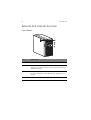
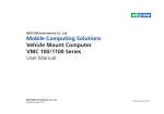
External and internal structure
Front bezel
No.
Component
1
Side panel release button
2
Security keylock
This lock secures the bezel door to protect the server unit from
unauthorized access.
3
LED indicator panel
For more information on the LED indicators description, go to
page 21.
4
Bezel door
9
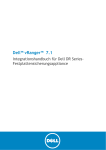
Front panel
No.
Icon
Component
Description
1
DVD-ROM drive Eject
button
Press this button to open the DVD
drive tray.
2
DVD-ROM drive
activity indicator
When the LED indicator is lit, there
is an ongoing DVD drive activity.
3
DVD-ROM drive
mechanical eject hole
When the DVD drive tray get
stucked, insert a paperclip to this
hole to manually eject the tray.
4
DVD-ROM drive
Disk drive for reading CD, VCD, and
DVD contents.
5
5.25-inch drive bay
Allows installation of additional
storage devices. Go to page 4 for a
list of supported devices.
6
Power indicator
Indicates the system power status
(green).
7
HDD activity
indicator
Indicates the status of a system
hard drive (green/amber).
8
Status/fault indicator
Indicates the status of the system
operations (green/amber).
10
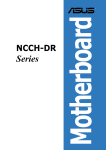
No.
1 System tour
Icon
Component
Description
9
LAN port 1/2 status
indicators
Indicate the system network
connection status.
10
Hot-plug HDD
activity indicator
Indicates the status of a hot-plug
HDD installed in the system (green
/amber).
11
HDD cage
Supports four hot-plug or
easy-swap SAS or SATA2 HDDs.
12
HDD cage bay
Supports an optional four-bay HDD
cage (hot-plug or easy-swap).
13
USB 2.0 ports
Connects to USB devices.
14
Power button
Press to turn the server on/off, or to
put it in standby mode.
15
FDD Eject button
Press this button to eject the floppy
disk from the FDD.
16
Floppy disk drive
Disk drive for reading floppy disks.
17
FDD activity indicator
When the LED indicator is lit, there
is an ongoing FDD activity.
11
Rear panel
No.
Icon
Component
Description
1
Power supply
module
release latch
Push down the latch to disengage the
module from the chassis.
2
Power supply
module cord
socket
Connect the system power cord here.
3
Main power
supply module
Provides the system’s main power
supply.
4
PS/2 mouse
port
Connects to a PS/2 mouse.
5
PS/2 keyboard
port
Connects to a PS/2 keyboard.
6
Parallel port
Connects to parallel devices.
7
Serial port
Connects to serial devices.
8
Monitor port
Connects to monitors.
12
No.
1 System tour
Icon
Component
Description
9
Unit
identification
(UID) switch/
indicator
Press to mark a particular server unit
within a server group (when
rack-mounted) for purpose of
identification during servicing or
maintenance procedures. (blue)
10
USB 2.0 ports
Connects to USB devices.
11
Gigabit LAN
ports 1/2
Connects to an Internet or intranet
network.
12
PCI slot covers
Protects the vacant expansion slots.
13
System fan
Regulates the system airflow.
14
Redundant
power supply
module bay
Accommodates an optional hot-swap
redundant power supply module.
15
Power supply
module fault
indicator
Indicates the occurrence of a fault
condition in the power supply
module. (green/amber)
16
Power supply
module status
indicator
Indicates the status of the power
supply module. (green)
13
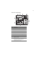
Internal components
No.
Component
1
Redundant power supply module bay
2
Air duct
3
Heat sink fan (HSF) assemblies
4
Release sliders for the 5.25-inch devices
5
Release sliders for the HDD cages
6
Mainboard
7
PCI slot lock levers
8
System fan
Users have the option to purchase a
redundant system fan unit.
14
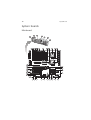
System boards
Mainboard
1 System tour
15
No.
Code
Description
1
CN2
Top: PS/2 mouse port
Bottom: PS/2 keyboard port
2
COM1
Serial port
3
LPT1
Parallel/printer port
4
VGA1
Monitor port
5
SW1
UID switch
6
—
Gigabit LAN ports
7
—
USB 2.0 ports
8
DIMMA1
DIMMA2
DIMMB1
DIMMB2
Branch 0 FBD slots
9
DIMMC1
DIMMC2
DIMMD1
DIMMD2
Branch 1 FBD slots
10
FAN_R2
System fan 2 cable connector
11
FAN_R1
System fan 1 cable connector
12
ATX1
24-pin ATX power connector
13
ATX3
8-pin ATX power connector
14
FAN_CPU1
Processor 1 HSF cable connector
15
U47
Intel 5000P MCH (north bridge)
16
CPU 1
Processor 1 socket
17
U108
Winbond W83792D hardware monitoring IC
18
CPU 2
Processor 2 socket
19
FAN_CPU2
Processor 2 HSF cable connector
16
1 System tour
No.
Code
Description
20
JP_PASS1
Clear password jumper
Open – Normal (default)
Close – Clear password
21
JP_REC1
BIOS recovery jumper
1-2 – Enable BIOS recovery
2-3 – Disable (default)
22
IDE1
IDE cable connector
23
USB1 and
USB2
Front USB connectors
24
SATA HDD 0-5
SATA2 data cable connectors
25
CLR_CMOS1
Clear CMOS jumper
Close 1-2 – Normal CMOS settings (default)
Close 2-3 – Clear CMOS, restore system defaults
26
U69
Intel ESB2 ICH (south bridge)
27
BAT1
CMOS battery
28
U61
BIOS flash ROM (Read-Only Memory)
29
FDC1
FDD cable connector
30
U45
ITE ITE8712F-A I/O controller
31
PCI7
32-bit/33 MHz PCI expansion slot
32
JP_FP1
Signal cable connector for the front panel LED
indicators/power button
33
—
Chassis intrusion connector
34
IPMB_6
BMC and ARMC/3 modules slot
35
SODIMM1
SAS controller board slot
36
U10
ATI ES1000 video controller
17
No.
Code
Description
37
PCI-E 4
PCI-E 5
PCI Express x8 expansion slots
38
U4
Video memory
PCI-X 2
64-bit, 66/100 MHz PCI-X expansion slots
39
PCI-X 31
40
PCI-E 1
PCI Express x8 expansion slot
1 The PCI-X 3 slot (green) supports the installation of a SAS ZCR (Zero Channel RAID) option
card.
Backplane board
The backplane board attached to rear of the hot-plug HDD cage is
what differentiate it from the easy-swap HDD cage model.
No.
Code
Description
1
J7 to J10
SAS/SATA2 HDD access LED control jumpers
Close 2-3 – HDD LED control via pin 11(default)
2
SGIO_JP
Debug/diagnostic connector
3
JP2
SAF-TE firmware flash connector
4
J4
Backplane board peering cable connector
5
CN1 and CN2
Power cable connectors for the SAS/SATA2 HDD
18
1 System tour
No.
Code
Description
6
792D_ID1
HDD cage ID setting jumper
Close 1-2 – 5C (default for top HDD cage)
Close 2-3 – 58 (default for bottom HDD cage)
7
SAS/CON
SAS/SATA2 HDD data cable connector
8
J5
Backplane board management cable connector
9
SATA/SAS_1-4
SAS/SATA2 HDD connectors
SAS controller board
This controller board enables the installation of a SAS HDD.
No.
Code
Description
1
SODIMM_CON1
Controller mainboard connector
2
JP3
SAS controller RAID jumper
Set to Close 2-3 to enable firmware RAID/
0 channel RAID support (default)
3
SAS1-1
SAS data cable connector 1
4
U1
LSI SAS 1068 chipset
5
SAS1-2
SAS data cable connector 2
6
SU3
Flash ROM
7
U5
nvSRAM (non-volatile SRAM)
19
BMC module
The optional BMC module is the meeting point between the server
hardware and the system management software. In conjunction with
the mainboard hardware monitor, it allows system administrators to
manage the system remotely over a network.
No.
Code
Description
1
SODIMM1
ARMC/3 module connector
2
DIMM1
BMC module mainboard connector
3
U3
SDRAM (Synchronous Dynamic Random Access Memory)
4
U1
H85/216x BMC chipset
20
1 System tour
ARMC/3 module
The optional ARMC/3 module expands the server’s remote
management function through its own dedicated NIC port. System
administrators can now have full remote access to the server regardless
of its condition. Options to access server configuration, performance
and storage; view a summary of key components; and monitor system
health events are readily access using a simple browser.
No.
Code
Description
1
LAN1
Dedicated NIC port cable connector
2
U6
SRAM (Static Random Access Memory)
3
U9
SDRAM
4
SODIMM1
ARMC/3 module mainboard connector
5
U8
Flash ROM
6
U5
SRAM
7
U1
Peppercon KIRA 100 chipset
21
System LED indicators
This section discusses the different LED indicators located on the:
•
Front panel
•
Hot-plug HDD carrier
•
LAN port
•
Power supply module
Knowing what each LED indicator signifies can aid in problem
diagnosis and troubleshooting.
Front panel LED indicators
The five LED indicators mounted on the front panel allow the constant
monitoring of basic system functions. These indicators remain visible
even when the bezel door is closed.
Indicator
Color
Status
Description
Power
Green
On
The system has AC power and is
powered on.
Blinking
The system is in standby mode.
Green
Blinking
There is an ongoing HDD activity.
Amber
On
An system hard drive failed.
Green
On
System in normal mode.
Amber
On
Critical system threshold breach
Access the Setup utility and view the
system event log for details.
Green
On
Network connection is established.
Blinking
Network connection is established
and is running at supported speed.
Off
Network connection is not
established.
HDD activity
Status/fault1
LAN port 1/2
connection
1 The status/fault LED indicator is only enabled when the optional BMC module is installed
on the mainboard. To purchase this option, contact your local Acer representative.
22
1 System tour
Hot-plug HDD LED indicator
A drive activity LED indicator is mounted on the hot-plug HDD carrier.
The table below lists the possible drive states.
Status
Green
Amber
Description
HDD access
Blinking
—
Ongoing hot-plug HDD activity
HDD failure
—
On
Hot-plug HDD failure
HDD rebuild
Flashing green/amber
HDD is rebuilding data.
LAN port LED indicators
Indicator
Color
Status
Description
Network
speed
(top)
Amber
On
GbE link network access
Green
On
100 Mbps link network access
Off
10 Mbps link network access
On
Active network link
Blinking
Ongoing network data activity
Off
Off-line network
Network
connection
(bottom)
Green
23
Power supply module LED indicators
Indicator
Color
Status
Description
Status (top)
Green
On
Output requirements are met.
Off
AC power is disconnected from the
module.
Green
On
Input voltage requirements are met.
Amber
On
• Overvoltage
• Overcurrent
Fault (bottom)
• Output short circuit
Off
AC power is disconnected from the
module.
24
1 System tour
2 System setup
This chapter gives you instructions on how to
prepare the system for operation. Procedures for
connecting peripherals are also explained.
27
Setting up the system
Pre-installation requirements
Selecting a site
Before unpacking and installing the system, select a suitable site for
the system for maximum efficiency. Consider the following factors
when choosing a site for the system:
•
Near a grounded power outlet
•
Clean and dust-free
•
Stable surface free from vibration
•
Well-ventilated and away from sources of heat
•
Secluded from electromagnetic fields produced by electrical
devices such as air conditioners, radio and TV transmitters, etc.
Checking the package contents
Check the following items from the package:
•
Acer Altos G540 system
•
Acer EasyBUILDTM DVD Pack
•
Acer Altos G540 accessory box
•
System keys (attached to the rear of the bezel door)
If any of the above items are damaged or missing, contact your dealer
immediately.
Save the boxes and packing materials for future use.
28
2 System setup
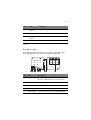
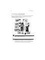
Connecting peripherals
The color-coded I/O port panel on the system rear accepts a variety of
compatible peripherals. Refer to the figure below for specific
connection instructions for each port.
Note: Consult the operating system manual for information on
how to configure the network setup.
Caution: Do not route the power cord where it will walked on or
pinched by items placed against it. The server is designed to be
electrically grounded (earthed). To ensure proper operation, plug
the power cord into a properly grounded AC outlet only.
29
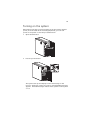
Turning on the system
After making sure that you have properly set up the system, applied
power, and connected all the necessary peripherals, you can now
power on the system. Follow the procedure below.
1
Open the bezel door.
2
Press the power button.
The system starts up and displays a welcome message on the
monitor. After that, a series of power-on self-test (POST) messages
appears. The POST messages indicate if the system is running well
or not.
30
2 System setup
Note: If the system does not turn on or boot after pressing the
power button, go to the next section for the possible causes of the
boot failure.
Aside from the POST messages, you can determine if the system is in
good condition by checking if the following occurred.
•
The power status indicator on the front panel lights up green.
•
The Num Lock, Caps Lock, and Scroll Lock indicators on the
keyboard light up.
Power-on problems
If the system fails to boot after you have applied power, check the
following factors that might have caused the boot failure.
•
The external power cord may be loosely connected.
Check the power cord connection from the power outlet to the
power cord socket on the rear panel. Make sure that the cord is
properly connected to the power outlet and to the power cord
socket.
•
No power comes from the grounded power outlet.
Have an electrician check your power outlet.
•
Loose or improperly connected internal power cables.
Check the internal cable connections. If you are not confident to
perform this step, ask a qualified technician to assist you.
Warning! Make sure all power cords are disconnected from
the electrical outlet before performing this task.
Note: If you have gone through the preceding actions and the
system still fails to boot, ask your dealer or a qualified technician
for assistance.
31
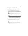
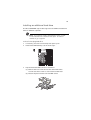
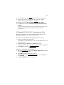
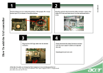
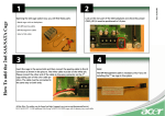
Configuring the system OS
The Altos G540 comes with Acer EasyBUILD that allows users to
conveniently install the preferred operating system. To start using
EasyBUILD, follow the steps below.
1
Locate the EasyBUILD DVD included in the system package.
2
With the system turned on, press the DVD-ROM drive Eject button.
3
When the disc tray slides open, insert the EasyBUILD DVD with the
label side of the disc facing upward.
Note: When handling the disc, hold it by the edges to avoid
smudges or fingerprints.
4
Gently press the disc down to make sure that it is properly
inserted.
Caution: While pressing the disc, be careful not to bend the disc
tray. Make sure that the disc is properly inserted before closing
the disc tray. Improper insertion may damage both the disc and
the DVD-ROM drive.
5
Press the drive Eject button again to close the disc tray.
6
The Acer EasyBUILD sequence begins. Follow all onscreen
instructions.
For more information, refer to the EasyBUILD Installation guide.
Note: EasyBUILD only supports the Microsoft and Red Hat Linux
operating systems. The Windows or Red Hat installation disc(s) is
required to install the OS.
32
2 System setup
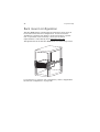
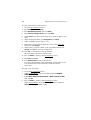
Rack mount configuration
The Altos G540 server is a dual-platform system that can be set up in
both tower and rack-mount configurations. A rack mount kit is
available for customers who prefer to mount the server in a system
rack. To purchase a rack mount kit, contact your local Acer
representative or order directly from http://www.acer.com/.
The figure below shows the Altos G540 server in a rack-mount position.
For instructions on tower-to-rack configuration, refer to “Appendix B:
Rack mount configuration” on page 119.
33
Turning off the system
There are two ways to turn off the server—via software or via
hardware. The software procedure below applies to a system running
on a Windows OS. For other NOS shutdown procedures, refer to the
related user documentation.
To turn off the system via software:
1
Press Ctrl+Alt+Delete on the attached keyboard or click the Start
on the Windows taskbar.
2
Select Shut Down.
3
Select Shut down from the drop-down menu, then click OK.
To turn off the system via hardware:
If you cannot shut down the server via software, press the power
button for at least four seconds. Quickly pressing the button may put
the server in a Suspend mode only.
34
2 System setup
3 System upgrade
This chapter discusses the precautionary
measures and installation procedures you
need to know when upgrading the system.
37
Installation precautions
Before you install any server component, it is recommended that you
read the following sections first. These sections contain important ESD
precautions along with pre-installation and post-installation
procedures.
ESD precautions
Electrostatic discharge (ESD) can damage static-sensitive hardware
components, such as the processor, disk drives, and the system boards.
Always observe the following precautions before you install a server
component:
•
Do not remove a component from its protective packaging until
you are ready to install it.
•
Do not touch the component pins, leads, or circuitry.
•
Components with a Printed Circuit Board (PCB) assembly should
always be laid with the assembly-side down.
•
Wear a wrist grounding strap and attach it to a metal part of the
server before handling components. If a wrist strap is not
available, maintain contact with the server throughout any
procedure requiring ESD protection.
•
Keep the work area free of nonconductive materials, such as
ordinary plastic assembly aids and foam packing.
38
3 System upgrade
Pre-installation instructions
Perform the steps below before you open the server or before your
remove or replace any component.
Warning! Failure to properly turn off the server before you
start perform any hardware configuration may cause
serious damage and bodily harm. Do not attempt the
procedures described in the following sections unless you
are a qualified service technician.
1
Turn off the server and all connected peripherals.
2
Unplug all power cables from their outlets.
3
Disconnect all telecommunication cables from their ports.
4
Place the server on a flat, stable surface.
5
Open the server according to the instructions on page 39.
6
Follow the ESD precautions described in the previous section when
handling a server component.
Post-installation instructions
Perform the steps below after installing a server component.
1
See to it that all components are installed according to the
described step-by-step instructions.
2
Reinstall any expansion board(s), peripheral(s), bracket (s) and
system cable(s) that have previously been removed.
3
Reinstall the side panel.
4
Reconnect the power, peripheral, and telecommunication cables.
5
Turn on the system.
39
Opening the server
Caution: Before you proceed, make sure that you have turned
off the system and all peripherals connected to it. Read the
“Pre-installation instructions” section on page 38.
You need to open the server before you can install upgrade
components. The front bezel and (left) side panel are removable to
allow access to the server’s internal components. Refer to the
following sections for instructions.
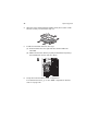
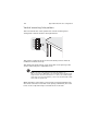
Removing the side panel
1
Perform the pre-installation instructions described on page 37.
2
Remove the side panel.
(1) Remove the two screws located on the rear edge of the
side panel.
(2) Press the side panel release button.
(3) Slide the side panel toward the rear of the chassis to
disengage it.
40
3 System upgrade
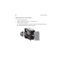
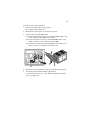
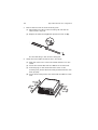
Removing the front bezel
1
Remove the side panel.
Refer to the previous section for instructions.
2
Remove the front bezel.
(1) Release the bezel door retention tabs from the chassis interior.
(2) Pull the bezel away from the chassis.
41
Configuring the hard drive
The two HDD cage bays of the Altos G540 accommodates both
hot-plug and easy-swap HDD cage models. The main difference
between these two cage models is the presence of a backplane board
on the rear side of the hot-plug HDD cage. Both cage models support
up to four SATA2 or SAS hard disk drives.
The system ships out with only a single HDD cage occupying the top
cage bay. You have the option to purchase an extra HDD cage to
provide the system with additional storage capacity and scalability.
Contact your local Acer representative for more information.
Note: The HDD cage comes with HDD dummy covers. You need
to purchase a blank HDD carrier to install a hard drive.
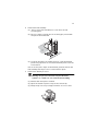
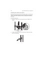
Installing a HDD cage
1
Perform the pre-installation instructions described on page 37.
2
Remove the HDD cage bay metal cover from the front chassis.
(1) Remove the one screw that secures the cover.
(2) Detach the cover from chassis.
Store this cover for future reinstallation.
42
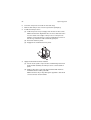
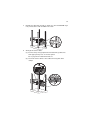
3
3 System upgrade
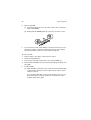
Install the HDD cage.
(1) Slide the cage into the lower bay with the HDD carriers facing
front.
The cage locked to the chassis with an audible click.
If you have installed a hot-plug HDD cage, proceed to next
step for related drive cable connections.
Drive cable connections for an easy-swap HDD can be found
on page page 47.
(2) Connect the following cables to the hot-plug HDD cage
backplane board.
(1) Connect the hard drive power cables to the CN1 and CN2
connectors of the backplane board.
(2) Connect the SAS/SATA2 cable to the SAS/CON connector
of the backplane board.
43
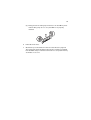
(3) Connect the other end of the SAS/SATA2 cable to the
SAS1-1 connector of the SAS controller board.
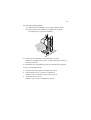
4
Remove the HDD cage bay plastic cover from the front bezel.
(1) Use a flat-blade screwdriver to disengage the tabs on the top
edge of the cover from its bezel slots.
(2) Detach the cover from the bezel.
Store this cover for future reinstallation.
5
Observe the post-installation instructions described on page 38.
For instructions on how to install a hard drive in an easy-swap HDD
cage, go to page 47.
For instructions on how to install a hard drive in a hot-plug HDD
cage, go to page 45.
44
3 System upgrade
Removing a HDD cage
1
Perform the pre-installation instructions described on page 37.
2
Prepare the HDD cage for removal.
3
•
For a hot-plug HDD cage, disconnect the data and power
cables from the backplane board, then remove all HDDs from
the cage.
•
For an easy-swap HDD cage, disconnect the data and power
cables from their HDD connectors, then remove all HDDs from
the cage.
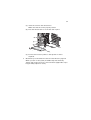
Remove the HDD cage.
(1) Move the release slider all the way up to eject the hot-plug
HDD cage.
(2) Remove the cage from the HDD bay.
4
Observe the post-installation instructions described on page 38.
45
Installing an additional hard drive
The Altos G540 HDD cage models supports both SATA2 and SAS hard
drives in different capacities.
Note: If you intend to install a SAS hard drive model, you first
need to install the SAS controller board option. For related
instructions, go to page 62.
To install a hot-plug hard drive:
1
If necessary, unlock the front bezel, then pull it open.
2
Remove the HDD dummy cover from the cage.
3
Prepare the blank HDD carrier for installation.
(1) Remove the four screws that secures the blank frame.
You will use these screws to secure the hard disk later.
(2) Detach the plastic frame from the HDD carrier.
46
3 System upgrade
4
Align the new hard disk with the HDD carrier, then secure it with
the four screws you removed in step 3-1.
5
Install the new hard drive into the cage.
(1) Slide the drive into the cage with the carrier handle still
extended.
(2) Make sure that the drive is properly inserted before pushing
the handle back until it clicks into place.
6
Set up the new hard drive’s RAID configuration.
For related instructions, go to the “RAID configuration utilities”
section on page 114.
47
To install an easy-swap hard drive:
1
Remove the side panel from the chassis.
Go to page 39 for instructions.
2
Observe steps 2 through 5 of the previous section.
3
Connect the easy-swap HDD cables.
(1) Connect the power connectors of the SAS/SATA2 cable to the
power supply module HDD power cables.
(2) Connect the data connectors of the SAS/SATA2 cable to the
signal connectors of the of the easy-swap HDDs.
(3) Connect the other end of the SAS/SATA2 power cable to the
SAS1-1 connector of the SAS controller board.
4
Observe the post-installation instructions described on page 38.
5
Set up the new hard drive’s RAID configuration.
For related instructions, go to the “RAID configuration utilities”
section on page 114.
48
3 System upgrade
Configuring a 5-25 inch storage device
The three 5.25-inch device bays support a variety of storage devices for
additional storage capacity and scalability. Go to page 4 for a list of
supported storage devices.
By default, the system ships with a DVD-ROM drive installed on the
topmost device bay, and a floppy drive on the bottom-most device bay.
You can choose to replace these default drives, or you can install a new
storage device on the middle device bay.
To install an optional storage device:
1
Perform the pre-installation instructions described on page 37.
2
If you intend to replace a default storage device—the DVD drive or
the floppy drive—go to the next step.
If you intend to install a new storage device on the middle device
bay, go to step 5.
3
4
Disconnect the power and data cables (IDE or FDD data cable)
from rear of the old drive.
Remove the default drive you intend to replace.
(1) Move the release slider of the selected drive to the unlock
position
.
(2) Pull the drive out of the device bay.
The figure below shows how to uninstall the DVD-ROM drive.
Proceed to step 6 for instructions on how to install a new
storage device.
49
5
Remove the two screws that secure the cover of the empty
5.25-inch drive bay (1), then detach the cover (2).
Keep this cover for future reinstallation.
6
Install the new 5.25-inch storage device.
The instructions given below apply to a regular 5.25-inch storage
device. If you intend to replace or install a floppy drive, refer to
the documentation that came with the new drive for instructions
on how to set up the FDD conversion kit.
(1) Install the new 5.25-inch drive into the drive bay.
(2) Move the release slider into the lock position
.
(3) Connect the power and IDE cables to the new 5.25-inch drive.
7
Observe the post-installation instructions described on page 38.
50
3 System upgrade
Upgrading the processor
This section explains the procedures for removing and installing the
processor and heat sink fan (HSF) assembly.
Processor configuration guidelines
The mainboard has two LGA771 processor sockets supporting
Dual-Core Intel Xeon processors. You have the option to upgrade the
default processor or install a second one for a dual-processor
configuration.
Observe the following guidelines when replacing or installing a
processor.
•
The CPU 1 socket must always be populated. If no processor is
installed in this socket, the system will fail to boot.
•
Before removing a processor, make sure to back up all important
system files.
•
When installing a second processor, make sure it has same
stepping and frequency specifications as the default processor.
•
Handle the processor and the HSF assembly carefully. Damage to
either may prevent the system from functioning properly.
Note: A long-nosed screwdriver is needed to remove/install the
HSF assembly.
To upgrade the default processor:
1
Perform the pre-installation instructions described on page 37.
2
Lay the server on its side (components showing).
3
Disconnect the processor 1 HSF cable from its mainboard
connector.
51
4
Remove the HSF assembly.
(1)
Use a long-nosed screwdriver to loosen the four HSF
mounting pins.
(2) Once you have loosened all four mounting pins, lift the HSF
away from the mainboard.
(3) Lay down the HSF in an upright position—with the thermal
patch facing upward. Do not let the thermal patch touch the
work surface.
Use an alcohol pad to wipe off the thermal grease from both the
HSF assembly and the processor socket retention plate.
5
Remove the default processor.
Warning! The processor becomes very hot when the
system is on. Allow it to cool off first before handling.
(1) Release then lift up the load lever.
(2) Open the retention plate to expose the socket body.
(3) Grasp the processor by its edges and lift it out of its socket.
52
3 System upgrade
6
Store the old processor inside an anti-static bag.
7
Remove the new processor from its protective packaging.
8
Install the new processor.
(1) Hold the processor by its edges, then insert it in the socket.
Make sure that the alignment tabs on the socket fit the two
notch located on the edge of the processor. The pins are
keyed in such a way that you cannot install the processor in
the wrong orientation without bending the pins.
(2) Close the retention plate.
(3) Engage the load lever back into place.
9
Apply the thermal interface material.
(1) Use an alcohol pad to wipe off the old thermal grease from
both the HSF assembly and the processor socket retention
plate.
(2) Apply a thin layer of an Acer-approved thermal interface
material before installing the HSF.
Make sure that only a very thin layer is applied so that both
contact surfaces are still visible.
53
10 Reinstall the HSF assembly.
(1) Align then insert the HSF on top of the retention plate.
(2) Use a long-nosed screwdriver to tighten the four HSF
mounting pins to secure the assembly.
11 Reconnect the HSF cable to its mainboard connector.
Refer to the “Mainboard” section on page 14 for the location of
the HSF connectors.
12 Observe the post-installation instructions described on page 38.
To install a second processor:
1
Perform steps 1 through 4 of the previous section.
2
Prepare the processor socket 2 for installation.
Refer to steps 5-1 and 5-2 of the previous section.
3
Install the new processor.
Refer to steps 7 and 8 of the previous section.
54
4
3 System upgrade
Reinstall the HSF assembly.
(1) Align then insert the HSF on top of the retention plate.
(2) Use a long-nosed screwdriver to tighten the four HSF
mounting pins to secure the assembly.
5
Observe the post-installation instructions described on page 38.
55
Upgrading the system memory
This section explains the procedures for removing and installing a
fully-buffered memory module.
System memory interface
The mainboard has eight DIMM slots divided into two memory
branches. Each branch is made up of two channels each, which in turn
comprised of two FBD slots.
•
•
Branch 0
•
Channel A - DIMMA1 and DIMMA2
•
Channel B - DIMMB1 and DIMMB2
Branch 1
•
Channel C - DIMMC1 and DIMMC2
•
Channel D - DIMMD1 and DIMMD2
System memory configuration guidelines
•
To ensure data integrity, use only Acer-approved 240-pin, DDR2
667 FBD ECC modules in 512 MB, 1 GB, or 2 GB capacities.
•
Use identical modules—same specification for size, speed, and
organization.
56
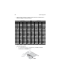
•
3 System upgrade
Observe the population sequence illustrated in the table below
when installing a memory module.
Branch 0
Branch 1
DIMM A1 DIMMA2 DIMMB 1 DIMMB2 DIMMC1 DIMMC2 DIMMD1 DIMMD2
512 MB
512 MB
512 MB
512 MB
512 MB
512 MB
512 MB
512 MB
512 MB
512 MB
512 MB
512 MB
512 MB
512 MB
512 MB
512 MB
512 MB
512 MB
512 MB
512 MB
512 MB
1 GB
1 GB
1 GB
1 GB
1 GB
1 GB
1 GB
1 GB
1 GB
1 GB
1 GB
1 GB
1 GB
1 GB
1 GB
1 GB
1 GB
1 GB
1 GB
1 GB
1 GB
2 GB
2 GB
2 GB
2 GB
2 GB
2 GB
2 GB
2 GB
2 GB
2 GB
2 GB
2 GB
2 GB
2 GB
2 GB
2 GB
2 GB
2 GB
2 GB
2 GB
2 GB
The installation sequence listed in the above table is illustrated in
the following figures.
•
In a minimum memory configuration, the FBD should be
installed in the DIMMA1 slot.
57
•
Install FBD pair upgrades in the following sequence:
– First FBD pair: DIMMA1 and DIMMB1 slots
– Upgrade 1: DIMMC1 and DIMMD1 slots
– Upgrade 2: DIMMA2 and DIMMB2 slots
– Upgrade 3: DIMMC2 and DIMMD2 slots
To remove an FBD:
Important: Before removing an FBD, make sure to back up all
important system files. Also, note that FBDs should be removed
in pairs.
1
Perform the pre-installation instructions described on page 37.
2
Lay the server on its side (components showing).
3
Remove the air duct to access to the FBD slots.
(1) Remove the three screws that secure the air duct.
(2) Detach the air duct from the heat sink-fan.
58
4
3 System upgrade
Remove the FBD.
(1) Press the holding clips on both sides of the socket outward to
release the DIMM.
(2) Gently pull the DIMM upward to remove it from the socket.
5
If you intend to install a new FBD, proceed to the next section for
related procedure, otherwise reinstall the air duct, then observe
the post-installation instructions described on page 38.
To install an FBD:
1
Perform steps 1 through 3 of the previous section.
2
Select an empty FBD slot.
3
If necessary, open the holding clips of the selected FBD slot.
4
Remove the new FBD from its protective packaging, handling it by
the edges.
5
Install the FBD.
(1) Align the FBD so that the notch on the slot fits the keyed edge
of the module, then press the module at both ends to seat it
fully into the slot.
If you insert an FBD but it does not fit easily into the slot, you
have inserted it incorrectly. Reverse the orientation of the
module and insert it again.
59
(2) Firmly press the holding clips inward to lock the FDB in place.
If the holding clips do not close, the FBD is not properly
inserted.
6
Reinstall the air duct.
7
Observe the post-installation instructions described on page 38.
The system automatically detects the amount of memory installed.
Run the BIOS setup to view the new value for total system memory
and make a note of it.
60
3 System upgrade
Installing an expansion card
This section explains how to install an expansion card.
I/O interface
Altos G540 has six PCI bus slots with of three separate bus segments,
namely:
•
PCI-E 1, PCI-E 4, and PCI-E 5 – PCI Express x8 slots
•
PCI-X 2 and PCI-X 3 – 64-bit, 66/100 MHz PCI-X slots
•
PCI7 – One 32-bit/33 MHz PCI bus slot
In addition to these six expansion slots, Altos G540 also has one
dedicated PCI-X expansion slot for the optional SAS controller board
(SODIMM1) slot.
To install an expansion card:
1
Perform the pre-installation instructions described on page 37.
2
If necessary, remove any cables that prevent access to the
processor sockets.
3
Locate an empty expansion slot that is compatible with the
specification of the card you intend to install.
4
Install the expansion card.
(1) Press the release latch of the slot cover opposite the selected
expansion slot.
(2) Pull out the slot cover and store it for reassembly later.
Caution: Do not discard the slot cover. If the expansion card is
removed in the future, the slot cover must be reinstalled to
maintain proper system cooling.
Remove the expansion card from its protective packaging,
handling it by the edges.
61
(3) Insert the card into the selected slot.
Make sure that the card is properly seated.
(4) Press the release latch to secure the card in place.
(5) Connect the necessary cables to the expansion card as
required.
5
Observe the post-installation instructions described on page 38.
When you turn on the system, the BIOS setup automatically
detects and assigns resources to the new device (applicable only to
Plug-and-Play expansion cards).
62
3 System upgrade
Installing the SAS controller board
If you intend to install a SAS hard drive, you need to first install the
LSI 1068 SAS controller board option.
To install the SAS controller board:
1
Perform the pre-installation instructions described on page 37.
2
Locate the SODIMM slot. If necessary, remove any cables that
prevent access to it.
3
Remove the SAS controller board from its protective packaging,
handling it by the edges.
4
Install the SAS controller board.
(1) Align then insert the gold-lined edge of the board into the
SODIMM slot.
(2) Firmly press the board down to seat it properly.
(3) Secure the board with the one screw.
5
Observe the post-installation instructions described on page 38.
When you turn on the system, the BIOS setup automatically
detects and assigns resources to the new device.
For information on how to install a SAS HDD, go to page 45.
63
Installing the BMC module
The optional BMC module allows system administrators to manage the
Altos G540 system remotely over a network.
To install the BMC module:
1
Perform the pre-installation instructions described on page 37.
2
Locate the IPMB_6 slot. If necessary, remove any boards or cables
that prevent access to it.
3
If necessary, open the holding clips of the IPMB_6 slot.
4
Remove the BMC module from its protective packaging, handling
it by the edges.
5
Install the BMC module.
(1) Align the module so that the notch on the IPMB_6 slot fits the
keyed edge of the module, then press the module at both
ends to seat it fully into the slot.
When the module is properly installed, the holding clips will
automatically lock in place.
(2) Secure the module with the one screw.
6
Observe the post-installation instructions described on page 38.
64
3 System upgrade
Installing the ARMC/3 module
Remote system management just got easier with the new ARMC/3
module. The module provides high performance KVM (keyboardvideo-mouse) redirection and features a dedicated NIC port for faster
network access.
To install the ARMC/3 module:
1
Perform the pre-installation instructions described on page 37.
2
Locate the IPMB_6 slot. If necessary, remove any boards or cables
that prevent access to it.
3
If necessary, open the holding clips of the IPMB_6 slot.
4
Remove the ARMC/3 module from its protective packaging,
handling it by the edges.
5
Install the ARMC/3 module.
(1) Align the module so that the notch on the IPMB_6 slot fits the
keyed edge of the module, then press the module at both
ends to seat it fully into the slot.
When the module is properly installed, the holding clips will
automatically lock in place.
(2) Secure the module with the one screw.
65
6
Install the dedicated NIC port card.
(1) Press the release latch of the slot cover opposite the IPMB_6
slot.
The release latch highlighted in the figure below is for
illustration purpose only.
(2) Pull out the slot cover and store it for reassembly later.
Caution: Do not discard the slot cover. If the expansion card is
removed in the future, the slot cover must be reinstalled to
maintain proper system cooling.
(3) Insert the dedicated NIC port card into the selected slot.
Make sure that the card is properly seated.
(4) Press the release latch to secure the card in place.
(5) Connect the card’s LAN cable to the LAN1 connector of the
ARMC/3 module.
7
Observe the post-installation instructions described on page 38.
66
3 System upgrade
Installing a redundant power supply module
The Altos G540 supports two 610-watts hot-swap power supply
modules. The system ships out with only one power supply module
installed. You have the option to install a second module to provide
the system with a redundant power source. A redundant power
configuration enables a fully-configured system to continue running
even if one of the power supply module fails.
WARNING! To reduce the risk of personal injury or
damage to the equipment, the installation of power
supply modules should be referred to individuals who are
qualified to service server systems and are trained to deal
with equipment capable of generating hazardous energy
levels.
WARNING! To reduce the risk of personal injury from
hot surfaces, observe the thermal labels on each power
supply modules. You can also consider wearing
protective gloves.
WARNING! To reduce the risk of personal injury from
electric shock hazards, do not open the power supply
module. There are no serviceable parts inside the
module.
Caution! Electrostatic discharge can damage electronic
components. Make sure that you are properly grounded
before handling a power supply module.
67
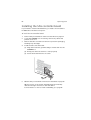
To install a hot-swap power supply module:
1
Detach the cover from the chassis.
Keep the cover for future reassembly.
2
Slide the module into the empty bay until you feel resistance, and
it locks into place.
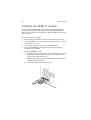
3
Verify that the power status indicators on the main power supply
and on the newly installed redundant power supply are
illuminated green.
68
3 System upgrade
4 System BIOS
This chapter gives information about the
system BIOS and discusses how to configure
the system by changing the settings of the
BIOS parameters.
71
BIOS overview
BIOS setup is a hardware configuration program built into the system's
Basic Input/Output System (BIOS). Since most systems are already
properly configured and optimized, there is no need to run this utility.
You will need to run this utility under the following conditions.
•
When changing the system configuration settings
•
When redefining the communication ports to prevent any conflicts
•
When modifying the power management configuration
•
When changing the password or making other changes to the
security setup
•
When a configuration error is detected by the system and you are
prompted ("Run Setup" message) to make changes to the BIOS
setup
Note: If you repeatedly receive Run Setup messages, the battery
may be bad. In this case, the system cannot retain configuration
values in CMOS. Ask a qualified technician for assistance.
BIOS setup loads the configuration values in a battery-backed
nonvolatile memory called CMOS RAM. This memory area is not part
of the system RAM which allows configuration data to be retained
when power is turned off.
Before you run the PhoenixBIOS Setup Utility, make sure that you have
saved all open files. The system reboots immediately after you close
the Setup.
Note: PhoenixBIOS Setup Utility will be simply referred to as
"Setup" or "Setup utility" in this guide.
The screenshots used in this guide display default system values.
These values may not be the same those found in your system.
72
4 System BIOS
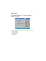
Entering BIOS setup
1
Turn on the server and the monitor.
If the server is already turned on, close all open applications, then
restart the server.
2
During POST, press F2.
If you fail to press F2 before POST is completed, you will need to
restart the server.
The Setup Main menu will be displayed showing the Setup’s menu
bar. Use the left and right arrow keys to move between selections
on the menu bar.
BIOS setup primary menus
The tabs on the Setup menu bar correspond to the six primary BIOS
Setup menus, namely:
•
Main
•
Advanced
•
Security
•
Server
•
Boot
•
Exit
In the descriptive table following each of the menu screenshots,
settings in boldface are the default and suggested settings.
73
BIOS setup navigation keys
Use the following keys to move around the Setup utility.
•
Left and Right arrow keys – Move between selections on the
menu bar.
•
Up and Down arrow keys – Move the cursor to the field you
want.
•
PgUp and PgDn keys – Move the cursor to the previous and next
page of a multiple page menu.
•
Home – Move the cursor to the first page of a multiple page
menu.
•
End – Move the cursor to the last page of a multiple page menu.
•
+ and - keys – Select a value for the currently selected field (only if
it is user-configurable). Press these keys repeatedly to display each
possible entry, or the Enter key to choose from a pop-up menu.
Note: Grayed-out fields are not user-configurable.
•
Enter key – Display a submenu screen.
Note: Availability of submenu screen is indicated by a (>).
•
Esc – If you press this key:
•
On one of the primary menu screens, the Exit menu displays.
•
On a submenu screen, the previous screen displays.
•
When you are making selections from a pop-up menu, closes
the pop-up without making a selection.
•
F1 – Display the BIOS setup General Help panel.
•
F9 – Press to load default system values.
•
F10 – Save changes made the Setup and close the utility.
74
4 System BIOS
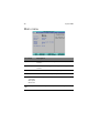
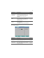
Main menu
Parameter
Description
System Time
Set the system time following the hour-minute-second
format.
System Date
Set the date following the weekday-month-day-year
format.
BIOS Version
Version number of the BIOS setup utility
BIOS Date
Date when the BIOS setup utility was created
Processor
CPU Type
Technical specifications for the installed processor
CPU Speed
CPU Count
Total Memory
Size
Total size of system memory detected during POST
75
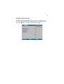
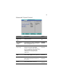
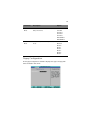
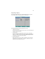
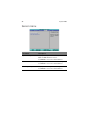
Advanced menu
The Advanced menu display submenu options for configuring the
function of various hardware components. Select a submenu item,
then press Enter to access the related submenu screen.
76
4 System BIOS
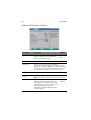
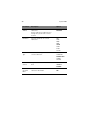
Advanced Processor Options
Parameter
Description
Option
Processor Retest
Select whether to delete the historical
processor data log. Processor(s) will be
retested on the next boot-up.
Yes
No
CPU Type
Processor model name
CPU Speed
The processor speed is the speed at which a
microprocessor executes instructions. Clock speeds are
expressed in megahertz (MHz), with 1 MHz being equal
to 1 million cycles per second. The faster the clock, the
more instructions the CPU can execute per second.
Processor CPUID
Processor ID number
Processor L2
Cache
Processor second-level cache size detected during POST
Note: This field is not shown on the above screenshot.
Hyperthreading
Select whether to enable the Intel HyperThreading (HT) Technology function. HT
enables the host operating system to view
a single physical processor to appear as two
logical processors. This can boost
performance in OS and applications that
are HT-compliant.
Enabled
Disabled
77
Parameter
Description
Option
Intel
Virtualization
Technology
Select whether to enable the Intel
Virtualization Technology function. VT
allows a single platform to run multiple
operating systems in independent
partitions.
Enabled
Disabled
C1 Enhanced
Mode
Select whether to enable the C1 Enhanced
mode for the processor. If enabled, all
logical processors in a physical processor
will run in a C1 state.
Enabled
CPU Cache
Control
Set which processor cache functions to run during
system debugging.
Press Enter to access the related submenu.
Disabled
CPU Cache Control
Parameter
Description
Option
Hardware
Prefetcher
Select whether to enable the speculative
prefetch unit of the processor.
Enabled
Disabled
Adjacent Cache
Line Prefetch
When enabled, cache lines are fetched in
pairs. When disabled, only the required
cache line is fetched.
Enabled
Disabled
78
4 System BIOS
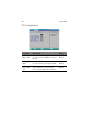
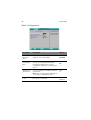
Memory Configuration
Parameter
Description
Option
Extended
Memory
Total size of extended memory detected during POST
DIMM Group
#1 - 8 Status
The size of memory installed on each of the FBD slots.
Memory Retest
Select whether to delete the
historical memory data log. System
memory will be retested on the next
boot-up.
Yes
No
Extend RAM
Setup
Select whether to enable extended
memory testing during boot-up.
Enabled
Memory Branch
Mode
Select the type of memory branch
mode to employ.
Sequential
Disabled
Interleave
Mirror
Single Channel 0
Branch 0/1 Rank
Sparing
Select whether to enable sparing for
the selected memory branch.
Enabled
Disabled
79
Advanced Chipset Control
Parameter
Description
Option
Advanced
Multimedia
Timer
Select whether to enable the system
multimedia timer.
Yes
No
Crystal Beach
Configure
Enable
Select whether to enable configuration
/memory mapped access to the Crystal
Beach Configuration space.
Enabled
I/O Acceleration
Technology
Select whether to enable the Intel
Acceleration Technology (I/OAT)
function. It addresses all segments of
the server I/O bottleneck problem using
TCP/IP and without requiring any
modification of existing or future
applications.
Enabled
Disabled
Wake On LAN/
PME
Select whether to wake up the system
when a LAN or PME event is detected.
Enabled
Wake On Ring
Select whether to wake up the system
when an incoming call is detected on
the modem.
Enabled
Disabled
Wake On RTC
Alarm
Select whether to wake up the system
when an RTC alarm is detected.
Enabled
Disabled
Disabled
Disabled
80
4 System BIOS
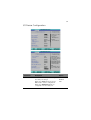
PCI Configuration
Parameter
Description
Option
PCI Slot 1 - 6
Option ROM
When enabled, this setting will initialize
the device expansion ROM for the related
PCI slot.
Enabled
Disabled
SAS Option
ROM
When enabled, this setting will initialize
the SAS controller board expansion ROM.
Enabled
LAN 1/2
Option ROM
Scan
Select whether to enable the selected
onboard LAN device. When enabled,
device expansion ROM will be initialized.
Enabled
Disabled
Disabled
81
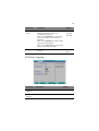
I/O Device Configuration
Parameter
Description
Option
Serial Port A/B
When enabled allows you to configure
the serial port settings.
When set to Auto allows the server’s
BIOS or OS to select a configuration.
Enabled
Disabled
When set to Disabled, displays no
configuration for the serial port.
Auto
82
4 System BIOS
Parameter
Description
Option
Base I/O address
Base I/O address and IRQ setting for the
selected serial port
3F8/IRQ4
2F8/IRQ3
3E8/IRQ4
2E8/IRQ3
Parallel Port
Mode
When enabled allows you to configure
the parallel port settings.
Enabled
Sets the operation mode for the
parallel port.
When set to Bi-Directional, allows
normal speed operation in a two way
mode.
Output only
Bi-Directional
Disabled
EPP
ECP
When set to EPP (Enhanced Parallel
Port), allows bi-directional parallel port
operation at maximum speed.
When set to ECP (Extended Capabilities
Port), allows the parallel port to
operate in a bi-directional mode and at
a speed higher than the maximum data
transfer rate.
Base I/O
Address
Interrupt
Base I/O address of the parallel port
378
278
IRQ setting of the parallel port
IRQ5
IRQ7
PS/2 Mouse
Enable this parameter if you intend to
use a mouse or trackball with a PS/2
interface.
Enabled
Disabled
USB Controller
Enables or disables the onboard USB
controller.
Enabled
USB 2.0
Controller
Enables or disables the onboard USB
2.0 controller.
Enabled
Disabled
Legacy USB
Support
Enables or disables support for legacy
USB devices.
Enabled
Route Port 80h
Cycles to
Select which bus to set the route port
80h cycles on.
PCI
Disabled
Disabled
LPC
83
Parameter
Description
Option
Parallel ATA
Select whether to enable support for
PATA devices.
Enabled
Disabled
Serial ATA
Select whether to enable support for
SATA devices.
Enabled
Select the native mode for the SATA
function.
Auto
Serial ATA
Select whether to set SATA/PATA
devices to legacy (Compatible) or
native (Enhanced) mode.
Selecting the Enhanced mode will
display the SATA RAID Enable field.
Enable this option to use the onboard
SATA RAID controller.
Compatible
Native Mode
Operation
SATA Controller
Mode Option
Disabled
Enhanced
IDE Configuration
The IDE Configuration submenu lets you define the parameter settings
related to the system hard drive(s).
84
4 System BIOS
I/O Channel 0/Secondary Master/Slave
Parameter
Description
Option
Type
Selects the drive type.
Auto
None
CD-ROM
ATAPI Removable
IDE Removable
User
Total Sectors
Total number of sectors available in the selected hard drive.
Maximum
Capacity
Maximum capacity of the selected hard drive.
Multi-Sector
Transfers
Set the multi-Sector transfer mode.
16 Sectors
Disabled
2 Sectors
4 Sectors
8 Sectors
LBA Mode
Control
Selects the hard disk drive translation
method. For drivers with more than
504 MB, LBA mode is necessary.
Enabled
32-bit I/O
Enables or disables the 32-bit data
transfer function
Enabled
Disabled
Disabled
85
Parameter
Description
Option
Transfer
Mode
Select a transfer mode to enhance hard
disk performance.
Fast PIO 4
Standard
Fast PIO 1
Fast PIO 2
Fast PIO 3
FPIO 3/DMA 1
FPIO 4/DMA 2
Ultra DMA
Mode
Selects DMA (Direct Memory Access)
mode.
Mode 6
Disabled
Mode 0
Mode 1
Mode 2
Mode 3
Mode 4
Mode 5
Floppy Configuration
The Floppy Configuration submenu displays the type of floppy disk
drive installed in the server.
86
4 System BIOS
Boot Configuration
Parameter
Description
Option
Boot-time
Diagnostic
Screen
Choose whether to display the boot-time
diagnostic screen during POST.
Enabled
Reset
Configuration
Data
Select whether to erase data in the section
of memory for ESCD (Extended System
Configuration Data) which stores the
configuration settings for non-PnP plug-in
devices.
Yes
Multiprocessor
Specification
Select the multiprocessor (MP) specification
revision level.
1.4
Disabled
No
1.1
Note: Some operating system will require a
1.1 setting for compatibility reasons.
POST Error
Pause
Select whether to pause POST when a
boot-up error is detected.
Enabled
Disabled
87
Parameter
Description
Option
After Power
Failure
Defines the power state to resume to after a
system shutdown that is due to an
interruption in AC power.
When set to Last State, the system will
return to the active power state prior to
shutdown.
Last State
Stay Off
Power On
When set to Stay Off, the system remains
off after power shutdown.
When set to Power On, the system will be
turned on from a power failure.
NumLock
Select the NumLock behavior during
boot-up.
On
Off
DMI Event Logging
Parameter
Description
Option
Event Log
Validity
Indicates the validity of the DMI event log.
Event Log
Capacity
Displays the space capacity allotted for the DMI event log.
88
4 System BIOS
Parameter
Description
Option
View DMI
Event Log
Press Enter to view the DMI (Desktop Management
Interface) event log.
To return to the DMI Event Logging submenu, click
Continue in the Event Log window.
Event
Logging
Select whether to allow logging of all
DMI events.
Enabled
ECC Event
Logging
Select whether to allow logging of ECC
events.
Enabled
Mark DMI
Events as
Read
Press Enter to view the DMI event log, then select an log
entry to mark as read.
Clear All
Event Logs
Select whether to delete all DMI event log
entries during the next system start-up.
Disabled
Disabled
Yes
No
89
Security menu
The Security menu allows you to safeguard and protect the system
from unauthorized use by setting up access passwords.
There are three types of passwords that you can set:
•
Supervisor password
Entering this password will allow the user to access and change all
settings in the Setup Utility.
•
User password
Entering this password will restrict a user’s access to the Setup
menus. To enable or disable this field, a supervisor password must
first be set. A user can only access and modify the System Time,
System Date, and Set User Password fields.
•
Power-on password
When the Password on Boot field is enabled, a password will be
required to boot up the server. To enable or disable this field, a
supervisor password must first be set.
90
4 System BIOS
Parameter
Description
Option
Supervisor
Password Is
This parameter indicates whether a
supervisor password has been assigned.
Clear
Enabled
User Password Is
This parameter indicates whether a user
password has been assigned.
Clear
Enabled
Set Supervisor
Password
Press Enter to configure the supervisor password.
Set User
Password
Press Enter to configure the user password.
Password On
Boot
Select Enabled to activate security check
during POST.
Disabled
Enabled
Setting a system password
1
Use the up/down keys to select a password parameter (Set
Supervisor Password or Set User Password), then press Enter.
A password box will appear.
2
Type a password then press Enter.
The password may consist of up to six alphanumeric characters
(A-Z, a-z, 0-9).
3
Retype the password to verify the first entry then press Enter
again.
4
Press F10.
5
Select Yes to save the new password and close the Setup Utility.
91
Changing a system password
1
Use the up/down keys to select a password parameter (Set
Supervisor Password or Set User Password), then press Enter.
2
Type the original password then press Enter.
3
Type a new password then press Enter.
4
Retype the password to verify the first entry then press Enter
again.
5
Press F10.
6
Select Yes to save the modified password and close the Setup
Utility.
Removing a system password
1
Use the up/down keys to select a password parameter (Set
Supervisor Password or Set User Password), then press Enter.
2
Enter the current password then press Enter.
3
Press Enter twice without entering anything in the new and
confirm password fields.
After doing this, the system automatically sets the related
password parameter to Clear.
92
4 System BIOS
Server menu
Parameter
Description
System Management
Displays basic system ID information, as well as
BIOS and BMC firmware versions.
Press Enter to access the related submenu.
Console Redirection
Displays console redirection-related settings.
Press Enter to access the related submenu.
Event Log Configuration
Displays DMI event log-related settings.
Press Enter to access the related submenu.
93
System Management
The System Management submenu is a simple display page for basic
system ID information, as well as BIOS and BMC firmware versions.
Items on this window are non-configurable.
Console Redirection
94
4 System BIOS
Parameter
Description
Option
COM Port
Address
Select whether to enable console
redirection.
Console redirection enables users to
manage the system from a remote
location.
Onboard COM A
Disabled
Baud Rate
Select the baud rate for console
redirection.
300
1200
2400
9600
19.2K
38.4K
57.6K
115.2K
Console
Type
Select a terminal type to be used for
console redirection.
VT100,
VT100 8bit
PC-ANSI 7bit
VT100+
VT-UTF8
Flow
Control
Assign control for the console redirection
flow.
None
Continue
C.R. After
POST
Select whether to enable console
redirection after POST.
On
Off
XON/OFF
CTS/RTS
95
Event Log Configuration
Parameter
Description
Option
Clear All Event
Logs
Press Enter then select whether to clear all entries in
the system event log.
Log POST Sys.
Event
Select whether to enable the BIOS event
log to be integrated in the system event
log.
Enabled
Disabled
96
4 System BIOS
Boot menu
The Boot menu allows you to set the drive priority during system
boot-up. BIOS setup will display an error message if the drive(s)
specified is not bootable.
By default, the server searches for boot devices in the following order:
1
Floppy disk drive
2
Optical disc drive
3
Removable device
4
Hard drive
97
Exit menu
The Exit menu displays the various options to quit from the BIOS setup.
Highlight any of the exit options then press Enter.
Parameter
Description
Exit Saving
Changes
Saves changes made and close the BIOS setup.
Exit Discarding
Changes
Discards changes made and close the BIOS setup.
Load Setup
Defaults
Loads the default settings for all BIOS setup parameters.
Setup Defaults are quite demanding in terms of
resources consumption. If you are using low-speed
memory chips or other kinds of low-performance
components and you choose to load these settings, the
system might not function properly.
Discard
Changes
Discards all changes made in the BIOS setup.
Save Changes
Saves changes made in the BIOS setup.
98
4 System BIOS
5 System
troubleshooting
This chapter provides possible solutions for specific
problems. If you cannot correct the problem,
contact your local Acer representative or
authorized dealer for assistance.
101
Resetting the system
Before going through in-depth troubleshooting, attempt first to reset
the system using one of the methods below.
Perform
Purpose
To do this
Soft boot
reset
To clear the system memory and reload
the operating system.
Press Ctrl+Alt+Del
Cold boot
reset
To clear the system memory, restart
POST, and reload the operating system.
This will halt power to all peripherals.
Press the system
power button off
and then on.
102
5 System troubleshooting
Initial system startup problems
Problems that occur at initial system startup are usually caused by an
incorrect installation or configuration. Hardware failure is a less
possible cause. If the problem you are experiencing is with a specific
application, see the "There is problem with the software program" section
on page 108.
103
Initial troubleshooting checklist
Use the checklist below to eliminate the possible cause for the problem
you’re encountering.
•
AC power is available at the wall outlet?
•
Is the power supply module properly installed?
•
Is the system power cord properly plugged into the power supply
module socket? and connected to a NEMA 5-15R outlet for
100-120 V or a NEMA 6-15R outlet for 200-240 V?
•
Are all peripheral cables correctly connected and secured?
•
Did you press the system power button to turn the server on
(power on indicator should be lit green)?
•
Are all device drivers properly installed?
•
Is hard disk drive(s) properly formatted and configured?
•
Are the BIOS configuration settings in the BIOS setup utility
correct?
•
Is the operating system properly loaded?
Refer to the operating system documentation.
•
Are all hardware components compliant with the tested
components lists?
•
Are all internal cables correctly connected and secured?
•
Are the processors fully seated in their mainboard sockets?
•
Are all standoffs in the proper location and not touching any
components, causing a potential short?
•
Are all add-in expansion cards fully seated in their mainboard
slots?
•
Are all system jumpers correctly set?
•
Are all switch settings on add-in boards and peripheral devices
correct?
To check these settings, refer to the manufacturer’s
documentation that comes with them. If applicable, ensure that
there are no conflicts (e.g., two add-in boards sharing the same
interrupt.
104
5 System troubleshooting
Hardware diagnostic testing
This section provides a detailed approach to identifying a hardware
problem and its cause.
Checking the boot-up status
Caution: Before disconnecting any peripheral cables from the
server, turn off the system and any peripheral devices. Failure to
do so can cause permanent damage to the system and/or the
peripheral device.
1
Turn off the system and all external peripheral devices.
2
Disconnect all peripheral devices from the system, except for the
keyboard and the display monitor.
3
Make sure the system power cord is plugged into a properly
grounded AC outlet and in the power supply module cord socket.
4
Make sure the display monitor and keyboard are correctly
connected to the system.
5
Turn on the display monitor.
6
Set the display brightness and contrast controls to at least two
thirds of their maximum range.
Refer the documentation that came with your display monitor.
7
If the operating system normally loads from the hard drive, make
sure there is no diskette in floppy drive and no disc in the
DVD-ROM drive.
8
If the power indicator is lit, attempt to boot from a floppy diskette
or from a disc.
9
Turn on the system.
If the power indicator did not light up, see “Power indicator does
not light” on page 106.
105
Verifying the condition of the storage devices
As POST determines the system configuration, it tests for the presence
of each mass storage device installed in the system. As each device is
checked, its activity indicator should turn on green briefly. Check the
activity indicators for the hard drive(s), DVD-ROM drive, floppy drive,
and any other 5.25-inch device you may have installed.
If any of these indicators fail to light up, refer to related problems
listed in the “Specific problems and corrective actions” section.
Confirming loading of the operating system
Once the system boots up, the operating system prompt appears on
the screen. The prompt varies according to the operating system. If
the operating system prompt does not appear, see "No characters
appear the display monitor" on page 109.
106
5 System troubleshooting
Specific problems and corrective
actions
Listed below are specific problems that may arise during the use of
your server and their possible solutions.
Power indicator does not light.
Do the following:
•
Make sure the power supply module is properly installed.
•
Make sure the power cord is connected correctly.
•
Make sure that the wall outlet has power. Test it by plugging
another device.
•
Make sure the power indicator on the front panel is lit up green.
•
Remove all add-in cares and see if the system boots.
If reboot is successful, install the cards back in one at a time with a
reboot between each addition to determine if one of them is
causing the problem.
•
Make sure that you have properly installed system compliant
memory modules, and that there populated according to the
system guidelines.
•
Make sure that you have installed system compliant processors,
and that there populated according to the system guidelines.
FDD activity indicator does not light.
Do the following:
•
Make sure the FDD data and power cables are properly connected.
•
Check that relevant switches and jumpers for the FDD are set
correctly.
•
Check that FDD is properly configured.
•
Run the BIOS setup utility and make sure the Legacy Diskette A
field under the Advanced | Floppy Configuration menu is set as
1.44/1.25 MB 3 1/2.
107
HDD activity indicator does not light.
Do the following:
•
Make sure the data and power cables are connected correctly.
•
Check that relevant switches and jumpers on the hard drive and on
the backplane board (for hot-plugs HDD) are set correctly.
DVD drive activity indicator does not light.
Do the following:
•
Make sure the IDE and power cables are properly connected.
•
Check that relevant switches and jumpers on the drive are set
correctly.
•
Check that the drive is properly configured.
DVD tray cannot be ejected.
Insert the tip of a paperclip into the small hole on the DVD drive.
Slowly pull the tray out from the drive until the tray is fully extended.
DVD drive cannot read a disc.
Do the following:
•
Make sure you are using the correct type of disc.
•
Make sure the disc is properly seated in the drive.
•
Make sure the disc is unscratch and free of any contaminant.
•
Make sure the drive’s IDE and power cables are properly
connected.
Newly installed memory modules are not detected.
Do the following:
•
Make sure the memory modules specifications comply with the
system requirements.
•
Make sure the memory modules have been populated according
to the system guidelines.
•
Make sure the memory modules are properly installed on their
mainboard slots.
108
5 System troubleshooting
Network connection indicators do not light.
Do the following:
•
Check the cabling and network equipment to make sure that there
are in proper condition.
•
Reinstall the network drivers.
•
Try another port or hub on the switch.
Network activity indicators do not light.
Do the following:
•
Make sure the correct network drivers are loaded on the system.
•
Network might be idle.
Peripheral device connected to a USB port does not work.
Do the following:
•
Reduce the number of external devices connected to a USB hub.
•
Refer to the documentation that came with the device.
There is problem with the software program.
Do the following:
•
Verify that the software is properly configured for the system.
Refer to the software installation and operation documentation
for instructions on setting up and using the software.
•
Try a different version of the software to see if the problem is with
the copy you are using. If the other version runs correctly on the
system, contact your vendor about the defective software.
109
No characters appear on the display monitor.
Check the following:
•
Is the keyboard functioning? Test it by turning the Num Lock
function on and off to check if the Num Lock indicator lights up.
•
Is the display monitor plugged in and turned on? If you are using
a switch box, is it switched to the correct system?
•
Are the brightness and contrast controls on the video monitor
properly adjusted?
•
Is the display monitor signal cable properly connected?
•
Does this display monitor work correctly if plugged into a
different system?
•
Remove all add-in cares and see if the system boots.
If reboot is successful, install the cards back in one at a time with a
reboot between each addition to determine if one of them is
causing the problem.
•
Make sure that you have properly installed system compliant
memory modules, and that there populated according to the
system guidelines.
•
Make sure that you have installed system compliant processors,
and that there populated according to the system guidelines.
If you are using an add-in video controller card, do the following:
1
Verify that the display monitor works using the onboard video
controller.
2
Verify that the add-in video controller card is fully seated in its slot.
3
Reboot the system for the changes to take effect.
4
If there are still no characters on the screen after you reboot the
system, reboot it again.
Take note of the beep codes emitted during POST. This
information may be required if you seek technical assistance.
If POST does not emit any beep code and characters still does not
appear, the display monitor or the video controller may be
defective. Contact your local Acer representative or authorized
dealer for technical assistance.
110
5 System troubleshooting
Appendix A: Server
management tools
This appendix gives an overview of the
different server management tools
supported by your server.
113
Server management overview
The server management tools supported by the Altos G540 system is
listed in the table below.
Tool
Function
PhoenixBIOS Setup
Utility
Use this tool to configure the different hardware
components and system functions (memory,
processor, and security settings). Go to the BIOS
setup chapter on page 69 for details.
ASM (Acer Server
Management)
This utility allows a system administrator to
remotely manage the server in a network
environment through a single management
station. For detailed instructions on how to
install and use this utility, refer to the user
documentation accompanying it.
Onboard SATA RAID
Configuration Utility
Use any of these utilities to configure RAID for
the system hard drives. The two LSI utilities are
only available when their corresponding SAS
controller board option is installed in the server.
Proceed to the next section for instructions on
how to use these utilities.
LSI 1068 SAS
Configuration Utility
LSI MegaRAID SAS RAID
Configuration Utility
Note: Support for the LSI 1068 SAS Configuration Utility may not be
available for all system releases.
114
Appendix A: Server management tools
RAID configuration utilities
RAID option for the Altos G540 system is provided through either the
onboard SATA controller or through an external controller board
option (LSI 1068 SAS controller or LSI MegaRAID SAS RAID controller).
Caution: Creating a RAID volume erases all data previously saved
in the hard drives. Make sure that you back up important files
before starting a RAID configuration process.
Onboard SATA RAID Configuration Utility
This section explains how to create a RAID 1 volume using the onboard
SATA controller.
To enable the onboard SATA RAID controller:
1
Turn on the server and the monitor.
If the server is already turned on, close all open applications, then
restart the server.
2
During POST, press F2 to access the BIOS Setup Utility.
3
Select the Advanced | I/O Device Configuration submenu.
4
Change the setting of the SATA Controller Mode Option field from
Compatible to Enhanced.
5
Change the setting of the SATA RAID Enable field from Disabled to
Enabled.
6
Press F10.
7
Select Yes to save the new SATA RAID settings and close the Setup
Utility.
115
To initialize the Onboard SATA RAID Configuration Utility:
Note: There must be more than two SATA hard drives installed in
the system, otherwise the Intel Matrix Storage Manager option
ROM will be disabled.
1
Turn on the server and the monitor.
2
During POST, press Ctrl-I on the Intel Matrix Storage Manager
option ROM prompt.
To create a RAID 1 volume:
1
On the Onboard SATA RAID Configuration Utility, select
1. Create RAID Volume under the Main Menu, then press Enter.
2
Specify a name for the new RAID volume, then press Enter.
3
Use the Up and Down arrow keys to select RAID 1 (Mirror) for
the RAID level, then press Enter.
4
Use the space bar to select the drives that you want to add into the
array, then press Enter.
This step is only applicable for systems with more than two hard
drives installed.
5
Press Enter to accept the RAID 1 volume capacity.
6
Press Enter, then Y to start creating the new RAID 1 volume.
Once the new RAID 1 volume is created, it’ll be listed under the
Disk/Volume Information.
7
Revert to the Main Menu and select 4. Exit the MAIN MENU.
Proceed to the installation of the operating system. Refer to the
user documentation that came with your OS for related
instructions.
116
Appendix A: Server management tools
LSI 1068 SAS Configuration Utility
This section explains how to create a RAID 1 volume when the LSI 1068
SAS controller board is installed.
To initialize the LSI Logic Config Utility:
1
Turn on the server and the monitor.
If the server is already turned on, close all open applications, then
restart the server.
2
During POST, press Ctrl-C on the SAS BIOS prompt.
To load the factory default RAID setting:
1
On the LSI Logic Config Utility, press Alt-N to display Global
Properties.
2
Select Restore Defaults, then press Enter.
3
Press Esc, then select Save changes then exit this menu.
4
Select SAS1068, then press Enter.
5
Select Advanced Adapter Properties, then press Enter.
6
Select Restore Defaults, then press Enter.
7
Press Esc twice, then select Save changes then exit this menu.
To create a RAID 1 volume with a hot spare disk:
1
On the LSI Logic Config Utility, click SAS1068, then press Enter.
2
Select RAID Properties, then press Enter.
3
Select Create IM Volume, then press Enter.
4
Move the cursor to the RAID Disk column.
5
Press the space bar to change the setting from No to Yes.
The Drive Status will be marked as Primary.
6
Move the cursor to another disk.
7
Press the space bar to change the setting from No to Yes.
The Drive Status will be marked as Secondary.
117
8
Move the cursor to the Hot Spr column and select another disk.
9
Press the space bar to change the setting from No to Yes.
The Drive Status will be marked as Hot Spare.
10 Press C, then select Save changes then exit this menu.
11 Press Esc twice and select Exit the Configuration Utility and
Reboot.
Proceed to the installation of the operating system. Refer to the
user documentation that came with your OS for related
instructions.
LSI MegaRAID SAS RAID Configuration Utility
This section explains how to create a RAID 1 volume when the LSI
MegaRAID SAS RAID controller board is installed.
To initialize the LSI MegaRAID SAS RAID Configuration Utility:
1
Turn on the server and the monitor.
If the server is already turned on, close all open applications, then
restart the server.
2
During POST, press Ctrl-H on the RAID BIOS prompt.
After POST completion, the Adapter Selection window will appear.
3
Click Start to launch the Configuration menu.
To load the factory default RAID setting:
1
On the Configuration menu, select Adapter Properties to display
the current adapter settings.
2
Click Next to change the adapter setting.
3
Change the setting of Set Factory Defaults from No to Yes, then
click Submit.
4
Press Ctrl+Alt+Del to reboot the server.
118
Appendix A: Server management tools
To create and initialize a RAID volume:
1
Access the Configuration menu.
2
Click Configuration Wizard.
3
Click Add Configuration, then click Next.
4
Click Custom Configuration, then click Next.
5
Use the Ctrl key to select the drives that you want to add into the
array.
6
After selecting the drives, click Accept DG, then Next.
7
Select the RAID Level you want to use.
8
Create the logical volume and specify its size on the Select Size
field, then click Accept.
9
After creating a logical volume on all of the RAID volume, click
Accept, then Yes to save the configuration.
10 Click Yes to initialize the new logical drives.
All the created logical drives will be listed.
11 Click on Home to revert to the Configuration menu.
12 Select Exit, then Yes.
13 Press Ctrl+Alt+Del to reboot the system.
Proceed to the installation of the operating system. Refer to the
user documentation that came with your OS for related
instructions.
To assign a hot spare disk:
1
Access the Configuration menu.
2
Under Physical Drives, select a free disk marked as UNCONF
GOOD.
3
Select Make Global Dedicated HSP or Make Dedicated HSP,
then click Go.
4
Click on Home to revert to the Configuration menu.
Under Physical Drives, the assigned hot spare disk is marked as
Hotsapare and highlighted in pink.
Appendix B: Rack mount
configuration
This appendix shows you how to set up the
Altos G540 server in a rack mount configuration.
121
Rack installation information
The Altos G540 server system can also be mounted in a rack-model
position. A rack mount kit is available for customers who want to
convert a tower-mounted system to rack-model design. To purchase a
rack mount kit, contact your local Acer representative or order directly
from http://www.acer.com/.
Rack installation precautions
Follow the rack manufacturer's safety and installation instructions for
proper rack installation.
The following additional rack safety installation measures should be
considered:
•
Anchor the equipment rack
The equipment rack must be anchored to an unmovable suitable
support to prevent the rack from falling over when one or more
systems are fully extended out of the rack assembly. You must also
consider the weight of any other devices installed in the rack
assembly. The equipment rack must be installed according to the
manufacturer's instructions.
•
Main AC power disconnect
You are responsible for installing an AC power disconnect for the
entire rack unit. This main disconnect must be readily accessible,
and it must be labeled as controlling power to the entire unit, not
just to the system(s).
•
Earth ground the rack installation
To avoid the potential for an electrical shock hazard, the rack
assembly itself must be suitably earth grounded, according to your
local regional electrical codes. This typically will require the rack
to have its own separate earth ground. We recommend you
consult your local approved electrician.
122
•
Appendix B: Rack mount configuration
Elevated operating ambient temperature
The maximum operating temperature of the system is 35°C (95°F).
Careful consideration should be given to installing the system in
an environment compatible with the 35°C (95°F) maximum
ambient temperature.
•
Reduced airflow
The amount of airflow required for the safe operation of the
equipment should not be compromised when installing the system
in a rack.
•
Mechanical loading
Exercise care when mounting the system in a rack to avoid any
accidents.
•
Circuit overloading
Appropriate consideration should be given when connecting the
supply circuit to the system to avoid any circuit overload. The
system name plate rating should be used when addressing
concerns about circuit overload.
Rack mount kit
The rack mount kit components and their respective function is listed
on the table below.
Component
Quantity
Usage
Mounting rails
2
Allows the server to slide in and out of the
rackmount for maintenance purposes.
Each mounting rail consists of the
following:
• Fixed outer rail. Attaches to system rack
with M6 x 13 screws.
• Inner rail. Attaches to the sides of the
server with M4 x 5 screws.
• Middle sliding piece has a steel ball
gearing to control server movement
from and into the rackmount.
123
Component
Quantity
Usage
Front brackets
2
Attach the mounting rails to the server.
Rear brackets
2
Side handles
2
Screw pack
Attached to the sides of the server.
Secures the different rack components.
Refer to the next section for details.
Screw types
The following screws are used in the assembly of the Altos G540 system
and bundled rack-mountable components.
Screw type
Quantity
Figure
Usage
M6 X 13
8
Install the mounting rails to the
rack.
M6 x 18
2
Secure the cable arm to the rack.
M6 cage nut
2
Install into the vertical rails of the
rack for cable arm support.
Distand
8
Install into the vertical rails of the
rack for server support.
M4 x 5
4
Secure the mounting rails to the
chassis.
U#6-32 x 6.4
6
• Secure the rack handles to the
chassis (4).
• Attach the cable arm to the
chassis (2).
124
Appendix B: Rack mount configuration
Vertical mounting hole pattern
The four vertical rails of the system rack contain mounting holes
arranged in a manner shown in the figure below.
The system occupies 5U in the rack. Count the U positions and hole
numbers from the bottom up.
The distance from the center of two holes with closer spacing to the
center of the next pair is equivalent to 1U.
Note: The unit of measurement used in this guide is "U"
(1U = 1.75 inches or 44.45 mm). The total sum of the heights of all
components in the rack measured in "U" cannot exceed the height
of the rack. For more information, refer to the documentation that
came with the system rack.
When installing components, you must start your measurement from
the center of the two holes with closer spacing. Otherwise, the screw
holes on the component may not match those on the rack.
125
Rack installation procedures
Preparing the server for rack installation
1
Remove the foot stands from the server.
(1) Lay the server on its side on a flat, stable surface.
(2) Use a flat-blade screwdriver to remove the stoppers securing
the foot stands to the chassis.
(3) Detach the foot stands from the server.
Store the foot stands and its toppers for future reassembly.
2
Expose the installation recess for the topside inner rail.
(1) Remove the two screws securing the recess cover on the
topside of the server.
(2) Detach the recess cover from the server.
126
3
Appendix B: Rack mount configuration
Remove the inner rails from the mounting rails.
(1) Extend the inner rail from the mounting rail until the rail
release latch is exposed.
(2) Depress the release latch (1) and slip the inner rail out (2).
Do the same thing to the other mounting rail.
4
Attach the rack handles and inner rails to the server.
(1) Align the screw holes on the rack handles with those on the
server.
(2) Secure the rack handles with two U#6-32 x 6.4 screws each.
(3) Insert the pegs on the server with the notches on the
mounting rails, then slide the mounting rails backward to seat
them properly.
(4) Secure the mounting rails to the server with two M4 x 5 screws
each.
127
Preparing the rack for server installation
1
Install eight distands into the vertical rails of the system rack.
2
Adjust the front bracket to the preferred length.
(1) Turn the captive thumbscrews counterclockwise to loosen
them.
(2) Slide the front bracket to the preferred length.
(3) Secure the front bracket in its preferred position by turning
the captive thumbscrews clockwise.
Do the same thing to the other front bracket.
128
3
Appendix B: Rack mount configuration
Install the mounting rails to the system rack.
(1) Install the mounting rails to the rack by using four M6 x 13
screws for each rail.
(2) Extend the middle sliding piece of each mounting rail forward
until you hear an audible click.
129
Installing the server in the system rack
Warning! To avoid injury, care should be taken when
pressing the inner rail release latches and sliding the
component into the rack. It also recommended that two or
more people help in installing the server to the rack to
minimize the chances of accidents.
1
Press the release latch on both sides of the rack mounting rails.
2
Carefully align the inner rails attached to the server with the fully
extended mounting rails on the rack, then push the server into the
rack until you hear an audible click.
130
Appendix B: Rack mount configuration
Installing the cable arm option
The cable arm option allows you to tie-wrap all cables to and from the
system. As you slide the system in and out of the rack, the cable arm
collapses and extends, keeping the cables untangled and attached to
the system.
To install the cable arm:
1
Attach the cable arm to the rear panel using two U#6-32 x 6.4
screws.
2
Install two M6 cage nuts into the vertical rail to which the cable
arm is to be attached.
131
3
Extend the cable arm enough to attach it to the installed M6 cage
nuts, and secure it with two M6 x 18 screws.
4
Arrange the server cables.
(1) Connect the power, peripheral and networking cables into
their appropriate ports on the rear panel.
Go to page 28 for related instructions.
(2) Secure all server cables to the cable arm using the cable
clamps.
132
Appendix B: Rack mount configuration
133
Index
Numerics
5.25 inch device bays
install 48
location 9
supported devices
4
A
Acer EasyBUILD
scope 31
using 31
air duct
location 13
remove 57
ARMC/3 module
board layout 20
install 64
mainboard slot 16
specifications 7
B
backplane board
board layout 17
cable connections 42
Basic Input/Output System, see BIOS
71
BIOS
CMOS RAM 71
configure 72
overview 71
BIOS Setup
Advanced Chipset Control 79
Advanced menu 75
Advanced Processor Options 76
Boot Configuration 86
Boot menu 96
Console Redirection 93
CPU Cache Control 77
DMI Event Logging 87
enter Setup 72
Event Log Configuration 95
Exit menu 97
Floppy Configuration 85
I/O Device Configuration 81
IDE Configuration 83
Main menu 74
Memory Configuration 78
navigation keys 73
PCI Configuration 80
Security menu 89
Server menu 92
System Management 93
BMC module
board layout 19
install 63
mainboard slot 16
specifications 7
boot-time diagnostic screen 86
boot-up sequence 96
C
cable arm 130
CMOS battery 16
CMOS clear jumper
CMOS RAM 71
console redirection
16
93
D
DMI event log
BIOS settings 87
view 88
DVD-ROM drive
location 9
remove 48
troubleshooting 107
E
easy-swap HDD
cable connections 47
install 47
electrostatic discharge, see ESD precautions 37
environmental specifications
humidity 6
system cooling 6
temperature 6
vibration 6
expansion card
I/O interface 60
install 60
PCI slots 16
134
F
L
floppy disk drive
BIOS setting 85
location 10
mainboard connector 16
replace 49
troubleshooting 106
front bezel
remove 40
view 8
front panel 9
LAN ports
location 12
network connection indicator
22
network speed indicator 22
troubleshooting 108
LED indicators
front panel 21
HDD carrier 22
LAN port 22
power supply module 23
LSI Logic Config Utility 116
LSI MegaRAID SAS RAID
Configuration Utility 117
H
hard drive
activity indicator, location 9
activity indicator, status 21
BIOS settings 83
install, easy-swap 47
install, hot-plug 45
RAID configuration 114
troubleshooting 107
hardware monitor 15
hardware options
media storage 7
redundant modules 7
server management 7
hardware upgrade
options 7
procedures 37
HDD cage
bay location 10
install 41
remove 44
remove cover 43
heat sink fan
cable connector, CPU1 15
cable connector, CPU2 15
install 53
remove 51
thermal grease 52
hot-plug HDD
activity indicator, location 10
activity indicator, status 22
cable connections 42
install 45
I
I/O port connections
28
M
mechanical specifications
chassis 6
mainboard 6
media storage
specification 4
upgrade option 7
memory
BIOS settings 78
configuration guidelines
install 58
population order 56
remove 57
troubleshooting 107
monitor port 11
55
N
north bridge
15
O
Onboard SATA RAID Configuration
Utility 114
operating system
configure 31
support 5
P
parallel port
BIOS setting 82
location 11
PCI bus slots
BIOS settings 80
overview 60
135
PhoenixBIOS Setup Utility, see BIOS
Setup 72
POST
error pause 86
turn-on procedure 29
power
boot-up problems 30
boot-up sequence 96
button, location 10
cable socket 11
indicator, location 9
indicator, status 21
troubleshooting 106
turn off 33
turn on 29
power off
via hardware 33
via software 33
power supply module
fault indicator, description 23
fault indicator, location 12
install 66
redundant bay 13
release latch 11
status indicator, description 23
status indicator, location 12
power-on password 89
power-on self-test, see POST 29
processor
BIOS information 74
BIOS settings 76
configuration guidelines 50
remove 51
sockets location 15
upgrade 50
PS/2 keyboard port 11
PS/2 mouse port 11
R
rack installation
cable arm 130
mounting hole pattern
precautions 121
procedures 125
rack mount kit 122
screw types 123
124
RAID configuration
LSI Logic Config Utility 116
LSI MegaRAID SAS RAID
Configuration Utility 117
Onboard SATA RAID
Configuration Utility 114
rear panel 11
S
SAS controller board
board layout 18
install 62
mainboard slot 16
security keylock 8
serial port
BIOS setting 81
location 11
server management
specification 5
tools 113
upgrade options 7
side panel
release button 8
remove 39
south bridge 16
specification
chipset 3
environmental 6
hardware monitoring 5
I/O ports 5
mechanical 6
media storage 4
memory 3
networking 4
operating system 5
PCI interface 4
power supply 5
processor 3
server management 5
system fan 5
video controller 4
status/fault indicator
description 21
location 9
supervisor password 89
system boards
ARMC/3 module 20
backplane board 17
BMC module 19
136
mainboard 14
SAS controller board 18
system fan
cable connectors 15
location 13
system jumpers
BIOS recovery 16
clear CMOS 16
clear password 16
system passwords
change 91
power-on password 89
remove 91
set 90
supervisor password 89
user password 89
system reset
cold boot 101
soft boot 101
system setup
connect peripherals 28
install OS 31
pre-installation
requirements 27
turn on system 29
system upgrade
5.25 inch storage device 48
ARMC/3 module 64
BMC module 63
ESD precautions 37
expansion card 60
hard drive 41
installation precautions 37
memory 55
post-installation instructions 38
preinstallation instructions 38
processor 50
redundant power supply
module 66
SAS controller board 62
T
thermal grease 52
troubleshooting
display problems 109
DVD-ROM drive problems 107
FAQ 106
FDD problem 106
hardware diagnostics 104
HDD problem 107
initial checklist 103
initial startup problems 102
memory problem 107
network problems 108
power indicator problem 106
software program problem 108
system reset 101
USB device problems 108
U
UID switch 12
unit identification, see UID switch 12
USB ports
front 10
rear 12
troubleshooting 108
user password 89
W
wake-up events
Wake on LAN 79
Wake on Ring 79
Wake on RTC alarm
79
Z
ZCR
compatible PCI-X slot 17
SAS ZCR option 17
Zero Channel RAID, see ZCR 17