1
BB!H621!.!FO/cppl!!Qbhf!j!!Xfeoftebz-!Kbovbsz!9-!3114!!21;63!BN
Acer Altos G510 series
User’s guide
BB!H621!.!FO/cppl!!Qbhf!jj!!Xfeoftebz-!Kbovbsz!9-!3114!!21;63!BN
Copyright © 2002 Acer Incorporated
All Rights Reserved.
Acer Altos G510 series
User’s guide
2nd Issue: January 2002
Changes may be made periodically to the information in this publication without obligation
to notify any person of such revision or changes. Such changes will be incorporated in new
editions of this manual or supplementary documents and publications. This company makes
no representations or warranties, either expressed or implied, with respect to the contents
hereof and specifically disclaims the implied warranties of merchantability or fitness for a
particular purpose.
Record the model number, serial number, purchase date, and place of purchase information in
the space provided below. The serial number and model number are recorded on the label
affixed to your computer. All correspondense concerning your unit should include the serial
number, model number, and purchase information.
No part of this publication may be reproduced, stored in a retrieval system, or transmitted, in
any form or by any means, electronic, mechanical, photocopy, recording, or otherwise,
without the prior written permission of Acer Incorporated.
Model Number : _________________________________
Serial Number: ___________________________________
Purchase Date: ___________________________________
Place of Purchase: ________________________________
Acer and the Acer logo are registered trademarks of Acer Inc. Other company’s product
names or trademarks are used herein for identification purposes only and belong to their
respective companies.
BB!H621!.!FO/cppl!!Qbhf!jjj!!Xfeoftebz-!Kbovbsz!9-!3114!!21;63!BN
iii
Notices
FCC notice
Class A devices do not have an FCC logo or FCC IDE on the label. Class B devices
have an FCC logo or FCC IDE on the label. Once the class of the device is
determined, refer to the following corresponding statement.
Class B equipment
This device has been tested and found to comply with the limits for a Class B
digital device pursuant to Part 15 of the FCC Rules. These limits are designed to
provide reasonable protection against harmful interference in a residential
installation. This device generates, uses, and can radiate radio frequency
energy, and if not installed and used in accordance with the instructions, may
cause harmful interference to radio communications.
However, there is no guarantee that interference will not occur in a particular
installation. If this device does cause harmful interference to radio or television
reception, which can be determined by turning the device off and on, the user
is encouraged to try to correct the interference by one or more of the following
measures:
•
Reorient or relocate the receiving antenna
•
Increase the separation between the device and receiver
•
Connect the device into an outlet on a circuit different from that to which
the receiver is connected
•
Consult the dealer or an experienced radio/television technician for help
BB!H621!.!FO/cppl!!Qbhf!jw!!Xfeoftebz-!Kbovbsz!9-!3114!!21;63!BN
iv
Notice: Shield cables
All connections to other computing devices must be made using shielded cables
to maintain compliance with FCC regulations.
Notice: Peripheral devices
Only peripherals (input/output devices, terminals, printers, etc.) certified to
comply with the Class A or Class B limits may be attached to this equipment.
Operation with noncertified peripherals is likely to result in interference to
radio and TV reception.
Caution! Changes or modifications not expressly approved by
the manufacturer could void the user’s authority, which is granted
by the Federal Communications Commission, to operate this
server.
Use conditions
This part complies with Part 15 of the FCC Rules. Operation is subject to the
following two conditions: (1) this device may not cause harmful interference,
and (2) this device must accept any interference received, including interference
that may cause undesired operation.
Notice: Canadian users
This Class A/Class B digital apparatus meets all requirements of the Canadian
Interference-Causing Equipment Regulations.
Laser compliance statement
The CD-ROM drive in this server is a laser product. The CD-ROM drive’s
classification label (shown below) is located on the drive.
CLASS 1 LASER PRODUCT
CAUTION: INVISIBLE LASER RADIATION WHEN OPEN. AVOID EXPOSURE TO
BEAM.
BB!H621!.!FO/cppl!!Qbhf!w!!Xfeoftebz-!Kbovbsz!9-!3114!!21;63!BN
v
Important safety instructions
Read these instructions carefully. Save these instructions for future reference.
1
Follow all warnings and instructions marked on the product.
2
Unplug this product from the wall outlet before cleaning. Do not use
liquid cleaners or aerosol cleaners. Use a damp cloth for cleaning.
3
Do not use this product near water.
4
Do not place this product on an unstable cart, stand, or table. The product
may fall, causing serious damage to the product.
5
Slots and openings on the back or bottom side of the chassis are provided
for ventilation; to ensure reliable operation of the product and to protect
it from overheating, these openings must not be blocked or covered. The
openings should never be blocked by placing the product on a bed, sofa,
rug, or other similar surface. This product should never be placed near or
over a radiator or heat register, or in a built-in installation unless proper
ventilation is provided.
6
This product should be operated from the type of power indicated on the
marking label. If you are not sure of the type of power available, consult
your dealer or local power company.
7
Do not allow anything to rest on the power cord. Do not locate this
product where persons will walk on the cord.
8
If an extension cord is used with this product, make sure that the total
ampere rating of the equipment plugged into the extension cord does not
exceed the extension cord ampere rating. Also, make sure that the total
rating of all products plugged into the wall outlet does not exceed the fuse
rating.
9
Never push objects of any kind into this product through chassis slots as
they may touch dangerous voltage points or short out parts that could
result in a fire or electric shock. Never spill liquid of any kind on the
product.
10
Do not attempt to service this product yourself, as opening or removing
covers may expose you to dangerous voltage points or other risks. Refer all
servicing to qualified service personnel.
11
Unplug this product from the wall outlet and refer servicing to qualified
service personnel under the following conditions:
a
When the power cord or plug is damaged or frayed
b
If liquid has been spilled into the product
c
If the product has been exposed to rain or water
BB!H621!.!FO/cppl!!Qbhf!wj!!Xfeoftebz-!Kbovbsz!9-!3114!!21;63!BN
vi
d
If the product does not operate normally when the operating
instructions are followed. Adjust only those controls that are covered
by the operating instructions since improper adjustment of other
controls may result in damage and will often require extensive work
by a qualified technician to restore the product to normal condition.
e
If the product has been dropped or the cabinet has been damaged
f
If the product exhibits a distinct change in performance, indicating a
need for service.
12
Replace the battery with the same type as the product's battery we
recommend. Use of another battery may present a risk of fire or explosion.
Refer battery replacement to a qualified service technician.
13
Warning! Batteries may explode if not handled properly. Do not
disassemble or dispose of them in fire. Keep them away from children and
dispose of used batteries promptly.
14
Use only the proper type of power supply cord set (provided in your
accessories box) for this unit. It should be a detachable type: UL listed/CSA
certified, type SPT-2, rated 7A 125V minimum, VDE approved or its
equivalent. Maximum length is 15 feet (4.6 meters).
Notices
FCC notice
Laser compliance statement
Important safety instructions
iii
iii
iv
v
1 System tour
1
Features summary
External and internal structure
Front bezel
Front panel
Rear panel
Internal components
System boards
Mainboard layout
Hot Plug HDD Cage backplane board layout
2 System setup
Setting up the system
Preinstallation requirements
Connecting peripherals
To connect the PS/2 keyboard
To connect the PS/2 mouse
To connect the VGA monitor
To connect a printer
To connect the power cable
Turning on the system
Power-on problems
Operating system configuration
Network connection
Tower-to-rack option
Turning off the system
3 Upgrading the system
Upgrading the system
Installation precautions
Opening the server
Before opening the server
To open the front bezel
3
4
4
6
9
12
14
14
17
18
19
21
21
22
22
23
24
25
26
27
28
29
30
31
32
34
35
37
37
39
39
39
39
Contents
BB!H621!.!FO/cppl!!Qbhf!wjj!!Xfeoftebz-!Kbovbsz!9-!3114!!21;63!BN
BB!H621!.!FO/cppl!!Qbhf!wjjj!!Xfeoftebz-!Kbovbsz!9-!3114!!21;63!BN
To remove the front bezel
To remove the inner (front) panel
To remove the side panel
Configuring the Hot Plug HDD cage
To remove the Hot Plug HDD cage
To install a hard disk into the Hot Plug HDD cage
hard disk carrier
To install the Hot Plug HDD cage
Configuring the non-Hot Plug HDD cable cage
To remove the HDD cable cage
To install a hard disk into the HDD cable cage
To install the SCSI cable cage
Installing and removing storage devices
To replace the 3.5-inch floppy drive
To install a 5.25-inch storage device
Upgrading the CPU
To remove a CPU with heatsink
Processor Sequence
To install a CPU with heatsink
Upgrading the system memory
To remove a DIMM
To install a DIMM
Installing an expansion card
To install an expansion card
Installing a redundant power supply module
To install a redundant power supply module
4 BIOS setup
BIOS setup
Entering BIOS setup
Main
Advanced
Super I/O Configuration
IDE Configuration
Floppy Configuration
PCI/PnP Configuration
Boot Settings Configuration
Event Log Configuration
Onboard Devices Configuration
Power
40
41
41
42
42
44
44
45
47
49
49
50
51
52
52
54
56
56
57
58
58
60
60
61
62
62
64
65
69
71
72
74
76
77
78
82
83
85
87
90
91
Boot
Boot Device Priority
Hard Disk Drives
Removable Devices
ATAPI CD-ROM Devices
Security
To set a Supervisor/User password
To change the Supervisor/User password
To remove the User password
Exit
Appendix A: ASM Quick Installation Guide
Installing ASM
System requirements
System setup
93
93
95
96
97
98
99
99
99
100
103
105
105
105
Appendix B: Altos G510 Rack Installation Guide107
System rack installation
Screw types for rack installation
Installing the system into the rack
Index
109
111
112
123
Contents
BB!H621!.!FO/cppl!!Qbhf!jy!!Xfeoftebz-!Kbovbsz!9-!3114!!21;63!BN
BB!H621!.!FO/cppl!!Qbhf!y!!Xfeoftebz-!Kbovbsz!9-!3114!!21;63!BN
BB!H621!.!FO/cppl!!Qbhf!2!!Xfeoftebz-!Kbovbsz!9-!3114!!21;63!BN
1 System tour
BB!H621!.!FO/cppl!!Qbhf!3!!Xfeoftebz-!Kbovbsz!9-!3114!!21;63!BN
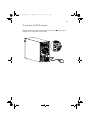
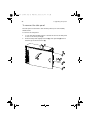
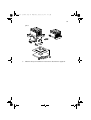
The Acer Altos G510 series server is a
powerful dual-processor system loaded with
a host of new and innovative features. The
system offers a new standard for flexible
productivity ideal for general business
applications, email, web service, file
clustering and print services.
BB!H621!.!FO/cppl!!Qbhf!4!!Xfeoftebz-!Kbovbsz!9-!3114!!21;63!BN
3
Features summary
Highlighted below are the system’s key features:
•
Single or dual Intel® XeonTM processor
•
ServerWorks GC-SL core logic chipset consisting of three distinct
components:
•
CMIC SL - north/host bridge
•
CSB5 - south bridge
•
CIOB-X2 - I/O bridge
•
Onboard Broadcom BCM5702 10/100/1000Base-T Gigabit Ethernet
controller
•
LSI® 53C 1020 single Channel SCSI controller chipset
•
SCSI Channel - one 68-pin Ultra320/m SCSI connector
•
Six PCI bus slots with three separate bus segments
•
Two 64-bit/100 MHz PCI-X bus slots
•
Two 64-bit/66 MHz PCI bus slot
•
Two 32-bit/33 MHz PCI bus slot
•
ATI Rage XL chipset with 8 MB SDRAM of video memory
•
Four DIMM sockets supporting ECC 266 MHz DDR modules for a
maximum memory capacity of 4 GB
•
Media storage
• 3.5-inch, 1.44 MB floppy drive
• IDE CD-ROM drive
•
Additional media storage capacity
• Altos G510 - one Hot Plug HDD cages (6 hard disk capacity)
• Altos G510 Basic - one SCSI cable cage
•
External ports
• PS/2-compatible keyboard and
mouse port
• Two USB ports
• VGA/monitor port
•
•
Serial port
•
•
Parallel/printer port
One LAN port
Power supply unit (PSU)
• Altos G510 - 450-watts redundant power supply (with power
distribution board)
• Altos G510 Basic - 450-watts standard power supply
BB!H621!.!FO/cppl!!Qbhf!5!!Xfeoftebz-!Kbovbsz!9-!3114!!21;63!BN
4
1 System tour
External and internal structure
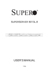
Front bezel
Note: One pair of system keys are provided (attached to the rear
panel of the system).
Note: Unless otherwise indicated, all front bezel features
indicated on the table below apply to both the Altos G510 and
Altos G510 Basic models.
No.
Description
1
Power indicator
2
Hard disk activity indicator
BB!H621!.!FO/cppl!!Qbhf!6!!Xfeoftebz-!Kbovbsz!9-!3114!!21;63!BN
5
No.
Description
3
System fault indicator
4
Hard disk fault indicator (for Altos G510 model only)
5
Security keylock
6
Front bezel
BB!H621!.!FO/cppl!!Qbhf!7!!Xfeoftebz-!Kbovbsz!9-!3114!!21;63!BN
6
1 System tour
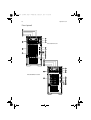
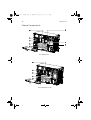
Front panel
Altos G510 model
Altos G510 Basic model
BB!H621!.!FO/cppl!!Qbhf!8!!Xfeoftebz-!Kbovbsz!9-!3114!!21;63!BN
7
Note: Unless otherwise indicated, all front panel features
indicated on the table below apply to both the Altos G510 and
Altos G510 Basic models.
No.
Description
1
CD-ROM drive Stop/Eject button
2
CD-ROM drive activity indicator
3
CD-ROM drive
4
Volume control
5
CD-ROM drive Headphone/Earphone port
6
5.25-inch half-height bay
7
Altos G510 - Hot Plug HDD cage
Altos G510 Basic - non-Hot Plug HDD cable cage
8
HDD carrier (for Hot Plug HDD Cage only)
9
Floppy drive Eject button
10
Floppy drive
11
Floppy drive activity indicator
12
Power button
13
Reset button
14
Power indicator
15
Hard disk activity indicator
16
System fault indicator
17
Hard disk fault indicator (for Altos G510 model only)
BB!H621!.!FO/cppl!!Qbhf!9!!Xfeoftebz-!Kbovbsz!9-!3114!!21;63!BN
8
1 System tour
No.
Description
18
Hot Plug HDD power indicator 1 (for Hot Plug HDD cage only)
19
Hot Plug HDD access indicator 2 (for Hot Plug HDD cage only)
1 This indicator lights up green to indicate HDD power on and lights up in red when a
HDD fault occurs.
2 This indicator lights up green to indicate drive access.
Note: During Rebuild, lights flash alternately red and green.
Note: Feature 17 only operates when the Hot Plug HDD cage is
installed and RAID configured.
BB!H621!.!FO/cppl!!Qbhf!:!!Xfeoftebz-!Kbovbsz!9-!3114!!21;63!BN
9
Rear panel
Altos G510 model
Altos G510 Basic model
BB!H621!.!FO/cppl!!Qbhf!21!!Xfeoftebz-!Kbovbsz!9-!3114!!21;63!BN
10
1 System tour
Note: Unless otherwise indicated, all rear panel features
indicated on the table below apply to both the Altos G510 and
Altos G510 Basic models.
No.
Icon
Description
1
Altos G510 model - Main power supply unit
Altos G510 Basic model - Standard 450-watts PSU
2
PS/2 keyboard port
3
PS/2 mouse port
4
USB ports
5
RDM LAN port (10 Mbps) 1
This port is not accessible on Altos G510 and G510
Basic models.
6
Serial port
7
Parallel/printer port
8
VGA/monitor port
9
Gigabit LAN port (10/100/1000 Mbps)
10
Expansion slots
11
Main power supply indicator 2
(for Altos G510 model only)
12
Main power supply fail indicator 3
(for Altos G510 model only)
13
Main power supply AC power indicator 4
(for Altos G510 model only)
14
Main power supply cable socket
BB!H621!.!FO/cppl!!Qbhf!22!!Xfeoftebz-!Kbovbsz!9-!3114!!21;63!BN
11
No.
Icon
Description
15
Rear system fan
16
Ventilation slots
N kL^=çå=^äíçë=dRNM=çê=dRNM=_~ëáÅ=ãçÇÉäK=oÉëÉêîÉÇ=Ñçê=ÑìíìêÉ=ãçÇÉäëK
O qÜáë=áåÇáÅ~íçê=ïáää=äáÖÜí=ìé=ÖêÉÉå=ïÜÉå=íÜÉ=éçïÉê=ëìééäó=ãçÇìäÉ=áë=ÑìåÅíáçåáåÖ=éêçéÉêäóK
P qÜáë=áåÇáÅ~íçê=ïáää=äáÖÜí=ìé=~ãÄÉê=ïÜÉå=íÜÉ=éçïÉê=ëìééäó=ãçÇìäÉ=çê=~åó=mpr=áåíÉêå~ä=Ñ~å
Ñ~áäëK
Q qÜáë=áåÇáÅ~íçê=ïáää=äáÖÜí=ìé=ÖêÉÉå=ïÜÉå=íÜÉ=áåéìí=îçäí~ÖÉ=áë=ïáíÜáå=íÜÉ=^`=áåéìí=îçäí~ÖÉ
ê~åÖÉK=
BB!H621!.!FO/cppl!!Qbhf!23!!Xfeoftebz-!Kbovbsz!9-!3114!!21;63!BN
12
1 System tour
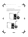
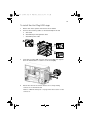
Internal components
Altos G510 model
Altos G510 Basic model
BB!H621!.!FO/cppl!!Qbhf!24!!Xfeoftebz-!Kbovbsz!9-!3114!!21;63!BN
13
Note: Unless otherwise indicated, all internal components
indicated on the table below apply to both the Altos G510 and
Altos G510 Basic models.
No.
Description
1
Altos G510 model - Power supply module bay for redundant
PSU 1
Altos G510 Basic model - Standard 450-watts PSU
2
Rear system fan
3
Rear system fan release latch
4
PCI bus slot
5
Mainboard
6
Air baffle
7
Power distribution board (for Altos G510 model only)
8
Hot-swap HDD SAF-TE board (for Altos G510 model only)
9
Hot-swap HDD backplane board (for Altos G510 model only)
N qÜçìÖÜ=íÜÉ=ëóëíÉã=ëìééçêíë=íïç=ÜçíJëï~éé~ÄäÉ=éçïÉê=ëìééäó=ãçÇìäÉ=Ä~óëI=íÜÉ
ëóëíÉã=ÅçãÉë=ÄìåÇäÉÇ=ïáíÜ=~=ëáåÖäÉ=éçïÉê=ëìééäó=ãçÇìäÉ=çåäóK==vçì=Ü~îÉ=íÜÉ
çéíáçå=íç=éìêÅÜ~ëÉ=~å=Éñíê~=éçïÉê=ëìééäó=ãçÇìäÉ=íç=éêçîáÇÉ=íÜÉ=ëóëíÉã=ïáíÜ==êÉJ
ÇìåÇ~åí=éçïÉê=ëçìêÅÉK
BB!H621!.!FO/cppl!!Qbhf!25!!Xfeoftebz-!Kbovbsz!9-!3114!!21;63!BN
14
1 System tour
System boards
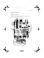
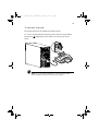
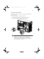
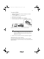
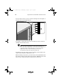
Mainboard layout
The mainboard becomes accessible once you open the system. It
should look like the figure shown below
BB!H621!.!FO/cppl!!Qbhf!26!!Xfeoftebz-!Kbovbsz!9-!3114!!21;63!BN
15
Note: Unless otherwise indicated, all mainboard features
indicated on the table below apply to both the Altos G510 and
Altos G510 Basic models.
Item
Description
BT1
Battery
BZ1
Buzzer
CN1
+12V power connector
CN2
ATX power connector
CN3
USB ports
CN4
VGA/monitor port
COM1
Serial port
CPU1 and CPU2
CPU sockets
DM1 - DM4
DIMM slots
J2
Front panel connector
J3
Floppy disk drive connector
J4
Primary IDE connector
J5
Secondary IDE connector
J7
Chassis intrusion connector
J9
BMC daughter board connector
J10
MLB Jumper
1-2 Password Enable (Default Setting: Off)
3-4 Clear NVRAM (Default Setting: Off)
5-6 Recovery Mode (Default Setting: Off)
J13
Wake on LAN connector
J14
SCSI RAID card HDD LED connector
BB!H621!.!FO/cppl!!Qbhf!27!!Xfeoftebz-!Kbovbsz!9-!3114!!21;63!BN
16
1 System tour
Item
Description
JF1
CPU 1 fan connector
JF4
Front fan connector
JF5
CPU 2 fan connector
JF8
Rear system fan connector
JP2
Power supply mangement cable connector
(connected to PDB board)
JP8
IPMB connector
JP9
SCSI HDD management cable connector
(conneted to Hot Plug HDD cage backplane board)
JP10
Connector for Remote Management Card (RMC)
J15
Power On/Off connector for RMC
J16
Reset Connector for RMC
KM1
Upper: PS/2 mouse port
Lower: PS/2 keyboard port
LAN1
Gigabit LAN port (10/100/1000 Mbps)
LTP1
Parallel/printer port
SLOT1
64-bit/66 MHz PCI bus slot (Zero Channel RAID compliant) (Green)
SLOT2
64-bit/66 MHz PCI bus slot (White)
SLOT3 and SLOT4
64-bit/100 MHz PCI-X bus slots (Blue)
SLOT5 and SLOT6
32-bit/33 MHz PCI bus slot (5V Support) (White)
SCSI1
SCSI connector
U4
ServerWorks CMIC-SL chipset (north bridge)
U12
System clock
U18
BCM5702 Gigabit LAN chipset
BB!H621!.!FO/cppl!!Qbhf!28!!Xfeoftebz-!Kbovbsz!9-!3114!!21;63!BN
17
Item
Description
U19
LSI 53C1020 SCSI Chipset
U27
ServerWorks CIOBx2 chipsets (I/O bridge)
U34
ATI Rage XL VGA chipset
U45
ServerWorks CSB5 chipset (south bridge)
U46
Flash BIOS
U48
PC87414 SIO - Super I/O chipset
U49
Video RAM
USB1
USB connector
VRM9.1
Onboard VRMs (Voltage Regulator Module)
BB!H621!.!FO/cppl!!Qbhf!29!!Xfeoftebz-!Kbovbsz!9-!3114!!21;63!BN
18
1 System tour
Hot Plug HDD Cage backplane board layout
Note: The Hot Plug HDD cage board feature is only applicable to
the Altos G510 model.
Label
Description
1
122-pin SAF-TE connector
2
80-pin SCSI HDD connector
3
68-pin SCSI HDD connector
4
SCSI HDD management cable connector (I2C
bus)
5
Power connector
BB!H621!.!FO/cppl!!Qbhf!2:!!Xfeoftebz-!Kbovbsz!9-!3114!!21;63!BN
2 System setup
BB!H621!.!FO/cppl!!Qbhf!31!!Xfeoftebz-!Kbovbsz!9-!3114!!21;63!BN
20
2 System setup
This chapter gives you instructions on how to set up
the system. Procedures on how to connect
peripherals are also explained.
BB!H621!.!FO/cppl!!Qbhf!32!!Xfeoftebz-!Kbovbsz!9-!3114!!21;63!BN
21
Setting up the system
Preinstallation requirements
Selecting a site
Before unpacking and installing the system, select a suitable site for
the system for maximum efficiency. Consider the following factors
when choosing a site for the system:
•
Near a grounded power outlet
•
Clean and dust-free
•
Stable surface free from vibration
•
Well-ventilated and away from sources of heat
•
Secluded from electromagnetic fields produced by electrical
devices such as air conditioners, radio and TV transmitters, etc.
Checking the package contents
Check the following items from the package:
•
Acer Altos G510 series system
•
Acer Altos G510 series User’s guide
•
Acer EasyBUILDTM
•
Acer Altos G510 series Accessory box
•
System keys (attached to the rear panel of the system)
If any of the above items are damaged or missing, contact your dealer
immediately.
Save the boxes and packing materials for future use.
BB!H621!.!FO/cppl!!Qbhf!33!!Xfeoftebz-!Kbovbsz!9-!3114!!21;63!BN
22
2 System setup
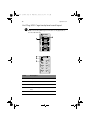
Connecting peripherals
The system unit, keyboard, mouse, and monitor constitute the basic
system. Before connecting any other peripherals, connect these basic
peripherals first to test if the system is running properly. Instructions
on how to connect a printer is also described here, refer to page 25.
Note: Unless otherwise indicated, all illustrations shown in this
section show the Altos G510 server chassis.
To connect the PS/2 keyboard
Plug the keyboard cable into the PS/2 keyboard port
port) located on the rear panel of the server.
(purple
BB!H621!.!FO/cppl!!Qbhf!34!!Xfeoftebz-!Kbovbsz!9-!3114!!21;63!BN
23
To connect the PS/2 mouse
Plug the PS/2 mouse cable into the PS/2 mouse port
located on the rear panel of the server.
(green port)
BB!H621!.!FO/cppl!!Qbhf!35!!Xfeoftebz-!Kbovbsz!9-!3114!!21;63!BN
24
2 System setup
To connect the VGA monitor
To connect the VGA monitor, simply plug the monitor cable into the
VGA/monitor port
server.
(blue port) located on the rear panel of the
BB!H621!.!FO/cppl!!Qbhf!36!!Xfeoftebz-!Kbovbsz!9-!3114!!21;63!BN
25
To connect a printer
The system supports both parallel and serial printers.
To connect a parallel printer, plug the printer cable into the parallel/
printer port
server.
(burgundy port) located on the rear panel of the
Note: If you are using a USB printer, connect the printer cable
into the USB port located on the server’s rear panel.
BB!H621!.!FO/cppl!!Qbhf!37!!Xfeoftebz-!Kbovbsz!9-!3114!!21;63!BN
26
2 System setup
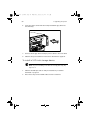
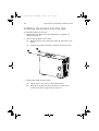
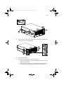
To connect the power cable
Plug the power cable into the power cable socket located on the rear
panel of the server. Then plug the other end of the power cable into a
power outlet. The figure below shows a complete connection of the
whole system.
Altos G510 model
Altos G510 Basic model
BB!H621!.!FO/cppl!!Qbhf!38!!Xfeoftebz-!Kbovbsz!9-!3114!!21;63!BN
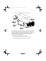
27
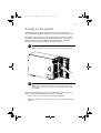
Turning on the system
After making sure that you have properly set up the system and
connected all the required cables, you can now power on the system.
To power on the system, press the power button on the front panel.
The system starts up and displays a welcome message. After that, a
series of power-on self-test (POST) messages appears. The POST
messages indicate if the system is running well or not.
Note: The illustration below shows the Altos G510 server chassis.
Note: If the system does not turn on or boot after pressing the
power button, go to the next section for the possible causes of the
boot failure.
Aside from the POST messages, you can determine if the system is in
good condition by checking if the following occurred:
•
Power indicator on the front panel lights up (green)
•
Num Lock, Caps Lock, and Scroll Lock indicators on the keyboard
light up
BB!H621!.!FO/cppl!!Qbhf!39!!Xfeoftebz-!Kbovbsz!9-!3114!!21;63!BN
28
2 System setup
Power-on problems
If the system does not boot after you have applied power, check the
following factors that might have caused the boot failure.
•
The external power cable may be loosely connected.
Check the power cable connection from the power source to the
power cable socket on the rear panel. Make sure that the cable is
properly connected to the power source and to the power cable
socket.
•
No power comes from the grounded power outlet.
Have an electrician check your power outlet.
•
Loose or improperly connected internal power cables.
Check the internal cable connections. If you are not confident to
perform this step, ask a qualified technician to assist you.
Warning! Make sure all power cords are disconnected from
the electrical outlet before performing this task.
Note: If you have gone through the preceding actions and the
system still fails to boot, ask your dealer or a qualified technician
for assistance.
BB!H621!.!FO/cppl!!Qbhf!3:!!Xfeoftebz-!Kbovbsz!9-!3114!!21;63!BN
29
Operating system configuration
The Acer Altos G510 series server comes with Acer EasyBUILDTM that
allows you to conveniently install your choice of operating system. To
start using EasyBUILD, follow the steps below.
1
Locate the EasyBUILD System CD included in the system package.
2
With your system turn on, gently press the CD-ROM drive Stop/
Eject button.
3
When the disc tray slides open, insert the EasyBUILD System CD
with the label or title side of the disc facing upward.
Note: When handling the disc, hold it by the edges to avoid
smudges or fingerprints.
4
Gently press the disc down to make sure that it is properly
inserted.
Caution! While pressing the disc, be careful not to bend the disc
tray. Make sure that the disc is properly inserted before closing
the disc tray. Improper insertion may damage both the disc and
the CD-ROM drive.
5
Gently press the drive Stop/Eject button again to close the disc
tray.
6
The Acer EasyBUILD sequence begins. Follow all onscreen
instructions.
For more information, refer to the EasyBUILDTM Installation guide.
BB!H621!.!FO/cppl!!Qbhf!41!!Xfeoftebz-!Kbovbsz!9-!3114!!21;63!BN
30
2 System setup
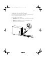
Network connection
The server has one 10/100/1000 Mbps Gigabit Etherned LAN port
located on the rear panel for fast network connection.
To connect to the network, simply plug the network cable into the
Gigabit LAN port
(gray port).
Note: The illustration below shows the Altos G510 server chassis.
Note: Consult the operating system manual for information on
how to configure the network setup.
BB!H621!.!FO/cppl!!Qbhf!42!!Xfeoftebz-!Kbovbsz!9-!3114!!21;63!BN
31
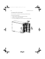
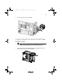
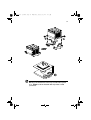
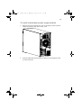
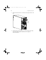
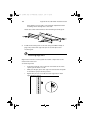
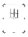
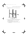
Tower-to-rack option
Aside from its tower configuration, the Acer Altos G510 series server
can also be mounted in a rack-model position. A rack mount kit is
available for customers who want to convert a tower-mounted system
to rack-model design. To purchase a rack mount kit, contact your local
Acer representative.
The figure below shows the server in a rack-mount position.
Note: The illustration below shows the Altos G510 server chassis.
Rack Mount instructions are provided as an appendix to this
manual.
BB!H621!.!FO/cppl!!Qbhf!43!!Xfeoftebz-!Kbovbsz!9-!3114!!21;63!BN
32
2 System setup
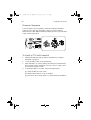
Turning off the system
To turn off the server, on the Windows taskbar click on the Start
button, point to Shut Down..., select Shut down from the
drop-down window then click on OK. You can then turn off all
peripherals connected to your server.
If you are unable to shutdown the server within Windows, press and
hold the power button for at least four seconds to force quit all
applications and shut down.
BB!H621!.!FO/cppl!!Qbhf!44!!Xfeoftebz-!Kbovbsz!9-!3114!!21;63!BN
33
BB!H621!.!FO/cppl!!Qbhf!45!!Xfeoftebz-!Kbovbsz!9-!3114!!21;63!BN
34
2 System setup
BB!H621!.!FO/cppl!!Qbhf!46!!Xfeoftebz-!Kbovbsz!9-!3114!!21;63!BN
3 Upgrading
the system
BB!H621!.!FO/cppl!!Qbhf!47!!Xfeoftebz-!Kbovbsz!9-!3114!!21;63!BN
36
3 Upgrading the system
This chapter discusses the precautionary
measures and installation procedures you
need to know when upgrading the system.
BB!H621!.!FO/cppl!!Qbhf!48!!Xfeoftebz-!Kbovbsz!9-!3114!!21;63!BN
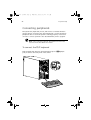
Upgrading the system
Certain components of the server are upgradeable such as the drives,
the CPU, the memory, and the expansion cards. However, for safety
purposes, we do not recommend that you perform these upgrades
yourself. If you want to replace or upgrade any of these components,
contact your dealer or a qualified service technician for assistance.
Important: Observe the installation precautions described in the
subsequent section when installing or removing a server
component.
Installation precautions
Before you install any server component, we recommend that you read
the following sections. These sections contain important ESD
precautions along with preinstallation and post-installation
instructions.
ESD precautions
Electrostatic discharge (ESD) can damage the processors, motherboard,
disk drives, expansion boards, or other components. Always observe
the following precautions before you install a server component:
1
Do not remove a component from its protective packaging until
you are ready to install it.
2
Wear a wrist grounding strap and attach it to a metal part of the
server before handling components. If a wrist strap is not
available, maintain contact with the server throughout any
procedure requiring ESD protection.
Preinstallation instructions
Always observe the following before you install any component:
1
Turn off the system and all the peripherals connected to it.
2
Unplug all cables from the power outlets.
BB!H621!.!FO/cppl!!Qbhf!49!!Xfeoftebz-!Kbovbsz!9-!3114!!21;63!BN
38
3 Upgrading the system
3
Open the system according to the instructions on page 39.
4
Follow the ESD precautions described in this section when
handling a server component.
5
Remove any expansion board(s) or peripheral(s) that block access
to the DIMM socket or other component connector.
See the following sections for specific installation instructions on the
component you want to install.
Warning! Failure to properly turn off the server before you
start installing components may cause serious damage. Do
not attempt the procedures described in the following
sections unless you are a qualified service technician.
Post-installation instructions
Observe the following after installing a server component:
1
See to it that all components are installed according to the
described step-by-step instructions.
2
Reinstall any expansion board(s) or peripheral(s) that you have
previously removed.
3
Reinstall the air baffle.
4
Reinstall the chassis panels.
5
Connect the necessary cables.
6
Turn on the system.
BB!H621!.!FO/cppl!!Qbhf!4:!!Xfeoftebz-!Kbovbsz!9-!3114!!21;63!BN
39
Opening the server
Caution! Before you proceed, make sure that you have turned
off your system and all peripherals connected to it. Read the
“Preinstallation instructions” on page 37.
You need to open the server before you can install additional
components. The front bezel and left side panel are removable to
allow access to the system’s internal components. Refer to the
following sections for instructions.
Before opening the server
Before opening the server, observe the following precautions:
1
Turn off the system and all the peripherals connected to it.
2
Unplug all cables from the power outlets.
3
Place the system unit on a flat, stable surface.
Note: The illustrations used in this section show the Altos G510
server chassis.
To open the front bezel
A security lock secures the front bezel to protect your system unit
against unauthorized access.
To open the front bezel:
1
Insert the key into the lock and turn it clockwise until it points to
the unlocked icon .
2
Open the front bezel.
BB!H621!.!FO/cppl!!Qbhf!51!!Xfeoftebz-!Kbovbsz!9-!3114!!21;63!BN
40
3 Upgrading the system
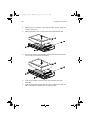
To remove the front bezel
The front bezel is attached to the chassis by screwless hinges.
To remove the front bezel:
1
Unlock the door with the key (when necessary).
2
Open it to more than a 45° angle.
3
Lift it up a little (1), then move it away from the chassis (2).
BB!H621!.!FO/cppl!!Qbhf!52!!Xfeoftebz-!Kbovbsz!9-!3114!!21;63!BN
41
To remove the inner (front) panel
The inner front panel is attached to the chassis by thumb latches at
the top and screwless hinges at the bottom.
To remove the inner front panel:
1
Simultaneously slide the two thumb catches at the top to release
the latches.
2
Open the panel 90 degrees, until it is perpendicular to the
chassis.
3
Gently pull it away from the chassis.
BB!H621!.!FO/cppl!!Qbhf!53!!Xfeoftebz-!Kbovbsz!9-!3114!!21;63!BN
42
3 Upgrading the system
To remove the side panel
The side panel is attached to the server by three (non-removeable)
thumbscrews.
To remove the side panel:
1
Loosen the three thumbscrews located at the end of the left panel
closest to the front panel (1).
2
Slide the left panel slightly forward (2), then upward (3) before
detaching it from the chassis (4).
BB!H621!.!FO/cppl!!Qbhf!54!!Xfeoftebz-!Kbovbsz!9-!3114!!21;63!BN
43
To remove the air baffle
Remove the air baffle to allow easy access to the motherboard and
system components.
Follow the steps below to remove the air baffle:
1
Press the release latches on both ends of the air baffle.
2
Pull out the air baffle to remove it from the chassis.
Caution! After completing the component upgrade/replacement
procedures, do not forget to reinstall the air baffle before
replacing the chassis panels. Failure to do so will reduce the
system’s cooling efficiency which can adversely affect performance
or cause damage due to overheating.
BB!H621!.!FO/cppl!!Qbhf!55!!Xfeoftebz-!Kbovbsz!9-!3114!!21;63!BN
44
3 Upgrading the system
Configuring the Hot Plug HDD cage
This section includes instructions for removing and installing the
Hot Plug HDD cage as well as procedures on how to install a hard disk
into the cage’s hard disk carrier.
Note: The Hot Plug HDD cage feature is only applicable to the
Altos G510 model.
To remove the Hot Plug HDD cage
Important: Before detaching the Hot Plug HDD cage from the
chassis, make sure to first remove all hard disks from their carriers.
For instructions, refer to the succeeding section.
1
Remove the front bezel, inner front panel, side panel and air
baffle. Refer to the previous section for detailed intructions.
2
Disconnect the following cables from the cage:
3
a
SCSI cable
b
SCSI HDD 6 pin management cable
c
SCSI HDD power cable
Loosen the four thumbscrews that secure the cage to the chassis
(1).
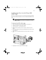
BB!H621!.!FO/cppl!!Qbhf!56!!Xfeoftebz-!Kbovbsz!9-!3114!!21;63!BN
45
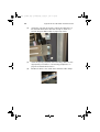
4
Pull the cage from the chassis (2).
To install a hard disk into the Hot Plug HDD cage
hard disk carrier
Note: You need not remove the Hot Plut HDD cage from the
chassis to install a hard disk into the cage’s hard disk carrier.
1
Press your finger to the SCSI HDD release lever (1), then pull out
the hard disk carrier from the cage (2).
BB!H621!.!FO/cppl!!Qbhf!57!!Xfeoftebz-!Kbovbsz!9-!3114!!21;63!BN
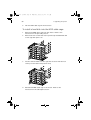
46
3 Upgrading the system
2
Remove the four screws to open the hard disk carrier. Keep the
screws for later use.
3
When applicable, pull out any previously installed hard disk.
4
Install a hard disk in the hard disk carrier then secure it with the
four screws you have removed earlier.
5
Insert the hard disk carrier into the cage with the lever still
extended.
6
Push the lever back until it clicks into place. Make sure that the
drive is properly inserted before closing the lever.
BB!H621!.!FO/cppl!!Qbhf!58!!Xfeoftebz-!Kbovbsz!9-!3114!!21;63!BN
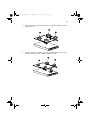
47
To install the Hot Plug HDD cage
1
Detach the chassis panels and remove the air baffle.
2
Connect the following cables to the SCSI backplane board:
a
SCSI cable
b
SCSI HDD 6 pin management cable
c
SCSI HDD power cable
3
Insert the Hot Plug HDD cage into the housing (1), then tighten
the four thumbscrews to secure it to the chassis (2).
4
Attach the other end of these cables to the corresponding
connectors on the mainboard.
Refer to “Mainboard layout” on page 14 for the location of the
connectors.
BB!H621!.!FO/cppl!!Qbhf!59!!Xfeoftebz-!Kbovbsz!9-!3114!!21;63!BN
48
5
3 Upgrading the system
Reinstall the air baffle and the chassis panels.
BB!H621!.!FO/cppl!!Qbhf!5:!!Xfeoftebz-!Kbovbsz!9-!3114!!21;63!BN
49
Configuring the non-Hot Plug HDD
cable cage
This section includes instructions for removing and installing the HDD
cable cage as well as procedures on how to install a hard disk into the
cage.
Note: The HDD cable cage feature is only applicable to the Altos
G510 Basic model.
To remove the HDD cable cage
1
Turn off the system and all the peripherals connected to it.
2
Unplug all cables from the power outlets.
3
Place the system on a flat, stable surface.
4
Remove the front bezel, inner front panel, side panel, and air
baffle.
5
Disconnect the SCSI cable and the SCSI HDD power cable from the
hard disk drive.
6
Loosen the four thumbscrews that secure the cage to the chassis
(1).
7
Slightly pull out the cage from the chassis (2).
BB!H621!.!FO/cppl!!Qbhf!61!!Xfeoftebz-!Kbovbsz!9-!3114!!21;63!BN
50
8
3 Upgrading the system
Pull the HDD cable cage from the chassis.
To install a hard disk into the HDD cable cage
1
Remove the HDD cable cage from the chassis. Refer to the
instructions in the preceding section.
2
Remove the four screws that secure a previously installed hard disk
to the cage then pull it out.
3
Install a new hard disk into the cage then secure it with the four
screws you removed in the previous step.
4
Reinstall the HDD cable cage to the chassis. Refer to the
instructions in the subsequent section.
BB!H621!.!FO/cppl!!Qbhf!62!!Xfeoftebz-!Kbovbsz!9-!3114!!21;63!BN
51
To install the SCSI cable cage
1
Turn off the system and all the peripherals connected to it.
2
Unplug all cables from the power outlets.
3
Place the system unit on a flat, stable surface.
4
Remove the front bezel, inner front panel, side panel, and air
baffle.
5
Insert the HDD cable cage into the housing (1), then tighten the
four thumbscrews to secure it to the chassis (2).
6
Connect the SCSI cable and the SCSI HDD power cable to the hard
disk drive.
7
Reinstall the air baffle and the chassis panels.
BB!H621!.!FO/cppl!!Qbhf!63!!Xfeoftebz-!Kbovbsz!9-!3114!!21;63!BN
52
3 Upgrading the system
Installing and removing storage
devices
The system supports one 3.5-inch and two 5.25-inch internal storage
devices. The system comes pre-installed with a floppy drive and a CDROM drive. The empty 5.25-inch half-height bay allows you to install
additional drives such as another CD-ROM drive or a tape drive.
To replace the 3.5-inch floppy drive
1
Observe the ESD precautions and pre-installation procedures
described on page 37.
2
Disconnect the IDE and floppy drive cables from the old drive.
3
Press the release bracket on both sides of the drive carrier (1)
before pulling it out from the chassis (2).
BB!H621!.!FO/cppl!!Qbhf!64!!Xfeoftebz-!Kbovbsz!9-!3114!!21;63!BN
53
4
Remove the four screws that hold the old drive to the drive carrier
then pull it out.
5
Install a new 3.5-inch drive in the drive carrier then secure it with
the four screws you removed in the previous step.
BB!H621!.!FO/cppl!!Qbhf!65!!Xfeoftebz-!Kbovbsz!9-!3114!!21;63!BN
54
3 Upgrading the system
6
Insert the drive carrier with the newly-installed floppy drive into
the drive bay.
7
Connect the floppy drive and 4-pin power cables to the new drive.
8
Observe the post-installation instructions described on page 38.
To install a 5.25-inch storage device
Note: If you are installing a new drive in an empty drive bay, skip
steps 2 to 4.
1
Observe the ESD precautions and pre-installation procedures
described on page 37.
2
Disconnect the power and IDE cables from the old drive.
BB!H621!.!FO/cppl!!Qbhf!66!!Xfeoftebz-!Kbovbsz!9-!3114!!21;63!BN
55
3
Loosen and remove the two screws from each side of the CD-ROM
drive (1) before pulling it from the chassis (2).
4
Insert the CD-ROM drive into the drive bay and secure it with the
screws you removed in the previous step.
5
Connect the power and IDE cables to the new drive.
6
Observe the post-installation instructions described on page 38.
BB!H621!.!FO/cppl!!Qbhf!67!!Xfeoftebz-!Kbovbsz!9-!3114!!21;63!BN
56
3 Upgrading the system
Upgrading the CPU
This section includes instructions for removing and installing a CPU.
To remove a CPU with heatsink
Before installing a new CPU in a socket, remove first any previously
installed CPU from that socket.
Important: Before removing a CPU from the mainboard, make
sure to create a backup file of all important data.
1
Observe the ESD precautions and pre-installation procedures
described on page 37.
2
Locate the CPU socket on the mainboard.
3
To detach the CPU from its socket, follow the steps below:
(1) Depress then lift up each of the locking levers to a 90° angle.
(2) Remove the heatsink.
(3) Lift the CPU locking lever until it is fully extended.
(4) Gently unseat and pull the CPU from the socket.
BB!H621!.!FO/cppl!!Qbhf!68!!Xfeoftebz-!Kbovbsz!9-!3114!!21;63!BN
57
Warning! The heatsink becomes very hot when the system
is on. NEVER touch the heatsink with any metal or with
your hands.
BB!H621!.!FO/cppl!!Qbhf!69!!Xfeoftebz-!Kbovbsz!9-!3114!!21;63!BN
58
3 Upgrading the system
Processor Sequence
If only one CPU is to be installed, it must be installed in the CPU 1
socket; if such is the case, the CPU 2 socket no longer requires a
termination module. When installing multiple processors, install them
in the order shown below.
To install a CPU with heatsink
1
Observe the ESD precautions and pre-installation procedures
described on page 37.
2
Locate the CPU socket on the mainboard.
3
Align the CPU to its socket, making sure that pin 1 (indicated by
the notched corner) of the CPU connects to hole 1 of the socket
(on the bottom right corner).
4
To install the CPU to its socket, follow the steps below:
(1) Insert the CPU into the socket.
(2) Replace the heatsink on top of the CPU.
(2) Press down the locking levers to lock the heatsink and CPU in
BB!H621!.!FO/cppl!!Qbhf!6:!!Xfeoftebz-!Kbovbsz!9-!3114!!21;63!BN
59
place.
5
Observe the post-installation instructions described on page 38.
BB!H621!.!FO/cppl!!Qbhf!71!!Xfeoftebz-!Kbovbsz!9-!3114!!21;63!BN
60
3 Upgrading the system
Upgrading the system memory
This section includes instructions for removing and installing a
memory module.
To remove a DIMM
Before installing a new DIMM in a socket, remove first any previously
installed DIMM from that socket.
Important: Before removing any DIMM from the mainboard,
make sure to create a backup file of all important data.
1
Observe the ESD precautions and pre-installation procedures
described on page 37.
2
Locate the DIMM socket on the mainboard.
3
Press the holding clips on both sides of the socket outward to
release the DIMM (1).
4
Gently pull the DIMM upward to remove it from the socket (2).
Note: Place your forefingers on the top of the DIMM before
pressing the holding clips to gently disengage the DIMM from the
socket.
BB!H621!.!FO/cppl!!Qbhf!72!!Xfeoftebz-!Kbovbsz!9-!3114!!21;63!BN
61
To install a DIMM
1
Observe the ESD precautions and pre-installation procedures
described on page 37.
2
Locate the DIMM socket on the mainboard.
3
Open the clips on the socket.
4
Align then insert the DIMM into the socket (1).
5
Press the holding clips inward to lock the DIMM in place (2).
DIMM must be installted in the following order: DM1. DM2, DM3 and DM4
Note: The DIMM socket is slotted to ensure proper installation.
If you insert a DIMM but it does not fit easily into the socket, you
may have inserted it incorrectly. Reverse the orientation of the
DIMM and insert it again.
6
Observe the post-installation instructions described on page 38.
Reconfiguring the system memory
The system automatically detects the amount of memory installed.
Run the BIOS setup to view the new value for total system memory and
make a note of it.
BB!H621!.!FO/cppl!!Qbhf!73!!Xfeoftebz-!Kbovbsz!9-!3114!!21;63!BN
62
3 Upgrading the system
Installing an expansion card
This section explains how to install an expansion card. The onboard
expansion slots support PCI (Peripheral Component Interconnect)
cards.
Note: The BIOS setup automatically detects and assigns resources
to the new device (applicable only to Plug-and-Play expansion
cards).
To install an expansion card
Note: The illustrations used in this section show the Altos G510
server chassis.
1
Observe the ESD precautions and pre-installation procedures
described on page 37.
2
Locate an empty expansion slot on the mainboard.
3
Loosen the bracket screw on the rear panel.(1).
4
Pull out the card bracket (2).
5
Remove the expansion card from its protective packaging.
BB!H621!.!FO/cppl!!Qbhf!74!!Xfeoftebz-!Kbovbsz!9-!3114!!21;63!BN
63
6
Align the card in the empty slot on the mainboard. Make sure that
the card is properly seated.
7
Insert the bracket with the card into the selected slot (1).
8
Secure the card with the bracket screw removed in step 3 above
(2).
9
Observe the post-installation instructions described on page 38.
BB!H621!.!FO/cppl!!Qbhf!75!!Xfeoftebz-!Kbovbsz!9-!3114!!21;63!BN
64
3 Upgrading the system
Installing a redundant power supply
module
The Altos G510 server power subsystem consists of two hot-swappable
power supply module bays that accept standard 450-watts power
supply modules. The system comes bundled with only a single power
supply module leaving one power supply module bay empty. You have
the option to purchase an extra power supply module to provide your
system with redundant power source. This power configuration
enables a fully-configured system to continue running even if one
power supply module fails.
Note: The redundant power source feature is only applicable to
the Altos G510 model.
WARNING! To reduce the risk of personal injury or
damage to the equipment, the installation of power
supply modules should be referred to individuals who are
qualified to service server systems and are trained to deal
with equipment capable of generating hazardous energy
levels.
WARNING! To reduce the risk of personal injury from
hot surfaces, observe the thermal labels on each power
supply module. You can also consider wearing protective
gloves.
WARNING! To reduce the risk of personal injury from
electric shock hazards, do not open the power supply
modules. There are no serviceable parts inside the
module.
Caution! Electrostatic discharge can damage electronic
components. Make sure that you are properly grounded
before handling a power supply module.
BB!H621!.!FO/cppl!!Qbhf!76!!Xfeoftebz-!Kbovbsz!9-!3114!!21;63!BN
65
To install a redundant power supply module
1
Remove the screw securing the cover of the empty optional power
supply module bay, then remove the cover.
2
Slide the redundant power supply module into the empty bay until
you feel resistance.
BB!H621!.!FO/cppl!!Qbhf!77!!Xfeoftebz-!Kbovbsz!9-!3114!!21;63!BN
66
3 Upgrading the system
3
Press the module handle to secure the power supply module to the
bay.
4
Verify that the power indicators on both the main power supply
and on the newly installed redundant power supply are
illuminated (green).
BB!H621!.!FO/cppl!!Qbhf!78!!Xfeoftebz-!Kbovbsz!9-!3114!!21;63!BN
67
BB!H621!.!FO/cppl!!Qbhf!79!!Xfeoftebz-!Kbovbsz!9-!3114!!21;63!BN
68
3 Upgrading the system
BB!H621!.!FO/cppl!!Qbhf!7:!!Xfeoftebz-!Kbovbsz!9-!3114!!21;63!BN
4 BIOS setup
BB!H621!.!FO/cppl!!Qbhf!81!!Xfeoftebz-!Kbovbsz!9-!3114!!21;63!BN
This chapter gives information about the
system BIOS and discusses how to configure
the system by changing the settings of the
BIOS parameters.
BB!H621!.!FO/cppl!!Qbhf!82!!Xfeoftebz-!Kbovbsz!9-!3114!!21;63!BN
71
BIOS setup
BIOS setup is a hardware configuration program built into your
system's Basic Input/Output System (BIOS). Since most systems are
already properly configured and optimized, there is no need to run this
utility. You will need to run this utility under the following conditions:
•
When changing the system configuration
•
When a configuration error is detected by the system and you are
prompted ("Run Setup" message) to make changes to the BIOS
setup
Note: If you repeatedly receive Run Setup messages, the battery
may be bad. In this case, the system cannot retain configuration
values in CMOS. Ask a qualified technician for assistance.
•
When redefining the communication ports to prevent any conflicts
•
When making changes to the Power Management configuration
•
When changing the password or making other changes to the
security setup
BIOS setup loads the configuration values in a battery-backed
nonvolatile memory called CMOS RAM. This memory area is not part
of the system RAM which allows configuration data to be retained
when power is turned off.
Before you run BIOS setup, make sure that you have saved all open
files. The system reboots immediately after you close the setup.
BB!H621!.!FO/cppl!!Qbhf!83!!Xfeoftebz-!Kbovbsz!9-!3114!!21;63!BN
72
4 BIOS setup
Entering BIOS setup
Power on the server to start the system POST (Power On Self Test)
process. During bootup, press Ctrl-Alt-Esc to enter the BIOS setup
screen.
Note: You must press Ctrl-Alt-Esc while the system is booting.
This key combination does not work during any other time.
There are several tabs on the setup screen corresponding to the six
major BIOS menus:
•
Main
•
Advanced
•
Power
•
Boot
•
Security
•
Exit
The parameters on the screens shown in this User’s guide display
default system values. These values may not be the same as those in
your system.
Note the following reminders when moving around the setup screen:
•
Use the Left and Right arrow keys to move to the next page or to
return to the previous screen.
•
Use the Up and Down arrow keys to select an item.
•
Use the + and - keys to select an option.
Note: You can configure a parameter that is enclosed in square
brackets. Grayed-out items have fixed settings and are not
user-configurable.
•
Use the Tab key to select a field.
BB!H621!.!FO/cppl!!Qbhf!84!!Xfeoftebz-!Kbovbsz!9-!3114!!21;63!BN
73
•
Use the Enter key to display a submenu screen.
Note: When a parameter is preceded by a (>), it means that a
submenu screen is available.
•
Press F1 for General Help on using the BIOS setup.
•
Press F10 to save changes and close the BIOS setup.
•
Press Esc to close the BIOS setup.
In the descriptive table following each of the screen illustrations,
settings in boldface are the default and suggested parameter settings.
BB!H621!.!FO/cppl!!Qbhf!85!!Xfeoftebz-!Kbovbsz!9-!3114!!21;63!BN
74
4 BIOS setup
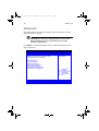
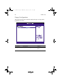
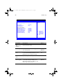
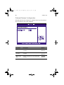
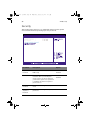
Main
The Main menu displays basic and important information about the
system. These information is necessary for troubleshooting and may
be required when asking for technical support.
The last two parameters on the screen lets you define the system’s time
and date settings. The real-time clock keeps the system date and time.
After setting the date and time, you do not need to enter them every
time you turn on the system. As long as the internal battery remains
good and connected, the clock continues to keep the date and time
accurately even when the power is off.
BIOS SETUP UTILITY
Main Advanced Power
AMIBIOS Version
BIOS Build Date
BIOS ID
System Time
System Date
:
:
:
Boot
Security
Exit
07.00.xx
08/09/02
S531A01
[14:21:40]
[Wed 08/09/2002]
ЧШ
ХЦ
+Tab
F1
F10
ESC
> System Information
> Product Information
Select Screen
Select Item
Change Option
Select Field
General Help
Save and Exit
Exit
V02.03 ©Copyright 1985-2000, American Megatrends Inc.
Parameter
Description
AMIBIOS Version
Version of the BIOS setup
BIOS Build Date
Date when the BIOS setup was created
BIOS ID
ID number of the BIOS setup
BB!H621!.!FO/cppl!!Qbhf!86!!Xfeoftebz-!Kbovbsz!9-!3114!!21;63!BN
75
Parameter
Description
System Time
Sets the time following the hour-minute-second
format. Valid values for hour, minute, and second
are:
Hour: 00 to 23
Minute: 00 to 59
Second: 00 to 59
System Date
Sets the date following the weekday-month-dayyear format. Valid values for weekday, month, day,
and year are:
Weekday: Sun, Mon, Tue, Wed, Thu, Fri, Sat
Month: 1to 12.
Day: 1 to 31
Year: 1980 to 2079
BB!H621!.!FO/cppl!!Qbhf!87!!Xfeoftebz-!Kbovbsz!9-!3114!!21;63!BN
76
4 BIOS setup
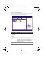
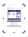
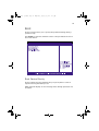
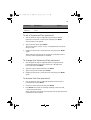
Advanced
The Advanced menu contains parameter values that define how the
system behaves on startup.
Warning! Be cautious in setting parameter values in the
Advanced menu as any incorrect value may cause the
system to malfunction.
Press Enter to enter the submenu screen of the parameters shown in
the screen below.
BIOS SETUP UTILITY
Main Advanced Power
Boot
Security
Setup Warning
Setting items on this screen to incorrect values
may cause the system to malfunction!
Exit
Configure SuperIO
Chipset Nat414
> SuperIO Configuration
> IDE Configuration
> Floppy Configuration
> PCIPnP Configuration
> Boot Settings Configuration
> Event Log Configuration
> OnBoard Devices Configuration
> Remote Access Configuration
ЧШ
ХЦ
Enter
F1
F10
ESC
Select Screen
Select Item
Go to Sub Screen
General Help
Save and Exit
Exit
V02.03 ©Copyright 1985-2000, American Megatrends Inc.
BB!H621!.!FO/cppl!!Qbhf!88!!Xfeoftebz-!Kbovbsz!9-!3114!!21;63!BN
77
Super I/O Configuration
The Super I/O Configuration submenu lets you define the parameter
settings for the system’s parallel and serial ports.
Parameter
Description
Serial Port 1
(Address/IRQ)
Serial port 1 address and IRQ (interrupt request) setting
Parallel Port
Address
Sets a logical base address for the parallel port
Parallel Port
IRQ
Assigns an IRQ for the parallel port.
Parallel Port
Mode
Sets the operation mode for the parallel port
If you install an add-on card that has a parallel port
whose address conflicts with the onboard parallel port, a
warning appears on the screen. Check the parallel port
address of the add-on card and change the address to
one that does not conflict.
BB!H621!.!FO/cppl!!Qbhf!89!!Xfeoftebz-!Kbovbsz!9-!3114!!21;63!BN
78
4 BIOS setup
Parameter
Description
ECP Mode DMA
Channel
Assigns a DMA (Direct Memory Access) channel for the
ECP (Extended Capabilities Port) parallel port function.
This parameter is configurable only if you select ECP as
the operation mode.
IDE Configuration
The IDE Configuration submenu lets you define the parameter settings
related to the hard disk/s.
Parameter
Description
Onboard PCI
IDE Controller
Selects which system IDE controller to enable
Primary IDE
Master
Press Enter to access the Primary IDE Master submenu.
Primary IDE
Slave
Press Enter to access the Primary IDE Slave submenu.
BB!H621!.!FO/cppl!!Qbhf!8:!!Xfeoftebz-!Kbovbsz!9-!3114!!21;63!BN
79
Parameter
Description
Secondary IDE
Master
Press Enter to access the Secondary IDE Master submenu.
Secondary IDE
Slave
Press Enter to access the Secondary IDE Slave submenu.
Hard Disk
Write Protect
Enables or disables the hard disk write protect function
Primary/Secondary IDE Master/Slave
These items let you select the IDE hard disk parameters that the system
supports.
Parameter
Description
Device
Type of IDE device
Vendor
Vendor of the selected IDE device
Option
BB!H621!.!FO/cppl!!Qbhf!91!!Xfeoftebz-!Kbovbsz!9-!3114!!21;63!BN
80
4 BIOS setup
Parameter
Description
Size
Size of the selected device
Type
Driver type
Option
Auto
CD-ROM
ARMD
Not Installed
LBA/Large
Mode
Selects the hard disk drive translation
method. For drivers with more than 504
MB, the LBA mode is necessary.
Auto
Block Mode
Enhances disk performance depending on
the hard disk in use.
If you set this parameter to Auto, BIOS
setup automatically detects if the
installed hard disk drive supports the
Block Mode function. If supported, it
allows data transfer in blocks (multiple
sectors) at a rate of 256 bytes per cycle.
Auto
Disabled
Disabled
If you set this parameter to Disabled, data
transfer from and to the device occurs
one sector at a time.
PIO Mode
DMA Mode
When set to Auto, BIOS setup
automatically detects if the installed hard
disk supports the function. If supported,
it allows for faster data recovery and
read/write timing that reduces hard disk
activity time. This results in better hard
disk performance. Mode 0 to 4 provide
successive increases in performance.
Auto
0
Selects DMA (Direct Memory Access)
mode. Options include:
Auto
Auto: Auto detected
SWDMAn: SingleWordDMAn
MWDMAn: MultiWordDMAn
UDMAn: UltraDMAn
1
2
3
4
SWDMAn
MWDMAn
UDMAn
BB!H621!.!FO/cppl!!Qbhf!92!!Xfeoftebz-!Kbovbsz!9-!3114!!21;63!BN
81
Parameter
Description
Option
S.M.A.R.T
Enables or disables the S.M.A.R.T (SelfMonitoring, Analysis and Reporting
Technology) function of the internal hard
disk.
If 'Auto' is selected, BIOS setup will
enable the S.M.A.R.T function if the
driver supports it.
Auto
Disabled
32-bit Data
Transfer
Enables or disables the 32-bit data
transfer function
Disabled
Enabled
ARMD
Emulation
Type
Selects the ARMD (ATAPI Removable
Media Device) emulation type
Auto
Enabled
Floppy
Hard Disk
BB!H621!.!FO/cppl!!Qbhf!93!!Xfeoftebz-!Kbovbsz!9-!3114!!21;63!BN
82
4 BIOS setup
Floppy Configuration
The Floppy Configuration submenu displays the type of floppy drive
installed in the server.
Parameter
Description
Option
Floppy Drive A
Floppy disk drive type
1.44 MB, 3.5-inch
None
BB!H621!.!FO/cppl!!Qbhf!94!!Xfeoftebz-!Kbovbsz!9-!3114!!21;63!BN
83
PCI/PnP Configuration
The PCI/PnP Configuration submenu lets you specify the settings for
the PCI devices.
Parameter
Description
Option
Plug & Play OS
When this parameter is set to Yes, BIOS
setup initializes only PnP boot devices such
as SCSI cards.
When set to No, the BIOS setup initializes
all PnP boot and non-boot devices such as
sound cards.
No
Yes
Note: Set this parameter to Yes only if the
operating system is Windows 95/98 or a
later version.
BB!H621!.!FO/cppl!!Qbhf!95!!Xfeoftebz-!Kbovbsz!9-!3114!!21;63!BN
84
4 BIOS setup
Parameter
Description
Option
Reset
Configure Data
BIOS setup stores the configuration data of
Plug and Play devices in NVRAM (Non-volatile Random Access Memory).
When this parameter is set to Yes, current
data is deleted and a new set of information is created during the next system
bootup.
No
Yes
PCI Latency
Timer
Sets a timing parameter for the PCI bus.
64
USB Function
Enables the system’s USB ports
Enabled
Disabled
Legacy USB
Support
Enable this parameter when you intend to
use a USB device and are using a non-Plug
and Play operating system, such as DOS.
Disabled
Auto
ARMD
Emulation Type
Selects the ARMD (ATAPI Removable
Media Device) emulation type.
Hard Disk
Auto
Floppy
BB!H621!.!FO/cppl!!Qbhf!96!!Xfeoftebz-!Kbovbsz!9-!3114!!21;63!BN
85
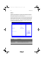
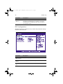
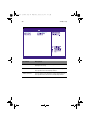
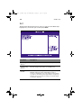
Boot Settings Configuration
The Boot Settings Configuration submenu lets you specify the
preferred settings for system bootup.
B IO S S E T U P U T IL IT Y
Advanced
B o o t S e ttin g s C o n fig u r a tio n
A llo w s B IO S to s k ip
____________________________________________________
c e r ta in te s ts w h ile
Q u ic k B o o t
[E n a b le d ]
b o o tin g . T h is w ill
Q u ie t B o o t
[E n a b le d ]
d e c r e a s e th e tim e
____________________________________________________
n e e d e d to b o o t th e
H y p e r T h r e a d in g
[E n a b le d ]
s y s te m .
A u to -d e te c t C P U F re q u e n c y
[E n a b le d ]
C P U F r e q u e n c y to B u s R a tio
[2 1 to 1 ]
B o o tu p N u m -L o c k
[O n ]
P S /2 M o u s e S u p p o r t
[E n a b le d ]
W a it F o r ‘F 1 ’If E r r o r
[E n a b le d ]
M P S 1 .4 S u p p o r t
[E n a b le d ]
M e m o ry Te s t
[E n a b le d ]
Ч Ш
S e le c t S c r e e n
Х Ц
S e le c t Ite m
+ -
C h a n g e O p tio n
F1
G e n e r a l H e lp
F10
S a v e a n d E x it
ESC
E x it
V 0 2 .0 3 © C o p y r ig h t 1 9 8 5 -2 0 0 0 , A m e r ic a n M e g a tr e n d s In c .
Parameter
Description
Option
Quick Boot
Allows the system to boot faster by
skipping some POST routines.
Enabled
Disabled
BB!H621!.!FO/cppl!!Qbhf!97!!Xfeoftebz-!Kbovbsz!9-!3114!!21;63!BN
86
4 BIOS setup
Parameter
Description
Option
Quiet Boot
Enables or disables the Quiet Boot function. When set to Enabled, BIOS setup is in
graphical mode and displays only an identification logo during POST and while
booting. After booting, the screen displays
the operating system prompt (such as DOS)
or logo (such as Windows). If any error
occurs while booting, the system
automatically switches to text mode.
Enabled
Disabled
Even if your setting is Enabled, you may
still switch to text mode while booting by
pressing the CTRL-ALT-ESC key when you
see the "Press CTRL-ALT-ESC key to enter
setup" message on the screen.
When set to Disabled, BIOS setup is in the
conventional text mode where you see the
system initialization details on the screen.
Hyperthreading
Enable or disables the hyperthreading
function of the processor.
Enabled
Disabled
When enabled, one physical processor acts
as two logical processors by "threading"
two sets of data instructions in parallel
streams for processing. The processor can
then simultaneously manage incoming
data from different applications without
losing track of the data processing status
of each.
Auto-Detect
CPU Frequency
BIOS will set the CPU optimal speed to its
highest speed without re-entering BIOS
Setup to load default settings.
Enabled
Boot up
Num Lock
Activates the Num Lock function upon
booting
On
Off
CPU Frequency
to Bus Ratio
CPU/bus ratio of the system. The clock
speed of the bus does not necessarily equal
the CPU’s. Mostly, the bus clock speed is
slower than the CPU clock speed.
21 to 1
PS/2 Mouse
Support
Enable this parameter if you intend to use
a mouse or trackball with a PS/2 interface.
Enabled
Disabled
BB!H621!.!FO/cppl!!Qbhf!98!!Xfeoftebz-!Kbovbsz!9-!3114!!21;63!BN
87
Parameter
Description
Option
Wait for 'F1' if
Error
When this item is enabled you will be
prompted to press F1 when an error is
detected during boot up.
Enabled
Disabled
MPS 1.4
Support
If you enable this item, the system BIOS MP
table will be compatible with
MultiProcessor Specification version 1.4 .
Enabled
Disabled
Memory Test
Allows BIOS to skip certain tests while
booting. Thie will dercrease the time
needed to boot the system.
Enabled
Disabled
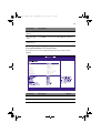
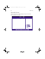
Event Log Configuration
The Event Log Configuration submenu lets you specify the appropriate
settings for the system’s event handling function.
The system event log enables you to record and monitor events that
occur in the system (e.g., system temperature changes, fan stops, etc.).
BB!H621!.!FO/cppl!!Qbhf!99!!Xfeoftebz-!Kbovbsz!9-!3114!!21;63!BN
88
4 BIOS setup
BIOS SETUP UTILITY
Advanced
ENABLED: Allow logging
ASF Information
____________________________________________________ of events.
ASF Specification Version
1.03
Event Logging
Clear All Event Logs
> View Event Log
Event Control Interface
BIOS POST Event Logging
ECC Event Logging
PCI Device Event Logging
AC Power Lost/Recovery
Intrusion Event Logging
Clear Intrusion Status
Reset Reduction Memory
[Enabled]
[No]
[Enabled]
[Enabled]
[Enabled]
[Disabled]
[Enabled]
[No]
[No]
ЧШ
ХЦ
+F1
F10
ESC
Select Screen
Select Item
Change Option
General Help
Save and Exit
Exit
V02.03 ©Copyright 1985-2000, American Megatrends Inc.
Parameter
Description
Option
ASF
Specification
Version
Version number of ASF
Event Logging
Enables or disables the event logging function of the system
Enabled
Disabled
Clear All Event
Logs
When this item is set to Enabled, the event
log is cleared and this parameter is set to
Disabled for the next system bootup.
No
View Event
Logs
Opens the system event log file for viewing
BIOS POST
Event Logging
BIOS checks the bad processors and memory modules during the POST process.
When this parameter is enabled, it will
make a log of this operation.
Yes
Enabled
Disabled
BB!H621!.!FO/cppl!!Qbhf!9:!!Xfeoftebz-!Kbovbsz!9-!3114!!21;63!BN
89
Parameter
Description
Option
ECC Event
Logging
ECC (Error Correcting Code) tests the accuracy of data as it passes in and out of memory. When this parameter is enabled,
single-bit and multi-bit memory errors will
be recorded in the event log.
Enabled
Disabled
PCI Device
Event Logging
PCI (Peripheral Component Interconnect) is
a 32-bit bus that supports a 64-bit extension for new processors, such as Pentium
processors. It can run at clock speeds of 33
or 66 MHz. When this
parameter is enabled, any PCI device error
will be recorded in the event log.
Enabled
AC Power
Lost/Recovery
When this parameter is enabled, any
instance of AC power lost will be monitored and logged in the event log.
Disabled
Enabled
Intrusion
Event Logging
Allow logging of chassis intrusion events.
Enabled
Clear Intrusion Status
Clear chassis intrusion status on next Boot.
Yes
Reset Reduction Memory
When this parameter is enabled, only the
the system’s healthy memory size is displayed during the POST process.
Disabled
No
No
Yes
BB!H621!.!FO/cppl!!Qbhf!:1!!Xfeoftebz-!Kbovbsz!9-!3114!!21;63!BN
90
4 BIOS setup
Onboard Devices Configuration
The Onboard Devices Configuration submenu lets you specify settings
that are related to the system hardware.
Parameter
Description
Option
Onboard LAN
Enables or disables the onboard LAN
controller
Enabled
Disabled
Onboard SCSI
Controller
Enables or disables the onboard SCSI
controller
Enabled
Onboard PCI
VGA
Enables or disables the onboard PCI VGA
controller
Enabled
Disabled
Disabled
BB!H621!.!FO/cppl!!Qbhf!:2!!Xfeoftebz-!Kbovbsz!9-!3114!!21;63!BN
91
Power
The Power menu allows you to configure the system’s power
management feature.
Parameter
Description
Option
ACPI-aware O/S
This parameter indicates whether the system’s OS support the ACPI (Advanced Configuration and Power Interface) standard
of power management.
Yes
No
Power
Management
When this parameter is enabled, it allows
some OS, such as Windows 95/98, to implement APM (Advanced Power Management) functions.
Enabled
Disabled
BB!H621!.!FO/cppl!!Qbhf!:3!!Xfeoftebz-!Kbovbsz!9-!3114!!21;63!BN
92
4 BIOS setup
Parameter
Description
Option
AC Power
Failure
Defines the power state to resume to after
a system shutdown that is due to an interruption in AC power.
When set to Last State, the system will
return to the active power state prior to
shutdown.
Last State
Stay Off
When set to Stay Off, the system remains
off after power shutdown.
Power Button
Mode
When set to On/Off, the power button
serves as a standard on/off button.
When set to Suspend, pressing the power
button will activate the power-saving suspend mode.
On/Off
Suspend
BB!H621!.!FO/cppl!!Qbhf!:4!!Xfeoftebz-!Kbovbsz!9-!3114!!21;63!BN
93
Boot
The Boot menu allows you to specify the preferred settings during
system bootup.
Press Enter to enter the submenu screen of the parameters shown in
the screen below.
Boot Device Priority
The Boot Device Priority submenu lets you specify the boot search
sequence during the POST process.
BIOS setup will display an error message if the drive(s) specified is not
bootable.
BB!H621!.!FO/cppl!!Qbhf!:5!!Xfeoftebz-!Kbovbsz!9-!3114!!21;63!BN
94
4 BIOS setup
Parameter
Description
1st Boot Device
Sets the device from which the system will first
attempt to boot up.
2nd Boot Device
Sets the device from which the system will attempt to
boot up when the first attempt failed.
3rd Boot Device
Sets the device from which the system will attempt to
boot up when the first and second attempts failed.
BB!H621!.!FO/cppl!!Qbhf!:6!!Xfeoftebz-!Kbovbsz!9-!3114!!21;63!BN
95
Hard Disk Drives
The Hard Disk Drives submenu lets you specify the devices that will be
considered as the primary and secondary hard drives.
Parameter
Description
1st Hard Drive
Sets the device to be considered the primary hard
drive.
2nd Hard Drive
Sets the device to be considered the secondary hard
drive.
BB!H621!.!FO/cppl!!Qbhf!:7!!Xfeoftebz-!Kbovbsz!9-!3114!!21;63!BN
96
4 BIOS setup
Removable Devices
The Removable Devices submenu displays the type of removable
devices available in the system.
BB!H621!.!FO/cppl!!Qbhf!:8!!Xfeoftebz-!Kbovbsz!9-!3114!!21;63!BN
97
ATAPI CD-ROM Devices
The ATAPI (Advanced Technology Attachment Packet Interface)
CD-ROM submenu displays the type of ATAPI CD-ROM available in the
system.
BIOS SETUP UTILITY
Boot
st
1 ATAPI CDROM [IDE SECONDARY MASTER - xxx]
Specifies the boot
sequence from the
available devices.
àß
áâ
+F1
F10
ESC
Select Screen
Select Item
Change Option
General Help
Save and Exit
Exit
V02.03 ©Copyright 1985-2000, American Megatrends Inc.
BB!H621!.!FO/cppl!!Qbhf!:9!!Xfeoftebz-!Kbovbsz!9-!3114!!21;63!BN
98
4 BIOS setup
Security
The Security menu allows you to safeguard and protect the system
from unauthorized use by setting up access passwords.
Parameter
Description
Option
Supervisor
Password
Prevents unauthorized access to the
BIOS setup
Not Installed
Installed
User Password
Secures your system against unauthorized use. Once you set this password, you have to type it whenever
you boot the system. User password
is available only when a Supervisor
password is set.
Not Installed
Installed
Change User
Password
Press Enter to change the User password.
Change
Supervisor
Password
Press Enter to change the Supervisor
password.
BB!H621!.!FO/cppl!!Qbhf!::!!Xfeoftebz-!Kbovbsz!9-!3114!!21;63!BN
99
Parameter
Description
Clear User
Password
Press Enter to remove the User password.
Option
To set a Supervisor/User password
1
Use the up/down keys to highlight a password parameter
(Supervisor Password or User Password) then press Enter.
A password box will appear.
2
Type a password then press Enter.
The password may consist of up to six alphanumeric characters
(A-Z, a-z, 0-9).
3
Retype the password to verify the first entry then press Enter
again.
After setting the password, the system automatically sets the
chosen password parameter to Installed.
To change the Supervisor/User password
1
Use the up/down keys to highlight either change password
parameters (Change Supervisor Password or Change User
Password) then press Enter.
2
Type the original password then press Enter.
3
Type a new password then press Enter.
4
Retype the password to verify the first entry then press Enter
again.
To remove the User password
1
Use the up/down keys to highlight the Clear User Password
parameter then press Enter.
2
Enter the current password then press Enter.
3
Press Enter twice without entering anything in the new and
confirm password fields.
After doing this, the system automatically sets the User password
parameter to Not Installed.
BB!H621!.!FO/cppl!!Qbhf!211!!Xfeoftebz-!Kbovbsz!9-!3114!!21;63!BN
100
4 BIOS setup
Exit
The Exit menu displays the various options to quit from the BIOS setup.
Highlight any of the exit options then press Enter.
Parameter
Description
Exit Saving
Changes
Saves changes made and close the BIOS setup
Exit Discarding
Changes
Discards changes made and close the BIOS setup
Load Optimal
Defaults
Loads the optimal settings for all BIOS setup parameters.
Optimal settings are quite demanding in terms of
resources consumption. If you are using low-speed memory chips or other kinds of low-performance components
and you choose to load these settings, the system might
not function properly.
BB!H621!.!FO/cppl!!Qbhf!212!!Xfeoftebz-!Kbovbsz!9-!3114!!21;63!BN
101
Parameter
Description
Load Failsafe
Defaults
Loads the failsafe settings for all BIOS parameters.
Failsafe settings, compared to the optimal settings, are
not quite as demanding in terms of resources consumption so you can be sure to have a stable system performance even if you are using
low-grade components.
Discard
Changes
Discards all changes made on the BIOS setup.
BB!H621!.!FO/cppl!!Qbhf!213!!Xfeoftebz-!Kbovbsz!9-!3114!!21;63!BN
102
4 BIOS setup
BB!H621!.!FO/cppl!!Qbhf!214!!Xfeoftebz-!Kbovbsz!9-!3114!!21;63!BN
Appendix A: ASM
Quick Installation
Guide
BB!H621!.!FO/cppl!!Qbhf!215!!Xfeoftebz-!Kbovbsz!9-!3114!!21;63!BN
This appendix shows you how to install the
ASM software package.
BB!H621!.!FO/cppl!!Qbhf!216!!Xfeoftebz-!Kbovbsz!9-!3114!!21;63!BN
105
Installing ASM
Acer Server Manager (ASM) consists of the ASM Console and the ASM
Agent. These two components are both required to perform server
management tasks.
System requirements
ASM requires TCP/IP connectivity between the ASM Console and the
ASM Agent.
ASM Agent
•
Altos Server System
•
Min. of 128 MB RAM
•
SCSI/IDE hard drive with at least 100 MB free hard disk space
•
Microsoft Windows NT 4.0 or Windows 2000 Server/Advanced
Server operating system
ASM Console
•
Intel Pentium III (500 MHz) or higher processor
•
128 MB of RAM
•
SCSI/IDE hard drive with at least 100 MB free hard disk space
•
Microsoft Windows 2000 Professional/XP/Server/Advanced Server
operating system
•
Ethernet card
System setup
Make sure that your system meets the requirements listed above
before proceeding. You may also want to change your screen to
800 x 600 resolution or higher for optimum viewing.
BB!H621!.!FO/cppl!!Qbhf!217!!Xfeoftebz-!Kbovbsz!9-!3114!!21;63!BN
106
Appendix A: ASM Quick Installation Guide
Installing ASM Agent
To install ASM Agent:
1
Log in to the managed server using the Administrator account.
2
Insert the EasyBUILDTM Management CD into the server’s CD-ROM
drive.
The installation sequence will automatically be displayed.
3
Select the option for ASM installation.
The installation wizard will be initialized.
4
Follow all onscreen instructions to complete installation.
For detailed instructions on installing ASM Agent, refer to the
ASM User’s manual.
To launch the program, on the Windows taskbar click on the Start
button, point to Programs, select Acer Server Management Suite
then click ASM Agent.
Installing ASM Console
To install ASM Console:
1
Log in to the target Windows-based PC using the Administrator
account.
2
Insert the EasyBUILDTM Management CD into the computer’s
CD-ROM drive.
The installation sequence will automatically be displayed.
3
Select the option for ASM installation.
The installation wizard will be initialized.
4
Follow all onscreen instructions to complete installation.
For detailed instructions on installing ASM Console, refer to the
ASM User’s manual.
To launch the program, on the Windows taskbar click on the Start
button, point to Programs, select Acer Server Management Suite
then click ASM Console.
BB!H621!.!FO/cppl!!Qbhf!218!!Xfeoftebz-!Kbovbsz!9-!3114!!21;63!BN
Appendix B: Altos
G510 Rack Installation
Guide
BB!H621!.!FO/cppl!!Qbhf!219!!Xfeoftebz-!Kbovbsz!9-!3114!!21;63!BN
This appendix shows you how to install the
optional rack mount kit for Acer Altos G510.
BB!H621!.!FO/cppl!!Qbhf!21:!!Xfeoftebz-!Kbovbsz!9-!3114!!21;63!BN
109
System rack installation
Aside from its tower configuration, the Altos G510 server system can
also be mounted in a rack-model position. A rack mount kit is
available for customers who want to mount a server tower system in a
server rack. To purchase a rack mount kit, contact your local Acer
representative or order directly from Acer.com.
The figure below shows the Altos G510 mounted in as a rack server
Vertical mounting hole pattern
BB!H621!.!FO/cppl!!Qbhf!221!!Xfeoftebz-!Kbovbsz!9-!3114!!21;63!BN
110
Appendix B: Altos G510 Rack Installation Guide
The four vertical rails of a rack contain mounting holes arranged in a
manner shown in the figure below:
The system occupies 5U in the rack. Count the U positions and hole
numbers from the bottom up.
Note: The unit of measurement used in this document is "U"
(1U = 1.75 inches or 44.45 mm). The total sum of the heights of all
components in the rack measured in "U" cannot exceed the
height of the rack. For more information, refer to the
documentation that came with your system rack.
The distance from the center of two holes with closer spacing to the
center of the next pair is equivalent to 1U.
When installing components, you must start your measurement from
the center of the two holes with closer spacing. Otherwise, the screw
holes on the component may not match those on the rack.
BB!H621!.!FO/cppl!!Qbhf!222!!Xfeoftebz-!Kbovbsz!9-!3114!!21;63!BN
111
Screw types for rack installation
The following screws are used in the mounting process for the Acer
Altos G510 and other rack-mount components.
Screw type
Figure
Usage
1
#8-32 x 0.25 inch
Securing the inner mounting
rails to the server
2
Hex head
#6-32 0.25 inch
Attaching the side handles to
the server
3
M4 x L8
Securing the mounting
brackets to the inner sliding
piece
M4 nut
4
M6 x L10
Securing the cable carrier
and the mounting rails to the
rack
Cage nut
Supports the M6 metal
screws for securing server
components to the rack
BB!H621!.!FO/cppl!!Qbhf!223!!Xfeoftebz-!Kbovbsz!9-!3114!!21;63!BN
112
Appendix B: Altos G510 Rack Installation Guide
Installing the system into the rack
To install the system into the rack:
1
Remove the front bezel from the server. Refer to page 40 for
detailed instructions.
2
Remove the top panel of the server.
3
(1)
Remove the two rear screws that secure the top panel to the
chassis.
(2)
Slide the top panel backward to detach it from the chassis.
Remove the stands from the server.
(1)
Lay the server on its side on a flat, stable surface.
(2)
Remove the single screw from the center of each of the
server’s four stands. Keep these for later use.
BB!H621!.!FO/cppl!!Qbhf!224!!Xfeoftebz-!Kbovbsz!9-!3114!!21;63!BN
113
(3)
Gently twist and pull the stands from the server.
The Rack Mount Kit contains two sets of rack brackets and mounting
rails. The rack brackets attach the mounting rails to the server. Each
bracket is composed of three pieces: a detachable inner rail and a fixed
middle and outer rails. The mounting rails hold the server in the
brackets and allow the system to slide in and out of the rack for
maintenance or upgrading purposes.
4
Remove the inner rail from the rack brackets.
(1) Extend the inner rail until the rail release latch clicks.
(2) Press the release latch then slip the inner rail out.
BB!H621!.!FO/cppl!!Qbhf!225!!Xfeoftebz-!Kbovbsz!9-!3114!!21;63!BN
114
Appendix B: Altos G510 Rack Installation Guide
Do the same thing with the other rack bracket.
5
Attach the inner rails to the top and bottom (sides) of the server
with the release catches toward the front of the system.
(1)
Align the inner rail to the five screw holes located on the
bottom of the server.
(2) Secure the rail to the server using #8-32 (1 on page 113)
screws.
Attach the other inner rail to the top side of the server.
BB!H621!.!FO/cppl!!Qbhf!226!!Xfeoftebz-!Kbovbsz!9-!3114!!21;63!BN
115
6
Attach the two side handles to the server using two hex head (2 on
page 113) screws for each handle.
7
Set the server aside.
8
Attach the rack brackets to the mounting rails.
a
Align the rack brackets to the mounting rail until the six screw
holes become visible.
b
Secure the rack bracket to the mounting rail using M4 x L8 (3
on page 113) screws and M4 nuts. Tighten the screws, but
BB!H621!.!FO/cppl!!Qbhf!227!!Xfeoftebz-!Kbovbsz!9-!3114!!21;63!BN
116
Appendix B: Altos G510 Rack Installation Guide
leave them loose enough to allow length adjustment when
installing the mounting rails to the rack.
Attach the other rack brackets to the remaining mounting rail.
9
Install the mounting rails to the rack using four M6 x L10 (4 on
page 113) screws and cage nuts (two at each end) for each
mounting rail.
Installing cage nuts
Cage nuts are used to secure system and other components to the
vertical rails in the rack.
To install cage nuts:
•
Insert the lower lip of the cage nut over the bottom of the
opening at the back of a rail.
•
With your fingers, pinch the cage nut rack fastener and push
in until the top lip locks into position.
•
Repeat this process to install the other cage nuts in their
appropriate locations.
BB!H621!.!FO/cppl!!Qbhf!228!!Xfeoftebz-!Kbovbsz!9-!3114!!21;63!BN
117
BB!H621!.!FO/cppl!!Qbhf!229!!Xfeoftebz-!Kbovbsz!9-!3114!!21;63!BN
118
Appendix B: Altos G510 Rack Installation Guide
10 Extend the middle sliding piece of each mounting rail forward
until it clicks.
11 Install the server into the rack by first carefully aligning the inner
rails attached to the server with the fully extended middle
mounting rails on the rack.
(1)
(2)
Press the release latch on both sides of the server.
Slide the server into the rack then push the server into the
rack until it clicks.
BB!H621!.!FO/cppl!!Qbhf!22:!!Xfeoftebz-!Kbovbsz!9-!3114!!21;63!BN
119
Caution! To avoid personal injury, care should be taken when
pressing the component rail release latches and sliding the
component into the rack.
12 Attach the Cable Arm
The optional Cable Arm keeps peripheral and power cables from
becoming tangled or severed when the system slides in or out.
(1)
Attach the cable arm to the back of the!server!with!two!
M4 x L8!(3 on page 113) screws and two nuts.
BB!H621!.!FO/cppl!!Qbhf!231!!Xfeoftebz-!Kbovbsz!9-!3114!!21;63!BN
120
Appendix B: Altos G510 Rack Installation Guide
(2)
Install two cage nuts in the rail to which the cable arm is to
be attached. Extend the cable arm enough to attach it to
the rail using two M6 x L10 (4 on page 113) screws.
(3)
Insert the power, peripheral and networking cables into the
appropriate ports. Refer to ”Connecting peripherals” on
page 22 for detailed instructions.
(4)
Bundle all cables to the cable carrier with the cable clamps.
BB!H621!.!FO/cppl!!Qbhf!232!!Xfeoftebz-!Kbovbsz!9-!3114!!21;63!BN
121
(5)
The cable arm will protect the cables when the system is
being moved into or out of the server rack.
BB!H621!.!FO/cppl!!Qbhf!233!!Xfeoftebz-!Kbovbsz!9-!3114!!21;63!BN
122
Appendix B: Altos G510 Rack Installation Guide
BB!H621!.!FO/cppl!!Qbhf!234!!Xfeoftebz-!Kbovbsz!9-!3114!!21;63!BN
123
Index
A
Acer Server Manager (ASM) 105
system requirements 105
ASM Agent 105
ASM Console 105
system setup 105
install ASM Agent 106
install ASM Console 106
B
BIOS setup 71
Advanced 76
Boot Settings Configuration
85
Event Log Configuration
87
Floppy Configuration 82
IDE Configuration 78
Primary/Secondary IDE
Master/Slave
79
Onboard Devices Configuration 90
PCI/PnP Configuration 83
Super I/O Configuration 77
Boot 93
ATAPI CD-ROM Devices 97
Boot Device Priority 93
Hard Disk Drives 95
Removable Devices 96
entering 72
Exit 100
Main 74
Power 91
Security 98
changing a password 99
removing the User password 99
Supervisor password 98
User password 98
BPL4 cage configuration 44
installing cage 47
installing hard disk 45
removing cage 44
C
CPU
installing 57
removing 56
D
DIMM
installing 61
removing 60
E
expansion card
installing 62
O
opening the system 39
open front bezel 39
remove air baffle 43
remove front bezel 40
remove side panel 41, 42
P
peripherals 22
keyboard 22
monitor 24
printer 25
power cable 26
power supply module
installing 65
S
SCSI cable cage configuration 49
installing cage 51
installing hard disk 50
removing cage 51
system boards 14
BPL4 board layout 17
mainboard layout 14
system memory
reconfiguring 61
system upgrade 37
ESD precautions 37
post-installation instructions 38
preinstallation instructions 37
T
turning off the system 32
turning on the system 27
power-on problems 28
BB!H621!.!FO/cppl!!Qbhf!235!!Xfeoftebz-!Kbovbsz!9-!3114!!21;63!BN
124