1
Acer Altos G320 Series
User’s Guide
Copyright © 2005 Acer Incorporated
All Rights Reserved.
Acer Altos G320 Series
User’s Guide
Changes may be made periodically to the information in this publication without obligation
to notify any person of such revision or changes. Such changes will be incorporated in new
editions of this manual or supplementary documents and publications. This company makes
no representations or warranties, either expressed or implied, with respect to the contents
hereof and specifically disclaims the implied warranties of merchantability or fitness for a
particular purpose.
Record the model number, serial number, purchase date, and place of purchase information in
the space provided below. The serial number and model number are recorded on the label
affixed to your computer. All correspondence concerning your unit should include the serial
number, model number, and purchase information.
No part of this publication may be reproduced, stored in a retrieval system, or transmitted, in
any form or by any means, electronic, mechanical, photocopy, recording, or otherwise,
without the prior written permission of Acer Incorporated.
Acer Altos G320 Series
Model Name :
Part Number:
Purchase Date:
Place of Purchase:
Acer and the Acer logo are registered trademarks of Acer Inc. Other company’s product names
or trademarks are used herein for identification purposes only and belong to their respective
companies.
iii
Notices
FCC notice
Class A devices do not have an FCC logo or FCC IDE on the label. Class B devices
have an FCC logo or FCC IDE on the label. Once the class of the device is
determined, refer to the following corresponding statement.
Class A equipment
This device has been tested and found to comply with the limits for a Class A
digital device pursuant to Part 15 of the FCC Rules. These limits are designed to
provide reasonable protection against harmful interference when the
equipment is operated in a commercial environment. This equipment
generates, uses, and can radiate radio frequency energy, and if not installed
and used in accordance with the instructions, may cause harmful interference to
radio communications. Operation of this equipment in a residential area is
likely to cause harmful interference, in which case the user will be required to
correct the interference at personal expense.
Class B equipment
This device has been tested and found to comply with the limits for a Class B
digital device pursuant to Part 15 of the FCC Rules. These limits are designed to
provide reasonable protection against harmful interference in a residential
installation. This device generates, uses, and can radiate radio frequency
energy, and if not installed and used in accordance with the instructions, may
cause harmful interference to radio communications.
However, there is no guarantee that interference will not occur in a particular
installation. If this device does cause harmful interference to radio or television
reception, which can be determined by turning the device off and on, the user
is encouraged to try to correct the interference by one or more of the following
measures:
•
Reorient or relocate the receiving antenna
•
Increase the separation between the device and receiver
•
Connect the device into an outlet on a circuit different from that to which
the receiver is connected
•
Consult the dealer or an experienced radio/television technician for help
iv
Notice: Shielded cables
All connections to other computing devices must be made using shielded cables
to maintain compliance with FCC regulations.
Notice: Peripheral devices
Only peripherals (input/output devices, terminals, printers, etc.) certified to
comply with the Class A or Class B limits may be attached to this equipment.
Operation with noncertified peripherals is likely to result in interference to
radio and TV reception.
Caution! Changes or modifications not expressly approved by the
manufacturer could void the user’s authority, which is granted by
the Federal Communications Commission, to operate this server.
Use conditions
This part complies with Part 15 of the FCC Rules. Operation is subject to the
following two conditions: (1) this device may not cause harmful interference,
and (2) this device must accept any interference received, including interference
that may cause undesired operation.
Notice: Canadian users
This Class A/Class B digital apparatus meets all requirements of the Canadian
Interference-Causing Equipment Regulations.
Laser compliance statement
The DVD-ROM or CD/DVD combo drive in this server is a laser product. The
drive’s classification label (shown below) is located on the drive.
CLASS 1 LASER PRODUCT
CAUTION: INVISIBLE LASER RADIATION WHEN OPEN. AVOID EXPOSURE TO
BEAM.
v
Important safety instructions
Read these instructions carefully. Save these instructions for future reference.
1
Follow all warnings and instructions marked on the product.
2
Unplug this product from the wall outlet before cleaning. Do not use
liquid cleaners or aerosol cleaners. Use a damp cloth for cleaning.
3
Do not use this product near water.
4
Do not place this product on an unstable cart, stand, or table. The product
may fall, causing serious damage to the product.
5
Slots and openings on the back or bottom side of the chassis are provided
for ventilation; to ensure reliable operation of the product and to protect
it from overheating, these openings must not be blocked or covered. The
openings should never be blocked by placing the product on a bed, sofa,
rug, or other similar surface. This product should never be placed near or
over a radiator or heat register, or in a built-in installation unless proper
ventilation is provided.
6
This product should be operated from the type of power indicated on the
marking label. If you are not sure of the type of power available, consult
your dealer or local power company.
7
Do not allow anything to rest on the power cord. Do not locate this
product where persons will walk on the cord.
8
If an extension cord is used with this product, make sure that the total
ampere rating of the equipment plugged into the extension cord does not
exceed the extension cord ampere rating. Also, make sure that the total
rating of all products plugged into the wall outlet does not exceed the fuse
rating.
9
Never push objects of any kind into this product through chassis slots as
they may touch dangerous voltage points or short out parts that could
result in a fire or electric shock. Never spill liquid of any kind on the
product.
10
Do not attempt to service this product yourself, as opening or removing
covers may expose you to dangerous voltage points or other risks. Refer all
servicing to qualified service personnel.
11
Unplug this product from the wall outlet and refer servicing to qualified
service personnel under the following conditions:
a
When the power cord or plug is damaged or frayed
b
If liquid has been spilled on the product
c
If the product has been exposed to rain or water
vi
d
If the product does not operate normally when the operating
instructions are followed. Adjust only those controls that are covered
by the operating instructions since improper adjustment of other
controls may result in damage and will often require extensive work
by a qualified technician to restore the product to normal condition.
e
If the product has been dropped or the cabinet has been damaged
f
If the product exhibits a distinct change in performance, indicating a
need for service.
12
Replace the battery with the same type as the product's battery we
recommend. Use of another battery may present a risk of fire or explosion.
Refer battery replacement to a qualified service technician.
13
Warning! Batteries may explode if not handled properly. Do not
disassemble or dispose of them in fire. Keep them away from children and
dispose of used batteries promptly.
14
Use only the proper type of power supply cord set (provided in your
accessories box) for this unit. It should be a detachable type: UL listed/CSA
certified, type SPT-2, rated 7A 125V minimum, VDE approved or its
equivalent. Maximum length is 15 feet (4.6 meters).
iii
iii
iv
v
1 System tour
1
Features summary
External and internal structure
Front panel
Rear panel
Internal components
Mainboard layout
Jumper settings
Maintenance mode jumper
Clear CMOS jumper
2 System setup
Setting up the system
Pre-installation requirements
Connecting peripherals
Turning on the system
Power-on problems
Turning off the system
3 System upgrade
Installation precautions
ESD precautions
Pre-installation instructions
Post-installation instructions
Opening the server
Removing the left-side panel
Unlocking the front bezel
Removing the front bezel
Installing and removing storage devices
Installing and removing a hard disk
Upgrading the processor
Removing the HSFD assembly
Removing the CPU
Installing the CPU
Installing the HSFD assembly
Upgrading the system memory
3
6
6
8
10
11
13
13
14
15
17
17
18
19
20
21
23
25
25
25
26
27
27
28
28
29
31
33
33
34
34
35
37
Contents
Notices
FCC notice
Laser compliance statement
Important safety instructions
viii
Memory module installation guidelines
Removing a DIMM
Installing a DIMM
Installing an expansion card
4 BIOS setup
BIOS setup
Entering BIOS setup
Main
Advanced
Boot Configuration
Peripheral Configuration
Drive Configuration
Floppy Configuration
Event Log Configuration
Video Configuration
Hardware Monitoring
Chipset Configuration
USB Configuration
Security
Setting the Supervisor/User password:
Power
Boot
Exit
5 Troubleshooting
Troubleshooting
Resetting the system
Problems following initial system installation
First steps checklist
Hardware diagnostic testing
Verifying proper operation of key system lights
Specific problems and corrective actions
BIOS POST error beep codes
Troubleshooting BIOS POST error beep codes
Appendix A: System management utility
Overview
ASM
System requirements
System setup
37
39
39
41
43
45
46
48
51
52
53
54
56
57
58
59
60
61
62
63
64
66
68
71
73
73
73
74
75
75
76
84
84
87
89
90
90
91
ix
RAID configuration utility
SATA RAID configuration utility
SCSI RAID configuration utility
92
92
92
Appendix B: SATA RAID configuration
93
Overview
Features
Configuring arrays
RAID CU (configuration utility)
Using the RAID CU
Configuring arrays and logical drives
Configuration guidelines
Quick configuration
Detailed configuration
Initializing logical drives
Rebuilding failed disks
Checking data consistency
Troubleshooting
Problems and suggested solutions
95
95
97
100
100
102
102
103
104
107
109
110
111
111
Appendix C: SCSI RAID configuration
Configuring the SCSI/SCSI RAID HBA
Using the SCSI HBA setup utility
Using the MegaRAID configuration utility
Index
113
115
115
117
119
x
1 System tour
The Acer Altos G320 server is an entry level
single-processor general purpose system. The
system offers a new standard for flexible
productivity ideal for small business or
workgroup applications.
3
Features summary
Listed below are the system’s key features:
Processor
•
Single LGA775 socket supporting the following Intel® processors:
•
Pentium D processor
•
Pentium 4 processor
•
Celeron D processor
•
256 KB, 1 MB, 2 MB or 2x1 MB L2 cache
•
800 or 533 MHz FSB
•
Supports the following Intel technology 1:
•
Intel Dual Core Architecture
•
Supports Intel Hyper-Threading Technology
•
Supports Intel EM64T (Extended Memory 64 Technology)
Chipset
•
Intel E7230 MCH (Memory Controller Hub)
•
Intel ICH7R I/O controller
Memory
•
Four DIMM sockets for a maximum memory capacity of 8 GB
•
Supports 512 MB, 1 GB, and 2 GB DDR2-533/667 MHz ECC
unbuffered memory modules
•
Supports dual-channel interleave operation
Note: Dual-channel memory requires that only DIMM modules of
identical type, banking, stacking technology and manufacturer
can be installed in the Altos G320 system.
1 Support for dual core configuration, Hyper-Threading Technology and EM64T may vary
depending on processor-type specifications.
4
1 System tour
Media storage
•
3.5-inch, 1.44 MB floppy drive
•
DVD-ROM or combo drive
•
Three 5.25-inch device bays for add-on options:
•
DAT72 tape drive
•
AIT tape drive
Optional media storage
•
Supports up to four SATA or SCSI hard disk drives
SATA controller
•
Onboard SATA: Intel ICH7R I/O controller supports four SATA ports
that offer data transfer rates of up to 3.0 Gbps
•
Supports software RAID 0, 1, and 10 for onboard SATA ports
Networking
•
Intel 82541Pl Gigabit Ethernet controller
•
Intel 82573V Gigabit Ethernet controller
PCI I/O
•
Five PCI bus slots with three separate bus segments:
•
Two PCI bus slots (32-bit/33 MHz/3.3 V)
•
One x4 PCI Express bus slot (with x1 throughput)
•
One x8 PCI Express bus slot
•
One x8 PCI Express bus slot (with x4 throughput)
Graphic interface
•
ATI ES1000 video controller with 16 MB SDRAM
I/O ports
•
Front panel
•
•
Two USB 2.0 ports
Rear panel
•
PS/2 keyboard and mouse port
•
Two USB 2.0 ports
5
•
VGA/monitor port
•
Serial port
•
Two LAN ports (RJ-45)
Operating system and software
•
Operating system options:
•
Microsoft® Windows® Server 2003, X64 edition
•
Microsoft Windows Server 2003
•
Novell® NetWare® 6.5
•
Red Hat Enterprise Linux 4.0, EM64T
•
Red Hat Enterprise Linux 4.0
•
SCO Openserver™ 5.0.7
•
SCO Unixware® 7.1.4
•
SUSE® Linux Enterprise Server 9.0
•
SUSE Linux Enterprise Server 9.0 EM64T
•
ASM (Acer Server Manager)
•
EasyBUILD (includes SATA/SCSI RAID Configuration Utility)
Power supply
•
400-watt ATX12 auto-switching power supply
6
1 System tour
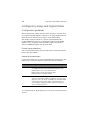
External and internal structure
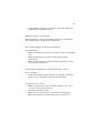
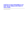
Front panel
No.
Component
1
DVD-ROM or combo drive
2
Volume control
3
Headphone/Earphone port
4
DVD-ROM or combo drive activity indicator
5
DVD-ROM or combo drive Stop/Eject button
6
FDD (Floppy disk drive)
7
FDD activity indicator
8
FDD eject button
9
Security keylock
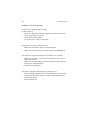
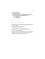
7
No.
Component
10
Hard disk drive (HDD) activity indicator
11
Power indicator
12
Power button
13
USB 2.0 ports
14
5.25-inch drive bays
Front panel LED indicators
Below table lists the LED states on the front panel.
LED
Color
Status
Description
Power
Green
On
Power on
Blinking
System in ACPI sleep mode.
Blinking
HDD activity
Off
No HDD activity
HDD
Green
8
1 System tour
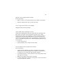
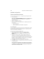
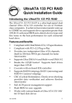
Rear panel
No.
Icon
Component
1
Main power supply unit
2
PS/2 keyboard port
3
PS/2 mouse port
4
Serial port
5
VGA/monitor port
6
Gigabit LAN 1 and 2 ports (10/100/1000 Mbps)
7
USB ports
8
Expansion slot covers
9
Rear system fan
9
LAN LED indicators
The LAN port features two LEDs that indicate the status of each port.
Below table lists the LED states on the LAN ports.
LED
State
Condition
Off
LAN link is not established
On
LAN link is established.
Blinking
Receive or transmit activity is detected.
N/A
Off
10 Mbps data rate is selected.
Yellow
On
100 Mbps data rate is selected.
Green
On
1000 Mbps data rate is selected.
LED
Color
Left
Green
(82573V) /
Yellow
(82541Pl)
Right
Note: The Intel 8257V NIC (Network Interface Controller) has a green indicator and 82541Pl
NIC has a yellow indicator on the top-left corner of their corresponding port.
10
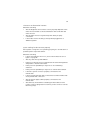
1 System tour
Internal components
No.
Component
1
Power supply unit
2
CPU and HSFD (heat sink-fan duct) assembly
3
Mainboard
4
PCI slot
5
HDD bays
6
5.25-inch device bays
11
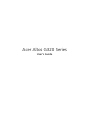
Mainboard layout
The mainboard becomes accessible once you open the system. It should
look like the figure shown below.
No.
Description
1
System fan connector
2
+4V power supply connector
3
CPU fan connector
4
DIMM 1B to 2B sockets
5
DIMM 1A to 2A sockets
12
1 System tour
No.
Description
6
CPU socket
7
+12V power supply connector
8
IDE connector
9
FDD connector
10
SATA port 2 and 3 connectors
11
SCSI status LED connector
12
Maintenance mode jumper
13
Front panel connector
14
SATA port 0 and 1 connectors
15
External USB connector
16
Clear CMOS jumper
17
Chassis intrusion connector
18
PCI slots (32-bit/33 MHz/3.3 V)
19
PCI-Express x4 slot (with x1 throughput)
20
PCI-Express x8 slot (with x4 throughput)
21
PCI-Express x8 slot
22
USB ports
23
Gigabit LAN 1 port (RJ-45)
Gigabit LAN 2 port (RJ-45)
24
VGA/monitor port
25
Serial A port
26
PS/2 keyboard and mouse port
13
Jumper settings
Maintenance mode jumper
The J9H3 jumper is a 2-pin jumper blocks that is used to perform
system maintenance mode options.
The table below lists each jumper option.
Pin no.
Pin function
Description
1-2
Normal boot (default)
Allows normal system operation.
If the jumper block is removed,
the system will attempt to
recover the BIOS by loading the
BIOS code into the flash device
from a disk. This is typically used
when the BIOS becomes
corrupted.
2-3
Config (Maintenance)
Maintenance mode overrides
incorrect BIOS settings
14
1 System tour
Clear CMOS jumper
The 2-pin jumper blocks in the J9G3 jumper are used to perform
clearing of NVRAM and system BIOS recovery options.
The table below lists each jumper option.
Pin no.
Pin function
Description
1-2
Normal boot (default)
Allows normal system operation.
2-3
Clear CMOS (NVRAM)
Clear of NVRAM following POST.
CMOS settings will be cleared in
on the next reset.
2 System setup
This chapter gives you instructions on how to set up
the system. Procedures on how to connect
peripherals are also explained.
17
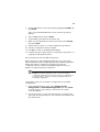
Setting up the system
Pre-installation requirements
Selecting a site
Before unpacking and installing the system, select a suitable site for
the system for maximum efficiency. Consider the following factors
when choosing a site for the system:
•
Near a grounded power outlet
•
Clean and dust-free
•
Stable surface free from vibration
•
Well-ventilated and away from sources of heat
•
Secluded from electromagnetic fields produced by electrical
devices such as air conditioners, radio and TV transmitters, etc.
Checking the package contents
Check the following items from the package:
•
Acer Altos G320 system
•
Acer Altos G320 accessory box
•
System keys
If any of the above items are damaged or missing, contact your dealer
immediately.
Save the boxes and packing materials for future use.
18
2 System setup
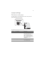
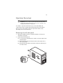
Connecting peripherals
Refer to the illustration below for specific connection instructions on
the peripherals you want to connect to the system.
Note: Consult the operating system manual for information on
how to configure the network setup.
19
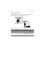
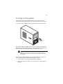
Turning on the system
After making sure that you have properly set up the system and
connected all the required cables, you can now power on the system.
To power on the system, press the power button on the front panel.
The system starts up and displays a welcome message on the monitor.
After that, a series of POST (power-on self-test) messages appears. The
POST messages indicate if the system is running well or not.
Note: If the system does not turn on or boot after pressing the
power button, go to the next section for the possible causes of the
boot failure.
Aside from the POST messages, you can determine if the system is in
good condition by checking if the following occurred:
•
Power indicator on the front panel lights up (green)
•
Num Lock, Caps Lock, and Scroll Lock indicators on the keyboard
light up
20
2 System setup
Power-on problems
If the system does not boot after you have applied power, check the
following factors that might have caused the boot failure.
•
The external power cable may be loosely connected.
Check the power cable connection from the power source to the
power cable socket on the rear panel. Make sure that the cable is
properly connected to the power source and to the power cable
socket.
•
No power comes from the grounded power outlet.
Have an electrician check your power outlet.
•
Loose or improperly connected internal power cables.
Check the internal cable connections. If you are not confident to
perform this step, ask a qualified technician to assist you.
Warning! Make sure all power cords are disconnected from
the electrical outlet before performing this task.
Note: If you have gone through the preceding actions and the
system still fails to boot, ask your dealer or a qualified technician
for assistance.
21
Turning off the system
There are two ways by which you can turn off the server. These include:
To turn off the server, on the Windows taskbar click on the Start
button, point to Shut Down..., select Shut down from the
drop-down window, then click on OK. You can then turn off all
peripherals connected to your server.
If you cannot shut down the server, press and hold the power button
for at least four seconds to force quit all applications and shut down.
Quickly pressing the button may put the server in a Suspend mode
only.
22
2 System setup
3 System upgrade
This chapter discusses the precautionary measures
and installation procedures you need to know
when upgrading the system.
25
Installation precautions
Before you install any server component, we recommend that you read
the following sections. These sections contain important ESD
precautions along with pre-installation and post-installation
instructions.
ESD precautions
Electrostatic discharge (ESD) can damage the processor, disk drives,
expansion boards, mainboard, memory modules and other server
components. Always observe the following precautions before you
install a server component:
1
Do not remove a component from its protective packaging until
you are ready to install it.
2
Wear a wrist grounding strap and attach it to a metal part of the
server before handling components. If a wrist strap is not
available, maintain contact with the server throughout any
procedure requiring ESD protection.
Pre-installation instructions
Perform the steps below before you open the server or before your
remove or replace any component:
1
Turn off the system and all the peripherals connected to it.
2
Unplug all cables from the power outlets.
3
Place the system unit on a flat, stable surface.
4
Open the system according to the instructions on page 27.
5
Follow the ESD precautions described in this section when
handling a server component.
6
Remove any expansion board(s) or peripheral(s) that block access
to the DIMM slots or other component connector.
See the following sections for specific installation instructions on the
component you want to install.
26
3 System upgrade
Warning! Failure to properly turn off the server before you
start installing components may cause serious damage. Do
not attempt the procedures described in the following
sections unless you are a qualified service technician.
Post-installation instructions
Perform the steps below after installing a server component:
1
See to it that all components are installed according to the
described step-by-step instructions.
2
Reinstall any expansion board(s) or peripheral(s) that you have
previously removed.
3
Reinstall the chassis panels.
4
Connect the necessary cables.
5
Turn on the system.
27
Opening the server
Caution! Before you proceed, make sure that you have turned
off the system and all peripherals connected to it. Read the “Preinstallation instructions” on page 25.
You need to open the server before you can install additional
components. The front bezel and left-side panel are removable to
allow access to the system’s internal components. Refer to the
following sections for instructions.
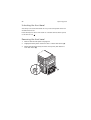
Removing the left-side panel
1
Observe the ESD precautions and pre-installation instructions
described on page 25.
2
Remove the left-side panel.
(1) Loosen the two thumbscrews located on the rear edge of the
left-side panel.
(2) Move the left-side panel release slider all the way down to
unlock the panel.
(3) Slide the left-side panel toward the rear before detaching it
from the chassis.
28
3 System upgrade
Unlocking the front bezel
A security lock secures the bezel door to protect the system unit from
unauthorized access.
Insert the key into the lock and turn it counterclockwise until it points
to the unlock icon
.
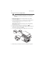
Removing the front bezel
1
Remove the left-side panel. See page 27.
2
Slightly bend the plastic retention tabs to release the latches (1).
3
Gently pull the bezel away from the front panel, then detach it
from the chassis (2).
29
Installing and removing storage devices
The system supports 3.5-inch and 5.25-inch internal storage devices.
The system comes pre-installed with a floppy drive and a DVD or a
combo drive. The empty 5.25-inch half-height bays allow you to install
additional drives such as another DVD drive or a tape drive.
To remove a 5.25-inch storage device:
1
Observe the ESD precautions and pre-installation procedures
described on page 25.
2
Disconnect the IDE power (1) and data (2) cables from the old
drive.
3
Push the lever in the direction of the unlock icon
the drive out of the chassis (4).
4
Observe the post-installation instructions described on page 26.
(3), then pull
30
3 System upgrade
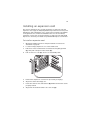
To install a 5.25-inch storage device:
Note: If you are installing a storage device on an empty 5.25-inch
drive bay, you must remove the blank plastic cover on the front
bezel first.
1
Observe the ESD precautions and pre-installation procedures
described on page 25.
2
If you are installing a device on an empty 5.25-inch drive bay, you
must remove the bay cover first. If not, then go to step 3.
To remove the bay cover:
Remove the two screws that secure the cover to the empty bay,
then detach the cover.
3
Push the lever in the direction of the unlock icon
(1).
4
Install a new 5.25-inch drive into the bay (2), then push the lever in
the direction of the lock icon
(3).
5
Connect the IDE data (4) and power (5) cables to the new drive.
6
Observe the post-installation instructions described on page 26.
31
Installing and removing a hard disk
This section include instructions for installing and removing a hard
disk.
The three empty HDD bays allow you to install additional HDDs such as
another SATA or SCSI HDD.
To remove a hard disk:
1
Observe the ESD precautions and pre-installation procedures
described on page 25.
2
Disconnect the power (1) and data (2) cables from the old drive.
3
Push the lever in the direction of the unlock icon
the drive out of the chassis (4).
4
Observe the post-installation instructions described on page 26
(3), then pull
32
3 System upgrade
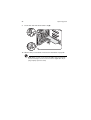
To install a hard disk:
1
Observe the ESD precautions and pre-installation procedures
described on page 25.
2
Push the lever in the direction of the unlock icon
3
Insert the drive into an empty HDD bay (2).
4
Make sure that the drive is properly inserted before closing the
lever, then push the lever in the direction of the lock icon
(3).
5
Connect the data (4) and power (5) cables to the new drive.
6
Observe the post-installation instructions described on page 26.
(1),
33
Upgrading the processor
This section include instructions for installing and removing a processor
and the heat sink-fan duct (HSFD) assembly.
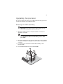
Removing the HSFD assembly
Important: Before removing a CPU from the mainboard, make
sure to create a backup file of all important data.
1
Observe the ESD precautions and pre-installation instructions
described on page 25.
Warning! The heat sink becomes very hot when the system
is on. NEVER touch the heat sink with any metal or with
your hands.
2
Disconnect the CPU fan cable from its mainboard connector. Refer
to “Mainboard layout” on page 11 for the location of the CPU fan
connector.
3
Loosen the four screws that hold the HSFD assembly to the
mainboard (1).
4
Pull the HSFD assembly away from the CPU (2).
34
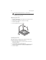
5
3 System upgrade
Place the HSFD assembly upside down on a flat surface.
Note: Wipe off the thermal grease from both the HSFD assembly
and CPU using an alcohol pad.
Removing the CPU
1
Push the socket retainer lever handle down and away from the
socket to release it (1).
2
Pull the lever to a fully open, upright position (2).
3
Lift the load plate (3).
4
Pull out the CPU from the socket (4).
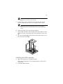
Installing the CPU
The mainboard has a 775-pin processor socket that support Intel
Pentium D, Pentium 4, or Celeron D processors.
1
Observe the ESD precautions and pre-installation instructions
described on page 25.
2
Locate the CPU socket on the mainboard.
3
Push the socket retainer lever handle down and away from the
socket, then pull the lever to a fully open, upright position.
4
Lift the load plate.
35
Note: Do not touch the socket contacts.
5
If a protective cover is installed on the load plate, remove first
before installing the processor. If not, then proceed to step 6.
Note: Do not discard the protective processor cover. Always
replace the processor cover if the processor is removed from the
socket.
6
Remove the CPU from its protective packaging.
7
Align the CPU with the socket, making sure that the CPU’s notched
sides fit into the socket’s pegs, then insert the CPU into the socket
(1).
8
Close the load plate (2), then press the retainer lever down to lock
the load plate in place (3).
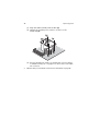
Installing the HSFD assembly
1
Apply thermal grease to the HSFD assembly.
Apply approximately 0.1 ml of the thermal grease compound on
it’s top side.
2
Install the HSFD assembly
36
3 System upgrade
(1) Align the HSFD assembly with the CPU (1).
(2) Tighten the assembly’s four screws to secure it to the
mainboard (2).
(3) Connect the CPU fan cable to its mainboard connector. Refer
to “Mainboard layout” on page 11 for the location of the CPU
fan connector.
3
Observe the post-installation instructions described on page 26.
37
Upgrading the system memory
This section includes instructions for removing and installing a memory
module.
Altos G320 has four DDR2-533/667 DIMM slots. Each slot supports
512 MB, 1 GB or 2 GB memory modules. The maximum memory
capacity is 8 GB.
Memory module installation guidelines
•
The minimum memory configuration is one DIMM, installed in the
DIMM 1A socket (the socket closest to the the CPU sockets).
However, for optimum performance and dual-channel interleave
operation, a minimum of two identical DIMMs should be installed.
DIMMs must be identical (same manufacturer, CAS latency,
number of rows, columns and devices, timing parameters, etc.).
•
DIMMs on channel A (DIMM 1A and 2A) are paired with DIMMs on
channel B (DIMM 1B and 2B) to enable 2-way interleaving. When
only two DIMMs are being used, the population order must be
DIMM 1A and DIMM 1B to ensure dual-channel operating mode.
Refer to the suggested DDR population table below.
DIMM label
Channel
Bank
DIMM 1A
A
1
1
Population order
DIMM 2A
A
1
3
DIMM 1B
B
2
2
DIMM 2B
B
2
4
Note: Refer to “Mainboard layout” on page 11 for the location of
the DIMM sockets for each processor.
Warning! For best performance and dual-channel
interleave operation, DIMM modules must be installed or
removed in matched pairs, following the socket sequence:
DIMM 1A and 1B first, then DIMM 2A and 2B. DIMM
modules of the same type, banking, stacking technology,
and manufacturer must be installed in the Altos G320
system.
38
•
3 System upgrade
Altos G320 mainboard does not support installation of three
DIMMs only.
The table below lists the supported memory installation based on the
memory interleave configuration:
Bank 1
Bank 2
Memory Interleave
DIMM 1A
DIMM 2A
DIMM 1B
DIMM 2B
512 MB
1-way
1 GB
1-way
2 GB
1-way
512 MB
512 MB
2-way
1 GB
1 GB
2-way
2 GB
2 GB
2-way
512 MB
512 MB
512 MB
512 MB
2-way
1 GB
1 GB
1 GB
1 GB
2-way
2 GB
2 GB
2 GB
2 GB
2-way
39
Removing a DIMM
Before you can install a new DIMM in a socket, remove first any
previously installed DIMM from that socket.
Important: Before removing any DIMM from the mainboard,
make sure to create a backup file of all important data.
1
Observe the ESD precautions and pre-installation instructions
described on page 25.
2
Locate the DIMM sockets on the mainboard.
3
Press the holding clips on both sides of the socket outward to
release the DIMM (1).
4
Gently pull the DIMM upward to remove it from the socket (2).
Installing a DIMM
1
Observe the ESD precautions and pre-installation instructions
described on page 25.
2
Locate the DIMM sockets on the mainboard.
Note: For dual-channel interleave operation, a minimum of two
DIMM modules must be installed and following the socket
sequence: DIMM 1A and 1B first, then DIMM 2A and 2B.
40
3 System upgrade
3
Open the clips on the socket.
4
Align then insert the DIMM into the socket (1).
5
Press the holding clips inward to lock the DIMM in place (2).
Note: The DIMM socket is slotted to ensure proper installation.
If you insert a DIMM but it does not fit easily into the socket, you
may have inserted it incorrectly. Reverse the orientation of the
DIMM and insert it again.
6
Observe the post-installation instructions described on page 26.
To reconfigure the system memory:
The system automatically detects the amount of memory installed. Run
the BIOS setup to view the new value for total system memory and
make a note of it.
41
Installing an expansion card
This section explains how to install an expansion card. The onboard
expansion slots supports PCI (Peripheral Component Interconnect) and
PCI Express cards. PCI Express slot is a new type of interface and differs
in length than the conventional PCI/PCI-X slots. You should always
install the correct type of plug-in expansion cards in the x4 and x8 PCI
Express slot. Contact your dealer for qualified PCI Express card vendors.
To install an expansion card:
1
Observe the ESD precautions and pre-installation instructions
described on page 25.
2
Locate an empty expansion slot on the mainboard.
3
Pull the tool-less card bracket lock release latch slightly upward
(1), then pull it away from the chassis (2).
4
Pull out the slot cover (3). Store it for reassembly later.
5
Remove the expansion card from its protective packaging.
6
Align the card in the empty slot.
7
Insert the card into the selected slot (4). Make sure that the card is
properly seated.
8
Align then insert the bracket lock to the slot (5).
42
9
3 System upgrade
Secure the card with the bracket lock (6).
10 Observe the post-installation instructions described on page 26.
Note: When you turn on the system, the BIOS setup automatically
detects and assigns resources to the new device (applicable only to
plug-and-play expansion cards).
4 BIOS setup
This chapter gives information about the
system BIOS and discusses how to configure
the system by changing the settings of the
BIOS parameters.
45
BIOS setup
BIOS setup is a hardware configuration program built into the system's
Basic Input/Output System (BIOS). Since most systems are already
properly configured and optimized, there is no need to run this utility.
You will need to run this utility under the following conditions:
•
When changing the system configuration
•
When a configuration error is detected by the system and you are
prompted ("Run Setup" message) to make changes to the BIOS
setup
Note: If you repeatedly receive Run Setup messages, the battery
may be bad. In this case, the system cannot retain configuration
values in CMOS. Ask a qualified technician for assistance.
•
When redefining the communication ports to prevent any conflicts
•
When making changes to the Power Management configuration
•
When changing the password or making other changes to the
security setup
BIOS setup loads the configuration values in a battery-backed
nonvolatile memory called CMOS RAM. This memory area is not part of
the system RAM which allows configuration data to be retained when
power is turned off.
Before you run BIOS setup, make sure that you have saved all open
files. The system reboots immediately after you close the setup.
46
4 BIOS setup
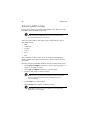
Entering BIOS setup
Power on the server to start the system POST process. During bootup,
press F2 to enter the BIOS setup screen.
Note: You must press F2 while the system is booting. This key
does not work during any other time.
There are several tabs on the setup screen corresponding to the six
major BIOS menus:
•
Main
•
Advanced
•
Security
•
Power
•
Boot
•
Exit
The parameters on the screens shown in this User’s Guide display
default system values. These values may not be the same as those in
the system.
Note the following reminders when moving around the setup screen:
•
Use the Left and Right arrow keys to move to the next page or to
return to the previous screen.
•
Use the Up and Down arrow keys to select an item.
•
Use the + and - keys to select an option.
Note: You can configure a parameter that is enclosed in square
brackets. Grayed-out items have fixed settings and are not
user-configurable.
•
Use the Tab key to select a field.
•
Use the Enter key to display a submenu screen.
Note: When a parameter is preceeded by a >, it means that a
submenu screen is available.
47
•
Press F1 for General Help on using the BIOS setup.
•
Press F10 to save changes and close the BIOS setup.
•
Press Esc to close the BIOS setup.
In the descriptive table following each of the screen illustrations,
settings in boldface are the default and suggested parameter settings.
Note: The BIOS screens shown in the following pages may vary
depending on the system configuration.
48
4 BIOS setup
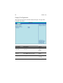
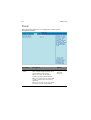
Main
The Main menu displays basic and important information about the
system. These information are necessary for troubleshooting and may
be required when asking for technical support.
The last two parameters on the screen lets you define the sytem’s date
and time settings. The real-time clock keeps the system date and time.
After setting the date and time, you do not need to enter them every
time you turn on the system. As long as the internal battery remains
good and connected, the clock continues to keep the date and time
accurately even when the power is off.
Parameter
Description
BIOS Version
Version of the BIOS setup utility.
Processor Type
Type of processor currently installed in
the server.
Option
49
Parameter
Description
Option
SW Single
Processor Mode
Enables or disables the dual-core
processor support.
It is recommended that you disable this
feature for maximum performance.
Disable
Enable
Processor Speed
The processor speed is the speed at
which a microprocessor executes instructions. Clock speeds are expressed in
megahertz (MHz), with 1 MHz being
equal to 1 million cycles per second. The
faster the clock, the more instructions
the CPU can execute per second.
System Bus Speed
Indicates the system bus speed.
System Memory
Speed
Indicates the system memory speed.
L2 cache RAM
Total amount of second-level cache
memory that comes with the CPU.
Total Memory
Indicates the total amount of onboard
memory.
Memory Mode
Indicates the memory mode.
Memory Channel
A/B slot 0 or 1
Indicates the total amount of memory
available on DIMM 1A, 1B, 2A or 2B
slots.
Additional System
Information
Displays basic information about the
system.
System Date
Sets the date following the weekdaymonth-day-year format. Valid values for
weekday, month, day, and year are:
Weekday: Sun, Mon, Tue, Wed, Thu, Fri,
Sat
Month: Jan, Feb, Mar, Apr, May, Jun, Jul,
Aug, Sep, Oct, Nov, Dec
Day: 1 to 31
Year: 1980 to 2079
50
4 BIOS setup
Parameter
Description
System Time
Sets the time following the hourminute-second format. Valid values for
hour, minute, and second are:
Hour: 00 to 23
Minute: 00 to 59
Second: 00 to 59
Option
51
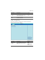
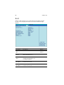
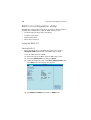
Advanced
The Advanced menu contains parameter values that define how the
system behaves on startup.
Warning! Be cautious in setting parameter values in the
Advanced menu as any incorrect value may cause the
system to malfunction.
Press Enter to enter the submenu screen of the parameters shown in
the screen below.
52
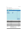
4 BIOS setup
Boot Configuration
The Boot Configuration submenu lets you specify the preferred
settings for system bootup.
Parameter
Description
Option
Num-Lock
Activates the Numeric Lock function upon
booting.
On
CPU Fan Control
Enables or disables the CPU fan control
function.
Enable
Disable
System Fan
Control
Enables or disables the system fan control
function.
Enable
Disable
Lowest Fan
Speed
When set to Slow, the fan will continue to
run at a slow speed when system
temperature is low.
When set to Off, the fan will turn off
when system temperature is low.
Slow
Off
Off
53
Parameter
Description
Option
Max CPUID
Value Limit
This should be enabled in order to boot
legacy operating systems that cannot
support CPUs with extended CPUID
functions.
Disable
Enable
Display Setup
Prompt
When this parameter is enabled, you will
be prompted to press F2 to run BIOS
during boot up.
On
Off
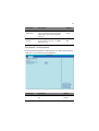
Peripheral Configuration
The Peripheral Configuration submenu lets you define the parameter
settings for the system’s serial and LAN ports.
Parameter
Description
Option
Serial Port
Enables or disables the onboard serial
port.
Enable
Disable
54
4 BIOS setup
Parameter
Description
Option
PCI Express
On-board LAN
Enables or disables the PCI Express
Gigabit Ethernet controller.
Enable
Disable
PCI On-board
LAN
Enables or disables the onboard LAN
device.
Enable
Disable
Drive Configuration
The Drive Configuration submenu lets you define the parameter
settings related to the hard disk/s.
Parameter
Description
Option
Use Automatic
Mode
N/A
Enable
Disable
55
Parameter
Description
Option
ATA/IDE Mode
When set to Enhanced, it will enable all
SATA and PATA controllers.
When set to Legacy, it will enable up to
2 IDE channels for OS that requires
legacy IDE operation.
Enhanced
Legacy
Configure S-ATA
as
Set SATA to IDE or RAID.
IDE
This parameter is disabled when the
ATA/IDE Mode is not set to Enhanced
mode.
RAID
AHCI
S.M.A.R.T.
Enables or disables the S.M.A.R.T. (SelfMonitoring, Analysis and Reporting
Technology) function.
Enable
SATA Port 0, 1, 2
and 3
Displays the SATA HDD connected to
the SATA port.
Primary Master
Specifies the current configuration of
the IDE device connected to the master
port of the primary IDE channel.
Primary Slave
Specifies the current configuration of
the the IDE device connected to the
slave port of the primary IDE channel.
Hard Disk
Pre-Delay (Sec)
Select the time out value for detecting
ATA/ATAPI devices.
Used with older IDE devices with longer
spin up times.
Disable
0
5
15
20
25
30
56
4 BIOS setup
Floppy Configuration
The Floppy Configuration submenu displays the type of floppy drive
installed in the server.
Parameter
Description
Option
Diskette
Controller
Enables or disables the floppy
controller.
Automatic
Diskette Write
Protect
Enables or disables the floppy disk
drive (FDD) write protection.
Disable
Floppy Type
FDD type
1.44 MB
Enable
Disable
Enable
2.88 MB
57
Event Log Configuration
The Event Log Configuration submenu lets you specify the appropriate
settings for system’s event handling function.
The system event log enables you to record and monitor events that
occur in the system (e.g., system temperature changes, fan stops, etc.)
Parameter
Description
View Event Log
Opens the system Event log file for
viewing. This submenu displays the
time and type of event and system
event log file.
Clear Event Logs
Deletes all events in the Event log.
Option
Disable
Enable
Event Logging
Enables or disables the event
logging function of the system.
Enable
Disable
58
4 BIOS setup
Parameter
Description
Option
ECC Event
Logging
Enables or disables the ECC (Error
Correcting Code) event logging
function of the system.
Enable
Disable
Mark Event as
Read
Press Enter to mark all events in
the Event log as read.
Video Configuration
The Video Configuration submenu lets you define the parameter
settings related to the video adapter.
Parameter
Description
Option
Primary Video
Adaptor
Select a parameter for the active
video adapter when the system
boots.
Auto
Ext PCIE Graphics
(PEG)
Ext PCI Graphics
59
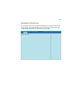
Hardware Monitoring
The Hardware Monitoring submenu displays the current speed status
of the system fans, temperature level of a specified component and
voltage levels and status of the monitored voltage.
60
4 BIOS setup
Chipset Configuration
The Chipset Configuration submenu lets you set the memory interleave
and node interleave settings, specify settings that are related to the
onboard controllers.
Parameter
Description
Memory
Configuration
Offers memory correction and memory
timing adjustments. It also provides
information about the DIMMs installed in
DIMM slots 1A, 1B, 2A, and 2B.
PCI Express
Configuration
Specify settings that are related to the
onboard controllers.
PCI Latency
Timer
Set the latency timer for the PCI bus.
Option
32, 64,
96, 128,
160, 192,
224, 248
61
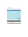
USB Configuration
The USB Configuration submenu lets you specify settings for USB
devices.
Parameter
Description
Option
USB 2.0
Enables the USB 2.0 controller.
Enable
When set to Disable, other USB options
will be grayed out.
Disable
62
4 BIOS setup
Security
The Security menu allows you to safeguard and protect the system
from unauthorized use by setting up access passwords.
Parameter
Description
Option
Supervisor
Password
Prevents unauthorized access to the
BIOS setup utility.
Not Installed
User Password
Secures the system against
unauthorized use. Once you set this
password, you have to type it
whenever you boot the system. User
password is available only when a
Supervisor password is set.
Not Installed
Set Supervisor
Password
Press Enter to change the Supervisor
password.
Set User
Password
Press Enter to change the User
password.
Installed
Installed
63
Parameter
Description
Option
Expansion
Card Text
N/A
Disable
Enable
Chassis
Intrusion
Enables or disables the system to detect
and report chassis intrusion events
Enable
XD
Technology
Enables or disables the execute disable
bit technology function.
Enable
Disable
Disable
Setting the Supervisor/User password:
1
Use the up/down keys to highlight a password parameter
(Supervisor Password or User Password), then press Enter.
A password box will appear.
2
Type a password then press Enter.
The password may consist of up to six alphanumeric characters
(A-Z, a-z, 0-9).
3
Retype the password to verify the first entry, then press Enter
again.
After setting the password, the system automatically sets the
chosen password parameter to Installed.
Removing the User password
1
Use the up/down keys to highlight the Clear User Password
parameter, then press Enter.
2
Enter the current password, then press Enter.
3
Press Enter twice without entering anything in the new and
confirm password fields.
After doing this, the system automatically sets the User password
parameter to Not Installed.
64
4 BIOS setup
Power
The Power menu allows you to configure the system’s power
management feature.
Parameter
Description
Option
After Power
Failure
Defines the power state to resume to
after a system shutdown that is due to
an interruption in AC power.
Stay off
When set to Stay off, the system
remains off after power shutdown.
When set to Last state, the system will
return to active power state prior to
shutdown.
When set to Power on, the system will
be turned on from a power failure.
Last state
Power on
65
Parameter
Description
Option
Wake on LAN
from S5
When set to Power on, the system will
resume from an S5 state if a PME
(Power Management Event) is asserted.
When set to Stay off, the system will not
resume from an S5 state if a PME is
asserted.
Stay off
Power on
66
4 BIOS setup
Boot
The Boot menu allows you to set the drive priority during system
bootup. It also displays information about the installed storage
devices.
Parameter
Description
Option
Boot Menu
Type
N/A
Normal
Boot Device
Priority
Specify the boot search sequence
during the POST process.
Hard Drive
Order
Specify the devices that will be
considered as the primary and
secondary hard drives.
CD-ROM
Drive Order
Displays the type of ATAPI CD-ROM
installed in the system.
Removable
Drive Order
Displays the type of removable devices
installed in the system.
Advance
Varies
67
Parameter
Description
Option
Boot to
Optical
Devices
Enables or disables the system to boot
from an optical device.
Enable
Disable
Boot to
Removable
Devices
Enables or disables the system to boot
from a removable device installed in the
system.
Enable
Disable
Boot to
Network
Enables or disables the system to invoke
the boot ROM of the onboard network
chip.
Enable
USB Boot
Enables or disables the system to boot
from a USB device.
Enable
Disable
ZIP Emulation
Type
Sets the emulation type for USB mass
storage devices.
Floppy
Disable
Hard Disk
68
4 BIOS setup
Exit
The Exit menu displays the various options to quit from the BIOS setup
utility. Highlight any of the exit options then press Enter.
Parameter
Description
Exit Saving
Changes
Saves changes made and close the BIOS setup utility.
The F10 key can also be used for this operation.
Exit Discarding
Changes
Exits system setup without saving any changes.
The Esc key can also be used for this operation.
Load Optimal
Defaults
Loads the default settings for all BIOS setup parameters.
Setup Defaults are quite demanding in terms of
resources consumption. If you are using low-speed
memory modules or other kinds of low-performance
components and you choose to load these settings, the
system might not function properly.
The F9 key can also be used for this operation.
Load Custom
Defaults
Loads the custom settings for all BIOS setup parameters.
69
Parameter
Description
Save Custom
Defaults
Saves the custom settings for all BIOS setup parameters.
Discard
Changes
Discards changes made in the BIOS setup.
The F7 key can also be used for this operation.
70
4 BIOS setup
5 Troubleshooting
This chapter provides possible solutions for specific
problems. If you cannot correct the problem,
contact your local Acer representative or
authorized dealer for assistance.
73
Troubleshooting
This chapter helps you identify and solve problems that might occur
while you are using the system.
For any issue, first ensure that you are using the latest firmware and
files. In addition to the server firmware and files, make sure to update
any drivers used for components you have installed in your system,
such as video drivers, network drivers and SCSI drivers.
If you are unable to resolve your server problems on your own, contact
your dealer or local Acer representative for assistance.
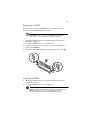
Resetting the system
Before going through in-depth troubleshooting, attempt first to
perform reset the system using one of the methods below.
To do this
Press
Soft boot reset to clear the system memory and reload the
operating system.
Ctrl+Alt+Del
Cold boot reset. Turn the system power off and then on.
This clears system memory, restarts POST, reloads the
operating system and halts power to all peripherals.
Power off/on
Problems following initial system installation
Problems that occur at initial system startup are usually caused by an
incorrect installation or configuration. Hardware failure is a less
frequent cause. If the problem you are experiencing is with a specific
software application, see "There is problem with the application software"
on page 81.
74
5 Troubleshooting
First steps checklist
•
AC power available at the wall outlet?
•
Are the power supplies plugged in? Check the AC cable(s) on the
back of the chassis and at the AC source.
•
Are all cables correctly connected and secured?
•
Is the processor fully seated in the socket on the mainboard?
•
Are all standoffs in the proper location and not touching any
components, causing a potential short?
•
Are all expansion boards fully seated in their slots on the
mainboard?
•
Are all jumper settings on the mainboard correct?
•
Are all jumper and switch settings on expansion boards and
peripheral devices correct? If applicable, ensure that there are no
conflicts - for example, two expansion boards sharing the same
interrupt.
•
Are all peripheral devices installed correctly?
•
If the system has a hard disk drive, is it properly formatted or
configured?
•
Are all device drivers properly installed?
•
Are the configuration settings made in BIOS setup correct?
•
Is the operating system properly loaded? Refer to the operating
system documentation.
•
Did you press the system power button on the front panel to turn
the server on (power indicator should be lit)?
•
Is the system power cord properly connected to the system and
plugged into a NEMA 5-15R outlet for 100-120 V or a NEMA 6-15R
outlet for 200-240 V?
•
Are all integrated components from the tested components lists?
Check the tested memory, and chassis lists, as well as the supported
hardware and operating system list.
75
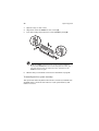
Hardware diagnostic testing
This section provides a more detailed approach to identifying a
hardware problem and locating its source.
Caution! Before disconnecting any peripheral cables from the
system, turn off the system and any external peripheral devices.
Failure to do so can cause permanent damage to the system and/
or the peripheral devices.
1
Turn off the system and all external peripheral devices. Disconnect
each of device from the system, except for the keyboard and the
video monitor.
2
Make sure the system power cord is plugged into a properly
grounded AC outlet.
3
Make sure your video display monitor and keyboard are correctly
connected to the system. Turn on the video monitor. Set its
brightness and contrast controls to at least two thirds of their
maximum ranges (see the documentation supplied with your video
display monitor).
4
If the operating system normally loads from the hard disk drive,
make sure there is no diskette in drive A and no disc in the optical
drive.
5
If the power indicator does light, attempt to boot from a floppy
diskette or from a disc.
6
Turn on the system. If the power indicator does not light, see
“Power indicator does not light” on page 76.
Verifying proper operation of key system lights
As POST determines the system configuration, it tests for the presence
of each mass storage device installed in the system. As each device is
checked, its activity light should turn on briefly. Check if the FDD
activity indicator lights briefly? If not, see “FDD activity indicator does
not light.” on page 76.
Confirming loading of the OS
Once the system boots up, the operating system prompt appears on
the screen. The prompt varies according to the operating system. If the
76
5 Troubleshooting
operating system prompt does not appear, see "No Characters Appear
on Screen" on page 82.
Specific problems and corrective actions
The following contains specific problems that may arise during the use
of your server. Possible solutions are listed for each problem.
Power indicator does not light.
Do the following:
•
Make sure the power button on the front panel is turned on.
•
Make sure the power cable is connected correctly.
•
Make sure that the wall outlet has power. Test it by plugging
another device.
•
Remove all expansion cards and see if the system boots. If
successful, add the cards back in one at a time with a reboot
between each addition.
•
Make sure the memory modules comply with the system
requirements.
•
Make sure the memory modules have been populated according
to the system requirements.
•
Remove the memory modules and reseat them.
•
Make sure the CPU comply with the system requirements.
•
Make sure the CPU is populated according to the system
requirements.
•
Remove and reseat the CPU.
•
Make sure the chassis standoffs are installed only below mounting
holes. Misplaced standoffs may have contact to the pins on the
bottom of the mainboard and cause a short.
FDD activity indicator does not light.
Do the following:
•
Make sure the FDD and signal cables are properly connected.
•
Check that relevant switches and jumpers for the FDD are set
correctly.
77
•
Check that FDD is properly configured.
•
If you are using the onboard diskette controller, use BIOS setup on
page 45 to make sure that onboard “Floppy A” is set to 1.44 MB,
3.5-inch.
HDD activity indicator does not light.
Do the following:
•
Make sure the drive is not disabled in the BIOS setup utility.
•
Make sure the drive’s power and data cables are connected
correctly.
•
Make sure the drive is compatible.
•
Make sure you have not exceeded the power budget for the
server.
•
If using SATA drives, make sure that the master or slave settings
are set correctly. See your drive documentation for details on
setting the master or slave settings.
•
If using SCSI drives, make sure that each SCSI ID number is unique
on the SCSI bus. See your drive documentation for details on
setting the SCSI ID for your drives.
•
If using a RAID configuration with SATA or SCSI drives, make sure
the RAID card is installed correctly.
HDD activity indicator does not light.
If you have installed one or more hard drives in the system, do the
following:
•
Make sure the power and signal cables are connected correctly.
•
If using SATA or SCSI drives, check that relevant switches and
jumpers on the hard drive and backplane board are set correctly.
ODD (Optical disk drive) activity indicator does not light.
Do the following:
•
Make sure the power and signal cables are properly installed.
78
5 Troubleshooting
•
Check that relevant switches and jumpers on the drive are set
correctly.
•
Check that drive is properly configured.
•
Check that onboard IDE controller is enabled in the BIOS setup.
ODD tray cannot be ejected.
•
Insert the tip of a paperclip into the small hole on the ODD drive.
Slowly pull the tray out from the drive until the tray is fully
extended then remove the disc.
ODD drive cannot read a disc.
Do the following:
•
Make sure you are using the correct type of disc.
•
Make sure the disc is properly seated in the drive.
•
Make sure the disc is unscratched.
•
Make sure all cables are connected to the ODD.
Hard drives are not recognized.
•
Make sure the drive is not disabled in the BIOS setup.
•
Make sure the drive is connected correctly and the power cable is
plugged to the power supply.
•
Make sure the drive is compatible.
•
Make sure that you have not exceeded the power budget for the
server.
•
If using SCSI drives, verify that each SCSI ID numbers is unique on
the SCSI bus. Refer to the drive documentation for details on
setting the SCSI ID for your drives.
•
If using IDE drives, verify that the master/slave settings are set
correctly. Refer to the drive documentation for details on setting
the master/slave settings.
79
•
If using RAID configuration with SATA or SCSI drives, make sure
the RAID card is installed correctly.
Bootable CD drive is not detected.
Make sure the Boot settings in the BIOS setup utility is configured to
allow the CD drive to be the first bootable device.
New memory modules installed are not detected.
Do the following:
•
Make sure the memory modules are properly seated on the DIMM
slots.
•
Make sure the memory modules comply with the system
requirements.
•
Make sure the memory modules have been populated according
to the system requirements.
External device connected to a USB connector does not work.
Do the following:
•
Reduce the number of external devices connected to a USB hub.
•
Refer to the documentation that came with the device.
Cannot connect to a server
•
Make sure the network cable is securely attached to the correct
connector at the system rear panel.
•
Try a different network cable.
•
Make sure you are using the correct and the current drivers.
•
Make sure the driver is loaded and the protocls are bound.
80
5 Troubleshooting
Problems with the network
Network status indicator does not light.
Do the following:
•
Check the cabling and network equipment to make sure that all
cables are properly connected.
•
Reinstall the network drivers.
•
Try another port or hub on the switch.
Diagnostics pass but the connection fails.
•
Make sure the network cable is securely attached.
•
Make sure you specify the correct frame type in the NET.CFG file.
The controller stopped working when an adapter was installed.
•
Make sure the cable is connected to the port from the onboard
network controller.
•
Make sure the other adapter supports shared interrupts and your
OS supports shared interrupts.
•
Try reseating the adapter.
The adapter stopped working without apparent cause.
•
Try reseating the adapter first, then try a different slot if necessary.
•
The network files driver may be corrupt or deleted. Delete and
reinstall the drivers.
•
Run the diagnostics.
81
Network activity indicator does not light.
Do the following:
•
Make sure the correct network drivers are loaded on the system.
•
Network might be idle. Try accessing the server.
Server hangs when the drivers are loaded.
Change the PCI interrrupt settings.
System boots when installing a PCI card.
System Server Management feature require full-time standby power.
This means some parts of the system have power going to them
whenever the power cord is plugged in, even if you have turned the
system power off with the power button on the front panel. If you
install a PCI card with the AC power cord plugged in, a signal may be
sent to command the system to boot. Before installing a PCI card, you
should always:
•
Power off the server.
•
Unplug the AC power cord(s) from the server.
There is problem with the application software.
Do the following:
•
Verify that the software is properly configured for the system.
Refer to the software installation and operation documentation
for instructions on setting up and using the software.
•
Try a different version of the software to see if the problem is with
the copy you are using.
•
Make sure all cables are properly connected.
•
If other software runs correctly on the system, contact your vendor
about the defective software.
82
5 Troubleshooting
No characters appear on the screen.
Check the following:
•
Is the keyboard functioning? Test it by turning the “Num Lock”
function on and off to make sure the Num Lock light is
functioning.
•
Is the video monitor plugged in and turned on? If you are using a
switch box, is it switched to the correct system?
•
Are the brightness and contrast controls on the video monitor
properly adjusted?
•
Is the video monitor signal cable properly installed?
•
Does this video monitor work correctly if plugged into a different
system?
•
Is the onboard video controller enabled in the BIOS setup?
•
Remove all expansion cards and see if the system boots. If
successful, add the cards back in one at a time with a reboot
between each addition.
•
Make sure the memory modules comply with the system
requirements.
•
Make sure the memory modules have been populated according
to the system requirements.
•
Remove the memory modules and reseat them.
•
Make sure the CPU comply with the system requirements.
•
Make sure the CPU is populated according to the system
requirements.
If you are using a video controller board, do the following:
1
Verify that the video works using the onboard video controller.
2
Verify that the video controller board is fully seated in the
mainboard connector.
3
Reboot the system for changes to take effect.
4
If there are still no characters on the screen after you reboot the
system and POST emits a beep code, write down the beep code
you hear. This information is useful for your service representative.
5
If you do not receive a beep code and characters do not appear,
the video display monitor or video controller may have failed.
Contact your service representative or authorized dealer for help.
83
Characters are distorted or incorrect.
Check the following:
•
Are the brightness and contrast controls properly adjusted on the
video monitor? Refer to the documentation that came with the
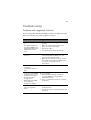
video monitor.
•
Are the video monitor’s signal and power cables properly
connected.
•
Is the video monitor working correctly when plugged into a
different system?
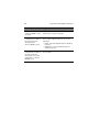
System cooling fan do not rotate properly.
If the system cooling fan is not operating properly, it is an indication of
possible system component failure.
Check the following:
•
Is the power indicator lit? If not, see “Power indicator does not
light.” on page 76 .
•
Are any other front panel LEDs lit?
•
Have any of the fan motors stopped? Use the server management
subsystem to check the fan status.
•
Have your fans speeded up in response to an overheating
situation?
•
Have your fans speeded up in response to a fan that has failed?
•
Is the fan’s power connector properly connected to the
mainboard?
•
Is the front panel board cable connected to both the mainboard’s
front panel board connector?
•
Are the power supply cables properly connected to the
mainboard?
•
Are there any shorted wires caused by pinched cables or have
power connector plugs been forced into power connector sockets
the wrong way?
84
5 Troubleshooting
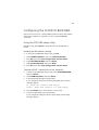
BIOS POST error beep codes
The following table lists the POST error beep codes. Prior to system
video initialization, BIOS uses these beep codes to inform you of error
conditions. The beep code occurs only when a critical error occurs or
when the BIOS fails to boot to the operating system. Not all error
conditions are supported by the BIOS beep codes.
Number of
beeps
Description
1, 2, or 3
Memory error
4 - 7 or
9 - 11
Fatal error indicating a possible serious system problem
8
Video error
Troubleshooting BIOS POST error beep codes
The following table lists the possible beep codes thay may occur while
using the system and is followed by solutions to the situation.
Number of
beeps
1, 2, or 3
Troubleshooting action
• Make sure the memory modules are properly seated on
the DIMM slots.
• Make sure the memory modules comply with the system
requirements.
• Make sure the memory modules have been populated
according to the system requirements.
85
Number of
beeps
4-7, 9-11
Troubleshooting action
• Indicates a fatal error. Consult your dealer or local Acer
representative for assistance.
• If beep codes are generated even when all PCI cards are
absent, consult your system manufacturer’s technical
support.
• Check for a malfunctioning expansion card. If beep codes
are not generated when all expansion cards are absent,
one of the expansion cards is causing the malfunction.
Insert the cards back into the system, booting the system
between each card addition, until the beeps occur again
to reveal the malfunctioning card.
8
• Make sure the video adapter is properly seated on the
expansion slot.
• If the video adapter is an integrated part of the
mainboard, the board may be faulty.
86
5 Troubleshooting
Appendix A: System
management utility
This appendix shows you how to install the ASM
software package and gives information about the
software program and utilities bundled with your
server.
89
Overview
Your Altos G320 server supports the following system management
utilities:
•
ASM (Acer Server Manager)
This utility allows you to spot errors or potential trouble spots in
the network servers through a single management station. For
details go to page 90.
•
RAID configuration utility
The system may be bundled with a utility for changing the RAID
configuration of your SATA or SCSI hard disk. For details go to
page 92.
90
Appendix A: System management utility
ASM
Acer Server Manager is a server management tool. It is specially
designed to help spot errors or potential trouble spots in the network
servers through a single management station. ASM can send a query to
a remote server over the network to request information such as
system hardware and software configuration, system resource usage,
and system performance.
The complete ASM package consists of two major components — the
ASM Agent and the ASM Console. The ASM Agent are the servers to be
managed on the network. The ASM Console is a Windows-based
monitoring station that communicates with the ASM Agents and can
be installed on any agent’s workstation on the network.
System requirements
ASM requires TCP/IP connectivity between the ASM Agent and the
ASM Console.
ASM Agent
•
Intel Pentium 4 (800 MHz), Intel Xeon (800 MHz), AMD Opteron
(1000 MHz) or higher processor
•
512 MB of RAM
•
SATA/SCSI hard drive with at least 100 MB free hard disk space
•
Microsoft Windows 2003 Server/Advanced Server or Red Hat
Enterprise Linux 3.0 operating system
ASM Console
•
Intel Pentium 4 (800 MHz), Intel Xeon (800 MHz), AMD Opteron
(1000 MHz) or higher processor
•
256 MB of RAM
•
SATA/SCSI hard drive with at least 100 MB free hard disk space
•
Microsoft Windows 2003 Professional/XP/Server/Advanced Server
or Red Hat Enterprise Linux 3.0 operating system
91
System setup
Make sure that the system meets the requirements listed before
proceeding. You may also want to change your screen resolution to
800 x 600 or higher for optimum viewing.
Installing ASM Agent
1
Log in to the managed server using the Administrator account.
2
Insert the EasyBUILD Management CD into the server’s ODD. The
installation sequence will automatically be displayed.
3
Select the option for ASM installation. The installation wizard will
be initialized.
4
Follow all onscreen instructions to complete the installation.
For detailed instructions on installing ASM Agent, refer to the
ASM User’s manual.
To launch the program, on the Windows taskbar click on the Start
button, point to Programs, select Acer Server Management Suite
then click ASM Agent.
Installing ASM Console
1
Log in to the target Windows-based PC using the Administrator
account.
2
Insert the EasyBUILD Management CD into the server’s ODD. The
installation sequence will automatically be displayed.
3
Select the option for ASM installation. The installation wizard will
be initialized.
4
Follow all onscreen instructions to complete the installation.
For detailed instructions on installing ASM Console, refer to the
ASM User’s manual.
To launch the program, on the Windows taskbar click on the Start
button, point to Programs, select Acer Server Management Suite
then click ASM Console.
92
Appendix A: System management utility
RAID configuration utility
Caution! Using the RAID configuration utility erases all data
previously saved in the hard drives. Make sure that you backup
important files before starting the configuration process.
SATA RAID configuration utility
The SATA RAID configuration utility allows you to configure and
manage RAID arrays. The configuration utility resides in the BIOS and is
independent of the OS. With the configuration utility, you can:
•
Select a configuration method for physical arrays and logical drives
•
Initialize logical drives
•
Rebuild failed drives
•
Check data consistency
For detailed information on how to use this utility, refer to “Appendix
B: SATA RAID configuration” on page 93.
SCSI RAID configuration utility
The SCSI RAID configuration utility allows you to change the default
RAID configuration, such as the system volume of your SCSI hard disk.
For detailed information on how to use this utility, refer to “Appendix
C: SCSI RAID configuration” on page 113.
Appendix B: SATA
RAID configuration
This appendix provides a description of the
embedded server technology and explains how to
use the utility for configuring and managing RAID
systems.
95
Overview
Embedded with the system BIOS is a configuration utility that provides
server RAID technology and enables you to configure disk arrays and
logical drives. The embedded server RAID technology supports four
SATA ports. These ports support data transfer rates of up to 3.0 Gbps.
Refer to the “Mainboard layout” on page 11 for the location of the
SATA ports.
Features
The embedded server RAID technology include the following features:
BIOS features
•
RAID support before the operating system loads
•
Automatic detection and configuration of disk drives
•
Ability to handle configuration changes
•
Support for Interrupt 13 and Enhanced Disk Drive Specification
•
Support for RAID levels 0, 1, and 10
•
Special handling of error log and rebuilding
•
ROM option size of 64 KB
•
Automatic resume of rebuilding and check consistency
•
Support for BBS (BIOS Boot Specification). If available in the system
BIOS, this allows the user to select the adaptor from which to boot.
(Specification v1.01, January 11, 1996)
•
Co-existence with SCSI and CD devices
•
48-bit LBA support for read, write, and cache flush functions
•
Independent stripe size configuration on each logical drive
•
Ability to select a logical drive as boot device
•
Support for PPM (POST Memory Management) for the BIOS
memory requirement (Specification v1.01, November 21, 1997)
•
Enhanced disk drive support (Specification 2.9, revision 08, March
12, 1998)
•
Industry-standard EBDA
•
S.M.A.R.T. notification at POST
•
Run-time BIOS support for device insertion or removal
96
Appendix B: SATA RAID configuration
•
Independent support for WC, RC, and UDMA (direct memory
access)
•
Support for Stop On Error during bootup
•
Support to disable/enable BIOS state
Driver features
•
Special interface for configuration information, configuration
changes, and manageability
•
Optimized disk access
•
Support for RAID levels 0, 1, and 10
•
Support for Stand-by and Hibernation
Note: The following items require Spy Service to be running in
order to work.
•
Error logging in the operating system event log and on disks
•
Support for online mirror rebuilding
•
Support for check consistency for mirrored disks
•
Bootable RAID 0, 1, and 10
•
Customized messages specific for OEM (original equipment
manufacturer)
•
Soft bad block management
Manageability/Disk console
The features you can use to manage the logical and physical disks in
the system include
•
Configuration information display (in RAID configuration utility
and Hyper configuration utility)
•
Support for RAID levels 0, 1, and 10
•
Online mirror rebuilding (in RAID configuration utility)
•
Online consistency checks (in RAID configuration utility)
•
Array management software
•
Error logging and notification
•
Support for power management features
•
Support for hot device installation and removal
97
•
Automatic resume of rebuilding on restart
•
Support for manual rebuild
•
Physical drive roaming
•
Independent stripe size configuration per logical drive
•
Ability to create up to eight logical drives per array
•
Auto-configuration support of newly added physical drive
•
Support for hot spares
•
Support for disk coercion
•
Array initialization support (fast and normal)
•
Offline data (RAID 1) verification with auto-recovery mechanism
•
Ability to prioritize configurable tasks (for online rebuild, check
consistency, migration, and expansion)
•
Logical drive availability immediately after creation
•
Variable stripe size options from 8 to 128 KB
Configuring arrays
Configure the physical disk drives in arrays. An array can consist of one
to four physical disk drives, depending on the RAID level. A RAID 0
array can consist of one to four physical drives, while a RAID 1 array
consists of two. A RAID 10 array consists of four drives.
Configuration strategies
You have two choices when creating a RAID array.
•
Maximizing fault tolerance
You can maximize fault tolerance to protect against loss of data by
using mirroring. Use mirror configuration (RAID 1) to attain this
objective.
•
Maximizing logical drive performance
You can maximize logical drive performance by using striping.
Select striping configuration (RAID 0) to attain this objective.
RAID 10 combines both striping and mirroring to provide high
data transfer rates and data redundancy.
98
Appendix B: SATA RAID configuration
Assigning RAID levels
Only one RAID level can be assigned to each array. The table below
displays the drives required per RAID level.
RAID Level
Minimum number of
physical drives
Maximum number of
physical drives
0
One
Four
1
Two
Two
10
Four
Four
The factors you need to consider when selecting a RAID level are listed
in the table below:
Level
0
Description
and use
Data divided
in blocks and
distributed
sequentially
(pure striping).
Pros
Cons
No. of
Drives
Fault
Tolerant
High data
throughput
for large
files
• No fault
tolerance.
One to
four
No
100 percent
data
redundancy,
providing
fault
tolerance.
• More disk
space
required.
Two
Yes
• Data is lost if
a drive fails.
Note: Use for
non-critical
data that
requires high
performance.
1
Data
duplicated on
another disk
(mirroring).
Note: Use for
read-intensive,
fault-tolerant
systems.
• Reduces
usable disk
space to the
size of the
smallest
drive.
• Reduced
performance
during
rebuilds.
99
Level
10
Description
and use
A combination
of RAID 1 and
RAID 0. Use
for mediumsized
databases or
any
environment
that requires a
higher degree
of fault
tolerance and
moderate to
medium
capacity.
Pros
Cons
Provides
both high
data
transfer
rates and
complete
data
redundancy.
• More disk
space
required.
• Reduces
usable disk
space to the
size of the
smallest
drive.
• Reduced
performance
during
rebuilds.
No. of
Drives
Fault
Tolerant
Four
Yes
100
Appendix B: SATA RAID configuration
RAID CU (configuration utility)
The RAID CU configures disk arrays and logical drives. The CU resides in
the BIOS and is independent of the OS. With the CU you can:
•
Configure physical arrays and logical drives
•
Initialize logical drives
•
Rebuild failed drives
•
Check data consistency
Using the RAID CU
Starting RAID CU
1
Before attempting to use the RAID CU, make sure to set the
Configure SATA as parameter in the BIOS setup to RAID.
To set the SATA channels as RAID:
(1) During bootup, press F2 to enter the BIOS setup screen.
(2) Select the Advanced menu, then press Enter.
(3) Under the Advanced menu, select Drive Configuration, then
press Enter. The following window appears.
(4) Set Configure S-ATA as parameter to RAID mode.
101
Note: The Configure S-ATA as parameter is disabled when the
ATA/IDE Mode is not set to Enhanced mode.
(5) Save settings and exit the BIOS setup utility.
The system reboots automatically.
2
During bootup, press Ctrl + E to run the RAID configuration utility.
Hold down the Ctrl key while you press E. The Management menu
appears.
Exiting RAID CU
Press Esc when in the utility’s Management menu to exit the utility.
102
Appendix B: SATA RAID configuration
Configuring arrays and logical drives
Configuration guidelines
We recommend using drives with the same capacity in a specific array.
If you use drives with different capacities in an array, the CU treats all
these drives as if they have the capacity of the smallest drive.
The number of physical drives in a specific array determines the
possible RAID levels that you can implement with the array. RAID 0
requires one to four physical drives, RAID 1 requires two physical
drives, and RAID 10 requires four physical drives.
Physical drive parameters
You can change the write policy and read policy in the physical drives,
but not the logical drives.
Logical drive parameters
For the logical drive you can change the RAID level and stripe size. The
table below contains descriptions of the logical drive parameters.
Parameter
Description
RAID level
The number of physical drives in a specific array determines
the RAID levels that can be implemented with the array.
RAID 0 requires one or two physical drives.
RAID 1 requires exactly two physical drives.
RAID 10 requires four physical drives.
Stripe size
The stripe size parameter specifies the size of the segment
written to each disk in a RAID configuration. You can set the
stripe size to 4, 8, 16, 32, 64, or 128 KBs. The default is 64 KB.
A larger stripe size produces higher read performance. If
your computer regularly performs random read requests,
choose a smaller stripe size.
To configure arrays and logical drives you can select from the following
options:
103
•
Quick configuration
•
Detailed configuration
For detailed configuration of arrays and logical drive, you can
choose from the following configuration methods:
•
Easy configuration
•
New configuration
•
View/Add configuration.
Quick configuration
Performing quick configuration
The quick installation steps for configuring arrays and logical drives:
1
Boot the system.
2
Press Ctrl + E to enter the CU screen.
3
Select a configuration method.
4
Create arrays using the available physical drives.
5
Define the logical drive(s) using the space in the arrays.
6
Initialize the new logical drive(s).
Refer to the "Performing detailed configuration" section for detailed
configuration instructions. To ensure best performance, select the
optimal RAID level for the logical drive you create.
104
Appendix B: SATA RAID configuration
Detailed configuration
Performing detailed configuration
Follow the instructions below to configure arrays and logical drives:
1
Start the RAID CU
Make sure the Configure SATA as parameter in the BIOS setup is
set to RAID mode. See “Start the RAID CU” on page 104 for
detailed instructions.
2
Select a configuration method
Choose from the following methods for configuring arrays and
logical drives:
•
Easy configuration
•
New configuration and view/add configuration
Easy configuration
In Easy configuration, the CU associates each hard drive with a single
logical drive. If logical drives have already been configured, the CU
does not change their configuration.
To create arrays using Easy configuration:
1
Under the Management menu, select Configure, Easy
Configuration, then press Enter. The Configuration menu
appears.
2
Use the arrow keys to select a specific drive, then press the
spacebar to associate the selected drive with the current array.
In the menu, the selected drive’s indicator will change from READY
to ONLIN A[array number]-[drive number]. For example,
ONLIN A1-3 means disk drive 3 in array 1.
3
Press Enter after you finish creating the current array.
4
Press F10 to select the configurable arrays, then press the spacebar
to select the array.
The logical drive configuration screen appears. The logical drive
configuration screen displays the logical drive number, RAID level,
logical drive size, number of stripes in the physical array, stripe
size, and state of the logical drive.
105
5
Set the RAID level for the logical drive by highlighting RAID, then
press Enter.
A list of the available RAID levels for the current logical drive
appears.
6
Select a RAID level, then press Enter.
7
Set the RAID logical drive size and stripe size.
8
When you have defined the current logical drive, select Accept,
then press Enter.
9
Repeat step 5 to step 8 to configure additional logical drives.
10 Save the configuration when prompted.
11 Press Esc to return to the Management Menu.
12 Initialize the logical drives. Refer to “Initializing logical drives” on
page 107 for detailed instructions.
New configuration and view/add configuration
New Configuration and View/Add Configuration associate logical
drives with partial and/or multiple physical arrays. New Configuration
deletes the existing configuration and replaces it with the
configuration that you specify. View/Add Configuration lets you
display or modify an existing configuration.
Caution: The New Configuration option erases the existing
configuration data when you save the new array configuration. If
you do not want to delete the existing configuration data, use
View/Add Configuration.
To configure a disk array using New Configuration or View/Add
Configuration:
1
Under the Management menu, select Configure, New
Configuration or View/Add Configuration, then press Enter.
An array selection of the devices connected to the current
controller appears.
2
Use the arrow keys to select the specific drives to include in the
array, then press the spacebar to associate the selected drive with
the current array.
106
Appendix B: SATA RAID configuration
The indicator for the selected drive changes from READY to ONLIN
A[array number]-[drive number]. For example, ONLIN A13 means disk drive 3 in array 1.
3
Press Enter after you finish creating the current array.
4
Press F10 to configure logical drives.
5
Set the RAID level for the logical drive by highlighting RAID, then
press Enter.
A list of the available RAID levels for the current logical drive
appears.
6
Select a RAID level, then press Enter.
7
Set the logical drive size by selecting Size, then press Enter.
By default, the logical drive size associates the available space in
the array(s) with the current logical drive.
8
Set the stripe size.
9
After defining the current logical drive, select Accept, then press
Enter.
10 Save the configuration when the CU prompts you to do so.
11 Initialize the logical drives. Refer to “Initializing logical drives” on
page 107 for detailed instructions.
107
Initializing logical drives
You can initialize the logical drives using batch initialization or
individual initialization. Batch initialization can simultaneously
initialize up to 40 logical drives. While individual initialization can
initialize single logical drives only.
To initialize logical drives using the batch initialization method:
1
Under the Management menu, select Initialize.
2
Use the space bar to select the logical drive.
The logical drive name is highlighted in yellow. To de-select the
logical drive, press the space bar again.
3
Press F10 .
4
Select Yes, then press Enter to begin initialization.
A graph displays the progress of the initialization until it is
completed.
5
After the initialization is completed, press Esc to return to the
previous menu.
When you press Esc while initialization is in progress, the
following options appear:
•
Stop - The CU stores the percentage of the initialization
already completed. When you restart initialization, it
continues from the last percentage completed rather than
from zero percent.
•
Continue - Initialization continues normally.
•
Abort - Initialization is completely aborted. If you restart
initialization, it begins at zero percent.
To initialize logical drives using the individual initialization method:
1
Under the Management menu, select Objects, then Logical
Drive.
2
Select a logical drive, if there is more than one configured, then
press Enter.
3
Select Initialize, then press Enter.
4
Select Yes, then press Enter to begin initialization.
A bar graph displays the initialization progress.
108
5
Appendix B: SATA RAID configuration
After the initialization is completed, press Esc to return to the
previous menu.
When you press Esc while initialization is in progress, the options
— Stop, Continue, and Abort appears. See previous section for
detailed explanation.
109
Rebuilding failed disks
A manual rebuild is used to rebuild failed drives. The CU allows manual
rebuild for an individual drive or a group of drives. The rebuilding of a
group of drives is done through batch mode.
To rebuild a group of failed drives:
1
Under the Management menu, select Rebuild.
A device selection window displays. In the window the failed
drives’ indicators will display FAIL.
2
Use the arrow keys to select the drives to be rebuilt, then press the
spacebar to select the highlighted drives for rebuild.
3
Press F10, then select Yes at the confirmation prompt.
The selected drives’ indicators will change to REBLD.
4
After the rebuild is completed, press Esc to return to the
Management menu.
To rebuild an individual drive:
1
Under the Management menu, select Objects, then Physical
Drive.
2
Use the arrow keys to select a specific drive, then press Enter.
3
Select the Rebuild option from the menu, then respond to the
confirmation prompt.
4
After the rebuild is completed, press any key to display the
previous menu.
Note: If you have auto-rebuild enabled in the BIOS, the rebuild
begins as soon as you enter the RAID CU. If auto-rebuild is
disabled, you have the option to rebuild by following the
procedure in above section.
110
Appendix B: SATA RAID configuration
Checking data consistency
The Check Consistency feature verifies the correctness of the
redundancy data in the selected logical drive and allows the CU to
automatically correct any differences found in the data.
This feature can be used only on a RAID 1 logical drive, to verify the
data consistency between the mirrored physical drives. When a data
inconsistency is found, the CU can either report and fix the
inconsistency or report the inconsisteny only, depending upon the
parameter selected in the Adapter settings.
To start a consistency check:
1
Under the Management menu, select Check Consistency, then
press Enter.
2
Use the space bar to select a logical drive.
Note: A consistency check can only be perfomed in logical drives
that supports RAID level 1. If you select a RAID 0 logical drive, a
check consistency cannot be performed message appears.
To deselect a logical drive, press the space bar again.
3
Press F10.
4
Select Yes to start consistency check, then press Enter.
5
After the consistency check is completed, press Esc to return to the
previous menu.
When you press Esc while the check consistency is in progress, the
following options appear:
•
Stop - The CU stores the percentage of the check consistency
already completed. When you restart the check consistency, it
continues from the last percentage completed rather than
from zero percent.
•
Continue - Check consistency continues normally.
•
Abort - The check consistency is completely aborted. If you
restart check consistency, it begins at zero percent.
111
Troubleshooting
Problems and suggested solutions
The following table describes possible problems you might encounter
while using the CU, along with suggested solutions.
Problem
Suggested solution
Drives are not detected
• Make sure that the cable ends are connected
properly.
or
The system hangs when
the adapter ROM for the
embedded SATA software
RAID scans the SATA
ports.
• Make sure that the power cables to the
drives are connected properly.
• Change the cables.
• If everything fails, change the drive(s).
Operating system does
not boot.
• Check the system BIOS configuration for PCI
interrupt assignments. Make sure some
interrupts are assigned for PCI.
• Make sure that you have properly selected
the Boot Device Priority in the BIOS setup.
See “Boot” on page 66 for more
information.
An error occurs while
reading the
configuration data on a
drive.
The drive has failed and needs to be replaced.
There is no existing RAID
configuration on any of
the drives connected to
the system and the
message “Intel
Embedded Server RAID
Technology Not
Configured” displays.
Do the following:
BIOS reports a mirrored
array is in degraded
mode.
• Make sure all drives are properly connected
and powered on.
1 Run the RAID configuration utility. See
“Start the RAID CU” on page 104 for
detailed instructions.
2 Select a configuration method to configure
the drive(s).
• Reconnect, replace, or rebuild any drive that
has failed.
112
Appendix B: SATA RAID configuration
Problem
Suggested solution
One of the hard drives in
a mirrored (RAID 1) array
has failed.
Replace the failed drive with another drive that
has the same or greater capacity.
A new drive with no
configuration is installed
into the bay which is
already part of a
mirrored (RAID 1) array.
Run the RAID configuration utility to configure
the new drive. Mark the drive as one of the
following:
A new drive with no
configuration is installed
into the bay which is
already part or not part
(is by itself) of a striped
(RAID 0) array.
Run the RAID configuration utility to configure
the new drive.
• Failed - If the AutoRebuild option is disabled
in the CU.
• Rebuilding - If the AutoRebuild option is
enabled in the CU.
Appendix C: SCSI
RAID configuration
This appendix explains how to use the SCSI RAID
configuration utility for creating a RAID volume in
SCSI drives.
115
Configuring the SCSI/SCSI RAID HBA
This section shows how to create a RAID 1 (mirror) volume. This feature
requires the installation or presence of a LSI Logic 53C1030 SCSI
controller.
Using the SCSI HBA setup utility
During bootup, press Ctrl+C to enter the LSI Logic Configuration
screen.
Loading the HBA default settings
1
In the LSI Logic MPT SCSI setup screen, press F2.
2
Select Global Properties, then select Restore Defaults.
3
Press Esc, then select Save changes then exit this menu.
4
Select 53C1020/53C1030, then press Enter.
5
Select Restore Defaults, then press Enter.
6
Press Esc, then select Save changes then exit this menu.
Creating a RAID 1 volume with a hot spare disk
1
In the LSI Logic MPT SCSI setup screen, select 53C1020/53C1030,
then press Enter.
2
Select RAID Properties, then press Enter.
3
In the Array Disk field, press the spacebar.
If you change the settings in the Array Disk field, the following
messages appear:
F3 - Keep Data (Create 2 disk arrays)
Delete - Erase Disk (Create 2 to 6 disk arrays)
4
Press the Delete key to erase all data on the screen.
5
In the Hot Spare field, press the spacebar.
If you change the settings in the Hot Spare field, the following
messages appear:
116
Appendix C: SCSI RAID configuration
WARNING: Data on drive will be LOST!
Press DELETE if data loss OK or any other key to
cancel.
6
Press the Delete key to ignore.
7
Press Esc, then select Save changes then exit this menu.
8
To close the utility and reboot the server, follow the steps below:
(1) Press Esc, then select Exit the Configuration Utility.
The Global properties saved. Hit any key to
reboot message appears.
(2) Press any key to reboot the server.
RAID volume initialization
After you create the RAID volume and saved the changes, the disk
controller will automatically initialize the RAID volume. LSI Logic
53C1030 supports background initialization, there’s no need to wait
for the initialization to complete. Close the LSI Logic Configuration
Utility after saving the changes.
117
Using the MegaRAID configuration utility
Turn on the system. When prompted, press Ctrl+M to enter the
MegaRAID configuration utility. After a few seconds, the Management
menu appears.
Loading the RAID card default setting
1
Under the Management menu, select Objects, then select
Adapter. The current adapter settings appear.
2
Select Factory Default, then Yes to load the default settings.
3
Press Ctrl+Alt+Del to reboot the server.
Creating a RAID 1 volume
1
After rebooting the server, press Ctrl+M to enter the MegaRAID
Configuration screen. The Management menu appears.
2
Select Configuration. The Configuration menu appears.
3
Select New Configuration, then select YES. An array selection
window displays the devices connected to the current controller.
4
Use the arrow keys to select a specific drive, then press the
spacebar to associate the selected drive with the current array.
In the menu, the selected drive’s indicator will change from READY
to ONLINE A[array number]-[drive number].
For example ONLINE A1-2 means disk drive 2 in array 1.
5
Add two drives to the current array, then press Enter.
6
Press F10 to configure the logical drives. The default RAID level for
2 disk drives is RAID 1.
7
Select Accept to use the default setting, then press Enter.
8
Press Enter again to end the array configuration.
9
Select YES to Save Configuration, and press any key to return to
the Configuration menu.
Assigning a hot spare disk
1
Under the Configuration menu, select Add/View Configuration.
2
Use the arrow keys to select a specific drive, then press F4 to set
the drive as a hot spare disk.
118
Appendix C: SCSI RAID configuration
3
Select YES. In the menu, the selected drive’s indicator will change
from READY to HOTSP.
4
Press Esc to end the array configuration.
5
Select YES to Save Configuration, then press any key to return
to the Configuration menu.
Initializing a RAID volume
1
Press Esc to return to the Management menu.
2
Select Initialize. All logical drives will appear under Logical Drives.
3
Using the spacebar, select the drive that you want to initialize. The
selected drive becomes yellow.
4
Press F10, then select YES to start initialization.
5
When initialization is complete, press any key to continue.
6
Press Esc to return to the Management menu.
7
To exit the utility and reboot the server, follow the steps below:
(a) Under the Management menu, press Esc.
(b) Select YES.
(c) Press Ctrl+Alt+Del to reboot the server.
8
Install an Operating System to the RAID array.
119
Index
expansion card
installing
41
41
F
front panel 6
LED indicators
A
Acer Server Manager (ASM) 90
system requirements 90
ASM Agent 90
ASM Console 90
system setup 91
install ASM Agent 91
install ASM Console 91
B
BIOS POST error beep codes 84
BIOS setup 45
Advanced 51
Boot 52
Chipset 60
Drive 54
Event Log 57
Floppy 56
Hardware 59
PCI 61
Peripheral 53
USB 61
Video 58
Boot 66
entering 46
Exit 68
Main 48
Power 64
Security 62
Administrator password 62
removing password 63
User password 62
C
Check data consistency 110
configuring drives 104
easy configuration 104
new configuration 105
view/add configuration 105
CPU 33
installing 34
removing 34
D
DIMM population guidelines
37
E
easy configuration 104
embedded server RAID technology 95
features 95
BIOS 95
driver 96
manageability/disk
console
96
7
H
hard disk 31
installing
removing
HSFD assembly
installing
removing
31
31
33
35
33
I
initialize drive 107
internal components
10
J
jumper settings 13
clear CMOS 14
maintenance mode
13
L
logical drive size
106
M
mainboard 11
MegaRAID configuration utility 117
creating RAID 1 volume 117
initializing RAID volume 117
loading default 117
memory 37
installation guidelines 37
installing 39
reconfiguring 40
N
network port LED indicators
new configuration 105
9
O
opening the system 27
remove front bezel 28
remove left-side panel 27
unlock front bezel 28
P
peripherals 18
power cable 19
R
RAID configuration 113
SATA 92
SCSI 92
RAID configuration utility 100
configure arrays 102
120
configure logical drives 102
consistency check 110
easy configuration 104
initializing drives 107
new configuration 105
option 103
detailed configuration 104
quick configuration 103
rebuilding drives 109
view/add configuration 105
RAID level 102
rear panel 8
rebuild 109
rebuilding drives 109
S
SATA configuration 98
assigning 98
assigning RAID level 98
configuration guidelines 102
RAID configuration utility 100
exit 101
start 100
strategies 97
SATA drive 109
initializing 107
method 107
batch 107
individual 107
logical drive size 106
REBLD indicator 109
rebuilding
group drives 109
individual drive 109
SCSI configuration 115
MegaRAID utility 117
assigning hot spare 117
creating RAID 1 117
initializing RAID volume 118
loading default 117
SCSI HBA utility 115
creating RAID 1 115
initializing RAID volume 116
loading default settings 115
using 115
setting up the system 17
pre-installation requirements 17
size 106
logical drive 106
specification 3
additional media storage 4
chipset 3
graphic interface 4
I/O ports 4
media storage 4
memory subsystem 3
networking 4
OS 5
PCI I/O 4
power supply 5
processor 3
SATA controller 4
SCSI controller 4
storage device 29
install 30
remove 29
stripe size 102
system management utility 90
Acer Server Manager (ASM) 90
RAID configuration utility 92
SATA 92
SCSI 92
system memory 40
reconfiguring 40
system upgrade 23
ESD precautions 25
installation precautions 25
post-installation instructions 26
pre-installation instructions 25
T
troubleshooting 71
confirming loading of the OS 75
hardware diagnostic testing 75
POST error codes 84
problems 76
adapter stopped working 80
cannot connect to a server 79
cannot detect bootable drive
79
cannot detect memory 79
cannot eject DVD/CD tray 78
cannot read DVD/CD 78
controller stopped working
80
DVD/CD drive no light 77
FDD LED no light 76
HDD LED no light 77
HDD not recognized 78
initial system installation 73
LAN LED no light 80
network connection fails 80
no characters on screen 82
power indicator no light 76
RAID
configuration
utility
111
system boot after installing PCI
card 81
system fans do not rotate 83
resetting the system 73
verifying key system lights 75
turning off the system 21
turning on the system 19
power-on problems 20
V
view/add configuration
105