1
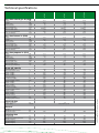
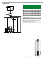
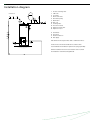
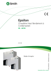
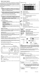
BTI
Light commercial atmospheric
water heater
BTI - 65/85/100
Atmospheric water heater, primarily intended for light commercial /
industrial applications • Control, high limit and energy cut-off
thermostats to ensure safe operation • Safety sensor to prevent flue
spillage • Stainless-steel burner for natural or LP gas • Waterway
access cover for comprehensive waterside tank maintenance
• Replaceable magnesium anode • Fully automatic spark ignition
to minimise standing losses • General fault indicator light
• Optional ancillaries: Unvented kits • Destratification pump kit
• Powered anode • Time clock kit • Flue fan kit • Time clock
kit/7 day timer to minimise standing losses
Innovation has a name.
BTI
BTI 100
BTI 85
BTI 65
Technical specifications
Gas data natural gas 2H (G20)
Input*
Output
Inlet pressure
Burner pressure
Gas consumption**
Diameter pilot orifice
Diameter main orifice
Max. flue gas temperature
Flue gas discharge
kW
kW
mbar
mbar
m3/h
mm
mm
°C
kg/h
18.1
12.7
20
12
1.7
0.56/0.41
3.4
265
27
23.1
16.2
20
11,5
2,2
0.56/0.41
3,9
275
55.2
27.4
19.2
20
10
2.6
0.56/0.41
4.5
275
53.2
kW
kW
mbar
mbar
kg/h
mm
mm
°C
kg/h
17.2
12.3
30
-
1.3
0.23
1.9
265
-
21.8
15.7
30
-
1.6
0.23
2.2
275
81.1
29.6
21.2
30
2.2
0.23
2.5
275
74.8
kW
kW
mbar
mbar
kg/h
mm
mm
°C
16.4
11.7
37
-
1.2
0.23
1.9
265
20.9
15
37
-
1,5
0.23
2.2
275
28.6
20.4
37
2,0
0.23
2.5
275
l
°C
l
l
l
l
l/h
min.
l
l
l
l
l/h
min.
l
l
l
l
l/h
min.
178
80
281
405
529
652
247
43
248
356
465
574
218
49
225
324
423
522
198
54
265
80
396
554
713
871
375
42
348
488
627
767
330
48
317
443
570
697
300
53
355
80
508
713
871
1070
399
53
447
612
777
992
351
61
406
556
706
856
319
67
Gas data butane 3+ (G30)
Input*
Output
Inlet pressure
Burner pressure
Gas consumption**
Diameter pilot orifice
Diameter main orifice
Max. flue gas temperature
Flue gas discharge
Gas data propane 3+ (G31)
Input*
Output
Inlet pressure
Burner pressure
Gas consumption**
Diameter pilot orifice
Diameter main orifice
Max. flue gas temperature
Storage capacity
Max. temperature setting
30 min. ∆T=44°C
60 min. ∆T=44°C
90 min. ∆T=44°C
120 min. ∆T=44°C
Continuous ∆T=44°C
Heating-up time ∆T=44°C
30 min. ∆T=50°C
60 min. ∆T=50°C
90 min. ∆T=50°C
120 min. ∆T=50°C
Continuous ∆T=50°C
Heating-up time ∆T=50°C
30 min. ∆T=55°C
60 min. ∆T=55°C
90 min. ∆T=55°C
120 min. ∆T=55°C
Continuous ∆T=55°C
Heating-up time ∆T=55°C
Electrical data
Power consumption
Power supply
W
VAC/Hz
30
230(-15/+10%) / 50
General
Anodes
-
1
Maximum working pressure
bar
8
Maximum weight
kg
266
382
499
Shipping data
Weight empty
Weight incl. packaging BTT / BTI
Width packaging
Height packaging
Depth packaging
kg
kg
mm
mm
mm
93
105
670
1690
730
122
140
780
1640
870
149
167
780
1830
870
* Gas data on gross value
**Gas consumption at 15°C and 1013.25 mbar
Draw-off capacity
BTI
1
2
3
4
5
Cold water (external)
Hot water (external)
Gas control (internal)
Tank drain valve (internal)
T&P valve (internal)
BTI 85
BTI 100
A
B
D
E
G
K
M
N
R
S
BTI 65
Dimensions
1680
1510
520
655
100
340
1540
1540
295
1330
1585
1450
645
770
130
340
1505
1505
285
1280
1780
1640
675
775
130
340
1685
1685
285
1460
3/4-14
3/4-14
NPT
NPT
1-11.5 NPT 11/4-11.5 NPT
1-11.5 NPT 11/4-11.5 NPT
Rp1/2
3/4-14
3/4-14
NPT
NPT
Dimensions in mm. All BTI water heaters receive a three years
warranty on the tank and one year on parts.
BTI
Installation diagram
Vented
3
4
5
6
9
10
11
14
17
18
19
T&P valve
Stop valve
Non-return valve
Circulation pump
Drain valve
Gas cock
Isolating valve
Hot water outlets
Three way valve
Water tank
Float valve
A
B
C
D
E
H
Cold water
Hot water
Return circulation
Gas supply
Overflow pipe
Expansion vent pipe
A BTI water heater should be installed in accordance with
local standards and ventilation requirements (category
B11BS).
Further installation and connection details can be found
in the Installation & Commissioning Manual.
BTI
Installation diagram
Unvented
1 Pressure reducing valve
3 T&P valve
4 Stop valve
5 Non-return valve
6 Circulation pump
9 Drain valve
10 Gas cock
11 Isolating valve
14 Hot water outlets
15 Expansion relief valve
16 Expansion vessel
A
B
C
D
Cold water
Hot water
Return circulation
Gas supply
A.O. Smith unvented system kits utilise combination valves.
A water heater should be installed in accordance with
local standards and ventilation requirements (category B11BS).
Further installation and connection details can be found in
the Installation & Commissioning Manual.
BTI
Electrical diagram BTI
A
B
C
D
E
F
G
H
K
L
M
N
P
R
S
T
U
V
W
X
Ignition controller
ON/OFF switch
Pilot burner
Spark electrode
Flame probe
Transformer flame detection
(optional)
Combustion products discharge
safety device
Control thermostat
Safety thermostat
Timer (optonal)
Remote button
Terminal block
Terminal block
Earth terminals
Connector to ignition controller
Gas control valve
Connection strip
Tank earth
Casing earth
Control panel base plate earth
Data subject to change INT/0808/BTI/01
Terms and conditions apply, please refer to our website.
For the parts numbers of components
please refer to the “Maintenance and
accessories” chapter.
www.aosmithinternational.com