1
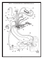
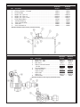
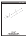
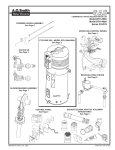
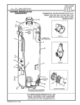
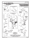
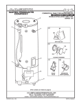
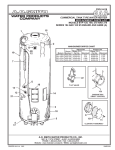
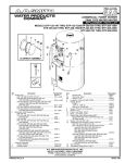
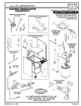
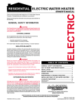
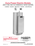
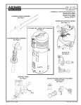
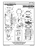
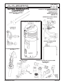
PSD-3-443/c
COMMERCIAL WATER HEATER PARTS LIST
MODEL BTH-300A
SERIES 970/971
MODEL BTH-400A
SERIES 970
POWERED ANODE ASSEMBLY
See Page 8
OPERATING CONTROL WIRING
See Page 4
CYCLONE XHE - MODEL BTH-300A/400A
See Page 2
GAS VALVE
See Page 5
RECIRCULATING SYSTEM
See Page 5
BLOWER/BURNER ASSEMBLY
See Page 7
EXHAUST ELBOW, VENT KIT & BLOWER
INTAKE PARTS
See Page 6
CONTROL PANEL
See Page 3
PRINTED IN U.S.A. 0604
1
195788-001
CYCLONE XHE BTH 300A/400A - PARTS LIST
Item Description
1
2
3
4
5
7
8
9
BTH 300A
970/971
BTH 400A
970/971
Cleanout Gasket .............. 99038 ............ 99038
Cover, Cleanout ............... 99037 ............ 99037
Cover, Left ...................... 194748 .......... 194748
Cover, Right .................... 194749 .......... 194749
Drain Valve ..................... 26273-4 ........ 26273-4
Labels:
800 Help Line ................. 190600 .......... 190600
C.E.C. ............................. 42985 ............ 42985
Cleanout .......................... 78754 ............ 78754
ECO .............................. 192282-1 ...... 192282-1
Electronic Ignition ............ 77860 ............ 77860
Flammable Vapors ......... 193302 .......... 193302
Lighting & Operating ....... 194548 .......... 194548
Relief Valve ..................... 191068 .......... 191068
UL................................... 192870 .......... 192870
Ultra Coat ....................... 193860 .......... 193860
Warning .......................... 193912 .......... 193912
Water Inlet ....................... 94519 ............ 94519
Water Outlet .................... 94518 ............ 94518
Wiring Diagram ............... 194772 .......... 194772
Panel, Back .................... 194750 .......... 194750
Temperature and
Pressure Relief Valve ...... 99383-3 ........ 99383-3
NOTE: Underlined parts are recommended
stock items for emergency replacement.
Consider gas used in your area only.
*Not illustrated.
Standard hardware items may be
purchased locally.
2
CYCLONE XHE BTH 300A/400A - CONTROL PANEL
BTH300A
970/971
BTH400A
970/971
Item
Description
1
2
3
Board, Display Panel ............................ 194808 ............ 194808
Bracket, Mounting Left ......................... 194123-1 ......... 194123-1
Bracket, Mounting Right ........................ 194123 ............ 194123
Control Board, Cable Assembly
(includes 4 & 4A) .................................. 194811 ............ 195018
Control Board ..................................... 194812 ............ 195010
Cable Assembly ................................ 194809 ............ 194809
Junction Box Assembly ........................ 194126 ............ 194126
Junction Box Cover ................................. 2233 ............... 2233
Label, Display Panel ............................. 194203 ............ 194203
Label, Led ............................................. 194915 ............ 194915
Panel Front ........................................... 193884 ............ 193884
Screw, Plastic....................................... 194202 ............ 194202
Switch,Off/On ........................................ 193243 ............ 193243
4
4A
5
6
7
8
9
10
11
CYCLONE XHE BTH 300A/400A - OPERATING CONTROLS & WIRING (See Next Page)
Item
1
2
3
4
5
7
8
9
10
11
11A
12
13
14
15
16
17
18
19
20
21
22
22
23
24
BTH 300A
970/971
Description
BTH 400A
970/971
Cable Assembly, Power Switch ..................................................................194785............ 194785
Blower Prover Air Switch ............................................................................. 194706............ 195013
Box, Anode .................................................................................................194857............ 194857
Box, Junction ..............................................................................................194126............ 194126
Cable Assembly, Low Voltage ....................................................................194918............ 194918
Wire Harness ..............................................................................................194783............ 194783
Cable, Assembly - Controls ........................................................................194784............ 194784
Wire Assembly - Air Flow Switch .............................................................. 192802-2 ......... 192802-2
Wire Assembly - Air Flow Switch ............................................................. 192802-1 ......... 192802-1
Control Board, Cable Assembly (Includes Item 11 & 11A) .......................... 194811............ 195018
Control Board ...........................................................................................194812............ 195010
Cable Assembly ...................................................................................... 194809............ 194809
Display Board .............................................................................................194808............ 194808
Electronic Control .......................................................................................194747............ 194747
Probe, Upper ...............................................................................................196597............ 196597
Probe, Lower ...............................................................................................196598............ 196598
Switch, Blocked Inlet ..................................................................................194911............ 195012
Switch, Blocked Outlet - NAT .....................................................................194910............ 194910
Switch, Blocked Outlet - LP ........................................................................195017............ 195017
Pump, Recirculation ....................................................................................194799............ 194799
Switch, On/Off............................................................................................. 193243............ 193243
Switch, NAT, Low Gas Pressure ............................................................. 191149-6 ......... 191149-6
Switch, LP ,Low Gas Pressure ................................................................. 191149-4 ......... 191149-4
Transformer .................................................................................................192608............ 192608
Valve, Natural Gas .................................................................................... 194536-5 ......... 194536-5
Valve, LP Gas ........................................................................................... 194536-6 ......... 194536-6
Tubing, 1/4" ID, PVC ................................................................................... 193738............ 193738
Cable Assembly, Igniter ..............................................................................194937............ 194937
3
DETAIL 2 - CYCLONE XHE BTH 300A - CONNECTIONS (Continued)
4
RECIRCULATING SYSTEM
Item
1
2
3
4
5
6
7
8
9
10
11
BTH 300A
970/971
Description
BTH 400A
970/971
Elbow, 3/4" Female - 3/4" Female........................................................... 194873 ................. 194873
Elbow, 3/4" Male - 1" Female ................................................................. 194872 ................. 194872
Hose, Flexible ......................................................................................... 194912 ................. 194912
Nipple, 3/4" - Pipe x 2" ........................................................................... 194921-3 .............. 194921-3
Nipple, 3/4" - Pipe x 4" ........................................................................... 194921-2 .............. 194921-2
Nipple, 3/4" - Pipe x close ..................................................................... 194921-1 .............. 194921-1
Pump, Recirculation ................................................................................ 194799 ................. 194799
Tee, Non-Reducing .................................................................................. 194870 ................. 194870
Tube, Closed End Dip ............................................................................. 194924 ................. 194924
Tube, Inlet ............................................................................................... 194820 ................. 194820
Vent, Automatic Air ................................................................................ 194830 ................. 194830
Standard hardware items may be purchased locally.
DETAIL 4 - GAS VALVE
Item
1
2
3
4
5
6
7
8
Description
BTH 300A
970/971
BTH 400A
970/971
Nipple, 3/4" - Pipe ...................................... 85040-18 ........ 85040-18
Nipple, 1/8" - Pipe ...................................... 192948-2 ........ 192948-2
Pipe, Union ................................................... 95515 ............ 95515
Switch, Low Gas Pressure ......................... 191149-6 ........ 191149-6
LP Gas .................................................... 191149-4 ....... 191149-4
Tee, Non-Reducing ........................................ 40119 ............ 40119
Valve, NAT Gas ......................................... 194536-5 ........ 194536-5
Valve, LP Gas ............................................ 194536-6 ........ 194536-6
Orifice, NAT ............................................... 192477-7 ......... 192477
Orifice, LP .................................................. 192477-8 ........ 192477-9
Orifice holder ................................................ 192447 .......... 192447
Standard hardware items may be purchased locally.
5
EXHAUST ELBOW, VENT KIT & BLOWER INTAKE PARTS
Item
BTH 300A
970/971
Description
BTH 400A
970/971
EXHAUST ELBOW AND FITTINGS
1
Adapter, Hose Fitting ....................................................................................................... 192472 .............. 192472
2
Elbow, 90° ....................................................................................................................... 194836 .............. 194836
3
Nipple, Pipe, Closed ........................................................................................................ 194558 .............. 194588
4
Plug, Hex ......................................................................................................................... 194560 .............. 194560
5
Tee ................................................................................................................................... 194559 .............. 194559
6
Tubing ............................................................................................................................ 191746-72 ........ 191746-72
7
Connector, Exhaust ......................................................................................................... 192636 .............. 192636
8
Hose Clamp, 3" ................................................................................................................ 192696 .............. 192696
9
Hose Clamp, 4.5" ............................................................................................................. 192697 .............. 192697
VENT KIT PARTS
10
Elbow w/Screen ............................................................................................................... 192815 .............. 195009
11
Elbow, 45° x 3.5" dia........................................................................................................ 181901 .............. 181901
12
Screen ............................................................................................................................. 181662 .............. 195008
13
Intake Terminal ................................................................................................................ 182167 .............. 182167
14
Wall Plates (2 Req'd) ....................................................................................................... 181557 .............. 181557
15
Silicone Sealer, 2 oz. tube ............................................................................................... 181564 .............. 181564
BLOWER INTAKE PARTS
16
Coupling ........................................................................................................................... 182094 .............. 182094
17
Hose Clamp ..................................................................................................................... 194838 .............. 194838
18
Tube, Intake ..................................................................................................................... 194923 .............. 194923
19
Vent Terminal, Intake ....................................................................................................... 192815 .............. 192815
# Dash number indicates inches.
* Not Illustrated.
192815
195009
6
BLOWER/BURNER - ASSEMBLY
Item
1
2
3
4
5
6
7
8
9
10
11
12
BTH 300A
970/971
Description
BTH 400A
970/971
Burner .................................................................................................. 194779 ................ 194998
Blower/Motor Assembly ....................................................................... 194746 ................ 194746
Flange-Burner ...................................................................................... 194960 ................ 194960
Gasket ................................................................................................. 194817 ................ 194817
Gasket, Burner .................................................................................... 194777 ................ 195016
Gasket-Viewport .................................................................................. 194827 ................ 194827
Ignitor ................................................................................................... 192334 ................ 192334
Screw, #8-18 x 1/2 ............................................................................... 192698 ................ 192698
Screw, Socket Head Cap ..................................................................... 192515 ................ 192515
Screw, Truss Hd. Mach 1/4-20 x 2.00 . ................................................ 194816 ................ 194816
Sensor, Flame ....................................................................................194776-1 ............. 194776-1
Window, Observation ...........................................................................98758-3 .............. 98758-3
Standard hardware items may be purchased locally.
7
POWERED ANODE ASSEMBLY
Item
1
2
3
4
BTH 300A
970/971
Description
BTH 400A
970/971
Anode .........................................................................................................194787 ............ 194787
Anode Wire, 28" ..........................................................................................194925 ............ 194925
Control Box .................................................................................................194857 ............ 194857
LED w. Lead Wire .......................................................................................194959 ............ 194959
A.O. SMITH WATER PRODUCTS COMPANY
5621 W. 115TH STREET • ALSIP, ILLINOIS 60803
PHONE: 1-800-433-2545 • FAX: 1-800-433-2515
Website: www.hotwater.com • E-mail: www.hotwater.com/parts
8