1
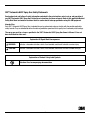
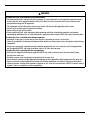
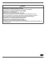
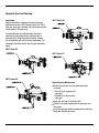
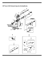
3M™ Automatic HVLP Spray Gun
Owner’s Manual
Series 52
Series 55
Series 56
Series 57
Read Warnings and Instructions
This Manual Covers Spray Gun Models 52, 55, 55ZZ, 56, 56ZZ, 57, 57ZZ and 57UL
Manual Available upon request in Spanish
El manual está disponible en español cuando se lo solicite
3
Table of Contents
Topic Page Number
Safety Statements...................................................................................................................................................2
Contents-Unpacking................................................................................................................................................5
Spray Gun Installation Guidelines.............................................................................................................................8
General Set Up and Spray Gun Use..........................................................................................................................10
Spray Gun Care and Cleaning..................................................................................................................................19
Spray Gun Parts Identification Series 52..................................................................................................................21
Spray Gun Parts Identification Series 55..................................................................................................................23
Spray Gun Parts Identification Series 55ZZ...............................................................................................................25
Spray Gun Parts Identification Series 56..................................................................................................................27
Spray Gun Parts Identification Series 56ZZ...............................................................................................................29
Spray Gun Parts Identification Series 57..................................................................................................................31
Spray Gun Parts Identification Series 57ZZ...............................................................................................................33
Spray Gun Parts Identification Series 57UL..............................................................................................................35
Tip/Nozzle/Air Cap Selection Guide..........................................................................................................................37
Troubleshooting.......................................................................................................................................................39
1
3M™ Automatic HVLP Spray Gun Safety Statements
Read, understand and follow all safety information contained in these instructions prior to set up and operation of
any 3M™ Automatic HVLP Spray Gun. Retain these instructions for future reference. Refer to the applicable Material
Safety Data Sheet and material container label for each material to be sprayed before using this 3M equipment.
Intended Use:
Each 3M™ Automatic HVLP Spray Gun is intended for use by professionals who are familiar with the possible applicable
safety hazards. They are intended to deliver the desired production speed and finish quality for all commonly used coatings.
The spray gun must be set up as specified in the 3M™ Automatic HVLP Spray Gun Owner’s Manual. It has not
been evaluated for other uses.
Explanation Of Signal Word Consequences
WARNING:
Indicates a hazardous situation, which, if not avoided, could result in death or serious injury.
CAUTION:
Indicates a hazardous situation, which, if not avoided, could result in minor or moderate injury.
Explanation of Product Safety Label Symbols
Attention: Read accompanying documentation
3
2
WARNING
To reduce the risks associated with all residual hazards:
•Read, understand, follow and retain for future reference all safety statements in each applicable equipment owner’s
manual and refer to the applicable Material Safety Data Sheet & material container label for each material to be
sprayed before using your 3M equipment.
•This equipment is to be used only by professionals familiar with the possible applicable safety hazards.
•Do not use this product around unsupervised children.
•Never modify any part of this product.
•Always comply with local, state and national codes governing ventilation, fire protection, operation, maintenance,
housekeeping and disposal plus all safety statements in applicable owner manuals, MSDS and material container labels.
To reduce the risks associated with chemical exposure:
•Never point a spray gun at anyone else or place any part of your body in front of a spray nozzle.
•Check spray equipment for damage and proper function before use. Repair/replace worn, damaged or malfunctioning
components.
•Always wear appropriate, approved personal protective equipment for eye, skin, respiratory and hearing protection
per the applicable MSDS and material container labels at all times when spraying.
To reduce the risks associated with fire and explosion:
•Must maintain adequate ventilation per applicable MSDS and material container labels for each material being
sprayed in the work area.
•All ignition sources such as smoking must be kept out of the spray area.
•Always maintain a readily available, approved fire extinguisher or other approved fire fighting equipment in the spray area.
•Never use solvents containing Methylene Chloride and Trichloromethane for any reason to avoid a possible violent,
explosive chemical reaction when exposed to aluminum or zinc (refer to the manufacturer’s MSDS or contact material
supplier if there is any doubt to confirm compatibility).
3
CAUTION
To reduce the risks associated with lifting and handling:
•Always follow proper lifting and handling practices when moving system components.
To reduce the risks associated with tripping, falling and tipping:
•Route air hoses away from traffic areas.
To reduce the risks associated with hazardous air pressure:
•Maintain spray equipment per 3M care and cleaning instructions in the applicable owner’s manual.
•Ensure air input pressure and all applicator system regulators are properly adjusted prior to each use.
•Always follow required air pressure relief procedures for relieving air pressure from the unit.
To reduce the risks associated with compression spring release:
•Maintain a firm grip on fluid adjustment knob when removing.
To reduce the risks associated with environmental contamination:
•Spray materials, solvents, other cleaning materials and electronic components must be disposed of per federal, state
and local regulations.
3
4
Spray Gun Overview
3M spray guns were designed from the inside out for the effective, efficient, economical application of paints, adhesives,
coatings and finishes. These spray guns deliver large spray patterns with very low overspray. The soft, tight, adjustable
pattern with complete atomization results in a high finish quality and absolute control. Each light weight spray gun is
designed for easy handling, reliability and durability and for minimum maintenance costs.
3M’s Automatic HVLP spray guns deliver superior atomization for a wide range of coatings. The standard spray gun
body is made of light weight aluminum. The Zinc HVLP Automatic Spray Gun body is made of composite material.
Manufactured for durability and dependability, both versions are easy to maintain for long-lasting performance.
3M equipment is for professional use only. Hazards can occur from equipment misuse. Any misuse of the equipment
or accessories, such as over pressurizing, modifying parts, using incompatible chemicals and fluids, or using worn or
damaged parts can cause serious bodily injury, fire, explosion or property damage. Please read and follow all Safety
Statements and Instructions.
Contents
Unpacking
Remove the components from the box. Inspect for concealed damage and/or missing items. If you discover any damage
and/or missing pieces, contact your distributor immediately.
Series 52
3M™ Series 52 HVLP Automatic Spray Gun
All Series 52 HVLP Automatic Spray Guns are non-bleed
spray guns with low pressure air inlets and a manual rear fan
control. These spray guns are available with an aluminum
gun body, 10 cfm air consumption, 1:1 reduction ratio, ¾” air
inlet connection, and a 10 psi maximum inlet air pressure*.
These spray guns are most commonly used for stationary or
reciprocator
Series
55 mounting applications.
Series 56
Series 57
* Maximum inlet pressure will yield approximately 10 psi at the air cap.
5
Contents cont.
Series 55
Series 52
Series 57
Series 56
3M™ Series 55 HVLP Automatic Spray Gun
3M™ Series 55ZZ HVLP Automatic Spray Gun (Zinc)
All Series 55 HVLP Automatic Spray Guns are bleeder spray
guns with low pressure air inlets and a manual rear fan
control. These spray guns are available with an aluminum
gun body or a composite gun body with composite
wetted components for zinc compatibility. The technical
specifications include 10 cfm air consumption, 1:1 reduction
ratio, ¾” air inlet connection, and a 10 psi maximum inlet
air pressure*. These guns are most commonly used for
Series 55
stationary or reciprocator mounting applications.
3M™ Series 56 HVLP Automatic Spray Gun
3M™ Series 56ZZ HVLP Automatic Spray Gun (Zinc)
All Series 56 HVLP Automatic Spray Guns are bleeder spray
guns with dual air inlets for separate control of atomization
and fan air pressures. These spray guns are available
with an aluminum gun body or a composite gun body with
Series 57
composite wetted components for zinc compatibility. The
technical specifications include 10 cfm air consumption,
1:1 reduction ratio, ¾” air inlet connection, and a 10
psi maximum inlet air pressure*. These guns are most
commonly used for robotic and remote control applications.
* Maximum inlet pressure will yield approximately 10 psi at the air cap.
3
6
52
56
Contents cont. Series 55
Series 57
3M™ Series 57 HVLP Automatic Spray Gun
All Series 57 HVLP Automatic Spray Guns are bleeder spray
guns with dual air inlets for separate control of atomization
and fan air pressures. These spray guns are available with
an aluminum gun body. The technical specifications include
10 cfm air consumption, 1:1 reduction ratio, ¾” air inlet
connection, and a 10 psi maximum inlet air pressure*.
These guns are most commonly used for robotic and remote
control applications.
3M™ Series 57ZZ HVLP Automatic Spray Gun (Zinc)
All 57ZZ Series HVLP Automatic Spray Guns are bleeder
spray guns with dual air inlets for separate control of
atomization and fan air pressures. These spray guns are
available with a composite gun body with composite
wetted components for zinc compatibility. The technical
specifications include 10 cfm air consumption, 1:1 reduction
ratio, ¾” air inlet connection, and a 10 psi maximum inlet air
pressure*. These guns are most commonly used for robotic
and remote control applications.
3M™ Series 57UL HVLP Automatic Spray Gun (Ultralight)
All 57UL Series HVLP Automatic Spray Guns are bleeder
spray guns with dual air inlets for separate control of
atomization and fan air pressures. These spray guns
are available with a composite gun body. The technical
specifications include 10 cfm air consumption, 1:1 reduction
ratio, ¾” air inlet connection, and a 10 psi maximum inlet air
pressure*. These guns are most commonly used for robotic
and remote control applications.
* Maximum inlet pressure will yield approximately 10 psi at the air cap.
7
Spray Gun Installation Guidelines
3M™ Series 52 HVLP Automatic Spray Gun
3M™ Series 55 HVLP Automatic Spray Gun
3
8
Spray Gun Installation Guidelines cont.
3M™ Series 56 HVLP Automatic Spray Gun
3M™ Series 57 HVLP Automatic Spray Gun
9
General Set Up and Spray Gun Use
For additional instructions refer to your fluid source manual.
3M™ Series 52 HVLP Automatic Spray Gun Connection Diagram
Mounting Hole
Fan Control
Fluid Control
Atomizing Air Inlet
Trigger Air Inlet
Fluid Inlet
Series 52-901
Single Fluid Inlet
Adjustable Fluid
Control
Plug
Series 52-902
Dual Fluid Inlet
Adjustable Fluid
Control
Fluid Inlet
Series 52-904
Dual Fluid Inlet
Non-Adjustable
Fluid Control
Fluid Inlet
3
10
General Set Up and Spray Gun Use cont.
3M™ Series 55 HVLP Automatic Spray Gun Connection Diagram
Atomizing Air Inlet
Mounting Hole
Fan Control
Fluid Control
Trigger Air Inlet
Fluid Inlet
Series 55-901 Series
Single Fluid Inlet
Adjustable Fluid Control
Plug
11
General Set Up and Spray Gun Use cont.
3M™ Series 55ZZ HVLP Automatic Spray Gun Connection Diagram
Atomizing Air Inlet
Mounting Hole
Fan Control
Fluid Control
Trigger Air Inlet
Fluid Inlet
Series 55ZZ-2
Dual Fluid Inlet
Adjustable Fluid
Control
Fluid Inlet
Series 55ZZ-3
Single Fluid Inlet
Non-Adjustable
Fluid Control
Plug
Series 55ZZ-4
Dual Fluid Inlet
Non-Adjustable
Fluid Control
Fluid Inlet
3
12
General Set Up and Spray Gun Use cont.
3M™ Series 56 HVLP Automatic Spray Gun Connection Diagram
Mounting Hole
Atomizing Air Inlet
Fluid Control
Fluid Inlet
Trigger Air Inlet
Fan Control Air Port
Series 56-901
Single Fluid Inlet
Adjustable Fluid
Control
Plug
Fan Control Air Port
Series 56-902
Dual Fluid Inlet
Adjustable Fluid
Control
Fluid Inlet
Fan Control Air Port
Series 56-904
Dual Fluid Inlet
Non-Adjustable
Fluid Control
Fluid Inlet
13
General Set Up and Spray Gun Use cont.
3M™ Series 56ZZ HVLP Automatic Spray Gun Connection Diagram
Mounting Hole
Atomizing Air Inlet
Fluid Control
Fluid Inlet
Trigger Air Inlet
Fan Control Air Port
Series 56ZZ-2
Dual Fluid Inlet
Adjustable Fluid
Control
Fluid Inlet
3
14
General Set Up and Spray Gun Use cont.
3M™ Series 57 HVLP Automatic Spray Gun Connection Diagram
Mounting Hole
Fluid Control
Trigger Air Inlet
Fan Air Control
Fluid Inlet
Series 57-901
Single Fluid Inlet
Adjustable Fluid
Control
Plug
Atomizing Air Inlet
Series 57-902
Dual Fluid Inlet
Adjustable Fluid
Control
Fluid Inlet
Atomizing Air Inlet
Series 57-904
Dual Fluid Inlet
Non-Adjustable
Fluid Control
Fluid Inlet
Atomizing Air Inlet
15
General Set Up and Spray Gun Use cont.
3M™ Series 57ZZ HVLP Automatic Spray Gun Connection Diagram
Mounting Hole
Fluid Control
Trigger Air Inlet
Fluid Inlet
Fan Air Control
Series 57ZZ-1
Single Fluid Inlet
Adjustable
Fluid Control
Plug
Atomizing Air Inlet
Series 57ZZ-2
Dual Fluid Inlet
Adjustable
Fluid Control
Fluid Inlet
Atomizing Air Inlet
Series 57ZZ-3
Single Fluid Inlet
Non-Adjustable
Fluid Control
Fluid Inlet
Atomizing Air Inlet
3
16
General Set Up and Spray Gun Use cont.
3M™ Series 57UL HVLP Automatic Spray Gun Connection Diagram
Mounting Hole
Fluid Control
Trigger Air Inlet
Fluid Inlet
Fan Air Control
57UL-1 Series
Single Fluid Inlet
Adjustable Fluid Control
Plug
Atomizing Air Inlet
57UL-2 Series
Dual Fluid Inlet
Adjustable Fluid Control
Fluid Inlet
Atomizing Air Inlet
57UL-3 Series
Single Fluid Inlet
Non-Adjustable Fluid Control
Plug
Atomizing Air Inlet
57UL-4 Series
Dual Fluid Inlet
Non-Adjustable Fluid Control
Fluid Inlet
Atomizing Air Inlet
17
General Set Up and Spray Gun Use cont.
Adjusting the Fluid Flow
The adjustable fluid control is located at the rear of the
spray gun (if equipped). As a starting point, gently turn
the knob clockwise until you have very little needle
travel. Do not over-tighten. After the needle travel has
stopped, further tightening will only serve to compress
the spring and will not aid in adjustment. Next turn the
knob counterclockwise two full turns. These adjustment
procedures will serve only as a starting point. Fine
tuning of these adjustments will be based on your
material and technique.
Note: The small round pattern can be achieved by
closing down the fan adjustment.
Spray Technique
1.To achieve the best results when spraying material,
keep the spray gun perpendicular to the surface and
maintain a consistent distance of approximately 6 to 8
inches (160-200 mm) from the object being sprayed.
2.Apply coating with 50% overlap to achieve an even
finish.
Note: Your spray gun may be made from aluminum
and may contain aluminum components. Certain
solvents containing Methylene Chloride and
Tricloromethane are not chemically compatible with
aluminum.
Adjusting the Fan Pattern Size
The fan adjustment screw is located at the top of the
Series 52 and Series 55 models, and the fan is adjusted
by remote on the Series 56 and Series 57. As a starting
point, gently turn the knob clockwise until you feel no
further adjustment. Next, turn the knob counter-clockwise
one full rotation. The fan adjustment will allow you to
spray from a small round to a full fan pattern. The pattern
can also be changed from vertical to horizontal by rotating
the air cap a ¼ turn.
Read, understand and follow all safety statements
as well as wear appropriate, approved personal
protective equipment per the applicable MSDS and
material container labels for cleaning solutions.
Vertical Pattern
Horizontal Pattern
3
18
Spray Gun Care and Cleaning
Lubrication:
Regular lubrication is important to maintain the high
performance of your HVLP Automatic Spray Gun. Every
time your spray gun is cleaned, the oil that lubricates the
friction points is washed away.
3M™ Series 56
You must lubricate all working threads after every
cleaning. We recommend using a lubricant such as
petroleum jelly. Using lubricants containing silicone
can contaminate your entire finishing department. The
following illustrations identify the spray gun lubrication
points.
3M™ Series 52
3M™ Series 57
3M™ Series 55
General System Maintenance
Relieve the pressure from the spray gun before
servicing.
1.Turn off the air supply to the
spray gun.
2.Disconnect air line from the
spray gun.
Clean the fluid and air line filters daily.
Check for any fluid leakage from the spray gun and
fluid hoses.
Flush the spray gun before changing colors and when
done operating the spray gun.
19
Spray Gun Care and Cleaning cont.
ATTENTION
8. Clean the front of the spray gun, using a soft-bristle
brush and solvent.
9. Scrub the retaining ring, air cap and fluid nozzle
with a soft-bristle brush. To clean out air cap holes,
use a small brush.
Solvent left in the spray gun air passages could result
in a poor quality paint finish. Do not use any cleaning
method which may allow solvent into the spray gun air
passages. Do not expose air regulators and gauges to
solvent as damage may occur.
Cleaning Process
1. Relieve the pressure from the spray gun before
servicing.
2. Refer to your fluid source manual for removal and
cleaning.
3. To retain unused material or temporarily store mixed
material, see your Local, State, Federal and OSHA
guidelines, along with material manufacturer’s
recommendations for storage.
4. Flush the spray gun. To flush spray gun, run water or
compatible and compliant solvent into the spray gun
fluid passage while triggering the
spray gun.
5. Remove the retaining ring and air cap.
6. Unscrew the fluid needle tip with fingers.
7. Dip the end of a soft-bristle brush into a compatible
solvent. Do not continuously soak the brush’s bristles
with solvent, and do not use a wire brush.
10.Clean the air cap and fluid nozzle after each use. Do not
use metal tools to clean the air cap holes as this may
scratch them; scratches can distort the spray pattern.
Do not soak the retaining ring in solvent for prolonged
periods of time.
11.Thread fluid needle tip on finger tight. Tighten the
nozzle securely to obtain a good seal.
12.Install the retaining ring and air cap.
13.Dampen a soft cloth with solvent and wring-out the
excess. Wipe off the outside of the spray gun.
3
20
3M™ Series 52 HVLP Automatic Spray Gun Parts Identification
2, 2*
21
3M™ Series 52 HVLP Automatic Spray Gun Parts Identification
Item
1
2
2*
3
4
5
6
7
8
9
10
11
12
13
14
15
16
17
18
19
20
21
22
23
24
25
26
27
28
29
30
31
32
33
34
35
36
37
38
39
40
41
42
43
44
45
46
47
48
49
Description
Replacement PN
Retaining Ring
91-043
Air Cap (Composite)
91-009-XXX
Air Cap (Aluminum)
91-071-XXX
Fluid Nozzle
Fluid Fitting
95-025
O-Ring Flat Head Screw
Air Manifold
95-002
Set Screw
UH-612/5
Philips Pan Head Screw
Valve Seal Ball
Snap Ring
Fan Valve Body
95-014
O-Ring
Hex Jam Nut
Valve Stem
95-015
Autogun Body Assembly
95-022
Cylinder Seal (U-Cup)
95-018
O-Ring
Piston 95-005
Needle Tip (Delrin®)
91-107-XXX/4
O-Ring UH-768/5
Needle Shaft
95-010
Piston Return Spring
Needle Return Spring
O-Ring
Cylinder Cap (Adjustable)
Stainless Steel Ball
UH-610
Compression Spring
95-013
Set Screw
UH-691/5
Jam Nut UH-824
Needle Adjustment Screw
95-007
Cylinder Cap (Non-Adjustable)
95-071
Plug
95-077
Packing Nut
Compression Spring
Needle Guide
O-Ring UH-1405/10
O-Ring UH-647/10
Seal Housing
95-017
Teflon® Seal
95-020/2
Seal Nut
95-016
Spacer
95-073
Quick Disconnect Fitting
80-874
Connection – ¼ NPS x 1/8 NPT
80-932
Needle Cover
95-102
Cylinder Cap (Adjustable) Assembly 95-039
Fan Control Assembly
94-041
Fluid Packing Kit
91-200
Universal Maintenance Kit
95-043
(Pack of 5)
(Pack of 4)
(Pack of 5)
(Pack of 5)
(Pack of 10)
(Pack of 10)
(Pack of 2)
Note: For all part numbers with X, see page 37
* Denotes difference in material
3
22
3M™ Series 55 HVLP Automatic Spray Gun Parts Identification
23
3M™ Series 55 HVLP Automatic Spray Gun Parts Identification
IItem
1
2
2*
3
4
5
6
7
8
9
10
11
12
13
14
15
16
17
18
19
20
21
22
23
24
25
26
27
28
29
30
31
32
33
34
35
36
37
38
39
40
41
42
43
44
Description
Retaining Ring
Air Cap (Composite)
Air Cap (Aluminum)
Fluid Nozzle
Fluid Fitting
Autogun Body Assembly
Cylinder Seal (U-Cup)
Piston
O-Ring Needle Tip (Delrin®)
Needle Shaft
Needle Return Spring
Cylinder Cap (Adjustable)
Stainless Steel Ball
Compression Spring
Set Screw
Jam Nut Needle Adjustment Screw
O-Ring
Air Manifold
Set Screw
Flat Head Screw
Air Inlet Fitting
Philips Pan Head Screw
Valve Seal Ball
Snap Ring
Fan Valve Body
O-Ring
Hex Jam Nut
Valve Stem
Plug
O-Ring Needle Guide
Compression Spring
Packing Nut
Seal Nut
Teflon® Seal
Seal Housing
O-Ring Needle Cover
Fluid Inlet Fitting
Cylinder Cap (Adjustable) Assembly
Fan Control Assembly
Fluid Packing Kit
Universal Maintenance Kit
Replacement PN
91-043
91-009-XXX
91-071-XXX
95-025
95-028
95-018
95-031
UH-768/5
91-107-XXX/4
95-033
UH-610
95-013
UH-691/5
UH-824
95-032
95-030
UH-612/5
(Pack of 5)
(Pack of 4)
(Pack of 5)
(Pack of 5)
95-014
95-036
95-077
UH-1405/10
95-020/2
95-017
UH-647/10
95-102
80-932
95-040
95-042
91-200
95-043
(Pack of 10)
(Pack of 2)
(Pack of 10)
Note: For all part numbers with X, see page 37
* Denotes difference in material
3
24
3M™ Series 55ZZ HVLP Automatic Spray Gun Parts Identification
25
3M™ Series 55ZZ HVLP Automatic Spray Gun Parts Identification
Item
1
2
3
4
5
6
7
8
9
10
11
12
13
14
15
16
17
18
19
20
21
22
23
24
26
27
28
29
30
31
32
33
34
35
36
37
38
39
40
41
Description
Retaining Ring
Air Cap (Composite)
Fluid Fitting
Delrin® Fluid Nozzle
Autogun Body Assembly
Cylinder Seal (U-Cup)
Piston
O-Ring Full Delrin® Needle Assembly
Needle Return Spring
Cylinder Cap (Adjustable) Stainless Steel Ball
Compression Spring
Set Screw
Jam Nut Needle Adjustment Screw
Cylinder Cap (Non-Adjustable)
O-Ring
Air Manifold
Set Screw
Flat Head Screw
Air Inlet Fitting
Philips Pan Head Screw
Valve Seal Ball
Fan Valve Body
O-Ring
Hex Jam Nut
Valve Stem
Plug
Fluid Inlet Fitting
Fluid Needle Packing
Packing Nut
Seal Nut
Teflon® Seal
Seal Housing
O-Ring Needle Cover
Cylinder Cap (Adjustable) Assembly
Fan Control Assembly
Universal Maintenance Kit
Replacement PN
91-043
91-009-XXX
95-025
91-148-XXX
95-028
95-018
95-031
UH-768/5
(Pack of 5)
95-048-XXX
95-091
UH-610
95-013
UH-691/5
(Pack of 5)
UH-824
95-032
95-080
95-030
UH-612/5
(Pack of 5)
95-014
95-036
95-077-D
80-932
91-139
91-023-D
95-020/2
95-017
UH-647/10
95-102
95-040
95-042
95-043
(Pack of 2)
(Pack of 10)
Note: For all part numbers with X, see page 37
3
26
3M™ Series 56 HVLP Automatic Spray Gun Parts Identification
27
3M™ Series 56 HVLP Automatic Spray Gun Parts Identification
Item
1
2
2*
3
4
5
6
7
8
9
10
11
12
13
14
15
16
17
18
19
20
21
22
23
24
25
26
27
28
29
30
31
32
33
34
35
36
37
Description
Replacement PN
Retaining Ring
91-043
Air Cap (Composite)
91-009-XXX
Air Cap (Aluminum)
91-071-XXX
Fluid Nozzle
Fluid Fitting
95-025
Autogun Body Assembly
95-029
Fitting
80-932
Quick Disconnect Fitting
95-038
Cylinder Seal (U-Cup)
95-018
Piston
95-031
O-Ring UH-768/5
(Pack of 5)
Needle Tip (Delrin®)
91-107-XXX/4
(Pack of 4)
Needle Shaft
95-033
Mounting Bracket
95-037
Screw
Set Screw
UH-612/5
(Pack of 5)
Needle Return Spring
Cylinder Cap (Adjustable) Jam Nut UH-824
Needle Adjustment Screw
95-032
Stainless Steel Ball
UH-610
Compression Spring
95-013
Set Screw
UH-691/5
(Pack of 5)
Compression Spring
Cylinder Cap (Non-Adjustable)
95-082
Plug
95-077
O-Ring UH-1405/10
(Pack of 10)
Needle Guide
Compression Spring
Packing Nut
Seal Nut
95-016
Teflon® Seal
95-020/2
(Pack of 2)
Seal Housing
95-017
O-Ring UH-647/10
(Pack of 10)
Needle Cover
95-102
Cylinder Cap (Adjustable) Assembly 95-040
Fluid Packing Kit
91-200
Universal Maintenance Kit
95-043
Note: For all part numbers with X, see page 37
* Denotes difference in material
3
28
3M™ Series 56ZZ HVLP Automatic Spray Gun Parts Identification
29
3M™ Series 56ZZ HVLP Automatic Spray Gun Parts Identification
Item
1
2
3
4
5
6
7
8
9
10
11
12
13
14
15
16
17
18
19
20
21
22
23
24
25
26
27
28
29
30
Description
Replacement PN
Retaining Ring
91-043
Air Cap (Composite)
91-009-XXX
Delrin® Fluid Nozzle
91-148-XXX
Fluid Fitting
95-025-D
Autogun Body Assembly
95-029-D
Fitting
80-932
Quick Disconnect Fitting
95-038
Cylinder Seal (U-Cup)
95-018
Piston
95-031
O-Ring UH-768/5
(Pack of 5)
Full Delrin® Needle Assembly
95-048-XXXD
Mounting Bracket
95-037
Screw
Set Screw
UH-612/5
(Pack of 5)
Needle Return Spring
Cylinder Cap (Adjustable)
Jam Nut 95-089
Needle Adjustment Screw
95-032
Stainless Steel Ball
UH-610
Compression Spring
95-013
Set Screw
UH-691/5
(Pack of 5)
Needle Fluid Packing
91-139
Packing Nut
91-023-D
Seal Nut
95-016-D
Teflon® Seal
95-020/2
(Pack of 2)
Seal Housing
95-017
O-Ring UH-647/10
(Pack of 10)
Needle Cover
95-102
Cylinder Cap (Adjustable) Assembly 95-040
Universal Maintenance Kit
95-043
Note: For all part numbers with X, see page 37
3
30
3M™ Series 57 HVLP Automatic Spray Gun Parts Identification
31
3M™ Series 57 HVLP Automatic Spray Gun Parts Identification
Item
1
2
2*
3
4
5
6
7
8
9
10
11
12
13
14
15
16
17
18
19
20
21
22
23
24
25
26
27
28
29
30
31
32
33
34
35
36
37
38
39
40
41
Description
Replacement PN
Retaining Ring
91-043
Air Cap (Composite)
91-009-XXX
Air Cap (Aluminum)
91-071-XXX
Fluid Nozzle
Fluid Fitting-Elbow
95-SP2-10
Threaded Insert
Mounting Bracket
95-037
Screw
Set Screw
UH-612/5
Pack of 5)
Trigger Fitting
95-SP2-8
Autogun Body Assembly
95-SP2-1
Cylinder Seal (U-Cup)
95-018
Piston
95-031
O-Ring UH-768/5
(Pack of 5)
Needle Tip (Delrin®)
91-107-XXX/4
(Pack of 4)
Needle Shaft
95-033
Needle Return Spring
Cylinder Cap (Adjustable)
Jam Nut UH-824
Needle Adjustment Screw
95-032
Stainless Steel Ball
UH-610
Compression Spring
95-013
Set Screw
UH-691/5
(Pack of 5)
Cylinder Cap (Non-Adjustable)
95-082
Plug
95-077
O-Ring UH-1405/10
(Pack of 10)
Needle Guide
Compression Spring
Packing Nut
Seal Nut
95-016
Teflon® Seal
95-020/2
(Pack of 2)
Seal Housing
95-017
O-Ring UH-647/10
(Pack of 10)
Needle Cover
95-102
Mounting Stud
95-076
Manifold Gasket
95-078
Manifold Block
95-075
Elbow
UH-967
Hex Nut with Lock Washer UH-911
Cylinder Cap (Adjustable) Assembly 95-040
Universal Maintenance Kit
95-043
Fluid Packing Kit
91-200
Note: For all part numbers with X, see page 37
* Denotes difference in material
3
32
3M™ Series 57ZZ HVLP Automatic Spray Gun Parts Identification
33
3M™ Series 57ZZ HVLP Automatic Spray Gun Parts Identification
Item
1
2
3
4
5
6
7
8
9
10
11
12
13
14
15
16
17
18
19
20
21
22
23
24
25
26
27
28
29
30
31
32
33
34
35
36
37
Description
Replacement PN
Retaining Ring
91-043
Air Cap (Composite)
91-009-XXX
Delrin® Fluid Nozzle
91-148-XXX
Fluid Fitting-Elbow
Threaded Insert
Mounting Bracket
95-037
Screw
Set Screw
UH-612/5
Autogun Body Assembly
95-083
Trigger Fitting-Elbow
Cylinder Seal (U-Cup)
95-018
Piston
95-031
O-Ring UH-768/5
Full Delrin® Needle Assembly
95-048-XXXD
Needle Return Spring
Cylinder Cap (Adjustable)
Jam Nut 95-089
Needle Adjustment Screw
95-032
Stainless Steel Ball
UH-610
Compression Spring
95-013
Set Screw
UH-691/5
Cylinder Cap (Non-Adjustable)
95-080
Plug
95-077-D
Needle Fluid Packing
91-139
Packing Nut
91-023-D
Seal Nut
95-016-D
Teflon® Seal
95-020/2
Seal Housing
95-017
O-Ring UH-647/10
Needle Cover
95-102
Mounting Stud
95-076
Manifold Gasket
95-078
Manifold Block
95-075
Elbow
UH-967
Hex Nut with Lock Washer UH-911
Cylinder Cap (Adjustable) Assembly 95-040
Universal Maintenance Kit
95-043
(Pack of 5)
(Pack of 5)
(Pack of 5)
(Pack of 2)
(Pack of 10)
Note: For all part numbers with X, see page 37
3
34
3M™ Series 57UL HVLP Automatic Spray Gun Parts Identification
35
3M™ Series 57UL HVLP Automatic Spray Gun Parts Identification
Item
1
2
3
4
5
6
7
8
9
10
11
12
13
14
15
16
17
18
19
20
21
22
23
24
25
26
27
28
29
30
31
32
33
34
35
36
37
38
Description
Replacement PN
Retaining Ring
91-043
Air Cap (Composite)
91-009-XXX
Delrin® Fluid Nozzle
91-148-XXX
Fluid Fitting-Elbow
Threaded Insert
Mounting Bracket
95-037
Screw
Set Screw
UH-612/5
Autogun Body Assembly
95-083
Trigger Fitting-Elbow
Cylinder Seal (U-Cup)
95-018
Piston
95-031
O-Ring UH-768/5
Delrin® Needle Tip
91-107-XXX/4
Stainless Steel Needle Shaft
95-033
Needle Return Spring
Cylinder Cap (Adjustable)
Jam Nut 95-089
Needle Adjustment Screw
95-032
Stainless Steel Ball
UH-610
Compression Spring
95-013
Set Screw
UH-691/5
Cylinder Cap (Non-Adjustable)
95-080
Plug
95-077-D
Needle Fluid Packing
91-139
Packing Nut
91-023-D
Seal Nut
95-016-D
Teflon® Seal
95-020/2
Seal Housing
95-017
O-Ring UH-647/10
Needle Cover
95-102
Mounting Stud
95-076
Manifold Gasket
95-078
Manifold Block
95-075
Elbow
UH-967
Hex Nut with Lock Washer UH-911
Cylinder Cap (Adjustable) Assembly 95-040
Universal Maintenance Kit
95-043
(Pack of 5)
(Pack of 5)
(Pack of 4)
(Pack of 5)
(Pack of 2)
(Pack of 10)
3
36
3M™ Tip/Nozzle/Air Cap Selection Guide
Standard Tip/Nozzle
Size
.021 (0.5mm)
.028 (0.7mm)
.036 (0.9mm) .043 (1.1mm)
.051 (1.3mm)
.061 (1.5mm)
.072 (1.8mm)
.084 (2.0mm)
.110 (3.0mm)
Description
Replacement Tips
Standard Tip/Nozzle Set
Replacement Tips
Standard Tip/Nozzle Set
Replacement Tips
Standard Tip/Nozzle Set
Replacement Tips
Standard Tip/Nozzle Set
Replacement Tips
Standard Tip/Nozzle Set
Replacement Tips
Standard Tip/Nozzle Set
Replacement Tips
Standard Tip/Nozzle Set
Replacement Tips
Standard Tip/Nozzle Set
Replacement Tips
Standard Tip/Nozzle Set
Replacement PN
91-107-021/4 (Pack of 4)
91-143-021DT
91-107-028/4 (Pack of 4)
91-143-028DT
91-107-036/4 (Pack of 4)
91-143-036DT
91-107-043/4 (Pack of 4)
91-143-043DT
91-107-051/4 (Pack of 4)
91-143-051DT
91-107-061/4 (Pack of 4)
91-143-061DT
91-107-072/4 (Pack of 4)
91-143-072DT
91-107-084/4 (Pack of 4)
91-143-084DT
91-107-110/4 (Pack of 4)
91-143-110DT
Air Cap
Air Cap Number
Description
Replacement PN
2
Aluminum Air Cap
91-071-2
3
Aluminum Air Cap
91-071-3
4
Aluminum Air Cap
91-071-4
5
Aluminum Air Cap
91-071-5
6
Aluminum Air Cap
91-071-6
7
Aluminum Air Cap
91-071-7
8
Aluminum Air Cap
91-071-8
Composite Air Cap
91-009-8
9
Aluminum Air Cap
91-071-9
Composite Air Cap
91-009-9
10
Aluminum Air Cap
91-071-10
Composite Air Cap
91-009-10
11
Aluminum Air Cap
91-071-11
Composite Air Cap
91-009-11
12
Composite Air Cap
91-009-12
13
Composite Air Cap
91-009-13
37
3M™ Tip/Nozzle/Air Cap Selection Guide
Size
Description
.021 (0.5mm) Full Delrin® Needle Assembly Delrin® Fluid Nozzle Replacement PN
95-048-021D
91-148-021 .028 (0.7mm) Full Delrin® Needle Assembly Delrin® Fluid Nozzle 95-048-028D
91-148-028 .036(0.9mm) Full Delrin® Needle Assembly Delrin® Fluid Nozzle 95-048-036D
91-148-036
.043 (1.1mm) Full Delrin® Needle Assembly Delrin® Fluid Nozzle 95-048-043D
91-148-043
.051 (1.3mm) Full Delrin® Needle Assembly Delrin® Fluid Nozzle 95-048-051D
91-148-051
.061 (1.5mm) Full Delrin® Needle Assembly Delrin® Fluid Nozzle 95-048-061D
91-148-061
.072 (1.8mm) Full Delrin® Needle Assembly Delrin® Fluid Nozzle 95-048-072D
91-148-072
.084 (2.0mm) Full Delrin® Needle Assembly Delrin® Fluid Nozzle 95-048-084D
91-148-084
3
38
Troubleshooting
Problem
Bad Spray Pattern
Blistering
Fish Eyes
Heavy Middle Pattern
Intermittent Pulsating Spray
Insufficient Fluid Flow, Pressure Feed
Coarse or Lumpy Surface
Mottled Looking Surface
No Paint Flow
Orange Peel
Overspray is Excessive
Pin-Holing, Solvent Pops
Paint Leak
Cause
Remedy
Air cap or nozzle clogged
Bent fluid needle
Moisture on surface
Wrong solvent
Coats not compatible
Insufficient dry time
Surface too cold
Air contamination
Silicone contamination
Too much fluid pressure
Not enough atomizing pressure
Worn or loose packing
Low fluid pressure
Restriction in fluid line Blocked hose
Fluid nozzle too small
Low fluid pressure
Dirt or dust on surface
Material is contaminated
Coating too thin
Coats too wet
Improper spray technique
Clogged fluid nozzle
Loss of fluid pressure
Clogged air passage
Restriction in mat’l hose
Clogged check valve
Paint drying too fast
Gun too far from target
Viscosity too high
Gun too far from target
Too much atomizing air for coating being
sprayed
Trapped solvent
Improper solvent
System contaminated
Wrong needle size
Damaged-worn needle
Loose fluid nozzle
Worn/loose packing nut
Clean with appropriate solvent
Replace fluid needle
Clean surface
Check solvent
Check material compatibility
Longer dry time
Warm surface
Add air filtration
Clean surface with solvent
Reduce fluid pressure
Increase atomizing pressure
Tighten or replace
Add fluid or increase fluid pressure
Use 3/8” fluid hose Flush or replace hose
Use larger needle/nozzle
Increase fluid pressure
Tack wipe before spray
Change or strain
Use less thinner
Use less thinner
Ensure gun is parallel to work
Clean fluid nozzle
Out of paint
Clean with solvent
Flush with solvent
Replace check valve
Use proper solvent
6-8 inches is ideal
Reduce with solvent
6-8 inches is ideal
Needle not closing
Loose fluid fitting
39
Reduce atomizing air
Apply lighter coats
Check coating manufacturer
Clean all parts
Replace
Replace
Tighten or replace
Tighten or replace
Packing too tight. Broken or missing needle
spring. Dried paint on needle.
Tighten or replace
Spray Equipment Warranty and Limited Remedy
3M™ warrants to the original purchaser that, when used in accordance with 3M’s written instructions, 3M spray
equipment will be free of defects in materials and manufacture for one year from the date of purchase. This warranty
does not apply to damage or malfunction caused by normal wear, failure to maintain, or by any abuse, accident,
tampering, alteration, or misuse of the spray equipment.
To make a claim under the warranty, you must first contact the 3M service center at 1-877-MMM-CARS to receive a
return authorization number. Spray equipment must be returned, freight prepaid by the purchaser, to the service location
address given by the 3M service center. Upon validation of the warranty claim, 3M will replace or repair the spray gun,
at 3M’s option, and return it to the purchaser at 3M’s expense, including parts, labor and return shipping charges. If it is
determined that the claim is not covered by the warranty, the purchaser will be given the option to have the spray gun
repaired outside of the warranty. An estimate of parts and labor will be provided by 3M and must be approved by the
purchaser in advance.
Except as written above, 3M MAKES NO OTHER EXPRESS OR IMPLIED WARRANTIES OR CONDITIONS, INCLUDING BUT NOT
LIMITED TO ANY IMPLIED WARRANTY OR CONDITION OF MERCHANTABILITY OR FITNESS FOR A PARTICULAR PURPOSE. The
purchaser is responsible for determining whether the 3M spray equipment is fit for any particular purpose intended.
Limitation of Liability: The remedies set forth above are exclusive. Except where prohibited by law, 3M and any seller of the
spray equipment will not be liable for any loss or damage arising from or related to the use or inability to use this product,
whether direct, indirect, special, incidental or consequential, regardless of the legal theory or basis of liability asserted.
Contact Information
TO PLACE AN ORDER, contact your 3M Sales Representative or Distributor, or call this number:
1-877-MMM-CARS
(1-877-666-2277)
All written and visual data contained in this document reflects the latest
product information available at the time of publication.
3M reserves the right to make changes at any time without notice.
3M Automotive Aftermarket Division
31100 Solon Road, Bldg. B
Solon, OH 44139-3462
www.3M.com
PRINTED IN U.S.A. ©3M 2008. All Rights Reserved.
3M is a trademark of 3M Company.
Teflon® and Delrin® are registered trademarks of E.I. du Pont de Nemours and Company.
Revision A
34-8701-7283-9
3
40
DO NOT PRINT THIS PAGE
Contact: Correen Rosenberger
Creator: deZinnia
Spec # 34-8701-7283-9
Structure: SS-19907
Inks: Black
Date: 9/05/08
All Prints BLACK
This artwork has been created as requested by 3M. 3M is
responsible for the artwork AS APPROVED and assumes full
responsibility for its correctness.