1
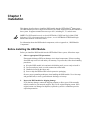
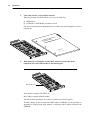
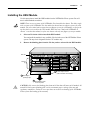
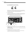
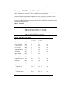
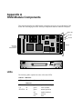
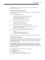
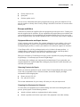
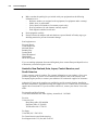
NETBuilder II® HSSI Module
Installation Guide
A member of the NETBuilder® family
THE
PRESIDENT S
ENVIRONMENT
AND
CONSERVATION
CHALLENGE
AWARD
1992
For 3Com User Group Information
1-800-NET-3Com
or your local 3Com office
Manual Part No. 09-0489-000
Published January, 1994. Printed in the U.S.A.
3Com Corporation
5400 Bayfront Plaza
Santa Clara
California
95052-8145
© 3Com Corporation, 1994. All rights reserved. No part of this manual may be reproduced in any form or by any means or used to
make any derivative work (such as translation, transformation, or adaptation) without permission from 3Com Corporation.
3Com Corporation reserves the right to revise this publication and to make changes in content from time to time without obligation
on the part of 3Com Corporation to provide notification of such revision or change.
3Com Corporation provides this manual without warranty of any kind, either implied or expressed, including, but not limited to, the
implied warranties of merchantability and fitness for a particular purpose. 3Com may make improvements or changes in the
product(s) and/or the program(s) described in this manual at any time.
United States Government Legends:
If you are a government agency, then this documentation and the software described herein are provided to you subject to the
following restricted rights:
For units of the Department of Defense:
Restricted Rights Legend: Use, duplication or disclosure by the Government is subject to restrictions as set forth in
subparagraph (c)(1)(ii) of the Rights in Technical Data and Computer Software Clause at 48 C.F.R. 52.227- 7013.
3Com Corporation, 5400 Bayfront Plaza, Santa Clara, California 95052-8145.
For civilian agencies:
Restricted Rights Legends: Use, reproduction or disclosure is subject to restrictions set forth in subparagraph (a)
through (d) of the Commercial Computer Software - Restricted Rights clause 48 C.F.R. 52.227-19 and the limitations
set forth in 3Com’s standard commercial agreement for the software. Unpublished rights reserved under the copyright
laws of the United States.
3ComFacts, Ask 3Com, CardBoard, and CardFacts are service marks of 3Com Corporation.
NETBuilder and NETBuilder II are registered trademarks of 3Com Corporation.
Boundary Routing is a trademark of 3Com Corporation.
CompuServe is a service mark of CompuServe, Inc.
Other trademarks belong to their respective owners.
Manual written by Jennifer Rhoades. Edited by Chris Dresden. Technical illustration by Paul Naas and Deb Knodel. Production by
Ramona Boersma.
ii
Before You Begin
This guide describes how to install, cable, maintain, and troubleshoot the High-Speed Serial
Interface (HSSI) module for the NETBuilder II® base system. The information in this guide
applies to the NETBuilder II 4-slot chassis and the NETBuilder II 8-slot chassis.
For more information about the NETBuilder II base system installation, refer to the
NETBuilder II Base System Installation Guide.
This guide is intended for the system administrator, network equipment installer, or network
manager who is responsible for installing and managing the network hardware. It assumes a
working knowledge of network operations, but it does not assume prior knowledge of 3Com
internetworking equipment.
NOTE: If the information in the release note shipped with your software differs from the
information in this guide, follow the release note.
How to Use This Guide
The following list shows where to find specific information. Refer to the documentation
roadmap in the front of this manual for information on related manuals.
If you are looking for:
Turn to:
Installation procedure
Chapter 1
Troubleshooting and maintenance information
Chapter 2
Description of the HSSI module components
Appendix A
Technical support information
Appendix B
Conventions
“Enter” vs. “Type”
When the word “enter” is used in this manual, it means type
something, then press the Return key. Do not press the
Return key when an instruction simply says “type.”
Text represented as
screen display
This typeface is used to represent displays that
appear on your terminal screen and commands that you
enter, for example:
setd !3 -path cl = e
Bold vs. plain text in
procedures
Bold text summarizes the task you must perform. Plain text
provides additional information, for example:
3.
Assign a name to port 1.
Use a name that is easy to remember.
v
Keys
When specific keys are referred to in the text, they are
called out by their labels, such as “the Return key” or “the
Escape key,” or they may be shown as [Return] or [Esc].
If two or more keys are to be pressed simultaneously, the
keys are linked with a plus sign (+), for example:
Press [Ctrl]+[Alt]+[Del].
Italics
Italics are used to denote new terms or emphasis.
Special Messages
A special format indicates notes, cautions, and warnings. These messages are defined as
follows.
NOTE: Notes call attention to important features or instructions.
CAUTION: Cautions contain directions that you must follow to avoid immediate system
damage or loss of data.
WARNING: Warnings contain directions that you must follow for your personal safety. Follow
all instructions carefully.
vi
Chapter 1
Installation
This chapter describes how to install the HSSI module into the NETBuilder II ® base system.
The HSSI module provides a single serial interface for a WAN connection in the NETBuilder II
base system. It supports transmission rates up to OC1, including E3, T3, and sub-rates.
NOTE: The HSSI module must be used with NETBuilder II HSSI and Single-Mode FDDI
Software 6.2. For information about the software, see the NETBuilder II HSSI and SingleMode FDDI Software 6.2 Release Notes.
For information about the HSSI module components, refer to Appendix A, “HSSI Module
Components.”
Before Installing the HSSI Module
Before you install the HSSI module into the NETBuilder II base system, follow these steps:
1.
Observe appropriate ESD precautions.
Electrostatic discharge (ESD) can damage circuit board components. Failures resulting
from ESD may not be covered under your warranty. To prevent this, follow these handling
procedures:
■
■
■
■
Keep the HSSI module in its antistatic shielded bag until you are ready to install it.
Do not touch pins, leads, or solder connections on the board.
Handle the board by the edges only.
Store or ship the HSSI module in static-protective packaging.
Observe proper grounding techniques when handling the HSSI module: Use a foot strap
and grounded mat, or wear a grounded static discharge wrist strap.
2.
Inspect the HSSI module for shipping damage.
If you find any damage, contact the shipping company to file a report. If the assembly
must be returned to your network supplier, ship it in its original shipping carton. If the
original carton was damaged in shipment, repack the system in a carton that provides
equivalent protection.
1-2
Installation
Before Installing the HSSI Module
3.
Verify that you have received all the contents.
When you purchase the HSSI module, you receive the following:
■
■
HSSI module
NETBuilder II HSSI Module Installation Guide
If an item is missing from an undamaged carton, contact your network supplier to secure a
replacement.
ule
I Mod
®I HSS
I
e
r
uildetion Guid
mily
NETB
der fa
lla
TBuil
Insta
e NE
mber
A me
of th
ation
Inform
roup
e
ser G
om U -3Com om offic
.S.A.
l 3C
NET
For 3C
the U
0
1-800-your loca
489-00Printed in
-0
or
No. 09 1994.
l Part nuary,
Manuablished Ja
Pu
4.
Write down the serial number and the MAC address from the label on the
component side of the HSSI module on the following line:
Serial number label
Serial number example: S/N:1BK12345
MAC address example: 0800021A4B5C
You will need this information if you have to contact your network supplier.
The MAC address is also encoded in the HSSI module’s EEPROM. Use the procedure in
Appendix B, “Displaying the MAC Address,” to display the MAC address encoded in the
EEPROM.
Installation
1-3
Installing the HSSI Module
Installing the HSSI Module
Use this procedure to install the HSSI module into the NETBuilder II base system. You will
need a small flathead screwdriver.
NOTE: There are two versions of the NETBuilder II 4-slot and 8-slot chassis. The older, singlewide versions of the NETBuilder II 4-slot and 8-slot chassis have two flipper ejectors for each
module. The newer, dual-wide versions have one flipper ejector for each module, except for the
top slot which is reserved for the CEC module. When the term “dual-wide NETBuilder II
chassis” is used in this manual, it refers to a chassis with only one flipper ejector per module.
1.
Select an I/O slot in which to install the HSSI module.
You can install the module in any available I/O slot in the rear of the NETBuilder II base
system. The top slot is designated for the CEC module only.
2.
Remove the blanking plate from the I/O slot you have selected for the HSSI module.
CEC slot
I/O slots
(8)
1
8
2
7
3
6
4
5
1
2
Loosen captive screws
(with screwdriver if necessary)
Push flipper
ejector(s) open
3
Slide blanking plate
out of rear panel
CAUTION: Only remove the blanking plate from an I/O slot that will house an I/O module. All
unused I/O slots require blanking plate covers to maintain proper cooling of the unit and
regulatory compliance. Failure to cover open slots can result in overheating of the NETBuilder
II base system and voiding of the warranty.
1-4
Installation
Installing the HSSI Module
3.
Insert the HSSI module into an uncovered I/O slot.
Make sure the flipper ejector(s) are in an open position.
Flipper
open
Flipper
closed
With the connector end toward the backplane and the board facing up (check that the
labels on the connector/LED panel are right side up), grasp the left and right sides of the
panel and fit the board into the I/O slot opening along the guide rails.
4.
Lock the board in the slot.
For the dual-wide NETBuilder II chassis, use your thumbs to push the board all the way
into the slot. As you slide the board into the slot, the flipper ejector engages itself. For
single-wide NETBuilder II chassis, push the flipper ejector closed.
1
8
2
7
3
6
4
5
®
STATUS
Push board into slot
5.
Check that the connector/LED panel of the newly inserted module is flush with the
NETBuilder II chassis.
To verify that the board is seated correctly, check that it is aligned with the connector/LED
panel of an installed module.
6.
Hand tighten the captive screws. Do not use a screwdriver.
A solid connection of the connector/LED panel to the chassis is required for proper
operation. Do not use the screws to force the board into place.
Installation
1-5
Installing the HSSI Module
Cabling the HSSI Module for Network Connection
A SCSI-type cable connects the HSSI Module DTE connector to a Data Service Unit (DSU).
Table 1-1 describes the connectors. Table 1-2 describes the pin assignments.
3Com recommends using minimum lengths of this cable, especially if you plan to use these
serial lines at high speeds. The maximum cable length allowed is 50 feet.
To connect the HSSI module to the network, insert a SCSI type cable into the female connector
in the rear of the HSSI module
Table 1-1. Connectors
Connector
Description
Plug connector type
2 row, 50 pin, shielded tab connectors,
AMP plug part number 749111-4 or equivalent
AMP shell part number 749193-2 or equivalent
Receptacle type
2 row, 50 pin, receptacle header with rails and latch blocks,
AMP part number 749075-5 or equivalent
Table 1-2. HSSI Adapter Cable Pinouts
Signal Name
Mnemonic
Pin Number
(+ side)
Pin Number
(- side)
Direction
Signal Ground
SG
1
26
--
Receive Timing
RT
2
27
in
DCE Available
CA
3
28
in
Receive Data
RD
4
29
in
Loopback Request
LC
5
30
in
Send Timing
ST
6
31
in
Signal Ground
SG
7
32
--
DTE Available
TA
8
33
out
Terminal Timing
TT
9
34
out
Loopback Circuit A
LA
10
35
out
Send Data
SD
11
36
out
Loopback Circuit B
LB
12
37
out
Signal Ground
SG
13
38
--
14 - 18
39 - 43
out
19
44
--
20 -24
45 - 49
in
25
50
--
5 ancillary to
DCE
Signal Ground
SG
5 ancillary from
DCE
Signal Ground
SG
1-6
Installation
Installing the HSSI Module
CAUTION: Connections between 3Com equipment and other equipment and peripherals must
be made using shielded cables in order to maintain compliance with FCC, and other agency
radio frequency emissions limits. All interconnection cables should be equipped with shielded
connectors. The backshells of these connectors must completely surround the cable shield.
Internal Loopback test
An internal loopback test is performed automatically when you insert the HSSI module into the
NETBuilder II chassis. A successful loopback test is indicated by the following example
message:
3Com Corporation NETBuilder II power-on
IPL1: 1.0.5, REM: 1.0.5
Booting from floppy...
Decompressing...
Booting complete
HSSI Interface: Self
PHY_CONTROLLER: Self
MAC CONTROLLER: Self
FDDI Started. MAC[4]
Tests passed - slot 1
Tests passed - slot 3
Tests passed - slot 4
PHY[3]
Wed Dec 31 16:00:06 1969 Path 4 AVAILABLE
Wed Dec 31 16:00:06 1969 Path 1 AVAILABLE
Wed Dec 31 16:00:06 1969 Path 2 AVAILABLE
Wed Dec 31 16:00:06 1969 Path 2 UP
Fri Sep 10 16:50:06 1993 System Initialized and Running
Fri Sep 10 16:50:06 1993 Path 4 UP
Fri Sep 10 16:50:17 1993 Path 1 UP
Fri Sep 10 16:50:35 1993 Port 2 - Forwarding State
Fri Sep 10 16:50:36 1993 Port 4 - Forwarding State
Fri Sep 10 16:50:56 1993 Port 1 - Forwarding State
If you receive a different message, refer to Chapter 2, “Troubleshooting and Maintenance,” for
the appropriate action to take.
Hotswap
When you hotswap an HSSI module in a running system, the following is displayed:
HSSI Interface: Self Tests passed - slot 1
Wed Dec 31 16:00:06 1969 Path 1 AVAILABLE
Fri Sep 10 16:50:17 1993 Path 1 UP
Chapter 2
Troubleshooting and Maintenance
This chapter describes how to troubleshoot and maintain the HSSI module.
If you are unable to resolve a problem with your HSSI module, you will need to contact a
customer service representative. Refer to Appendix C, “Technical Support,” for information
about who to contact in your area.
Troubleshooting Startup Problems
The following symptom indicates a self-test failure at startup. For complete information on
configurable firmware parameters, refer to the NETBuilder Family Bridge/Router Guide,
Version 6.2 or later.
Symptom
The following message is displayed:
HSSI Interface: Self Tests failed - slot X
The value of X can be 1 through 4 or 1 through 8, depending on whether you have a 4-slot or an
8-slot NETBuilder chassis.
Action
Check to see if the card is inserted completely into the NETBuilder II chassis.
Maintaining the HSSI Module
This section describes preventive maintenance you can take and how to replace the HSSI
module.
Preventive Maintenance
3Com recommends the following procedures for preventive maintenance:
■
Observe the guidelines in Appendix A of the NETBuilder II Base System Installation
Guide for minimum and maximum electrical and environmental requirements.
■
Keep the area around the NETBuilder II base system clean and avoid accumulated dust.
■
Allow sufficient air space around the NETBuilder II base system for proper ventilation.
This protects the HSSI module from excessively high temperatures.
■
Observe ESD guidelines whenever handling the HSSI module.
Refer to Chapter 5 of the NETBuilder II Base System Installation Guide for preventive
maintenance tips that apply to the entire system.
2-2
Troubleshooting and Maintenance
Maintaining the HSSI Module
Replacing the HSSI Module
If any component in the HSSI module fails, you will need to replace the entire module. The
HSSI module can be hot-swapped, which means that you can safely remove and install a new
one without turning off or rebooting the NETBuilder base system. To perform the following
procedure, you may need a small flathead screwdriver.
To replace the module, follow these steps to remove the HSSI module:
1.
Disconnect any network cabling from the HSSI module, and remove the cable from
the strain relief bracket.
You do not need to remove the bracket.
2.
Unscrew the two captive screws that anchor the board in the slot until they disengage
from the chassis. Do not remove the screws from the I/O panel.
Use a screwdriver to loosen the screws, if necessary.
NOTE: If you have a dual-wide NETBuilder II chassis, skip step 3.
3.
Release the ejector handles on both sides of the board by pushing the handles apart.
The board will disengage from the NETBuilder II backplane and partially eject from the
slot.
4.
For the dual-wide NETBuilder II chassis, use one hand to disengage the flipper
ejector by pulling it back, and simultaneously use the other hand to pull on the
anchoring screw on the opposite side of the I/O panel.
5.
Use both hands to grasp the board and gently pull it from the slot.
6.
Install the new HSSI module using the procedures outlined in Chapter 1,
“Installation.”
Appendix A
HSSI Module Components
This appendix describes the HSSI module components and gives the specifications of the
board. The following figures show the major components and the connector/LED panel.
Status LED
CA LED
TX LED
Connector
Backplane
connector
to NETBuilder II
TX
CA
HSSI
®
STATUS
LEDs
The following table explains the states of the three LEDs.
Table A-1. LED states
LED
Normal
Behavior
Color
Indicates
TX
on
green
packets forwarding
CA
on
green
CSU available
green
off
yellow
red
normal operation
module disabled
self-test
fault
STATUS on
A-2
HSSI Module Components
Connectors
Connectors
There are 4 connectors on the HSSI module.
Table A-2. HSSI Module Connectors
Location
Connector
Number of pins
Purpose
Backplane Connector:
J1 and J3
48-pin
connects module to
the core bus
J2
8-pin
power connector
50-pin SCSI II
50-pin
connects module to
HSSI interface
Front LED/connector
panel:
Specifications
The following table lists the physical dimensions of the HSSI module.
Table A-3. Physical Dimensions
Attribute
Description
Length
8.8 in (22.25 cm)
Width
3.9 in (9.9 cm)
Height
0.6 in (1.5 cm)
Weight
0.6 lbs (0.26 kg)
The following table lists the maximum current consumption of the HSSI module
Table A-4. Maximum Current Consumption
+5 Volts
+12 Volts
2.0 amps
0.4 amps
Appendix B
Displaying the MAC Address
After you have installed the HSSI module, use this procedure to display the MAC address.
This method of accessing the monitor can be done only from the bridge/router software. To find
out about other methods of accessing the monitor utility, refer to the NETBuilder Family
Bridge/Router Guide.
NOTE: Using the MONitor command halts the normal operation of the bridge/router software.
1.
To access the monitor utility, enter the following command at the network manager
prompt (#):
mon
The following message appears:
WARNING: Monitor mode halts normal operation. Confirm (Y/N)
2.
Type Y.
The following message appears:
3Com Corporation NETBuilder II Monitor
The angle bracket (>) prompt indicates you are in monitor mode.
3.
Enter the following command to display the System Information menu:
si
The following is displayed:
System Information
1. Display System Information Summary
2. Display Repair Data
3. Display I/O Module Information
Enter display number or press Q to quit:
4.
Type 3 to access the MAC address of the HSSI module.
The Assigned MAC addresses field lists the MAC address that has been assigned to the
interface on the I/O module.
This display is a few screens long. Once the first screen is displayed, press the Return key
to display the next screen. You may press the ESC key to exit this display.
B-2
Displaying the MAC Address
5.
When you are finished with the display of I/O module information, type G.
This will exit the monitor mode and return you to the bridge/router software interface.
Appendix C
Technical Support
3Com provides easy access to technical support information through a variety of services. This
appendix describes these services.
Automated Fax Service
3Com’s interactive fax service, 3ComFactsSM, provides technical information on 3Com
products 24 hours a day, seven days a week. To access this service, dial 1-(408)-727-7021 from
anywhere in the world using your touch tone telephone. In Europe, call (44) 442 278279.
Free local access is available within the following countries by using the numbers listed:
France
Germany
Italy
Netherlands
Sweden
U.K.
05 90 81 58
0130 81 80 63
1678 99085
06 0228049
020 792954
0800 626403
Within this service, you may choose to access CardFactsSM, containing adapter information, or
NetFactsSM, containing network system product information.
■
CardFacts provides adapter installation diagrams, configuration drawings, troubleshooting
instruction, and technical articles. Document 9999 provides you with an index of adapter
documents.
■
NetFacts provides data sheets and technical articles on 3Com’s hub, bridge, router,
terminal server, and software products. Document 8888 provides you with an index of
system product documents.
On-line Technical Services
You can access the following on-line services for software updates, drivers, technical tips, and
product information.
3Com Product Information Service
Ask3ComSM is a CompuServeSM-based service containing patches and drivers, technical articles
about all 3Com products and an interactive forum for technical questions. To use Ask3Com,
you need a CompuServe account. Log in to CompuServe, type GO THREECOM and press
[Enter] to see the Ask3Com main menu.
C-2
Technical Support
3Com Documentation on CD-ROM
Adapter-Specific Bulletin Board System (BBS)
This private BBS, called CardBoardSM, contains patches and drivers for 3Com adapter products,
as well as technical articles. To access CardBoard, call the CardBoard telephone number
nearest to your location:
France
(33) (1) 69 86 69 54
Modem set up to 9600 baud, 8 data bits, no parity, 1 stop bit.
Germany (49) 89 62732-188 or (49) 89 62732-189
Modem set up to 9600 baud, 8 data bits, no parity, 1 stop bit.
Italy
(39) (2) 27 30 06 80
Modem set up to 9600 baud, 8 data bits, no parity, 1 stop bit.
U.K.
(44) (0) 442 278278
Modem set up to 9600 baud, 8 data bits, no parity, 1 stop bit.
U.S.
(1) (408) 980-8204
Modem set up to 14400 baud, 8 data bits, no parity, 1 stop bit.
3Com Documentation on CD-ROM
An extensive library of 3Com product documentation is available in CD-ROM format through
Support On-Site for Networks™ subscription service. This multivendor CD-ROM service,
offered by Computer Library, a division of Ziff Communication, contains technical information
and documentation from major data networking hardware and software manufacturers. Standalone and concurrent user subscriptions are available. For more information, call Computer
Library at (800) 827-7889, extension 515. Outside the U.S., call (212) 503-4400 or use fax
number (212) 503-4487.
Warranty Information
3Com’s warranty varies by product. For warranty information on your product, refer to your
purchase agreement. If you are a non-contracted end customer, refer to the warranty card
accompanying the product, or contact your authorized 3Com network supplier for assistance.
Additional Technical Support Services
Additional information about obtaining technical support follows, broken down into three
sections:
■
■
■
U.S. and Canada
Europe and Africa
Australia, New Zealand, Asia, Japan, Central America, and South America
Refer to the section that contains information relevant to your location.
U.S. and Canada
Authorized 3Com network suppliers are qualified to provide network planning, installation,
hardware maintenance, application training, and support services. Many 3Com network
suppliers are uniquely qualified to provide on-site services for products from multiple vendors.
Contact your 3Com network supplier first for assistance. If you do not know who this is,
Technical Support
C-3
Additional Technical Support Services
contact your nearest 3Com sales office. To find the 3Com sales office nearest you, call
1-800-NET3Com (638-3266).
Before Contacting Your Network Supplier
Before you talk to your network supplier, make sure that you have detailed information about
the problem, including:
■
A complete description that includes:
–
–
–
–
■
A list of all the 3Com products you have, including:
–
–
■
Hardware models and serial numbers
Software part numbers and revision levels
A list of all other products involved in the problem, including:
–
–
■
The sequence of events or actions that led to the problem
The nature, symptoms, and duration of the problem
The system components involved
Whether or not you can reproduce the problem
Hardware products (types and model numbers) such as personal computers,
monitors, fixed disks, and modems
Software products, including operating systems and applications
A list of all recent system configuration changes, including:
–
–
–
Hardware
Operating system and application software
Network and system administration procedures
Your network supplier will determine what action needs to be taken to resolve the problem.
Returning Products for Repair
If you need to have a product repaired, local 3Com authorized service partners are good sources
for quality repairs and spare parts. However, a situation may arise in which you need to return a
product directly to 3Com for service. Before doing this, you must obtain a Return Materials
Authorization (RMA) number.
Obtaining an RMA Number. To obtain an RMA number, contact 3Com Customer Repair
Services at 800-876-3Com. If you have a touch-tone phone, select hardware repair, option #2.
If you do not have a touch-tone phone, remain on the line for assistance. You also can fax your
repair request to 3Com at 408-764-7120. In order to obtain an RMA number, you must provide
the following information:
■
■
■
■
■
■
Name and phone number of technical contact at your company
Company name
Company shipping address
Product name
Model and serial numbers of the main unit
Failed subassembly name and serial number, if applicable
C-4
Technical Support
Additional Technical Support Services
■
■
Failure symptoms with diagnostic error messages, if applicable
Proof of purchase for warranty repairs
If you send a product to 3Com for repair without an RMA number displayed clearly on the
outside of the box, it will be returned to you unopened.
Paying for Repairs. You may pay for repairs by C.O.D., MasterCard®, or VISA®. Terms are
available only if you have prearranged a special authorization with the 3Com credit department
and you enclose a copy of the purchase order with the equipment.
3Com reserves the right to charge for “no problem found,” regardless of the product warranty
status.
Packing and Shipping Products to 3Com. To ensure the safe arrival and speedy repair of your
equipment, follow these packing and shipping guidelines:
■
Package carefully, using the original container if possible.
■
Wrap controller boards and adapters in antistatic material.
■
Do not include cables, software, or documentation.
■
Include any problem diagnostic information.
■
Include a packing list, purchase order, and other repair documentation.
■
Print the RMA number clearly on the outside of the box. (If you send a product to 3Com
for repair without an RMA number displayed clearly on the outside of the box, it will be
returned to you unopened.)
■
Prepay the shipping costs to 3Com.
Ship your products to:
3Com Corporation
5400 Bayfront Plaza
RMA Receiving, Attention: RMA (your RMA number)
Santa Clara, CA 95052-8145
3Com returns products by air freight, priority 2, and pays all return shipping costs.
Repair Timeframes. Repairs may take up to thirty (30) working days in-house. A 24-hour
turnaround option, which includes priority 1 return air freight, is available for an additional
expedite charge.
Additional 3Com Support Services
If you want to supplement your network supplier’s service, 3Com offers a variety of technical
support services including:
■
Network Integration Service, a set of professional services that can assist you with
large-scale, complex projects
■
Annual on-site support contracts
■
Annual hardware maintenance contracts
■
Technical support service by telephone
Technical Support
C-5
Additional Technical Support Services
■
Factory repair service
■
Spare parts
■
Software update service
You can receive information about these programs and services from your authorized 3Com
network supplier or directly from 3Com by calling 1-800-NET-3Com or the 3Com sales office
nearest you.
Europe and Africa
Authorized 3Com network suppliers often are equipped to provide repair service. Contact your
network supplier first for assistance. If your equipment needs repairs that are not available from
your network supplier, or if you purchased your equipment directly from 3Com, you or your
network supplier usually will send the equipment to the 3Com Europe repair center in England.
Equipment Warranties and Repair Services
3Com’s warranty varies by product. For warranty information on your product, refer to your
purchase agreement. If you are a non-contracted end customer, refer to the warranty card
accompanying the product, or contact your authorized 3Com network supplier for assistance.
3Com Europe offers a 30-day exchange/repair service (in-house) for most products. A
standard charge is made on all items returned for exchange or repair when the product’s
warranty has expired, whether or not the item is found to be faulty.
When you send items to 3Com Europe for repair, you are responsible for paying all shipping or
freight charges. 3Com Europe pays all return freight charges.
3Com Europe may exchange your equipment for an identical part. If you require that your
original equipment be repaired rather than exchanged, please note this on the documents you
send with your equipment.
Returning Products for Repair
Before you return any product for repair, contact 3Com’s European Repair Services by phone
or fax with your purchase order or reference number, and include shipping and flight
information with the shipping date.
■
■
Phone: (44) 44 2 278 125
Fax: (44) 44 2 236 824
The account administrator for your country will assist you with your repair needs.
Preparing Your Equipment for Shipment
To ensure that your equipment arrives without damage and can be traced through the repair
process, please prepare it in the following manner:
■
Attach a reference number to equipment that is under warranty.
■
Include a purchase order for the repair work if the equipment is not under warranty.
C-6
Technical Support
Additional Technical Support Services
■
Make sure that the packing list you include with your equipment has the following
information on it:
–
–
–
–
–
Reference number you assigned to the equipment (for equipment under warranty)
Model, item, or part number
Unit or board serial number (for warranty repairs only)
Proof of purchase (for end customer warranty repairs)
Fault diagnosis attached to each unit
■
Pack equipment carefully.
■
Enclose all network adapters and units that have exposed boards in Faraday cage-type
shielding material to prevent electrostatic damage.
Send equipment to:
European Repair
3Com Europe Ltd.
ISOLAN House
Brindley Way
London Road
Hemel Hempstead
Hertfordshire
HP39 XJ England
If you are sending equipment from outside England, please contact European Repair Services
to determine your nearest logistics centre.
Australia, New Zealand, Asia, Japan, Central America, and
South America
3Com’s warranty varies by product. For warranty information on your product, refer to your
purchase agreement. If you are a non-contracted end customer, refer to the warranty card
accompanying the product, or contact your authorized 3Com network supplier for assistance.
Authorized 3Com network suppliers are qualified to provide network planning, installation,
hardware maintenance, application training, and support services. Contact your 3Com network
supplier first for assistance. If you do not know who this is, contact your nearest 3Com sales
office.
For Australia and New Zealand:
3Com Intercontinental sales office (Sydney, Australia) 61 2 9593020
For Asia:
3Com Asia, Ltd.
Hong Kong office 852 8489200
Singapore office 65 3218929
Taiwan office 886 2 7754352
For Japan:
3Com KK (81) 3 3243-9234
For Central America and South America:
Icon Support in the U.S. (fax) 408 7645742