1
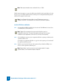
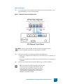
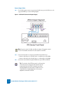
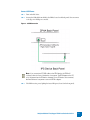
UnityOne
Modular Fiber/Copper ZPHA
Installation Guide
Version 2.1
Part Number: TECHD-0000000050
Publication Control Number: 021505
UnityOne™ is a registered trademark of TippingPoint Technologies, Inc. TippingPoint, TippingPoint
Technologies and the TippingPoint Technologies logo are also registered trademarks of TippingPoint
Technologies.
This document contains confidential information or trade secrets or both, which are the property of
TippingPoint Technologies, Inc. This document may not be copied, reproduced, or transmitted to
others in any matter, nor may any use of the information in this document be made, except for the
specific purposes for which it is transmitted to the recipient without the prior consent of TippingPoint
Technologies, Inc.
Copyright © 2005 TippingPoint, Inc.
Table of Contents
About This Guide
iii
Overview
Target Audience
Organization
Conventions
Headings
Typeface
Cross References
Messages
Related Documentation
Customer Support
iii
iii
iv
iv
iv
iv
iv
v
vii
viii
Prepare the Site
1
Overview
Safety Requirements
Rack and Clearance Requirements
Location
Environmental Requirements
Power Requirements
System Grounding Requirements
Cabling Requirements
Unpack the UnityOne ZPHA
ZPHA Installation
ZPHA Hardware Overview
ZPHA Installation
Cross-over Cable Installation
Index
1
1
2
2
2
2
3
3
3
5
6
9
14
19
UnityOne Modular Fiber/Copper ZPHA Installation Guide V 2.1
1
Table of Contents
2
UnityOne Modular Fiber/Copper ZPHA Installation Guide V 2.1
About This Guide
Explains who this book is intended for, how the information is organized, where information
updates can be found, and how to obtain customer support if you cannot resolve a problem.
Overview
Welcome to TippingPoint UnityOneTM Modular Fiber/Copper ZPHA Installation Guide. The UnityOne
Modular Zero Power High Availability device provides continued network traffic support in case an IPS
device loses power. The modular solution enables you to add a number of components for fiber and/or
copper as needed for your network environment.
This chapter includes the following sections:
•
•
•
•
•
“Target Audience” on page iii
“Organization” on page iv
“Conventions” on page iv
“Related Documentation” on page vii
“Customer Support” on page viii
Target Audience
This guide is intended for use by technicians and maintenance personnel responsible for installing,
configuring, and maintaining the UnityOne. Users should be familiar with telecommunications
products and networking concepts.
UnityOne Modular Fiber/Copper ZPHA Installation Guide V 2.1
iii
Organization
The UnityOne Modular Fiber/Copper ZPHA Installation Guide is organized as follows:
About the Guide
Explains who this book is intended for, how the information is organized, where information updates
can be found, and how to obtain customer support if you cannot resolve a problem.
Prepare the Site
Provides instructions for unpacking the Zero Power High Availability device and preparing your
network environment.
ZPHA Installation
Provides instructions for installing the Zero Power High Availability device for use with a UnityOne IPS
system.
Conventions
This book, and the other books in this series, follow some conventions for structuring information.
Headings
Every chapter starts with a brief description of the information you can find in that chapter, which
correlates with the major headings in that chapter. Each major heading corresponds to a task or
concept that is important for you to understand. Headings are of a different size and type to make them
easy to skim, whether you are viewing an online or print copy of this document.
Typeface
This book uses the following typeface conventions:
Bold
Code
Italic
Hyperlink
Used for the names of screen elements like buttons, drop-down lists, or fields. For
example, when you are done with a dialog, you would click the OK button.
Used for text a user must type to use the product.
Used for book titles, variables, and important term.
Used for web site and cross reference links.
Cross References
When a topic is covered in depth elsewhere in this guide, or in another book in this series, a cross
reference to the other information will be provided. Cross references within this book will take the
form: “for more information about conventions, see page 6, Conventions.” Cross references to other
publications will take the form: “for more information about <topic>, see Publication Name.”
iv
UnityOne Modular Fiber/Copper ZPHA Installation Guide V 2.1
Messages
Messages are special text that are emphasized by font, format, and icons. There are four types of
messages in this book:
•
•
•
•
Warning
Caution
Note
Tip
A description of each message type with an example message follows.
Warning
Warnings tell you how to avoid physical injury to people or equipment. For people, injury includes
anything from temporary conditions, such as pain, to irreversible conditions such as death. For
equipment, injury means anything requiring repair. Warnings tell you what you should or should not
do, and the consequences of not heeding the warning.
WARNING: Only trained and qualified personnel should install, replace, or
service this equipment. Disconnect the system before servicing.
Caution
Cautions tell you how to avoid a serious loss that stops short of physical damage such as the loss of data,
time, or security. Cautions tell you what you should or should not do to avoid such losses, and the
consequences of not heeding the caution.
CAUTION: Do not type del *.* from the root (C:\) directory. Typing del *.* from the root
directory will destroy all the program and configuration data that your computer needs to
run, and will render your system inoperable.
Note
Notes tell you about information that might not be obvious, or that does not relate directly to the
current topic, but that may affect relevant behavior.
Note: Most car rental companies no longer allow cash deposits in lieu of a credit
card when renting a car. Non-credit card deposits can only be arranged by a
lengthy application and approval process.
UnityOne Modular Fiber/Copper ZPHA Installation Guide V 2.1
v
Tip
Tips are suggestions about how you can perform a task more easily or more efficiently.
Tip: Setting the logging parameter to “off” or “minimal” will improve your
system’s processing performance, but it will make debugging very difficult in the
event of a system crash. During system integration, you can set logging to “full” to
ease debugging. After you have finished testing, set logging to “minimal” to
improve performance.
vi
UnityOne Modular Fiber/Copper ZPHA Installation Guide V 2.1
Related Documentation
The UnityOne systems have a full set of documentation. These publications are available in electronic
format on your installation CDs. For the most recent updates, check the Threat Management Center
(TMC) web site at https://tmc.tippingpoint.com.
Table 2 - 1: UnityOne Documents
Audience
Hardware
Technicians
Publication
•
•
•
•
•
•
Quick Start UnityOne-50
Quick Start UnityOne-50 Thumbdrive
Quick Start UnityOne-100E
Quick Start UnityOne-100E Thumbdrive
Quick Start UnityOne-5000E
Quick Start UnityOne 200/400/1200/2400
Location
printed version in the UnityOne box,
UnityOne Documentation CD,
https://tmc.tippingpoint.com
• UnityOne-50 Installation and Configuration
Guide
• UnityOne-50 Thumbdrive Installation and
Configuration Guide
• UnityOne-100E Installation and Configuration
Guide
• UnityOne-100E Thumbdrive Installation and
Configuration Guide
• UnityOne-5000E Installation and
Configuration Guide
• UnityOne 200/400/1200/2400 Installation and
Configuration Guide
• UnityOne Zero Power High Availability
Installation Guide
• UnityOne Modular Fiber/Copper ZPHA
Installation Guide
UnityOne Documentation CD,
UnityOne Security Manager System Quick Start
Guide
printed version in the UnityOne box,
UnityOne Documentation CD,
https://tmc.tippingpoint.com,
SMS server
https://tmc.tippingpoint.com
UnityOne Modular Fiber/Copper ZPHA Installation Guide V 2.1
vii
Table 2 - 1: UnityOne Documents
System
Administrators
UnityOne Local Security Manager User’s Guide
UnityOne Documentation CD,
https://tmc.tippingpoint.com
UnityOne Local Security Manager Online Help
available in the LSM application
Unity One Command Line Interface Reference
UnityOne Documentation CD,
https://tmc.tippingpoint.com
UnityOne Security Manager System Quick Start
Guide
hard copy in the shipping materials,
UnityOne Documentation CD,
https://tmc.tippingpoint.com
UnityOne Security Management System User’s
Guide
UnityOne Documentation CD,
https://tmc.tippingpoint.com
and on the SMS server
UnityOne Security Management System Online
Online Help
available in the SMS application
UnityOne SMS Web Services API
UnityOne Documentation CD,
https://tmc.tippingpoint.com
and on the SMS server
Third Party Management for UnityOne IPS
UnityOne Documentation CD,
https://tmc.tippingpoint.com
Customer Support
The TippingPoint technical support phone number is 1-866-681-8324 (866-681-TECH).
TippingPoint is committed to providing quality customer support to all of its customers. Each
customer is provided with a customized support agreement that provides detailed customer and
support contact information. For the most efficient resolution of your problem, please take a moment
to gather some basic information from your records and from your system before contacting TP
customer support.
Table 3: Customer Support Information
Information
viii
Location
Your customer number
You can find this number on your Customer Support Agreement and on
the shipping invoice that came with your UnityOne system.
Your IPS serial number
You can find this number on the shipping invoice that came with your
UnityOne system.
Your IPS software version
number
You can find this information in the LSM in the System Stats frame, in the
Update tab, or by using the CLI show version command.
Your IPS system boot time
You can find this information in the LSM in the System Stats frame.
UnityOne Modular Fiber/Copper ZPHA Installation Guide V 2.1
Table 3: Customer Support Information
Information
Your ZPHA serial number
Location
You can fine this number on the shipping invoice that came with your
UnityOne system.
UnityOne Modular Fiber/Copper ZPHA Installation Guide V 2.1
ix
x
UnityOne Modular Fiber/Copper ZPHA Installation Guide V 2.1
1
Prepare the Site
This chapter discusses the requirements necessary to prepare your site for the installation of the
UnityOne ZPHA for IPS devices.
Overview
Before installing the new UnityOne, you need to gather materials and prepare the network and
hardware site. To carefully and correctly install the ZPHA component into your UnityOne system, you
must read through all preparation instructions and requirements.
The chapter consists of the following sections:
•
•
•
•
•
•
•
•
“Safety Requirements” on page 1
“Rack and Clearance Requirements” on page 2
“Location” on page 2
“Environmental Requirements” on page 2
“Power Requirements” on page 2
“System Grounding Requirements” on page 3
“Cabling Requirements” on page 3
“Unpack the UnityOne ZPHA” on page 3
Safety Requirements
If not properly installed and maintained, electrical circuitry equipment like the UnityOne IPS can pose
dangers to both personnel and equipment. To prevent accidents, adhere to the following guidelines to
ensure general safety:
• Wear safety glasses if you are working under conditions that might be hazardous to your eyes.
• There are no serviceable parts inside.
UnityOne Modular Fiber/Copper ZPHA Installation Guide V 2.1
1
Rack and Clearance Requirements
Tipping Point recommends that you mount the UnityOne system in a standard 19-or 23-inch rack. The
vertical hole spacing on the rack rails must meet standard EIA-310-C requirements, which call for a
one inch (2.54 cm) spacing.
Location
The ZPHA should be located near the IPS device in the rack. The device connects to the IPS through
the following:
• USB cable for power
• Network cables (fiber or copper) to receive and transmit network traffic.
When planning the location of the ZPHA, consider the amount of IPS devices you may connect. You
can connect up to 5 segments to the ZPHA, depending on the segment components you purchase.
The ZPHA requires only one USB connection for power. The modular ZPHA provides 2 ports (1 type A
and 1 type B) on the back panel.
Environmental Requirements
In order for the UnityOne to run properly, your environment must meet the proper criteria.
The following table details the recommendations for temperature, humidity, and altitude settings for
the Service Provider (SP) environment.
Table 1 - 1: Environmental Requirements for the UnityOne
Environmental
Specifications
Description
Temperature
0 to 40 ° C (32 to 104 ° F) — Operating
-20 to 80° C (-4 to 176 ° F) — Storage
Humidity
5 to 95% (non-condensing)
Altitude
No degradation up to 13K feet above sea level
Power Requirements
The UnityOne ZPHA receives power through a USB cable connected to the IPS device. The modular
ZPHA comes with 1 USB cable. The back panel of the device provides two USB connections (1 type A
and 1 type B) , but only one connection is required for proper functioning. You should only attach IPS
devices to these USB ports. The ZPHA does not require any other type of power connection to
function.
2
UnityOne Modular Fiber/Copper ZPHA Installation Guide V 2.1
System Grounding Requirements
Damage from Electromagnetic Static Discharge (ESD) can occur when electronic components are
improperly handled. Its results can be complete or intermittent system failures. Therefore, proper ESD
protection is required whenever you handle IPS devices and equipment. It is not necessary to open the
UnityOne ZPHA chassis to add or remove any components.
Note: When you install the ZPHA, you do not need to modify or open the IPS
chassis. You will only need to connect cables during installation procedures.
Cabling Requirements
The UnityOne ZPHA requires the following cables:
• USB cable — 1 cable for connecting to the IPS to receive power (included with device)
• RJ-45 copper network cables — 4 cables are required per segment:2 for IPS connections and 2 for
network connections. (cables not included)
• LC-LC Simplex Multi-mode Fiber cables — 4 per segment (included with device). Additionally, you
should have 4 cables currently with your IPS device to connect to the ZPHA and/or Ethernet switch.
Note: For Simplex Single-mode Fiber cables, contact a TippingPoint Sales
Representative.
Unpack the UnityOne ZPHA
Each system chassis is securely packaged in a shipping box.
CAUTION: ESD can damage the UnityOne if you do not take necessary precautions.
Installation and maintenance personnel should be properly grounded using ground straps to
eliminate the risk of ESD damage to the equipment.
Use caution when opening the UnityOne boxes.
To unpack the ZPHA system, complete the following steps:
STEP 1
Inspect the packing container. If you see any damage or other signs of mishandling, inform
both the local freight provider and TippingPoint before unpacking. Your freight provider can
provide you with the procedures necessary to file a claim for damages.
STEP 2
Carefully open the box.
STEP 3
Remove all packing material.
STEP 4
Verify the contents in the shipping package. Compare the packing list to your shipment and to
your order. Are all items included? If items are missing, contact your TippingPoint sales or
field representative.
UnityOne Modular Fiber/Copper ZPHA Installation Guide V 2.1
3
4
STEP 5
Remove the chassis from the box.
STEP 6
Remove the segment modules from the box. You should receive a number of fiber or copper
modules as ordered including a number of blank faceplates for any remaining segment ports.
STEP 7
Open the accessory kit. It contains the cables, documentation, and management software.
STEP 8
Inspect all the equipment inside for damage. If you think any equipment might be damaged,
contact your freight provider for how to lodge a damage claim. Also, contact your
TippingPoint sales or field representative for instructions.
UnityOne Modular Fiber/Copper ZPHA Installation Guide V 2.1
2
ZPHA Installation
Provides information for installing the modular Zero Power High Availability device for your
UnityOne IPS system.
Overview
The Zero Power High Availability (ZPHA) device enables the network traffic to continue to flow if the
IPS system has a loss in power. The modular components of the ZPHA enable you to provide support
and protection for both fiber and copper connections. By using the ZPHA device in your network
security system, you can continue network traffic and services in the following situations:
• If power is lost to the IPS device(s)
• If the IPS needs to reboot. Rebooting your IPS can take some time, during which the network traffic
will be halted.
WARNING: When the ZPHA bypasses the IPS device(s), network traffic is not
scanned or blocked. You should fix any IPS errors and return power to ensure all
traffic runs through the UnityOne system.
You can use the ZPHA to continue network traffic and services by bypassing the IPS entirely when the
power no longer feeds into the system, when you need to unplug the system, and to continue service
while the IPS reboots.
This chapter includes the following sections:
• “ZPHA Hardware Overview” on page 6
• “ZPHA Installation” on page 9
• “Cross-over Cable Installation” on page 14
UnityOne Modular Fiber/Copper ZPHA Installation Guide V 2.1
5
ZPHA Hardware Overview
The ZPHA is a chassis with five available segment ports for module fiber and copper components.
These segment modules include a set of relays for receiving and sending network traffic from a
network system, into the IPS device, and back out to a network system. The network system could be
an Ethernet switch, a single workstation, a server, or other network service. The following table lists the
chassis components.
Table 2 - 1: ZPHA Components
Component
Description
USB ports (2)
USB ports for connecting to the IPS. 2 USB ports (1 type A and 1 type B) are
located on the back panel.
Segments (5)
Each modular segment includes network ports and segment ports. The
segment ports connect to the segment ports of the IPS. The network ports
connect to the networked systems sending and receiving traffic via the device.
The modular ZPHA supports fiber and copper segment modules.
LED Status light
Indicates if the ZPHA is receiving power from the IPS device. Glows green
when it receives constant power. It remains unlit if it does not receive power.
The ZPHA receives power through the USB connection to the IPS. If the power through the USB cable
interrupts due to power supply failure, power loss, or unplugging, the ZPHA instantly switches to route
network traffic, bypassing the IPS connections. It provides two USB ports for connecting two IPS
devices.
Note: If you connect two IPS USB cables to the ZPHA device, the ZPHA will
continue to function if one of the devices loses power. The ZPHA bypasses the IPS
only if all power from the IPS devices interrupts. If two IPS devices are connected,
both would have to lose power to cause the ZPHA to bypass.
The ZPHA can accept network connections for up to five (5) network segments. Each connection area
is called a segment. You can insert any combination (up to five) of fiber and copper segment
components. Any remaining segment ports can be covered with blank faceplates. At any time, you can
order additional modular segment components to add to your modular ZPHA.
Tip: The activation of the ZPHA may result in a link transition
in the same way that a link goes down and then up. Even
though switching of the ZPHA is extremely fast, certain
network equipment can take longer to establish link. You
should take note of required link times of the network
equipment connected to the ZPHA.
6
UnityOne Modular Fiber/Copper ZPHA Installation Guide V 2.1
The following image displays the front panel of the ZPHA without segment modules. The LED light is
located at the right-side of the front panel.
Figure 2 - 1: Modular ZPHA Front Panel (without segments)
The following image displays the front panel of the ZPHA filled with segment modules. This example
displays 2 copper segments, 2 fiber segments, and one blank faceplate segment. You can purchase and
install any variety of combinations of copper and fiber segment modules. Any empty modules will
come with blank faceplates. You can purchase and install new modules to replace existing or empty
segment modules.
Figure 2 - 2: Modular ZPHA Front Panel (with segments)
UnityOne Modular Fiber/Copper ZPHA Installation Guide V 2.1
7
The following image displays the Fiber Segment Module.
Figure 2 - 3: Fiber Segment Module
The following image displays the Copper Segment Module.
Figure 2 - 4: Copper Segment Module
8
UnityOne Modular Fiber/Copper ZPHA Installation Guide V 2.1
The following image displays the Blank Faceplate Segment Module.
Figure 2 - 5: Blank Faceplate Segment Module
The following image displays USB ports located on the ZPHA back panel.
Figure 2 - 6: USB Ports Back Panel
ZPHA Installation
When you install the ZPHA, you need the following components:
• USB cable — 1 cable for connecting to the IPS to receive power (included with device). The modular
ZPHA provides 2 USB ports (1 type A and 1 type B) on the back panel.
• RJ-45 copper network cables — 4 per segment (cables not included)
• LC-LC Simplex Multi-mode Fiber cable — 4 per segment (included with device). You should have 4
cables currently with your IPS device to connect to the ZPHA.
Note: For Simplex Single-mode Fiber cables, contact a TippingPoint Sales
Representative.
UnityOne Modular Fiber/Copper ZPHA Installation Guide V 2.1
9
Note: Fiber segment modules have a maximum link loss of 1.5db.
The IPS connection requires two copper or four fiber network cables for the Seg A and B ports. You also
need two copper or four fiber cables for the Net A and B ports for receiving and transferring network
traffic in your company’s network system.
Note: You will need a full set of cables for every IPS device you connect to a
segment of the ZPHA. The ZPHA device can connect five (5) IPS device segments.
Install the ZPHA Case and Modules
STEP 1
After unpacking the ZPHA, install the device into the rack. The ZPHA must be located close
to the IPS devices to be networked to it.
Note: Tipping Point recommends that you mount the UnityOne system in a
standard 19-or 23-inch rack. The vertical hole spacing on the rack rails must meet
standard EIA-310-C requirements, which call for a one inch (2.54 cm) spacing.
STEP 2
After installing the system case, place a segment module into a segment port. Make sure the
segment module is secure.
You can place one segment module (fiber or copper) into each segment port. You can install
the segment modules in any order.
STEP 3
Turn the screw located at the bottom of the segment with your thumb or a Phillips screw
driver to lock the segment module in the port.
Note: Repeat Steps 2 and 3 as necessary for each segment module. For empty
segment modules, install the blank faceplate component.
10
UnityOne Modular Fiber/Copper ZPHA Installation Guide V 2.1
Connect Fiber Cables
STEP 1
For each IPS segment, connect the fiber network cables from a port in the IPS device to the
appropriate ZPHA port. See the following diagram.
Figure 2 - 7: ZPHA to IPS Connection Diagram (Fiber)
Note: You must connect all cables according to segment. All segment connects
for one IPS should be connected to the same segment on the ZPHA.
STEP 2
Connect the IPS cables for routing network traffic through the IPS device.
STEP 3
• Connect a pair of Simplex network cables from port A of the IPS device to a segment A port
of the ZPHA.
• Connect a pair of Simplex network cables from port B of the IPS device to a segment B port
of the ZPHA.
Connect a pair of Simplex cables through the ZPHA device ports NET A and NET B.
Tip: The activation of the ZPHA may result in a link transition
in the same way that a link goes down and then up. Even
though switching of the ZPHA is extremely fast, certain
network equipment can take longer to establish link. You
should take note of required link times of the network
equipment connected to the ZPHA.
UnityOne Modular Fiber/Copper ZPHA Installation Guide V 2.1
11
Connect Copper Cables
STEP 1
For each IPS segment, connect a copper network cable from a port in the IPS device to the
appropriate ZPHA port. See the following diagram.
Figure 2 - 8: ZPHA to IPS Connection Diagram (Copper)
Note: You must connect all cables according to segment. All segment connects
for one IPS should be connected to the same segment on the ZPHA.
STEP 2
Connect the IPS cables for routing network traffic through the IPS device.
STEP 3
• Connect a cable from port A of the IPS device to a segment A port of the ZPHA.
• Connect a cable from port B of the IPS device to a segment B port of the ZPHA.
Connect the network cables through the ZPHA device ports NET A and NET B.
Tip: The activation of the ZPHA may result in a link transition
in the same way that a link goes down and then up. Even
though switching of the ZPHA is extremely fast, certain
network equipment can take longer to establish link. You
should take note of required link times of the network
equipment connected to the ZPHA.
12
UnityOne Modular Fiber/Copper ZPHA Installation Guide V 2.1
Connect USB Power
STEP 1
Turn on the IPS device.
STEP 2
Connect the USB cable from the IPS to the ZPHA, located on the back panels. You can connect
to the Type A or B USB port as needed.
Figure 2 - 9: USB Connection
Note: If you connect two IPS USB cables to the ZPHA device, the ZPHA will
continue to function if one of the devices loses power. The ZPHA bypasses the IPS
only if all power from the IPS devices interrupts. If two IPS devices are connected,
both would have to lose power to cause the ZPHA to bypass.
STEP 3
The ZPHA receives power, lighting the Status LED green (located on the front panel).
UnityOne Modular Fiber/Copper ZPHA Installation Guide V 2.1
13
Cross-over Cable Installation
You may need to use cross-over and straight cables depending on what two devices are being
connected to on a segment. You would use cross-over options typically is you are not connecting to an
Ethernet switch.
Internally, the ZPHA is a straight cable, whether in High Availability (HA) or normal mode. If you need
a cross-over to connect to the IPS, then you need a cross-over between the ZPHA and the IPS. In other
words, the cross-over must stay connected on the IPS side with an additional straight cable when the
ZPHA is added.
The following figures display alternate installations of the ZPHA when a cross-over is needed.
Whenever you have a cross-over connection coming in you must use a cross-over cable between the
ZPHA and the IPS and a straight cable from the ZPHA to the other device. See Figure 2 - 10, “ZPHA
Cross-over Configuration 1:
Figure 2 - 10: ZPHA Cross-over Configuration 1
14
UnityOne Modular Fiber/Copper ZPHA Installation Guide V 2.1
When you have a straight cable coming in, you can use two straight cables. If both connected devices
are end devices, you should use two cross-over cables. This is because when the ZPHA closes there
must be a crossover between the two connected devices. Without having the two crossover cables on
one side both cables between the two connected devices upon failure would be straight through and the
connection would not complete. See Figure 2 - 11, “ZPHA Cross-over Configuration 2:
Figure 2 - 11: ZPHA Cross-over Configuration 2
If you have two end devices connected with two cross-over connections, you should configure the
cables as follows:
• One side must have a crossover cable between the IPS and ZPHA devices with a straight through
cable between the ZPHA and the connected device
• The other side should have a reversed setting with the cross-over cable connecting the ZPHA and the
other device
UnityOne Modular Fiber/Copper ZPHA Installation Guide V 2.1
15
This configuration places a cross-over connection between the two connected devices upon failure,
ensuring the connection remains continuous. Without the cross-over connection between the two
devices, it disrupts because the ZPHA is completely passive, only passing signal from pin to pin. See
Figure 2 - 12, “ZPHA Cross-over Configuration 3 and Figure 2 - 13, “ZPHA Cross-over Configuration 4.
Figure 2 - 12: ZPHA Cross-over Configuration 3
16
UnityOne Modular Fiber/Copper ZPHA Installation Guide V 2.1
Figure 2 - 13: ZPHA Cross-over Configuration 4
UnityOne Modular Fiber/Copper ZPHA Installation Guide V 2.1
17
18
UnityOne Modular Fiber/Copper ZPHA Installation Guide V 2.1
Index
C
ventilation 2
ZPHA 5, 9
connection
copper 12
fiber 11
USB 13
cross-over cables 14
diagram
connection
cabling requirements 3
copper segment 8
connect 12
customer support viii
E
copper 12
fiber 11
USB 13
Electromagnetic Static Discharge 3
environmental requirements 2
ESD 3
F
faceplate segment 9
fiber segment 8
connect 11
connection 11
front panel (w/ segments) 7
front panel (w/o segments) 7
G
cross-over 1
cross-over 2
cross-over 3
cross-over 4
14
15
16
17
L
conventions iv
caution v
note v
tip vi
warning v
customer support viii
organization iv
overview iii
related documentation vii
target audience iii
H
hardware overview 6
I
installation
prepare the site 1
cabling 3
environmental requirements 2
location 2
power requirements 2
rack and clearance 2
safety requirements 1
system grounding 3
unpacking 3
safety requirements 1
segment
copper 8
faceplate 9
fiber 8
system grounding requirements 3
T
technical support viii
U
unpacking 3
USB 6, 13
connect 13
V
LED 6
location 2
ventilation 2
M
guide
S
module
copper 8
faceplate 9
fiber 8
P
power requirements 2
prepare the site 1
cabling 3
environmental requirements 2
location 2
power requirements 2
rack and clearance 2
safety requirements 1
system grounding 3
unpacking 3
ventilation 2
R
Z
ZPHA 5
front panel 7
hardware overview 6
installation 9
connection
copper 12
fiber 11
USB 13
cross-over cables 14
diagram
connection
copper 12
fiber 11
USB 13
cross-over 1
cross-over 2
cross-over 3
cross-over 4
14
15
16
17
rack and clearance requirements 2
related documentation vii
requirements
cabling 3
environmental 2
power 2
rack and clearance 2
safety 1
system grounding 3
UnityOne Modular Fiber/Copper ZPHA Installation Guide V 2.1
19
20
UnityOne Modular Fiber/Copper ZPHA Installation Guide V 2.1