1
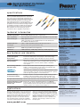
Keyed LC OptiCam ® Pre-Polished
Fiber Optic Connectors
SPECIFICATION SHEET
specifications
Keyed LC small form factor (SFF) pre-polished connectors
shall exceed TIA/EIA-568-B.3 performance requirements,
and contain a factory-terminated fiber, eliminating field
polishing and adhesive. Keyed LC pre-polished connectors
shall be mechanically keyed with color-specific positive
and negative keying features to prevent unintentional
mating with unlike keyed or non-keyed adapters. Keyed LC
pre-polished connectors shall have an average insertion
loss 0.3dB per mated pair for multimode and singlemode
fiber. Keyed LC pre-polished connectors shall captivate
fiber and buffer in one action allowing for up to two
re-terminations with no degradation in performance.
Keyed LC OptiCam ® Pre-Polished
Multimode Simplex Connectors
Keyed A (black):
FLCSMC^ABL
Keyed B (red):
FLCSMC^BRD
Keyed C (green):
FLCSMC^CGR
Keyed D (yellow):
FLCSMC^DYL
Keyed E (orange):
FLCSMC^EOR
Keyed F (dark blue): FLCSMC^FDB
Keyed LC OptiCam ® Pre-Polished
Singlemode Simplex Connectors
technical information
Standards requirements:
Exceed TIA/EIA-568-B.3 performance requirements
Fiber compatibility:
62.5/125µm OM1, 50/125µm OM2, 50/125µm OM3/OM4, 9/125µm OS1/OS2
Fiber size and type:
900µm tight-buffered fiber
250µm coated fiber, by using F250BT-C 250 micron fiber build-up tube
kit or FO6CB or FO12CB fan-out kit
Jacketed cable size:
1.6mm – 2.0mm and 3.0mm jacketed cable with optional boots
Ferrule type:
Zirconia ceramic with a pre-polished fiber stub
Insertion loss:
0.3dB average (multimode and singlemode)
Return loss:
>20dB (multimode), >26dB (10Gig ™ multimode), >50dB (singlemode)
Keyed A (black):
Keyed B (red):
Keyed C (green):
Keyed D (yellow):
Keyed E (orange):
Keyed F (dark blue):
FLCSSCABL
FLCSSCBRD
FLCSSCCGR
FLCSSCDYL
FLCSSCEOR
FLCSSCFDB
OptiCam ® 1.6/2.0mm Boots
Black boots:
FMCBT2BL-X*
OptiCam ® 3.0mm Boots
Black boots:
FMCBT3BL-X*
*X = Bag of 10 Boots; 100 per carton.
key features and benefits
Color-specific keys with
positive and negative
keying features
Mechanically and visually distinguish connections to prevent unintentional
insertion into unlike keyed or non-keyed ports, allow network design
flexibility and versatility, and accommodate more discrete networks
Factory pre-polished
fiber stub endface
Eliminates inconsistent and time-consuming field polishing to deliver
required optical performance; reduces termination time (less than half
the time of field polish connectors) and the number of installation
tools required
Dual cam design with fiber
and buffer clamps
Keyed LC Mini-Com ® Duplex Adapter
Modules (Ceramic Split Sleeves)
Secures both the fiber and the buffer during the camming step to
facilitate consistent termination results; reduces the termination time
compared to conventional termination methods
Allows up to two re-terminations to achieve optimum termination results;
reduces the number of rejected connectors and terminations to provide
yield rates approaching 100% for lower installed costs
Translucent housing
assembly (laser marked)
Facilitates inspection of the fiber termination quality, resulting in rapid
installations, improved termination yields, and lower installed costs;
laser marked to identify fiber stub fiber type (9µm, 62.5, 50, or 50X)
Non-optical disconnect design
Maintains data transmission under tensile loads for jacketed cable
Universal termination tool with
integrated visual termination
indicator (VTI)
Ensures fast, consistent, and optimal terminations of all OptiCam ®
Connectors with connector specific cradles; offers visual indication of
proper termination after the cam step has been completed to virtually
eliminate operator error to deliver a lower installed cost
w w w. p a n d u i t . c o m
Keyed A (black):
Keyed B (red):
Keyed C (green):
Keyed D (yellow):
Keyed E (orange):
Keyed F (dark blue):
CMDABLLCZ**
CMDBRDLCZ**
CMDCGRLCZ**
CMDDYLLCZ**
CMDEORLCZ**
CMDFDBLCZ**
Keyed LC Opticom ® Fiber Adapter Panels
(Ceramic Split Sleeves)
Keyed A (black):
FAP‡WABLDLCZ
Keyed B (red):
FAP‡WBRDDLCZ
Keyed C (green):
FAP‡WCGRDLCZ
Keyed D (yellow):
FAP‡WDYLDLCZ
Keyed E (orange):
FAP‡WEORDLCZ
Keyed F (dark blue): FAP‡WFDBDLCZ
LC Lock-in Duplex Clip
LC lock-in
FLCCLIW-X
duplex clip:
applications
Secure networks require a level of visual and
mechanical differentiation, and physical layer
security that conventional LC connector solutions
cannot provide. Typical applications for Keyed LC
OptiCam® Connectors include maintenance or
emergency restoration of secure fiber networks
and retrofit/initial install of behind the wall (BTW)
connections and the permanent side of interconnect
OptiCam ® Termination Tooling
OptiCam ®
Termination Kit:
FCAMKIT
OptiCam ® Conversion
Kit (upgrades
Opti-Crimp ® Kit to also
terminate OptiCam ®
Connectors):
FPPKIT-CVY
Field polish kit
upgrade (upgrades
field polish kit to also
terminate OptiCam ®
Connectors):
FIELDKITUPG
LC cradles (2 per pkg.): FLCC
and cross-connect patch fields. Keyed LC OptiCam
Connectors eliminate the need for endface polishing
and adhesive, enabling faster deployment, especially
in remote areas and confined spaces. The hand-held
OptiCam® Termination Tool gives installers the
flexibility to terminate in very close proximity to the
application without having to switch tools or find
benchtop space.
®
^Substitute for fiber type: 6 = 62.5/125µm OM1,
5 = 50/125µm OM2, X = 10Gig ™ 50/125µm
OM3/OM4 or 9 = 9/125µm OS1/OS2.
**Substitute for module color: AW for Arctic White,
BL for Black, BU for Blue, EI for Electric Ivory, or
IW for Off White.
‡Substitute for number of adapters: 6, 8, or 12.
Keyed LC OptiCam ® Pre-Polished Fiber Optic Connectors
performance information
Test Parameter
Qualification test suite
(TIA/EIA-568-B.3 requirements)
Repeated mating
Cable retention (straight pull):
900µm tight-buffered fiber
Jacketed cable
Description
Complete testing protocol per TIA/EIA-568-B.3 using TIA/EIA
FOTPs that include mechanical, environmental, and optical
test sequences
500 mate/unmate cycles
Max. insertion loss: 0.75dB
Min. return loss: 20dB
TIA/EIA-568-B.3 requirement:
0.5 lbs. load applied with <0.5dB increase in insertion loss
after test
11.24 lbs. load applied with <0.5dB increase in insertion loss
after test
Result
Exceeds TIA/EIA-568-B.3 requirements
Exceeds TIA-EIA-568-B.3 test requirements:
<0.1dB additional insertion loss
Exceeds TIA/EIA-568-B.3 requirements:
1.0 lbs. avg. load applied with <0.2dB increase in insertion
loss after test
11.24 lbs. load applied with <0.1dB increase in insertion loss
after test*
*Jacketed cable retention tensile load may vary based on specific manufacturer’s jacketed cable diameter and aramid yarn count.
ordering information
Key Type and
Backbone Color
(Adapter Key Shown)
Connector/
Cable Type
Boot
Color
Average
Insertion
Loss**
0.3dB
0.3dB
0.3dB
0.3dB
0.3dB
0.3dB
0.3dB
0.3dB
0.3dB
0.3dB
0.3dB
0.3dB
0.3dB
0.3dB
0.3dB
0.3dB
0.3dB
0.3dB
0.3dB
0.3dB
0.3dB
0.3dB
0.3dB
0.3dB
Ferrule
Finish
SPC
SPC
SPC
UPC
SPC
SPC
SPC
UPC
SPC
SPC
SPC
UPC
SPC
SPC
SPC
UPC
SPC
SPC
SPC
UPC
SPC
SPC
SPC
UPC
Part Number
Fiber Type
A - Black
FLCSMCXABL
10Gig ™ 50/125µm OM3/OM4
Simplex*/900µm
FLCSMC5ABL
50/125µm OM2
tight-buffered
Black
FLCSMC6ABL
62.5/125µm OM1
cable
FLCSSCABL
9/125µm OS1/OS2
B - Red
FLCSMCXBRD
10Gig ™ 50/125µm OM3/OM4
Simplex*/900µm
FLCSMC5BRD
50/125µm OM2
Black
tight-buffered
FLCSMC6BRD
62.5/125µm OM1
cable
FLCSSCBRD
9/125µm OS1/OS2
C - Green
FLCSMCXCGR
10Gig ™ 50/125µm OM3/OM4
Simplex*/900µm
FLCSMC5CGR
50/125µm OM2
tight-buffered
Black
FLCSMC6CGR
62.5/125µm OM1
cable
FLCSSCCGR
9/125µm OS1/OS2
D - Yellow
FLCSMCXDYL
10Gig ™ 50/125µm OM3/OM4
Simplex*/900µm
FLCSMC5DYL
50/125µm OM2
tight-buffered
Black
FLCSMC6DYL
62.5/125µm OM1
cable
FLCSSCDYL
9/125µm OS1/OS2
E - Orange
FLCSMCXEOR
10Gig ™ 50/125µm OM3/OM4
Simplex*/900µm
FLCSMC5EOR
50/125µm OM2
tight-buffered
Black
FLCSMC6EOR
62.5/125µm OM1
cable
FLCSSCEOR
9/125µm OS1/OS2
F - Dark Blue
FLCSMCXFDB
10Gig ™ 50/125µm OM3/OM4
Simplex*/900µm
FLCSMC5FDB
50/125µm OM2
Black
tight-buffered
FLCSMC6FDB
62.5/125µm OM1
cable
FLCSSCFDB
9/125µm OS1/OS2
*For duplex connectors, replace the first S in the part number with a D.
**All connector insertion loss values calculated from tests taken with precision launch jumper assemblies per TIA/EIA-FOTP-171.
Return
Loss
>26dB
>20dB
>20dB
>50dB
>26dB
>20dB
>20dB
>50dB
>26dB
>20dB
>20dB
>50dB
>26dB
>20dB
>20dB
>50dB
>26dB
>20dB
>20dB
>50dB
>26dB
>20dB
>20dB
>50dB
Keyed LC Mini-Com ® Fiber
Optic Adapter Modules
Keyed LC Opticom ® Fiber
Adapter Panels (FAPs)
Keyed LC Opti-Core ®
Patch Cords and Pigtails
LC Lock-In Duplex Clip
CMD***LCZIW
FAP6W***DLCZ
F^E10 ▲ -10▲M‡
FLCCLIW-X
***Substitute for key type and color: ABL for A – Black, BRD for B – Red, CGR for C – Green, DYL for D – Yellow, EOR for E – Orange, or FDB for F – Dark Blue.
^Substitute for fiber type: 6 = 62.5/125µm OM1, 5 = 50/125µm OM2, X = 10Gig ™ 50/125µm OM3/OM4 or 9 = 9/125µm OS1/OS2.
▲
Substitute for key type and color: A for A – Black, B for B – Red, C for C – Green, D for D – Yellow, E for E – Orange, or F for F – Dark Blue.
‡Substitute for length in meters: 1 – 10, 15, 20 or 30. Contact Customer Service for other available lengths or universal reference patch cords.
WORLDWIDE SUBSIDIARIES AND SALES OFFICES
PANDUIT CANADA
Markham, Ontario
[email protected]
Phone: 800.777.3300
PANDUIT EUROPE LTD.
London, UK
[email protected]
Phone: 44.20.8601.7200
PANDUIT SINGAPORE PTE. LTD.
Republic of Singapore
[email protected]
Phone: 65.6305.7575
PANDUIT JAPAN
Tokyo, Japan
[email protected]
Phone: 81.3.6863.6000
PANDUIT LATIN AMERICA
Jalisco, Mexico
[email protected]
Phone: 52.33.3777.6000
PANDUIT AUSTRALIA PTY. LTD.
Victoria, Australia
[email protected]
Phone: 61.3.9794.9020
For a copy of Panduit product warranties, log on to www.panduit.com/warranty
For more information
Visit us at www.panduit.com
Contact Customer Service by email: [email protected]
or by phone: 800-777-3300 and reference FBSP30
©2009 PANDUIT Corp.
ALL RIGHTS RESERVED.
WW-FBSP30
9/2009