1
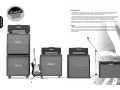
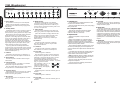
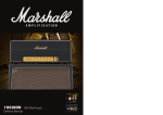
1959SLP
1987X
2245 ‘JTM45’
1962 ‘Bluesbreaker’
Marshall Amplification plc
Denbigh Road, Bletchley, Milton Keynes, MK1 1DQ, England
Tel : [01908] 375411 Fax : [01908] 376118
www.marshallamps.com
BOOK-00066-00 / 1 / 02
BOOK-00066-00 / 2 / 02
Whilst the information contained herein is correct at the time of publication,
due to our policy of constant improvement and development, Marshall
Amplification plc reserve the right to alter specifications without prior notice.
Owners Manual
!
WARNING! - Important safety instructions
A
PLEASE read this instruction manual carefully before switching on.
B
ALWAYS use the supplied mains lead, if a replacement is required please contact your authorised
Marshall Dealer.
C
NEVER attempt to bypass the fuses or fit ones of the incorrect value.
D
DO NOT attempt to remove the amplifier chassis, there are no user serviceable parts.
E
Refer all servicing to qualified service personnel including replacement of fuses and valves. Servicing is
required when the apparatus has been damaged in any way, such as when the power supply cord or plug is
damaged, liquid has been spilled or objects have fallen into the apparatus, the apparatus has been exposed to
rain or moisture, does not operate normally or has been dropped.
F
NEVER use an amplifier in damp or wet conditions. No objects filled with liquids should be placed on the
apparatus.
G
ALWAYS unplug this apparatus during lightning storms or if unused for long periods of time.
H
PROTECT the power cord from being walked on or pinched particularly at plugs, convenience receptacles and
at the point where they exit from the apparatus.
I
DO NOT switch the amplifier on without a loudspeaker connected.
J
ENSURE that any extension cabinets used are of the correct impedance.
From the Chairman
I would like to personally thank you for selecting one
of my vintage re-issue amplifiers.
The Marshall reputation has been built upon many
things, but our longevity comes mainly as a result of
the continual relevance of the concepts behind the
design and build of our amplifiers. Added to this are
solid workmanship, reliability, stylish looks, and above
all – great tone. The continual fascination and love that
many guitarists show for our vintage amplification is a
testament to just how relevant and important these
models still are today.
The amp you have just acquired was originally
launched in the 1960s. A time when the face and
sound of popular music was rapidly changing and
players were constantly pushing back the musical
boundaries. Each of these amps was there at the
beginning of this music revolution and all played their
part. From Pete Townshend, Eric Clapton and Jimi
Hendrix, to Jeff Beck and Paul Kossoff, the list of great
‘tone’ players who pioneered the use of the natural
distortion from these amps, reads like a who’s who of
guitar players.
Our re-issues of these models are as faithful as
possible to the originals in terms of looks and tone.
Hand-crafted in the UK these superb units feature
finger-jointed cabinets of birch plywood, hand-welded
chassis’s, hand-wired potentiometers and valve bases
and the highest quality PCBs and componentry.
I would like to wish you every success with your new
amplifier and welcome you to the family of great
players who use the classic Marshall tone.
➲ Note: This equipment has been tested and found to comply with the requirements of the EMC directive
(Environments E1, E2 and E3 EN 55103-1/2) and the Low Voltage directive in the E.U.
➲ EUROPE ONLY - Note:
The Peak Inrush current for the 1987X is 26 amps.
The Peak Inrush current for the 1959SLP is 38 amps.
The Peak Inrush current for the 1962 (Bluesbreaker) is 26 amps.
The Peak Inrush current for the 2245 (JTM45) is 26 amps.
➲ CAUTION: Any changes or modifications not expressly approved by the party responsible for compliance may
void the users authority to operate the equipment.
➲ Note: It is recommended that all audio cables, with the exception of the speaker lead, used to connect to the
1987X, 1959SLP, 1962 (Bluesbreaker) and the 2245 (JTM45) are of a high quality screened type. These should
not exceed 10 metres in length.
Always use a non-screened Marshall approved speaker lead when connecting an extension cabinet to these units.
➲ WARNING: Do not obstruct ventilation grilles and always ensure free movement of air around the amplifier!
USA ONLY - DO NOT defeat the purpose of the polarised or grounding type plug. A polarised plug has two
blades with one wider than the other. A grounding type plug has two blades and a third grounding prong.
The wide blade or the third prong are provided for your safety. When the provided plug does not fit into your
outlet, consult an electrician for replacement of the obsolete outlet.
FOLLOW ALL INSTRUCTIONS AND HEED ALL WARNINGS
KEEP THESE INSTRUCTIONS !
1
2
ENGLISH
ENGLISH
WARNING: THIS APPARATUS MUST BE EARTHED!
Introduction
The Marshall re-issue range consists of the 100 Watt 1959SLP head, the 50 Watt 1987X head,
the 2245 ‘JTM45’ head and 1962 ‘Bluesbreaker’ combo. All are faithful reproductions of the
originals, which shaped the sound of the electric guitar as we know it.
ENGLISH
FX Loop
Due to high demand, a sonically transparent effects loop has been added to the 1959SLP and
1987X models. This circuitry has been designed to not colour the guitar sound, so that your tone
remains pure. The bypass switch gives you the option of completely removing this circuitry if
desired. The effects loop level selector ensures compatibility with rack processors or floor pedals
(stomp boxes).
3
4
ENGLISH
The main characteristic that these amps share is their simplicity of operation and superb natural
valve tone. Achieving the beautifully organic and vibrant overdrive which is their trademark, can
only be done in one way – crank’em up! The result is pure, majestic tone uncluttered by
unnecessary circuitry. With solos this produces a big, round, warm sustain, full of classic
character. With chord work you get a bark and percussive attack with a natural sounding break up,
which allows each note to ring out in a glorious musical crunch.
1959SLP & 1987X
1959SLP Rear Panel
10
1959SLP & 1987X Front Panel
+4dBV
-10dBV
12
!
EFFECTS
LOOP
BYPASS
ACTIVE
STANDBY
PRESENCE
4
MK
II
2
8
0
ON
BASS
4
6
10
MIDDLE
4
6
2
8
0
2
10
TREBLE
4
6
8
0
10
HIGH TREBLE
4
6
2
8
0
10
ON
2
8
0
10
LOUDNESS 1
1
6
2
2
10
MAINS INPUT
OUTPUT
MAINS
110V ~ 60Hz
375 Watts
atts
7
8
9
MAINS FUSE
T3.15A 230V
T6.3A 110V
H.T. FUSE
T1A
OUTPUT: 100 WATTS RMS
AND.
10
11
INPUTS
8
0
SELECTOR
CONNECT SPEAKERS BEFORE USE
SEND
RETURN
NORMAL
4
6
SELECTOR
SPEAKERS
LEVEL BYPASS
MAINS
WARNING!: RISK OF HAZARDOUS ENERGY
AVIS!: ENERGIE ELECTRIQUE DANGEREUSE!
1
2
LOUDNESS 2
1 2
3
4
5
6
MODEL: 1987X
1
2
3
4
5
6
1. Power Switch
7
8
9
11
13
7. Treble Control
On / Off Switch for mains power to the amplifier.
+4dBV
-10dBV
LEVEL BYPASS
RETURN
Controls the high frequencies of the guitar tone,
making your guitar sound brighter when increased.
Please ensure the amplifier is switched off and
unplugged from the mains electricity supply before
being moved.
2. Standby Switch
The Standby Switch is used in conjunction with the
Power Switch (item 1) to ‘warm up’ the amplifier
before use and to prolong the life of the output valves.
(Note: The tone network is highly interactive and
altering one control can change the shape of the
sound in relation to the other tone controls.
Experimentation is the best way to achieve your
desired sounds.)
8. High Treble Loudness 1
Controls the overall output level of Channel 1.
Note: This channel is voiced for a higher treble
response than Channel 2.
When powering up the amplifier always engage the
Power Switch (item 1) first. This allows the
application of the voltage required to heat the valves
to their correct operating temperature. After about 2
minutes, when the valves are up to the correct
temperature, the Standby Switch can be engaged.
Upon doing this the H.T. (High Tension) which is the
high voltage required by the output valves to pass
signal (and hence produce sound) is applied.
9. Normal Loudness 2
Controls the overall output level of Channel 2.
Note: Channel 2 is voiced for normal response.
10. Input Jack
Connects the guitar to Channel 1.
To prolong valve life, the Standby Switch alone
should be used to turn the amplifier on and off during
breaks in a performance. Also, upon full power down,
always disengage the Standby Switch prior to the
main Power Switch (item 1).
3. Indicator
The Indicator will be lit when your amplifier is on
and will not be lit when the amplifier is switched off.
4. Presence Control
Adds higher frequencies to the guitar tone, creating
crispness and bite. Turning this up will make the
sound more cutting and ‘present’.
Note: Though the first input of the first channel is
the input that most guitarists use, don’t be afraid to
experiment. Some guitar players prefer to mix the two
channels together by connecting a short, screened
patch lead between the second input of Channel 1 and
the first input of Channel 2. If you then plug your
guitar into the first input of
Channel 1 (item 10), you can mix 1
2
the different tonal characters of
INPUTS
each channel for greater
1
2
flexibility. (See diagram).
11. Input Jack
Connects the guitar to the lower sensitivity input on
Channel 1.
5. Bass Control
Controls the amount of low frequencies or bottom
end in your tone.
12. Input Jack
Connects the guitar to Channel 2.
6. Middle Control
13. Input Jack
Dictates the middle register of the amplifier.
Turning this up will make your guitar sound fatter.
Conversely reducing the amount of middle in your
tone will result in a sharper and thinner guitar sound
for a more ‘scooped’ tone.
Connects the guitar to the lower sensitivity input on
Channel 2.
EFFECTS
LOOP
BYPASS
ACTIVE
SEND
!
WARNING!: RISK OF HAZARDOUS ENERGY
AVIS!: ENERGIE ELECTRIQUE DANGEREUSE!
SELECTOR
SELECTOR
MAINS INPUT
OUTPUT
MAINS
110V ~ 60Hz
175 Watts
atts
7
8
9
SPEAKERS
3
4
5
6
1. Level
MADE IN ENGLAND BY MARSHALL AMPLIFICATION PLC,
BLETCHLEY, MILTON KEYNES, ENGLAND.
10
11
If running into two 16 Ohm cabs, the amp should be
set to 8 Ohms. If running into two 8 Ohm cabs, the
amp should be set to 4 Ohms.
Provides two different loop levels to suit the type of
effects connected to the series effects loop. The
higher level (+4dBV) suits rack processors and the
lower level (-10dBV) suits floor pedals.
Failure to comply with these points will result in
damage to the amplifier.
2. Bypass
Your amp should be completely powered down
before the selector is turned.
This switch completely bypasses the circuitry
involved in the effects loop to maintain absolute tonal
integrity.
8. Mains Selector
Matches the amplifier mains transformer voltage to
the incoming mains voltage. Ensure that the rotary
Mains Selector is set to the correct mains voltage
applicable to the country where used. If you do not
know the mains input voltage contact your authorised
Marshall dealer.
3/4. Effects Loop
To increase the flexibility of your amplifier further
you may choose to add external effects. The Effects
Loop allows direct connection of either floor pedals or
rack processors, with the level control (item 1)
providing the correct operating level.
Your amp should be completely powered down
before the selector is turned. Adjustment from
230/220V to 110V or vice versa will require the mains
fuse to be changed to the corresponding value as
detailed on the rear panel.
Usually effects involving distortion or Wah Wah
would not go through the loop, but between the guitar
and amp input. Time or modulation based effects
such as Chorus, Delay and Reverb are best suited to
the loop.
9. Mains Input
The signal is sent out from the amplifier to the input
of your effects processor/pedal from socket 4 (Effects
Send) then from the output of the processor/pedal is
returned into the amp via socket 3 (Effects Return).
Your amp is provided with a detachable mains
(power) lead which is connected here. The specific
mains input voltage rating that your amplifier has
been built for is shown on the back panel. Before
connecting for the first time, please ensure that your
amplifier is compatible with your electricity supply. If
you have any doubt, please get advice from a
qualified person. Your Marshall dealer will help in this
respect.
5/6. Loudspeaker Outputs
These are for connection to an external load, i.e.
speaker cabinet(s). (See item 7).
Please refer to Important Safety Instructions, page 2.
10. Mains Fuse
7. Output Selector
The correct value of mains fuse is specified on the
rear panel of the amplifier. Please refer to Important
Safety Instructions, page 2.
Matches the amplifier’s output to the load
impedance.
With all-valve amplifiers it is imperative that the amp
is connected to a load whilst in operation and that the
impedance selected on the amplifier matches the total
impedance of the speaker cabinet(s) being used. For
example, if the amp is running into a single 16 Ohm
cab, the amp should accordingly be set to 16 Ohms.
5
H.T. FUSE
T500mA
CONNECT SPEAKERS BEFORE USE
OUTPUT: 50 WATTS RMS
1 2
MAINS FUSE
T2A 230V
T4A 110V
11. H.T. Fuse
The correct value of H.T. fuse is specified on the
rear panel of the amplifier. Please refer to Important
Safety Instructions, page 2.
6
ENGLISH
ENGLISH
1987X Rear Panel
1962 (Bluesbreaker)
12
1962 Front Panel
14
1962 Rear Panel
!
MAINS
STANDBY
SPEED
JTM
6
0
10
2
ON
1
8
4
6
0
10
2
PRESENCE
8
4
6
0
10
2
BASS
8
MIDDLE
4
6
0
10
2
8
4
6
0
10
2
8
TREBLE
VOLUME I
VOLUME II
4
6
4
6
4
6
0
10
0
10
0
10
2
8
2
8
2
1
1
4
5
6
7
1. Power Switch
8
9
10
11
13
15
8. Middle Control
On / Off Switch for mains power to the amplifier.
Dictates the middle register of the amplifier.
Turning this up will make your guitar sound fatter.
Conversely reducing the amount of middle in your
tone will result in a sharper and thinner guitar sound
for a more ‘scooped’ tone.
Please ensure the amplifier is switched off and
unplugged from the mains electricity supply before
being moved.
2. Standby Switch
The Standby Switch is used in conjunction with the
Power Switch (item 1) to ‘warm up’ the amplifier
before use and to prolong the life of the output valves.
9. Treble Control
Controls the high frequencies of the guitar tone,
making your guitar sound brighter when increased.
(Note: The tone network is highly interactive and
altering one control can change the shape of the
sound in relation to the other tone controls.
Experimentation is the best way to achieve your
desired sounds.)
When powering up the amplifier always engage the
Power Switch (item 1) first. This allows the
application of the voltage required to heat the valves
to their correct operating temperature. After about 2
minutes, when the valves are up to the correct
temperature, the Standby Switch can be engaged.
Upon doing this the H.T. (High Tension) which is the
high voltage required by the output valves to pass
signal (and hence produce sound) is applied.
10. Volume I
Controls the overall output level of Channel 1.
Note: This channel is voiced for a higher treble
response than Channel 2.
To prolong valve life, the Standby Switch alone
should be used to turn the amplifier on and off during
breaks in a performance. Also, upon full power down,
always disengage the Standby Switch prior to the
main Power Switch (item 1).
11. Volume II
Controls the overall output level of Channel 2.
Note: Channel 2 is voiced for normal response.
12. Input Jack
Connects the guitar to Channel 1.
3. Indicator
The Indicator will be lit when your amplifier is on
and will not be lit when the amplifier is switched off.
4. Speed Control
Controls the speed of oscillation when using the
tremelo effect.
5. Intensity Control
Controls the intensity of oscillation (i.e. the effect
depth) when using the tremelo effect.
Note: The tremelo effect will only work when playing
through Channel 2 of the Bluesbreaker combo.
6. Presence Control
Note: Though the first input of the first channel is
the input that most guitarists use, don’t be afraid to
experiment. Some guitar players prefer to mix the
two channels together by connecting a short,
screened patch lead between the second input of
Channel 1 and the first input of Channel 2. If you then
plug your guitar into the first
input of Channel 1 (item 12), you 1
2
can mix the different tonal
INPUTS
characters of each channel for
1
2
greater flexibility. (See diagram).
FOOTPEDAL
1
2
3
1. Footpedal Jack
T500 mA
117V ~ 60Hz
175 Watts
T1.6A 230V
T3.15A 117V
4
5
6
7
The correct value of H.T. fuse is specified on the
rear panel of the amplifier. Please refer to Important
Safety Instructions, page 2.
Note: The tremelo effect will only work when playing
through Channel 2.
6. Mains Input
Your amp is provided with a detachable mains
(power) lead which is connected here. The specific
mains input voltage rating that your amplifier has
been built for is shown on the back panel. Before
connecting for the first time, please ensure that your
amplifier is compatible with your electricity supply. If
you have any doubt, please get advice from a
qualified person. Your Marshall dealer will help in this
respect.
2/3. Loudspeaker Outputs
These are for connection to either the internal
speakers and/or an external load, i.e. speaker
extension cabinet(s). (See item 4).
4. Output Selector
Matches the amplifier’s output to the load
impedance.
With all-valve amplifiers it is imperative that the
amplifier is connected to a load whilst in operation
and that the impedance selected on the amplifier
matches the total impedance of the internal speakers
and/or extension speaker cabinets.
7. Mains Fuse
The correct value of mains fuse is specified on the
rear panel of the amplifier. Please refer to Important
Safety Instructions, page 2.
The two internal speakers are 16 Ohms each. These
are wired in parallel giving an overall impedance of
8 Ohms, therefore the output selector should be set to
8 Ohms.
If an additional 8 Ohm extension speaker cabinet is
used in conjunction with the internal speakers the
output selector should be set to 4 Ohms.
Note: No additional extension speaker cabinet with
an impedance lower than 8 Ohms should be used in
conjunction with the internal speakers.
Failure to comply with these points will result in
damage to the amplifier.
Your amp should be completely powered down
before the selector is turned.
13. Input Jack
15. Input Jack
Connects the guitar to the lower sensitivity input on
Channel 2.
7
SELECTOR
5. H.T. Fuse
For connection of the supplied footswitch to allow
tremelo to be switched on and off.
Connects the guitar to Channel 2.
Controls the amount of low frequencies or bottom
end in your tone.
MAINS FUSE
OUTPUT: 30 WATTS RMS
14. Input Jack
7. Bass Control
MAINS INPUT
CONNECT SPEAKERS BEFORE USE
Connects the guitar to the lower sensitivity input on
Channel 1.
Adds higher frequencies to the guitar tone, creating
crispness and bite. Turning this up will make the
sound more cutting and ‘present’.
H.T. FUSE
2
MANUFACTURED BY
MARSHALL AMPLIFICATION PLC
BLETCHLEY, MILTON KEYNES, ENGLAND.
3
OUTPUT
SPEAKERS
INPUTS
8
ON
2
WARNING!: RISK OF HAZARDOUS ENERGY
AVIS!: ENERGIE ELECTRIQUE DANGEREUSE!
2
8
ENGLISH
ENGLISH
INTENSITY
4
2245 (JTM45)
10
2245 (JTM45) Front Panel
12
2245 (JTM45) Rear Panel
MODEL: JTM45
MAINS
STANDBY
PRESENCE
MK
II
6
0
10
2
ON
1
BASS
8
MIDDLE
4
6
0
10
2
8
4
6
0
10
2
TREBLE
8
4
6
0
10
2
8
ON
2
HIGH TREBLE
4
6
0
10
2
8
LOUDNESS 1
3
4
5
6
1. Power Switch
7
8
6
0
10
2
1
JTM
45
INPUTS
8
1
The Standby Switch is used in conjunction with the
Power Switch (item 1) to ‘warm up’ the amplifier
before use and to prolong the life of the output
valves.
11
Controls the overall output level of Channel 1.
Note: This channel is voiced for a higher treble
response than Channel 2.
9. Normal Loudness 2
Controls the overall output level of Channel 2.
Note: Channel 2 is voiced for normal response.
10. Input Jack
Connects the guitar to Channel 1.
Note: Though the first input of the first channel is
the input that most guitarists use, don’t be afraid to
experiment. Some guitar players prefer to mix the
two channels together by connecting a short,
screened patch lead between the second input of
Channel 1 and the first input of Channel 2. If you
then plug your guitar into the
first input of Channel 1 (item 10), 1
2
you can mix the different tonal
INPUTS
characters of each channel for
1
2
greater flexibility. (See diagram).
To prolong valve life, the Standby Switch alone
should be used to turn the amplifier on and off
during breaks in a performance. Also, upon full
power down always disengage the Standby Switch
prior to the main Power Switch (item 1).
3. Indicator
The Indicator will be lit when your amplifier is on
and will not be lit when the amplifier is switched off.
4. Presence Control
Adds higher frequencies to the guitar tone, creating
crispness and bite. Turning this up will make the
sound more cutting and ‘present’.
1
2
1/2. Loudspeaker Outputs
Please refer to Important Safety Instructions, page 2.
T1.6A 230V
T3.15A 117V
3
4
5
6
Your amp is provided with a detachable mains
(power) lead which is connected here. The specific
mains input voltage rating that your amplifier has
been built for is shown on the back panel. Before
connecting for the first time, please ensure that your
amplifier is compatible with your electricity supply. If
you have any doubt, please get advice from a
qualified person. Your Marshall dealer will help in this
respect.
Matches the amplifier’s output to the load
impedance.
With all-valve amplifiers it is imperative that the amp
is connected to a load whilst in operation and that the
impedance selected on the amp matches the total
impedance of the speaker cabinet(s) being used. For
example, if the amp is running into a single 16 Ohm
cab, the amp should accordingly be set to 16 Ohms.
If running into two 16 Ohm cabs, the amp should be
set to 8 Ohms. If running into two 8 Ohm cabs, the
amp should be set to 4 Ohms.
6. Mains Fuse
Failure to comply with these points will result in
damage to the amplifier.
Your amp should be completely powered down
before the selector is turned.
13. Input Jack
Connects the guitar to the lower sensitivity input on
Channel 2.
9
117V ~ 60Hz
175 Watts
5. Mains Input
3. Output Selector
Connects the guitar to Channel 2.
Dictates the middle register of the amplifier.
Turning this up will make your guitar sound fatter.
Conversely reducing the amount of middle in your
tone will result in a sharper and thinner guitar sound
for a more ‘scooped’ tone.
T500 mA
The correct value of H.T. fuse is specified on the
rear panel of the amplifier. Please refer to Important
Safety Instructions, page 2.
12. Input Jack
6. Middle Control
SELECTOR
4. H.T. Fuse
These are for connection to an external load, i.e.
speaker cabinet(s). (See item 3).
Connects the guitar to the lower sensitivity input on
Channel 1.
Controls the amount of low frequencies or bottom
end in your tone.
MAINS FUSE
CONNECT SPEAKERS BEFORE USE
11. Input Jack
5. Bass Control
MAINS INPUT
MANUFACTURED BY
MARSHALL AMPLIFICATION PLC
BLETCHLEY, MILTON KEYNES, ENGLAND.
13
8. High Treble Loudness 1
When powering up the amplifier always engage the
Power Switch (item 1) first. This allows the
application of the voltage required to heat the valves
to their correct operating temperature. After about 2
minutes, when the valves are up to the correct
temperature, the Standby Switch can be engaged.
Upon doing this the H.T. (High Tension) which is the
high voltage required by the output valves to pass
signal (and hence produce sound) is applied.
H.T. FUSE
OUTPUT: 30 WATTS RMS
(Note: The tone network is highly interactive and
altering one control can change the shape of the
sound in relation to the other tone controls.
Experimentation is the best way to achieve your
desired sounds.)
2. Standby Switch
JTM
45
2
LOUDNESS 2
9
OUTPUT
SPEAKERS
Controls the high frequencies of the guitar tone,
making your guitar sound brighter when increased.
Please ensure the amplifier is switched off and
unplugged from the mains electricity supply before
being moved.
WARNING!: RISK OF HAZARDOUS ENERGY
AVIS!: ENERGIE ELECTRIQUE DANGEREUSE!
2
7. Treble Control
On / Off Switch for mains power to the amplifier.
!
NORMAL
4
10
The correct value of mains fuse is specified on the
rear panel of the amplifier. Please refer to Important
Safety Instructions, page 2.
ENGLISH
ENGLISH
4