1
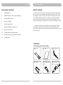
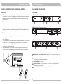
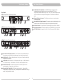
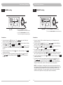
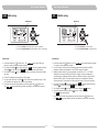
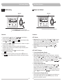
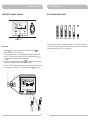
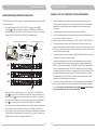
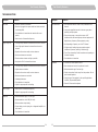
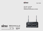
User Guide
ACT-71 / ACT-72 / ACT-74
Wideband True Diversity Receiver
All rights reserved. Do not copy or forward without prior approvals MIPRO.
Specifications and design subject to change without notice.
MN 014/07
2 CE 4 6 7 B
WARNING
IMPORTANT SAFETY INSTRUCTIONS
1.
Read these instructions.
2.
Keep these instructions.
3.
Heed all warnings.
4.
Follow all instructions.
5.
Do not use this apparatus near water.
6.
Clean only with a dry cloth.
7.
Do not block any ventilation openings. Install in accordance with the
manufacturer's instructions.
8.
Do not install near any heat sources such as radiators, heat registers,
stoves, or other apparatus (including amplifiers) that produce heat.
9.
Do not defeat the safety purpose of the polarised or ground plug: A
polarised plug has two blades with one wider than the other. The wide blade
is provided for your safety. When the provided plug does not fit into your
outlet, consult an electrician for replacement of the obsolete outlet.
1.
FOR OUTDOOR USE:
To reduce the risk of fire or electric shock, do not expose this apparatus to
rain or moisture.
2.
UNDER WET LOCATION:
Apparatus should not be exposed to dripping or splashing and no objects
filled with liquids, such as vases should be placed on the apparatus.
3.
SERVICE INSTRUCTIONS:
CAUTION - These servicing instructions are for use by qualified service
personnel only. To reduce the risk of electric shock, do not perform any
servicing other than that contained in the operating instructions unless you
are qualified to do so.
This symbol indicates that dangerous voltage constituting a risk
of electric shock is present within this unit.
10. Protect the power cord from being walked on or pinched particularly at plug,
convenience receptacles, and the point where they exit from the apparatus.
This symbol indicates that there are important operating and
maintenance instructions in the literature accompanying this unit.
11. Only use attachments/accessories specified by the manufacturer.
12. Use only with a cart, stand, tripod, bracket, or table specified
by the manufacturer, or sold with the apparatus. When a cart
is used, use caution when moving the cart/apparatus
combination to avoid injury from tip-over.
13. Unplug this apparatus during lightning storms or when unused
for long periods of time.
14. Refer all servicing to qualified service personnel. Servicing is required
when the apparatus has been damaged in any way, such as power-supply
cord or plug is damaged, liquid has been spilled or objects have fallen into
the apparatus, the apparatus has been exposed to rain or moisture, does not
operate normally, or has been dropped.
& IC - ID
THIS DEVICE COMPLIES WITH PART 15 OF THE FCC RULES AND RSS-123 ISSUE2 OF
CANADA. OPERATION IS SUBJECT TO THE FOLLOWING TWO CONDITIONS:
(1) This device may not cause interference.
(2) This device must accept any interference, including interference that may cause
undesired operation of the device. This equipment complies with FCC RF radiation
exposure limits set forth for an uncontrolled environment.
Disposal
15. To reduce the risk of fire or electric shock, do not expose this apparatus to
rain or moisture.
Disposing of used batteries with domestic waste is to be avoided!
16. Apparatus should not be exposed to dripping or splashing and no objects
filled with liquids, should be placed on the apparatus.
17. Use only with the battery which specified by manufacturer.
2005-08-13
18. The power supply cord set is to be the mains disconnected device.
Dispose of any unusable devices or batteries responsibly and in accordance
with any applicable regulations.
Batteries / NiCad cells often contain heavy metals such as cadmium(Cd),
mercury(Hg) and lead(Pb) that makes them unsuitable for disposal with
domestic waste. You may return spent batteries/ accumulators free of
charge to recycling centres or anywhere else batteries/accumulators are
sold.
By doing so, you contribute to the conservation of our environment!
Contents
True Diversity Receivers
TRUE DIVERSITY RECEIVERS
1
Product Overview
2
MIPRO'S Proprietary “ACT" Function & Operation
3
Part Names and Functions
6
Receiver Installation
8
Receiver Operation Tips
9
Rackmount Installation for Receivers
11
Receiver VFD Interface
22
Computer Network Interface Operation
23
General Tips for Improving System Performance
24
Troubleshooting
PRODUCT OVERVIEW
The ACT-71/ACT-72/ACT-74 receivers feature a full-color Vacuum Fluorescent Display
(VFD) which delivers a very bright light with exceptionally clear contrast. The VFD has a
wide viewing angle and can be viewed clearly in both indoor and outdoor environments.
Since it displays all pertinent parameters on the same screen, audio professionals can
clearly monitor group, channel, frequency, name, RF & audio signal strength, diversity
condition, transmitter battery level, squelch level and indication of interference at a glance.
True diversity technology ensures exceptionally long range for greatest RF reliability
and freedom of movement, while the industry's first AutoScan & Automatic Channel
Targeting (ACT) channel set-up technology and dual-squelch "PiloTone & NoiseLock" circuits
minimize interference.
ACCESSORIES
The following accessories are included:
Antenna × 2
Phone Cable × 1
0
1
User Guide × 1
AC Power Cord x 1
Audio Output Cable × 1
Rack-mount kit × 1 set
(ACT-71)
(ACT-71 1 half-rack)
True Diversity Receivers
True Diversity Receivers
MIPRO'S PROPRIETARY "ACT" FUNCTION & OPERATION
PART NAMES AND FUNCTIONS
What is ACT?
Front Panel:
!
“ACT” stands for “Automatic Channel Targeting”. MIPRO was the first manufacturer in
the industry to use infrared (IR) technology to automatically synchronize the frequency
selected on the receiver to any ACT handheld or bodypack transmitter on the same
frequency band.
ACT-71 Single-Channel True-Diversity Receiver
ON
!
Simple, fast and precise frequency set-up without mechanical errors.
!
Once the frequency has been set, the data is stored in memory, meaning that the
frequency is set until it is changed by performing the “ACT” function again, even after
powering off.
GRP
CHANNEL
CH
SET
FRQ NAME ADD
ACT
SQ
SET
1
1
No manual frequency adjusting needed, unlike traditional transmitters.
BA
B
SELECT
POWER
ACT Features
!
SET
L
A
3
2
5
4
ACT-72 Dual-Channel True-Diversity Receiver
ON
SET
L
A
BA
B
GRP
CHANNEL
CH
ACT
SET
FRQ NAME ADD
SQ
A
SET
BA
B
GRP
CHANNEL
1
CH
ACT
SET
FRQ NAME ADD
SQ
SET
2
SELECT
POWER
ACT Set-Up
1
!
Ensure a receiver channel is set up.
!
Press and release the “ACT” button to activate the ACT function. Once activated, the
word “ACT” appears.
!
Turn the transmitter’s power on and locate the transmitter infrared (IR) port and bring
it within 30cm (12”) of the receiver's ACT port. The receiver's IR port is a round
“window” located between the ACT & SET buttons. The transmitter IR port is normally
indicated by a round red colored spot.
!
ON
SET
A
BA
B
CHANNEL
GRP
CH
ACT
SET
FRQ NAME ADD
A
SQ
BA
B
GRP
CH
BA
B
CHANNEL
1
GRP
CH
ACT
SET
FRQ NAME ADD
SQ
SET
L
A
BA
B
CHANNEL
GRP
CH
ACT
SET
FRQ NAME ADD
L
SQ
A
SET
CHANNEL
2
3
GRP
CH
ACT
SET
FRQ NAME ADD
SQ
SET
A
BA
B
CHANNEL
GRP
CH
ACT
SET
FRQ NAME ADD
SQ
SET
4
SELECT
POWER
2
BA
B
3
4
5
1
Antenna “A” Front Mount: Allows an optional FBC-71 rear-to-front antenna cable
for front antenna placement.
2
Power Switch and Indicator: When the switch is turned on, the red indicator
illuminates to denote normal power status.
SQ
SET
1
POWER
SET
FRQ NAME ADD
5
SET
L
A
1
L
L
4
ACT-74 Four-Channel True-Diversity Receiver
When the frequencies are synchronized successfully between the transmitter and
receiver, the word “ACT” disappears and the original group and channel reappears.
ON
3
2
SELECT
ACT-717
CHANNEL
ACT
3
Receiver Display: Color VFDs.
4
Rotary Controller: To set up parameters. Move cursors by turning the control
clockwise or counterclockwise.
5
Antenna “B” Front Mount: Allows an optional FBC-71 rear-to-front antenna cable
for front antenna placement.
SET
1
<
30
cm
2
(1
in
.)
or
2
3
True Diversity Receivers
True Diversity Receivers
11
Unbalanced Audio Output Jack: ¼” PHONE PLUG type connector provides
unbalanced audio output signal from this jack to the mixer (ACT-71 only).
Output level is selectable from among 3 levels: “-6dB”, “0dB” and +10dB (the switch
will show +16dB on the receiver, but actually puts out +10dB on the unbalanced
jack).
12
Network Interface Connector: For linking the receivers to a computer systemmonitoring program.
13
Rear Antenna “A” Input Connector: The A antenna can be installed directly to this
antenna connector which also provides power to an optional antenna booster.
Rear Panel:
ACT-71 Single-Channel True-Diversity Receiver
10
6
8
11 16
14
12
15
13
ACT-72 Dual-Channel True-Diversity Receiver
BALANCED OUT
ANTENNA B
+8V DC BIAS
ANTENNA A
+8V DC BIAS
AC INPUT: 100~240V
12
13
14
REMOTE
ANTENNA A
+8V DC BIAS
AC INPUT: 100~240V
13
14
REMOTE
OUT
0dB
-6dB
IN
+16dB
14
AC Power Socket: The input socket for AC power ranging from 100VAC ~ 240VAC.
15
Rack-Mount Brackets: To install the receiver into a standard EIA 19-inch rack case.
16
LIFT/GND Switch: Lifts ground from Pin 1 of the XLR connector. (GND = default).
LIFT
GND
1
LEVEL
6
7
MIXED
8 16
CH 2
2
3
1: GND
2: HOT +
3: COLD -
CH 1
This connector can not be connected
to telecommunication networks.
10
9
ACT-74 Four-Channel True-Diversity Receiver
BALANCED OUT
ANTENNA B
+8V DC BIAS
0dB
-6dB
OUT
IN
+16dB
LIFT
GND
1
LEVEL
6
7
8 16
MIXED
9
CH 4
CH 3
CH 2
10
2
3
1: GND
2: HOT +
3: COLD -
CH 1
This connector can not be connected
to telecommunication networks.
12
6
Rear Antenna “B” Input Connector: The “B” antenna can be installed directly to
this antenna connector which also provides power to an optional antenna booster.
7
Ventilation Fan: Ensures stable performance in long hours of operation under high
temperature environments.
8
Level Switch: "0dB" selection is for "Microphone level" output. "+16dB" selection is
for “LINE level” output. “-6dB” selection is for half of cable microphone volume.
9
Mixed AF Output Jack: A balanced output jack for mixed AF signals from all
installed channels; 3 output levels to choose from.
10
Balanced Audio Output Jack: XLR type connector provides balanced audio
output signal from this jack to the mixer, and output level is selectable from among 3
levels: “-6dB”, “0dB” and “+16dB”.
4
5
True Diversity Receivers
True Diversity Receivers
RECEIVER INSTALLATION
8
14
BALANCED OUT
ANTENNA B
+8V DC BIAS
REMOTE
0dB
-6dB
Unbalanced Output: Using an audio output cable with ¼” “PHONE PLUG” type
connectors, connect one end from the unbalanced output jack 11 of the receiver,
and the other end to the “LINE-IN” input jack of the mixer or guitar amplifier, as
shown in Figure 2. (ACT-71 only)
OUT
IN
ANTENNA A
+8V DC BIAS
Balanced Output: Using audio output cables with “XLR” or “Cannon” type
connectors, connect one end to the balanced output jacks 10 of the receiver, and
the other end to the “MIC IN” input jack of the mixer or amplifier, as shown in
Figure 1. (The configuration of the 3-pin connector is as shown in Figure 3)
AC INPUT: 100~240V
+16dB
LIFT
GND
1
LEVEL
MIXED
6
CH 4
CH 3
CH 2
2
3
1: GND
2: HOT +
3: COLD -
CH 1
This connector can not be connected
to telecommunication networks.
13
10
11
2
1
GND
2
HOT +
3
COLD -
1
8
(Figure 1)
3
1.
2.
3.
Antenna Installation: Install 2 separate antennas on the antenna sockets
on the rear panel. Illustrated in Figure 1.
6
,
13
(Figure 2)
AC Power Operation: Connect the AC power cable to the AC Input Jack 14 , then
plug the other end into an AC outlet having the correct voltage and rating, as shown
in Figure 1.
(Figure 3)
Electric Guitar Output: Using audio output cable with ¼” “phone plug” type
connectors, plug one end into the unbalanced output jack of a receiver (ACT-71
only), and the other end into the input jack of a guitar amplifier. Switch the Level
Switch 8 to “+16dB” position (the switch will show “+16dB” on the receiver, but
actually puts out “+10dB” on the unbalanced jack).
Audio Output Connection:
Level Switch 8 Setting Position: When connecting from the receiver's
unbalanced ¼” output (ACT-71 only) to the "LINE-IN" jack of a mixer or an
electric guitar amplifier, switch the Level Switch 8 to the “+16dB” position. Low
sensitivity may occur if switched to the wrong level position; therefore, don't use
the “0dB” or “-6dB” positions as they may not deliver a sufficiently high level of
input. When connecting from a receiver's balanced output to the "MIC-IN" jack of
a mixer, switch the Level Switch 8 to the “0dB” position. Overload distortion may
occur if switched to the wrong level position. There are many different amplifiers
for Karaoke machines in today's market; however, the gain of many of these
amplifier's "MIC IN" is not consistent. Therefore, if distortion is encountered,
please switch the Level Switch 8 to the “-6dB” position.
Mixed Output: Balanced output socket (XLR) must connect to the balanced input
socket of the mixer. This output socket generates the mixed output of Ch.1~Ch.4
and the output sensitivity can be adjusted to “+16dB” or “0dB” or “-6dB” by the
level switch on the right side of the socket. (ACT-72/ACT-74)
6
7
True Diversity Receivers
True Diversity Receivers
RECEIVER OPERATING TIPS
RACKMOUNT INSTALLATION FOR RECEIVERS
! Prior to powering on the receiver, ensure all transmitters are turned off and the mixer's
volume control is set to a minimized setting. Red LED power indicator is lit when
powered on.
Single half-rack receiver
Install provided rack mount kit and fasten with screws on both sides. (Figure 4)
! Normally, the RF meter level glows when a transmitter is powered on to indicate the
receiver is ready for operation. Once an audio signal is received from the transmitter,
the AF meter level glows based on signal strength. If the meter or indicator does not
glow or there is no audio output, the system may not be set up properly. Re-check
that the transmitter is turned on and the receiver and transmitter are on the same
frequency (if not, the transmitter will need to be reset via the ACT function).
! The microphone output level needs to be adjusted at the mixer. There is no need to
adjust output levels at the receiver itself.
! The antenna inputs provide 8-volt DC biased and are designed to work with MIPRO
antenna boosters. If the connecting cable is longer than 10 meters (approx. 30'), it is
advisable to install an antenna booster to ensure optimal reception.
(Figure 4)
! Antenna dividers and receivers must be from the same frequency band.
Dual half-rack receivers
Unfasten the top and bottom screws for each receiver. Push the receivers next to each
other.
Place holding plates on top and bottom of the two receivers first, and following the
directions, slide both plates into position over the screw holes. Then tighten screws
(screws should be used in their original location; i.e., top screws for top holding plate
and bottom screws for bottom holding plate).
After both receivers are fixed together, fasten the rack mount kit on both sides of the
joined receivers as shown in Figure 5.
(Figure 5)
8
9
True Diversity Receivers
True Diversity Receivers
RECEIVER VFD INTERFACE
Receiver Rack-Mount Kits
FB-71
FB-72
Displays all Parameters
5
Mounts 1 half-rack in
a single rack space
14
1
7
13
Mounts 2 half-racks in
a single rack space
!
The rack mountable kits are pre-drilled with 4 opening holes to be fitted on an EIA
standard 19-inch rack case. (Figure 6)
!
For ideal reception and performance, install the receiver at least 1 meter (3 feet)
above the ground and away from EMI / RFI “noise” sources. In addition, place the
transmitter microphone at least 1 meter (3 feet) away from the receiving antenna, as
shown. (Figure 7)
(Figure 6)
3
2
8
11
12
! The screw size for rack mounted
function is as below:
10.00mm
Total 4 screws provided
10
11
9
Channel (can be programmed)
2
Audio Signal Meter
3
Diversity A/B Antenna
4
Working Frequency
5
RF Signal Meter
6
Interference Indicator (lit denotes presence of interference)
7
Frequency (can be programmed)
9
8
6
Battery Meter
Squelch Meter (levels can be programmed)
10
11
Group (can be programmed)
12
Name (can be programmed)
13
Lock Icon (can be turned on or off)
14
Setting Cursor
PC Address (can be programmed)
Display Panel and Buttons
! Please note the main disconnected
device is the AC Inlet
10
1
(Figure 7)
M4xP0.7mm
! L-Shaped steel bracket size for
rack mounted function:
4
True Diversity Receivers
True Diversity Receivers
Receiver Parameters
GRP
GROUP setting
Rotary Control Knob: To set parameter values
SET
6 parameters can be selected and programmed. See instructions below:
4
GRP
CH
FRQ
NAME
ADD
SQ
SELECT
GRP Cursor
Programmable Parameters:
NOTE: To confirm a parameter change and save it into the system, you must press the
button to end the flashing of the
cursor. If this step is missing, the new parameter is
not saved and will not be stored in the system when powered off.
Turn knob clockwise to increase values
Turn knob counterclockwise to decrease values
Instructions:
1. Press and release the
button once. The
cursor starts flashing to denote
it is ready to accept parameter changes.
2. Turn Rotary Controller 4 left or right and stop at GRP . Press and release the Rotary
Controller 4 once and current GRP number starts flashing.
3. Turn Rotary Controller 4 left or right to increase or decrease GRP numbers.
4. Press and release the Rotary Controller 4 once to confirm the change. The GRP
number stops flashing.
5. To confirm and save the new parameter, press and release the
button once.
The
cursor stops flashing and the new GRP number is now stored into
memory.
12
13
True Diversity Receivers
CH
True Diversity Receivers
FRQ
CHANNEL setting
FREQUENCY setting
SET
SET
4
4
SELECT
CH Cursor
SELECT
FRQ Cursor
Turn knob clockwise to auto scan
from beginning to the end of frequency band
Turn knob clockwise to increase frequency
Turn knob counterclockwise to decrease frequency
Turn knob counterclockwise to auto scan
from end to the beginning of frequency band
Instructions:
Instructions:
1. Press and release the
button once. The
cursor starts flashing to
denote it is ready to accept parameter changes.
2. Turn Rotary Controller 4 left or right and stop at CH . Press and release the Rotary
Controller 4 once and current CH number starts flashing.
3. Turn Rotary Controller 4 left or right to increase or decrease CH numbers. If there
is interference on your chosen CH, it will automatically jump to the next interferencefree CH.
4. Press and release the Rotary Controller 4 once to confirm the change. The CH
number stops flashing.
5. To confirm and save the new parameter, press and release the
button once.
The
cursor stops flashing and the new CH number is now stored into
memory.
1. Groups 16 contains 2,881 user-defined frequencies. Up to 16 frequencies can be
selected and stored.
2. Press and release the
button once. The
cursor starts flashing to
denote it is ready to accept parameter changes.
3. Turn Rotary Controller 4 left or right and stop at FRQ . Press and release the Rotary
Controller 4 once and the current FRQ number starts flashing.
4. Turn Rotary Controller 4 left or right to increase or decrease FRQ numbers in
increments of 1MHz (first 3 digits of the frequency #).
5. Press and release the Rotary Controller 4 again to confirm the first 3 digits, then turn
left or right to adjust the last 3 digits of the FRQ number in increments of 25 KHz.
6. Press and release the Rotary Controller 4 once more to confirm the change. The FRQ
number stops flashing.
7. To confirm and save the new parameter, press and release the
button once.
The
cursor stops flashing and the new FRQ number is now stored into
memory. If the new frequency is not one of the preset channels for that Group, the
display will show asterisks in place of the Group and Channel designations.
NOTE: If a new frequency is selected that is not among the preset channels for the
chosen Group, it MAY not be compatible with the other channels within that Group and
may potentially cause interference. If this occurs, the frequency will need to be
changed to avoid problems. The preset channels within each Group are specifically
selected to work together when using multiple systems simultaneously.
14
15
True Diversity Receivers
NAME
True Diversity Receivers
ADD
NAME setting
ADDRESS setting
NAME Cursor
ADD Cursor
SET
SET
4
4
SELECT
SELECT
Turn knob clockwise to increase letters, values, and symbols
Turn knob counterclockwise to decrease letters, values, and symbols
Turn knob clockwise to increase values
Turn knob counterclockwise to decrease values
Instructions:
Instructions:
1. Press and release the
button once. The
cursor starts flashing to
denote it is ready to accept parameter changes.
2. Turn Rotary Controller 4 left or right and stop at NAME . Press and release the Rotary
Controller 4 once and the current NAME alphanumeric characters start flashing.
3. Turn Rotary Controller 4 left or right for alphanumeric characters like numbers, letters
and signs.
4. A total of 6 alphanumeric characters can be changed.
5. Turn and press the Rotary Controller 4 once to confirm each character change. Once
all 6 characters are changed, the character stops flashing.
6. To confirm and save the new parameter, press and release the
button once.
The
cursor stops flashing and the new NAME is now stored into memory.
1. Press and release the
button once. The
cursor starts flashing to denote
it is ready to accept parameter changes.
2. Up to 64 receiver channels can be remotely monitored and controlled by MIPRO
proprietary software and hardware via its ACT-BUS computer interface.
3. Address numbers need to be pre-programmed in advance from “01 ~ 64” before
interfacing for network monitoring and control. However, to ensure networking is
working properly, all address numbers need to be different from each other to avoid
address conflicts. (Note: The same address number can be repeated for different
receiver channels IF a computer is not being used to control / monitor the systems.)
4. Turn Rotary Controller 4 left or right and stop at ADD . Press and release the Rotary
Controller 4 once and the current ADD number starts flashing.
5. Turn Rotary Controller 4 left or right to increase or decrease ADD numbers.
6. Press and release the Rotary Controller 4 once to confirm the change.
The ADD number stops flashing.
7. To confirm and save the new parameter, press and release the
button once.
The
cursor stops flashing and the new address is now stored into memory.
16
17
True Diversity Receivers
SQ
True Diversity Receivers
SQUELCH setting
L
Receiver Lock & Unlock
Lock cursor
SQ Cursor
SET
SET
4
4
SELECT
SELECT
Press and hold knob to lock and unlock the display panel
Turn knob clockwise to increase one segment at a time
Turn knob counterclockwise to decrease one segment at a time
Instructions:
Instructions:
1. Press and release the
button once. The
cursor starts flashing to
denote it is ready to accept parameter changes.
2. Turn Rotary Controller 4 left or right and stop at SQ . Press and release the Rotary
Controller 4 once and current SQ setting starts flashing.
3. Turn Rotary Controller 4 left to decrease sensitivity level by 1 indicator or turn right to
increase sensitivity level by 1 indicator.
4. The higher the level indicators, the lower the sensitivity which shortens the
transmission ranges. The lower the level indicators, the higher the sensitivity which
increases the transmission ranges.
5. Press and release the Rotary Controller 4 once to confirm the change.
The SQ number stops flashing.
6. To confirm and save the new parameter, press and release the
button once.
The
cursor stops flashing and the new SQ level is now stored into memory.
ACT-71 Receiver
18
1. Receiver Lock: Press and hold the Rotary Controller 4 until the “ L ” icon appears.
Release the Rotary Controller 4 immediately when the “ L ” icon appears. When
locked, the receiver parameters can no longer be changed. However, you can still
navigate the Rotary Control Knob to view existing settings and parameters.
2. Unlock Receiver: Press and hold the Rotary Controller 4 until the “ L ” icon
disappears. Release the Rotary Controller 4 immediately when the “ L ” icon
disappears.
ACT-72 & ACT-74 Receivers
1. To Lock or Unlock All Receiver Channels:
Same instructions as ACT-71 receiver. (See “1” above)
2. To Lock 1 Receiver Channel only: For example, locking Channel 1. Press & hold
Rotary Controller 4 until all “ L ” icons start flashing. Press & hold the
button
on Channel 1 when the “ L ” icon appears , then release the “Rotary Controller” and
button of Channel 1 simultaneously when the rest of the “ L ” icons in the other
channels disappear. Press & release the
button again while the
cursor
is flashing to confirm and save.
3. To Unlock 1 Receiver Channel only:
For example, unlocking Channel 1. Press & hold Rotary Controller 4 until all “ L ”
icons start flashing. Press & hold the
button on Channel 1 until the “ L ” icon
disappears, then release the “Rotary Controller” and
button of Channel 1
simultaneously when the rest of the “ L ” icons in the other channels appear. Press &
release the
button again while the
cursor is flashing to confirm and
save.
4. To Lock or Unlock 2~3 Channels (ACT-74):
Follow the same procedure as above, using the
button on each channel to set
the lock status as desired. (Note: This is easier if you keep an eye on the unset
channels' icons as they flash on and off.)
19
True Diversity Receivers
True Diversity Receivers
BA: Transmitter Battery Meter
Setting ACT transmitter frequency
SET
SELECT
Press ACT button
BA
BA
BA
BA
BA
BA
100%
90%
80%
40%
10%
0%
The battery meter is lit when the transmitter is powered on. The LCD battery meter gives
a % indication of remaining battery life, as shown above. Replace with new, fresh batteries
when battery indicators fall to 10% (1 level remaining).
Instructions:
1. Press the
button once to activate the syncing function. The word “
”
appears immediately on the receiver screen.
2. Turn the transmitter’s power on and bring handheld or bodypack transmitter within
30cm (12”) of the IR port on the receiver. The IR port is located between the
and
buttons. The frequency will sync automatically.
3. When the sync is done successfully, the word “
” will disappear from the receiver
screen and the transmitter LCD will show the group & channel.
4. The word “A--LOSE ” will appear on the receiver screen after 10 seconds if the syncing
was unsuccessful. To start the “ ACT ” syncing again, press the
button again.
L
ON
SET
L
A
BA
B
CHANNEL
GRP
CH
ACT
SET
FRQ NAME ADD
A
SQ
BA
B
GRP
CH
SET
FRQ NAME ADD
SQ
SET
1
POWER
SELECT
ACT-717
CHANNEL
ACT
SET
1
<
30
cm
(1
2
in
.)
or
20
21
True Diversity Receivers
True Diversity Receivers
COMPUTER NETWORK INTERFACE OPERATION
GENERAL TIPS FOR IMPROVING SYSTEM PERFORMANCE
1. MIPRO ACT receivers have an advanced computer network-interfaced controlling system.
1.
2. Wiring Instructions
!
The network interface of ACT-71/ACT-72/ACT-74 receivers is the ''REMOTE''
connector 12 that can be linked to a computer by a MIPRO-DVU or MIPRO-DVJ
hardware device. By using a RS-232 or USB connector, you can link to a computer
through the RS-232 COM PORT or USB PORT. (See diagram below)
Connect to keyboard jack on PC
Connect to RS-232 jack on PC
PC
Connector of keyboard
should plug in here
Connect to USB
jack on PC
BALANCED OUT
0dB
MIXED
CH 4
CH 3
MIXED
CH 4
CH 3
3
1: GND
2: HOT +
3: COLD -
CH 1
If extended reception distance is needed, installing a MIPRO directional antenna kit
(AT-90W) will increase the reception distance.
7.
Proper antenna distribution is vital to achieving ideal performance from multiple
wireless systems operating in the same environment. To greatly reduce antenna
clutter in multi-system installations, a MIPRO AD-707/AD-707a UHF antenna divider
system is recommended. Each AD-707/AD-707a supports up to four UHF diversity
receivers to operate from a single pair of antennas. When combined with an AT-70A
omnidirectional extension antenna and an AT-70B antenna booster or an AT-90W
directional antenna, the AD-707/AD-707a antenna divider provides optimal signal
reception with minimal dropouts or interference.
ANTENNA A
+8V DC BIAS
AC IN PUT: 1 00~240V
ANTENNA A
+8V DC BIAS
AC IN PUT: 1 00~240V
ANTENNA A
+8V DC BIAS
AC IN PUT: 1 00~240V
8.
Preset non-interfering channels within the same channel group are recommended to
ensure optimum performance from multiple wireless systems installed in the same
venue. Use of preset non-interfering channels from different channel groups
may cause interference, thus is not recommended.
This connector can not be connected
to telecommunication networks.
CH 2
2
3
1: GND
2: HOT +
3: COLD -
CH 1
IN
This connector can not be connected
to telecommunication networks.
REMOTE
OUT
0dB
IN
REMOTE
1
BALANCED OUT
ANTENNA B
+8V DC BIAS
-6dB
6.
+16dB
LEVEL
RX3
CH 2
2
OUT
0dB
Please note the main disconnected device is the AC Inlet. (ACT-71/ACT-72/ACT-74)
The antenna socket provides an 8V DC biased output. Therefore, shorting on the
antenna socket should be avoided. Temporary shorting on the antenna socket will not
affect system performance; however, continuous shorting on the antenna socket will
cause permanent system damage.
OR
REMOTE
1
BALANCED OUT
ANTENNA B
+8V DC BIAS
-6dB
4.
5.
+16dB
LEVEL
RX2
Use MIPRO supplied antennas to ensure proper receiver sensitivity.
A built-in worldwide approved switching power supply assures stable performance in
the range of 100~240V AC power input.
MIPRO DVJ
OUT
-6dB
2.
3.
MIPRO DVU
ANTENNA B
+8V DC BIAS
RX1
IN
+16dB
LEVEL
MIXED
CH 4
CH 3
CH 2
1
2
3
1: GND
2: HOT +
3: COLD -
CH 1
This connector can not be connected
to telecommunication networks.
12
!
Plug one side of the provided cable (w/ RJ-11 connectors) to the REMOTE OUT
socket 12 on the rear of the receiver and the other end of the phone cable to the
REMOTE IN socket 12 on the rear of the second receiver. Repeat this connection for
each receiver in the system as per the illustration. Finally, connect the REMOTE IN
socket 12 on the rear of the first receiver to the MIPRO-DVU or MIPRO-DVJ.
!
This system can link, monitor and control up to 64 receiver channels simultaneously.
!
The connecting cable to the computer can be up to 300 meters (330 yards) in
length; however, signal stability decreases the longer the cable distance. Therefore,
the cable length is recommended not to exceed 100m (110 yards) to maintain the
highest quality as well as a high speed of transmission.
22
Since the installation of the antenna influences the operating efficiency of the
receiver, the most important rule is to minimize the distance as much as possible
between the receiving antenna and the microphone for the best reception and
performance.
23
True Diversity Receivers
True Diversity Receivers
TROUBLESHOOTING
Symptom
Solutions
Symptom
Solutions
No Sound
!
!
RF Interference
!
Receiver is plugged into a power outlet and cable connected
to mixer/amplifier
Press AutoScan button to locate a clear, interference-free
channel
!
Fresh batteries in transmitter and inserted with correct
polarity
Use preset compatible channels in the same group when
operating multiple systems.
!
Place receivers away or remove the sources of RF
interference like solid metal objects, electronic equipment &
digital devices, dimmers, effect equipment, motors,
!
Signal Drop-outs
!
Match receiver & transmitter frequency
!
!
Close proximity between the transmitter and receiver antenna
!
!
!
!
Limited Range
No RF Signal
Distortion
Power-on receiver & transmitter
!
!
!
!
!
!
!
!
!
!
!
!
!
!
!
!
Line-of-sight path between the transmitter and receiver
antenna
Reposition the receiver and/or receiver antennas
Receiver antennas are connected
Elevate receiver antennas as high as possible
Keep hands off of the transmitter antenna
Feedback
Close proximity between the transmitter and receiver antenna
Adjust antenna orientation
Reposition the receiver and/or receiver antennas
!
Turn off one transmitter, if both transmitters are operating on
the same frequency.
!
Fresh batteries in transmitter
!
!
!
!
Turn down the sound system volume
Receiver antennas are connected
Undamaged antennas
Match receiver & transmitter frequency
Adjust for proper squelch level setting
Reduce transmitter gain, if set too high.
Recommendation: set to 0dB (Mic Level)
Reduce receiver output setting
Proper setting on mixer input gain or integrated amplifier mic
level control
Fresh batteries in transmitter
24
25
Move microphone closer to the performer's mouth
Reduce transmitter gain if set too high
Position microphone further away from the speakers. Do not
point towards speakers.
!
Use right type of microphone for the specific applications.
Uni/Omni, Supercardioid/Cardioid
!
Power off all unused microphones
Fresh batteries in transmitter
Adjust for proper squelch level setting
Avoid operating a frequency on a local TV channel
A higher squelch setting improves protection against
interference. (however, resulting in limited range)