1
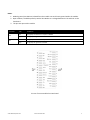
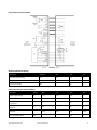
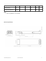
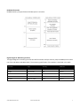
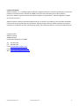
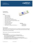
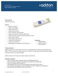
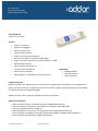
XFP-‐10GE-‐M-‐AO ZTE 10GBASE-‐SR XFP MMF 850NM 300M REACH LC DOM www.addoncomputer.com XFP-‐10GE-‐M-‐AO 10Gbs XFP Transceiver Features • Duplex LC connector • Support hot-‐pluggable • Metal with lower EMI • • • • • Excellent ESD protection VCSEL Transmitter and PIN Receiver Distance up to 300m on 50/125um MMF (OM3) Single 3.3V power supply and Low power dissipation <0.8W GR-‐253-‐CORE compliant • • • • RoHS Compliant and Lead-‐Free Compliant with IEEE 802.3ae Compliant with XFP MSA Digital diagnostic compatible with SFF-‐847 Rev11.0 Applications • 10GBASE-‐SR/SW • 10G Fibre Channel • Other optical link Product Description AddOn Computer’s XFP-‐10GE-‐M-‐AO XFP transceivers are compatible with the XFP Multi-‐Sourcing Agreement (MSA). The XFP transceivers are high performance, cost effective modules supporting dual data-‐rate of 10Gbps and support distance up to 300m with MMF. AddOn Computer’s XFP transceivers are RoHS compliant and lead-‐free Regulatory Compliance • ESD to the Electrical PINs: compatible with MIL-‐STD-‐883E Method 3015.7. • ESD to the Duplex LC Receptacle: compatible with IEC 61000-‐4-‐2 GR-‐1089-‐CORE. • Immunity compatible with IEC 61000-‐4-‐3. • EMI compatible with FCC Part 15 Class B EN55022 Class B (CISPR 22B) VCCI Class B. • Laser Eye Safety compatible with FDA 21CFR 1040.10 and 1040.11 EN60950, EN (IEC) 60825-‐1,2. • RoHS compliant with 2002/95/EC 4.1&4.2 2005/747/EC. www.addoncomputer.com Phone: 877.292.1701 1 Pin Descriptions Pin Symbol Name/Descriptions Ref. 1 GND Module Ground 2 Vee5 (not required) 3 MOD_DESEL 4 /INTERRUPT 5 TX_DIS Transmitter Disable. Logic1 indicates laser output disabled, LVTTL-‐I 6 VCC5 +5V Power Supply (Not required) 3 7 GND Module Ground 1 8 VCC3 +3.3V Power Supply 9 VCC3 +3.3V Power Supply 10 SCL 2-‐Wire Serial Interface Clock. LVTTL-‐I 2 11 SDA 2-‐Wire Serial Interface Data Line. LVTTL-‐I/O 2 12 MOD_Abs Indicates Module is not present. Grounded in the Module. LVTTL-‐O 2 13 MOD_NR Module Not Ready; Indicating Module Operational Fault. Open-‐collector. LVTTL-‐O 2 14 RX_LOS Loss of Signal indication. Logic 1 indicates loss of Signal. Open-‐collector. LVTTL-‐O 2 15 GND Module Ground 1 16 GND Module Ground 1 17 RD-‐ Receiver Inverted Data Output. CML-‐O 18 RD+ Receiver Non-‐Inverted Data Output. CML-‐O 19 GND Module Ground 1 20 VCC2 +1.8V Power Supply (Not required). 3 21 P_DOWN/RST Power down; When high, requires the module to limit power consumption to 1.5W or below. 2-‐Wire serial interface must be functional in the low power mode. LVTTL-‐I Reset; The falling edge initiates a complete reset of the module including the 2-‐ wire serial interface, equivalent to a power cycle. LVTTL-‐I 22 VCC2 +1.8V Power Supply (Not required) 3 23 GND Module Ground 1 24 REFCLK+ Reference Clock (Not required) 25 REFCLK-‐ Reference Clock (Not required) 26 GND Module Ground 1 27 GND Module Ground 1 28 TD-‐ Transmitter Inverted Data Input. CML-‐I 29 TD+ Transmitter Non-‐Inverted Data Input. CML-‐I 30 GND Module Ground 1 www.addoncomputer.com Module De-‐select; When Held low allows the module to respond to 2-‐wire serial interface. LVTTL-‐I Interrupt; Indicates presence of an important condition which can be read via the 2-‐wire serial interface. LVTTL-‐O Phone: 877.292.1701 2 2 Notes: 1. Module ground pins GND are isolated from the module case and chassis ground within the module. 2. Open collector; should be pulled up with 4.7K-‐10Kohms to a voltage between 3.15V and 3.6V on the host board. 3. The pins are open within module. Parameter RS0 RS1 State Conditions Low Rx signally rate less than or equal to 4.25GBd. High Rx signally rate great than 4.25GBd. Low Tx signally rate less than or equal to 4.25GBd. High Tx signally rate great than 4.25GBd. Pin-‐out of connector Block on Host board www.addoncomputer.com Phone: 877.292.1701 3 Recommend Circuit Schematic Absolute Maximum Ratings Parameter Symbol Min. Max. Unit Maximum Supply Voltage Vcc -‐0.5 4.0 V Storage Temperature TS -‐40 85 °C Operating Humidity RH 5 95 % Recommended Operating Conditions Parameter Symbol Min. Typ. Max. Unit Power Supply Voltage Vcc 3.13 3.30 3.47 V Power Supply Current Icc 475 mA Case Operating Temperature – Commercial Tc -‐5 70 °C Case Operating Temperature – Industrial Tc -‐40 85 °C Data Rate 9.95 10.3 10.5 Gbps 50/125µm MMF (OM3) Lmax 300 m www.addoncomputer.com Phone: 877.292.1701 4 Electrical Characteristics Parameter Symbol Min. Typ. Max. Unit Notes Differential data input swing Vin, pp 120 600 850 mV Input differential impedance Zin 90 100 110 Ω TX Disable-‐High 2.0 Vcc+0.3 V TX Disable-‐Low Vee-‐0.3 0.8 V TX Fault-‐High 2.0 Vcc+0.3 V TX Fault-‐Low Vee-‐0.3 0.8 V Differential data output swing Vout, pp 300 600 850 mV Output Differential Impedance Zin 90 100 110 Ω LOS-‐High 2.0 Vcc+0.3 V LOS-‐Low Vee-‐0.3 0.8 V Symbol Min. Typ. Max. Unit Notes Output Opt. Power -‐7.3 -‐1 dBm 1 Optical modulation amplitude P(OMA) -‐4.3 -‐2 dBm Extinction Ratio ER 3 dB Transmitter and Dispersion Penalty TDP 3.9 dB Average Launch power OFF TX Poff -‐30 dBm Optical Wavelength λ 840 860 nm Optical Return Loss Tolerance ORLT 12 dB Relative Intensity Noise RIN -‐128 dB/Hz Transmitter Receiver Optical Characteristics Parameter Transmitter Eye Diagram Compatible with IEEE 802.3-‐2005 Receiver Overload 1 dBm 1 Optical Center Wavelength λC 840 860 nm 1 LOS De-‐Assert LOSD -‐13 dBm 1 LOS Assert LOSA -‐30 dBm www.addoncomputer.com Phone: 877.292.1701 5 LOS Hysteresis 0.5 5 dB Receiver Sensitivity PIN -‐9.9 dBm Receiver Sensitivity @ FEC rate PIN-‐OMA -‐11.1 dBm Notes: 1. BER ≤ 10-‐12@PRBS231-‐1 at 10.3125Gb/s. Mechanical Specifications www.addoncomputer.com Phone: 877.292.1701 6 EEPROM Information EEPROM memory map specific data field description is as below: Digital Diagnostic Monitoring Interface The digital diagnostic monitoring interface also defines another 256-‐byte memory map in EEPROM, which makes use of the 8 bi address 1010001X (A2h). The monitoring specification of this product is described in this table. Parameter Range Accuracy Calibration Temperature -‐5°C to 85°C ±3°C Internal Voltage 2.97V to 3.63V ±3% Internal Bias Current 0mA to 100mA ±10% Internal TX Power -‐7.3dBm to -‐1dBm ±2dB Internal RX Power -‐12dBm to -‐1dBm ±2dB Internal www.addoncomputer.com Phone: 877.292.1701 7 Contact Information AddOn Computer, Inc. is a leading supplier of Memory Upgrade, Network Transceivers and Network connectivity products to Channel Partners, Resellers and OEMs, with more than seventeen years of direct industry experience. AddOn Computer has been the exclusive supplier to Ingram Micro's "Memory Upgrades" program for the past nine years. AddOn Computer maximizes profitable opportunities for our partners. Our ability to source product worldwide, ensures that our pricing will always be competitive. Offering turnkey solutions, AddOn Computer has forged a reputation as a solutions provider, delivering high quality, cost effective product in a timely and reliable manner. Corporate office: AddOn Computer 30400 Esperanza Rancho Santa Margarita, CA 92688 Tel: 877-‐292-‐1701 Fax: 949-‐266-‐9273 Email: [email protected] Email: [email protected] Web: http://www.addoncomputer.com www.addoncomputer.com Phone: 877.292.1701 8