1
Intel® 82599 10 Gigabit Ethernet Controller Specification Update Networking Division (ND) March 2014 Revision 3.1 Intel® 82599 10 GbE Controller—Revision History Revision History Date Revision Description 9/2008 0.5 • Supports datasheet. Initial public release. 11/2008 0.6 • Supports datasheet. Updated with additional testing results. 3/2009 0.75 • Removed fixed Errata #9, #10, #23. 5/20091 1.9 • Added Errata #25 through #38. 1. Revision number changes to 1.9 at product release. No other versions have been released between revisions 0.75 and 1.9. Date Revision 7/2009 2.0 • Initial Public Release. 10/2009 2.1 • Added Specification Clarification #2. 1/2010 • Added Erratum #36. • Updated Erratum#13. • Added Specification Clarification #4. • Added device ID for CX4 and combined backplane. • Added Erratum #37. 3/2011 2.3 • Added Erratum #38, #39, and #40. 9/2010 2.4 • Added Specification Change #1. 10/2010 1/2011 3/2011 2 2.2 Description 2.5 2.6 2.7 • Added Errata #34, #45, and #56. • Added Errata #41,#42,#43, and #44. • Added Specification Clarification #67. • Added Software Clarification #1. • Added Errata #45 and #46. • Added Specification Change #2. • Added Specification Clarification #7 and #8. • Added Errata #47, #48, #49, and #50. • Added Software Clarification #2. • Revised Specification Change #2. • Added Specification Change #3. Revision History—Intel® 82599 10 GbE Controller Date Revision 8/15/2011 2.81 Description Specification Clarifications added or updated: • 6. AN 1G TIMEOUT Only Works When the Link Partner Is Idle (Text in description corrected.) • 8. PCIe Timeout Interrupt (Added) • 9. Master Disable Flow (Added) Errata added or updated: • 48. FCoE: Exhausted Receive Context Is not Invalidated if Last Buffer Size Is Equal to User Buffer Size (Updated Windows* driver information in workaround.) • 50. LED Does not Blink in Invert Mode (Added) • 51. LEDs Cannot Be Configured to Blink in LED_ON Mode (Added) Software Clarifications added or updated: • 9/14/2011 2.82 3. Serial Interfaces Programmed by Bit Banging Device Information added: • JL82599EN (Single Port; SFI Only). Port 1 disabled. See device information tables; for example - Table 1-1. Errata added or updated: 10/28/2011 2.83 • 5. Flow Director Statistics Inaccuracy (Problem statement updated for clarity.) • 52. NC-SI: Get NC-SI Pass-Through Statistics Response Format (Added) Device Information updated: • 12/7/2011 2.84 Specification Clarifications added or updated: • 2/03/2012 2.85 Table 1-1: S-Specification names were incorrect. These have been corrected. 5. SFP+ (SFI) Connection Clarification (Note updated. Reference made to workaround available under NDA.) Specification Clarifications added or updated: 10. Padding on Transmitted SCTP Packets.Errata added or updated: • 37. PCIe: PM_Active_State_NAK Message Might Be Ignored (New internal-only text added to the second workaround bullet: “In this case, if 82599 is connected to a x1 or x2 Lane PCIe Link, it might send a PM_Active_State_Request_L1 DLLP with bad CRC and a Correctable Error will be reported by Upstream Device. See https://vthsd.iil.intel.com/ hsd/hadar/bug_de/default.aspx?bug_de_id=2610409.”) • 4/24/2012 2.86 Specification Clarifications added or updated: • 11. 82599EN EEPROM Image File (Added) Specification Changes added or updated: • 4. Bit 16 of CTRL_EXT Register Must Be Set (Added) Errata added or updated: • 53. Flow Director Filters Configuration Issue (Added) • 54. PF's MSI TLP Might Contain the Wrong Requester ID When a VF Uses MSI-X (Added) Software Clarifications added or updated: • 4. Identify Network Adapter Port by Blinking LED (Added) • 5. PF/VF Drivers Should Configure Registers That Are not Reset by VFLR (Added) 3 Intel® 82599 10 GbE Controller—Revision History Date Revision 9/5/2012 2.87 Description Specification Clarifications added or updated: • 2. PCIe Completion Timeout Value Must Be Properly Set (Last two paragraphs updated for clarity.) Specification Changes added or updated: • 5. MAC Link Setup and Auto Negotiation (Added) Errata added or updated: 6/21/13 2.9 • 55. XAUI Interface Might not Be Able to Link After a Specific Reset Sequence (Added) • 56. ETS Resolution (Added) • 57. Flow Control and Missed Packets Counters Limitation (Added) Specification Clarifications added or updated: • 12. Selecting a RX Pool Using VLAN Filters (Added) • 13. 82599 SFP+ Receiver Specification Conforms to SFF-8431 (Added) • 14. SR-IOV and Jumbo Frames Support in 82599 (Added) Specification Changes added or updated: • 1. PBA Number Module — Word Address 0x15-0x16 • 2. Updates to PXE/iSCSI EEPROM Words (B0 Stepping) • 4. Bit 16 of CTRL_EXT Register Must Be Set • 6. RXMTRL.UDPT Initial Value (Added) • 7. Flow Director Registers Update (Added) • 8. EEPROM Device Size (Added) • 9. The Flow Director FDIRErr(0) Bit in the Rx Descriptor Is Valid Only if the FLM Bit Is Set (Added) Errata added or updated: 1/8/14 3.0 • 5. Flow Director Statistics Inaccuracy • 33. The EEPROM Core Clocks Gate Disable Setting Impacts Link Status During D3 State • 47. PCIe: N_FTS Value Is too Small When Common Clock Configuration Is Zero • 58. 82599 LAN Port #1 SFI Link Instability (Added) • 59. NC-SI: Get NC-SI Pass-through Statistics Response Might Contain Incorrect Packet Counts (Added) • 60. IPv4 Checksum Error Might Be Reported for Multicast Frames Over 12 KB (Added) • 61. RXMEMWRAP Register Content Is Inaccurate (Added) • 62. Flow Director: Collision Indication Can Be Cleared by Adding a New Filter (Added) Specification Clarifications added or updated: • 15. VLAN Anti-spoof Filter of an Untagged Packet (Added) • 16. SR-IOV Prefetchable Address Space (Added) Errata added or updated: • 3/27/14 3.1 Marking Diagram updated: • 4 63. Clearing RXEN During VM-to-VM Loopback Traffic Might Cause Rx Hang (Added) Marking Diagram in Figure 1-1 updated to reflect new substrate. LEGAL—Intel® 82599 10 GbE Controller LEGAL By using this document, in addition to any agreements you have with Intel, you accept the terms set forth below. You may not use or facilitate the use of this document in connection with any infringement or other legal analysis concerning Intel products described herein. You agree to grant Intel a non-exclusive, royalty-free license to any patent claim thereafter drafted which includes subject matter disclosed herein. INFORMATION IN THIS DOCUMENT IS PROVIDED IN CONNECTION WITH INTEL PRODUCTS. NO LICENSE, EXPRESS OR IMPLIED, BY ESTOPPEL OR OTHERWISE, TO ANY INTELLECTUAL PROPERTY RIGHTS IS GRANTED BY THIS DOCUMENT. EXCEPT AS PROVIDED IN INTEL'S TERMS AND CONDITIONS OF SALE FOR SUCH PRODUCTS, INTEL ASSUMES NO LIABILITY WHATSOEVER AND INTEL DISCLAIMS ANY EXPRESS OR IMPLIED WARRANTY, RELATING TO SALE AND/OR USE OF INTEL PRODUCTS INCLUDING LIABILITY OR WARRANTIES RELATING TO FITNESS FOR A PARTICULAR PURPOSE, MERCHANTABILITY, OR INFRINGEMENT OF ANY PATENT, COPYRIGHT OR OTHER INTELLECTUAL PROPERTY RIGHT. A “Mission Critical Application” is any application in which failure of the Intel Product could result, directly or indirectly, in personal injury or death. SHOULD YOU PURCHASE OR USE INTEL'S PRODUCTS FOR ANY SUCH MISSION CRITICAL APPLICATION, YOU SHALL INDEMNIFY AND HOLD INTEL AND ITS SUBSIDIARIES, SUBCONTRACTORS AND AFFILIATES, AND THE DIRECTORS, OFFICERS, AND EMPLOYEES OF EACH, HARMLESS AGAINST ALL CLAIMS COSTS, DAMAGES, AND EXPENSES AND REASONABLE ATTORNEYS' FEES ARISING OUT OF, DIRECTLY OR INDIRECTLY, ANY CLAIM OF PRODUCT LIABILITY, PERSONAL INJURY, OR DEATH ARISING IN ANY WAY OUT OF SUCH MISSION CRITICAL APPLICATION, WHETHER OR NOT INTEL OR ITS SUBCONTRACTOR WAS NEGLIGENT IN THE DESIGN, MANUFACTURE, OR WARNING OF THE INTEL PRODUCT OR ANY OF ITS PARTS. Intel may make changes to specifications and product descriptions at any time, without notice. Designers must not rely on the absence or characteristics of any features or instructions marked “reserved” or “undefined”. Intel reserves these for future definition and shall have no responsibility whatsoever for conflicts or incompatibilities arising from future changes to them. The information here is subject to change without notice. Do not finalize a design with this information. The products described in this document may contain design defects or errors known as errata which may cause the product to deviate from published specifications. Current characterized errata are available on request. Contact your local Intel sales office or your distributor to obtain the latest specifications and before placing your product order.Copies of documents which have an order number and are referenced in this document, or other Intel literature, may be obtained by calling 1-800-548-4725, or go to: http://www.intel.com/design/literature.htm. Intel and Intel logo are trademarks or registered trademarks of Intel Corporation or its subsidiaries in the United States and other countries. *Other names and brands may be claimed as the property of others. Copyright © 2009-2014; Intel Corporation. All Rights Reserved. §§ 5 Intel® 82599 10 GbE Controller—LEGAL NOTE: 6 This page intentionally left blank. Introduction—Intel® 82599 10 GbE Controller 1.0 Introduction This document applies to the Intel® 82599 10 GbE Controller. This document is an update to the Intel® 82599 10 Gigabit Ethernet Controller Datasheet. It is intended for use by system manufacturers and software developers. All product documents are subject to frequent revision and new order numbers will apply. New documents may be added. Be sure you have the latest information before finalizing your design. References to PCI Express* (PCIe*) in this document refer to PCIe V2.0 (2.5GT/s or 5.0GT/s). 1.1 Product Code and Device Identification Product Code: JL8259EB, JL82599ES, JL82599EN (lead free). The following tables and drawings describe the various identifying markings on each device package: Table 1-1 Markings Device Stepping Top Marking S-Specification1 Description B0 JL82599EB SLGWG Production (Lead Free) 82599 (Performance; XAUI) SLGWH 82599 (Performance; XAUI + Serial; KR/SFI) B0 82599EN (Single Port SFI Only); Port 1 disabled. B0 JL82599ES SLGWE Production (Lead Free) SLGWF JL82599EN SLJFT Production (Lead Free) SLJFU 1. For Tray, Tape, Reel data (see Table 1-3). Table 1-2 Device ID Device ID Code Vendor ID Device ID 82599 (KX/KX4) 0x8086 0x10F7 82599 (combined backplane; KR/KX4/KX) 0x8086 0x10F8 82599 (CX4) 0x8086 0x10F9 82599 (SFI/SFP+) 0x8086 0x10FB 7 Intel® 82599 10 GbE Controller—Marking Diagram Table 1-2 Device ID (Continued) Device ID Code Vendor ID Device ID 82599 (XAUI/BX4) 0x8086 0x10FC 82599 (Single Port SFI Only) 0x8086 0x1557 1.2 Marking Diagram Table 1-3 MM Numbers Product Tray MM# Tape and Reel MM# JL82599 (Lead Free) B0 Production (Performance; XAUI) 903143 903142 JL82599 (Lead Free) B0 Production (Performance; XAUI + Serial; KR/SFI) 903140 903139 JL82599EN (Single Port SFI Only); Port 1 disabled. B0 Production 917842 917841 Figure 1-1 Example with Identifying Marks Lead-free parts will have “JL” as the prefix for the product code . The “S” designator refers to the specification number. See Table 1-1. Devices can also have a “GB” marking, instead of “EB or ES”. These are functionally equivalent and only used on Intel network interface adapters. 8 Nomenclature Used in This Document—Intel® 82599 10 GbE Controller 1.3 Nomenclature Used in This Document This document uses specific terms, codes, and abbreviations to describe changes, errata, sightings and/or clarifications that apply to silicon/steppings. See Table 1-4 for a description. Table 1-4 Terms, Codes, Abbreviations Name Description Specification Changes Modifications to the current published specifications. These changes will be incorporated in the next release of the specifications. Errata Design defects or errors. Errata may cause device behavior to deviate from published specifications. Hardware and software designed to be used with any given stepping must assume that all errata documented for that stepping are present on all devices. Sightings Observed issues that are believed to be errata, but have not been completely confirmed or root caused. The intention of documenting sightings is to proactively inform users of behaviors or issues that have been observed. Sightings may evolve to errata or may be removed as non-issues after investigation completes. Specification Clarifications Greater detail or further highlights concerning a specification’s impact to a complex design situation. These clarifications will be incorporated in the next release of the specifications. Documentation Corrections Errors, or omissions in current published specifications. These changes are incorporated in the next release of the applicable document and then dropped from the specupdate. Check for a complete list of changes in revision history of specific documents. Software Clarifications Applies to Intel drivers, EEPROM loads. Yes or No If the errata applies to a stepping, “Yes” is indicated for the stepping (for example: “A0=Yes” indicates errata applies to stepping A0). If the errata does not apply to stepping, “No” is indicated (for example: “A0=No” indicates the errata does not apply to stepping A0). Doc Document change or update that will be implemented. Fix This erratum is intended to be fixed in a future stepping of the component. Fixed This erratum has been previously fixed. NoFix There are no plans to fix this erratum. Eval Plans to fix this erratum are under evaluation. (No mark) or (Blank box) This erratum is fixed in listed stepping or specification change does not apply to listed stepping. Red Change Bar/ or Bold This Item is either new or modified from the previous version of the document. DS Data Sheet AP Application Note 9 Intel® 82599 10 GbE Controller—Hardware Sightings, Clarifications, Changes, Updates, and Errata 2.0 Hardware Sightings, Clarifications, Changes, Updates, and Errata See Section 1.3 for an explanation of terms, codes, and abbreviations. Table 2-1 Summary of Hardware Sightings Hardware Sighting None Table 2-2 N/A Summary of Specification Clarifications Specification Clarification 10 Status Status 1. SFP+ Statement N/A 2. PCIe Completion Timeout Value Must Be Properly Set N/A 3. NC-SI Set Link Command Support N/A 4. Use of Wake on LAN Together with Manageability N/A 5. SFP+ (SFI) Connection Clarification N/A 6. AN 1G TIMEOUT Only Works When the Link Partner Is Idle N/A 7. Link Establishment State Machine (LESM) N/A 8. PCIe Timeout Interrupt N/A 9. Master Disable Flow N/A 10. Padding on Transmitted SCTP Packets N/A 11. 82599EN EEPROM Image File N/A 12. Selecting a RX Pool Using VLAN Filters N/A 13. 82599 SFP+ Receiver Specification Conforms to SFF-8431 N/A 14. SR-IOV and Jumbo Frames Support in 82599 N/A 15. VLAN Anti-spoof Filter of an Untagged Packet N/A Hardware Sightings, Clarifications, Changes, Updates, and Errata—Intel® 82599 10 GbE Controller Table 2-2 Summary of Specification Clarifications (Continued) Specification Clarification 16. SR-IOV Prefetchable Address Space Table 2-3 Status N/A Summary of Specification Changes Specification Change Status 1. PBA Number Module — Word Address 0x15-0x16 N/A 2. Updates to PXE/iSCSI EEPROM Words (B0 Stepping) N/A 3. Flow Director: Update Filter Flow Limitation N/A 4. Bit 16 of CTRL_EXT Register Must Be Set N/A 5. MAC Link Setup and Auto Negotiation N/A 6. RXMTRL.UDPT Initial Value N/A 7. Flow Director Registers Update N/A 8. EEPROM Device Size N/A 9. The Flow Director FDIRErr(0) Bit in the Rx Descriptor Is Valid Only if the FLM Bit Is Set N/A Table 2-4 Summary of Documentation Changes Documentation Change None. Table 2-5 Status N/A Summary of Errata; Errata Include Steppings Erratum Status 1. Cause of Interrupt Might Never Be Cleared B0=Yes; NoFix 2. Flow Director: Length-Error Bit not Updated on Remove Operation B0=Yes; NoFix 3. Flow Director: Filter Might Lose Length-Error Attribute in Perfect-Match Mode B0=Yes; NoFix 4. Flow Director: L4Packet Type Might Give Wrong Indication B0=Yes; NoFix 5. Flow Director Statistics Inaccuracy B0=Yes; NoFix 6. No Length Error on VLAN Packets with Bad Type/Length Field B0=Yes; NoFix 7. GPRC and GORCL/H Also Count Missed Packets B0=Yes; NoFix 11 Intel® 82599 10 GbE Controller—Hardware Sightings, Clarifications, Changes, Updates, and Errata Table 2-5 Summary of Errata; Errata Include Steppings (Continued) Erratum 12 Status 8. Incorrect Behavior in the Switch Security Violation Packet Count (SSVPC) Statistic Register B0=Yes; NoFix 9. FCoE: To Read DMA-Rx FCoE context, CSRs Need to Add a Dummy Write B0=Yes; NoFix 10. In 100M Link Mode, CSR Access to DMA-Rx Might Reach Internal Timeout B0=Yes; NoFix 11. MACSec: When PN=0, Packet Is not Dropped B0=Yes; NoFix 12. MACSec: LSECRXUC, LSECRXNUSA and LSECRXUNSA Statistics Counters not Implemented According to Specification B0=Yes; NoFix 13. Issues in Clock Switching of MAC Clocks B0=Yes; NoFix 14. FEC: Correctable and Uncorrectable Counter Read Mechanism Is Malformed B0=Yes; NoFix 15. Clause 37 AN: 82599 Will not Restart AN if Receiving Invalid Idle Codes During Configuration State B0=Yes; NoFix 16. Doesn't Meet the Timing Requirements for PAUSE Operation at 1G Speed B0=Yes; NoFix 17. Device Doesn't Meet the Timing Requirements for PAUSE Operation at 100 MB Speed B0=Yes; NoFix 18. SGMII 100M: 82599 Might Need a SW-Reset When Link-Mode Enters/Exits 100M B0=Yes; NoFix 19. DFT: Rx-to-Tx Loopback (XGMII LPBK) in 1Gb\100Mb with Low IPG May Cause Chopped Packet B0=Yes; NoFix 20. DFT: JTDO Output Is Disabled During HIGHZ Instruction B0=Yes; NoFix 21. MACSec: Tx Octets Protected (LSECTXOCTP) Increment More Than Required B0=Yes; NoFix 22. The 82599 Might Reach Block-Lock After 63 Sync_Headers Instead of 64 B0=Yes; NoFix 23. ERR_COR Message TLPs Are not Sent for Advisory Errors in D3 B0=Yes; NoFix 24. PCIe Bandwidth in Non-Optimal Gen1 2.5GT/s Conditions Might Be Limited in Single Port Configuration B0=Yes; NoFix 25. Bus Number and Device Number Are not Preserved Through PCIe Reset B0=Yes; NoFix 26. 82599 Might not Be Recognized by PCIe in EEPROM-Less Mode B0=Yes; NoFix 27. Device Might Fail to Establish Link When Multiple Link Numbers Are Advertised by the Upstream Device B0=Yes; NoFix 28. Re-Enabling a Port Using the Rising Edge of LAN_DIS_N Requires a LAN_PWR_GOOD Reset B0=Yes; NoFix 29. BMC Receives Non-MACSec Packets from the LAN Without an Indication Regarding to Received Packet Type (With/Without MACSec Header) B0=Yes; NoFix Hardware Sightings, Clarifications, Changes, Updates, and Errata—Intel® 82599 10 GbE Controller Table 2-5 Summary of Errata; Errata Include Steppings (Continued) Erratum Status 30. NC-SI: Additional Multicast Packets May Be Forwarded to the BMC B0=Yes; NoFix 31. SMBus: Unread Packets Received on One Port May Cause Loss of Ability to Receive on Other Port B0=Yes; NoFix 32. NC-SI: Packet Loss When the BMC Sends Packets to Both Ports and One Port Has Its Link Down B0=Yes; NoFix 33. The EEPROM Core Clocks Gate Disable Setting Impacts Link Status During D3 State B0=Yes; NoFix 34. Priority Flow Control (PFC) to Some Traffic Classes (TCs) Might Impact Traffic on Other Traffic Classes B0=Yes; NoFix 35. SR-IOV: PCIe Capability Structure in VF Area Is Incorrectly Implemented B0=Yes; NoFix 36. SR-IOV: Incorrect Completer ID for Config-Space Transactions B0=Yes; NoFix 37. PCIe: PM_Active_State_NAK Message Might Be Ignored B0=Yes; NoFix 38. PCIe: Incorrect PCIe De-emphasis Level Might Be Reported B0=Yes; NoFix 39. APM Wake-Up Might Be Blocked if System Is Shutdown Before Driver Load B0=Yes; NoFix 40. PME_Status Might Fail to Report a Wake-Up Event B0=Yes; NoFix 41. DMA: QBRC and VFGORC Counters Might Get Corrupted if Receiving a Packet Bigger Than 12 KB B0=Yes; NoFix 42. PCIe: 82599 Transmitter Does not Enter L0s B0=Yes; NoFix 43. Integrity Error Reported for IPv4/UDP Packets with Zero Checksum B0=Yes; NoFix 44. Header Splitting Can Cause Unpredictable Behavior B0=Yes; NoFix 45. PCIe Compliance Pattern Is not Transmitted When Connected to a x4/x2/x1 Slot B0=Yes; NoFix 46. PCIe: Correctable Errors Reported When Using Rx L0s in a x1 Configuration B0=Yes; NoFix 47. PCIe: N_FTS Value Is too Small When Common Clock Configuration Is Zero B0=Yes; NoFix 48. FCoE: Exhausted Receive Context Is not Invalidated if Last Buffer Size Is Equal to User Buffer Size B0=Yes; NoFix 49. KR TXFFE Coefficient Update Is not Possible if Middle Coefficient Is at Maximum Value B0=Yes; NoFix. 50. LED Does not Blink in Invert Mode B0=Yes; NoFix 51. LEDs Cannot Be Configured to Blink in LED_ON Mode B0=Yes; NoFix 52. NC-SI: Get NC-SI Pass-Through Statistics Response Format B0=Yes; NoFix 13 Intel® 82599 10 GbE Controller—Hardware Sightings, Clarifications, Changes, Updates, and Errata Table 2-5 Summary of Errata; Errata Include Steppings (Continued) Erratum 14 Status 53. Flow Director Filters Configuration Issue B0=Yes; NoFix 54. PF's MSI TLP Might Contain the Wrong Requester ID When a VF Uses MSI-X B0=Yes; NoFix 55. XAUI Interface Might not Be Able to Link After a Specific Reset Sequence B0=Yes; NoFix 56. ETS Resolution B0=Yes; NoFix 57. Flow Control and Missed Packets Counters Limitation B0=Yes; NoFix 58. 82599 LAN Port #1 SFI Link Instability B0=Yes; NoFix 59. NC-SI: Get NC-SI Pass-through Statistics Response Might Contain Incorrect Packet Counts B0=Yes; NoFix 60. IPv4 Checksum Error Might Be Reported for Multicast Frames Over 12 KB B0=Yes; NoFix 61. RXMEMWRAP Register Content Is Inaccurate B0=Yes; NoFix 62. Flow Director: Collision Indication Can Be Cleared by Adding a New Filter B0=Yes; NoFix 63. Clearing RXEN During VM-to-VM Loopback Traffic Might Cause Rx Hang B0=Yes; NoFix Specification Clarifications—Intel® 82599 10 GbE Controller 2.1 Specification Clarifications 1 SFP+ Statement It is important to note that the SFP+ Specification (SFF-8431) is a system level specification and performance varies as a function of a board design and connector vendor. When designing a system to meet this specification, it is important to take these system level functions into account. The performance measured for the 82599 was captured in a board design as described in the Design Considerations section of the Intel® 82599 10 Gigabit Ethernet Controller Datasheet. Reference this material for detail. 2 PCIe Completion Timeout Value Must Be Properly Set The 82599 Completion Timeout Value[3:0] must be properly set by the system BIOS in the PCIe Configuration Space Device Control 2 register (0xC8; W). Failure to do so can cause unexpected completion timeouts. The 82599 complies with the PCIe 2.0 specification for the completion timeout mechanism and programmable timeout values. The PCIe 2.0 specification provides programmable timeout ranges between 50s to 64s with a default time range of 50s - 50ms. The 82599 defaults to a range of 16 ms – 32 ms. The completion timeout value must be programmed correctly in PCIe configuration space (in Device Control 2 register); the value must be set above the expected maximum latency for completions. This ensures that the 82599 receives completions for the requests it sends out. Failure to properly set the completion timeout value can result in the device timing out prior to a completion returning. The 82599 can be programmed to resend a completion request after a completion timeout (the original completion is assumed lost). But if the original completion arrives after a resend request, two completions may arrive for the same request; this can cause unpredictable behavior. Intel EEPROM images set the resend feature to off. Intel recommends that you do not change this setting. For details on completion timeout operation, refer to the Datasheet. 3 NC-SI Set Link Command Support The NC-SI Set Link command is used to configure the LAN interface with specific provided settings. The settings include link speed, duplex, pause capability, and other vendor specified settings. The command fields have enough flexibility to configure a 10/100/1000 Mb/s LAN port, but the support for 10 GbE is not fully defined in the NC-SI specification. Different 10 GbE options as defined by LMS, 10G_PMA_PMD_PARALLEL and KR_support fields of the AUTOC register cannot be defined by the NC-SI Set Link command. Due to this limitation, the 82599 LAN ports cannot be configured by the NC-SI Set Link command. 15 Intel® 82599 10 GbE Controller—Specification Clarifications 4 Use of Wake on LAN Together with Manageability The Wakeup Filter Control Register (WUFC) contains the NoTCO bit, which affects the behavior of the wakeup functionality when manageability is in use. Note that if manageability is not enabled, the value of NoTCO has no effect. When NoTCO contains the hardware default value of 0b, any received packet that matches the wakeup filters will wake the system. This could cause unintended wakeups in certain situations. For example, if Directed Exact Wakeup is used and the manageability shares the host's MAC address, IPMI packets that are intended for the BMC wakes the system, which might not be the intended behavior. When NoTCO is set to 1b, any packet that passes the manageability filter, even if it also is copied to the host, is excluded from the wakeup logic. This solves the previous problem since IPMI packets do not wake the system. However, with NoTCO=1b, broadcast packets, including broadcast magic packets, do not wake the system since they pass the manageability filters and are therefore excluded. Table 2-6 Effects of NoTCO Settings WoL Share MAC Address NoTCO Unicast packet Broadcast Packet Magic Packet 0b N/A OK OK Magic Packet 1b Y No wake No wake. Magic Packet 1b N OK No wake. Y Wake even if MNG packet. No way to talk to the BMC without waking host. N/A Directed Exact 0b Directed Exact 0b N OK N/A Directed Exact 1b N/A OK N/A Note: 5 Intel Windows* drivers set NoTCO by default. SFP+ (SFI) Connection Clarification The 82599 configuration is optimized to set link with an external partner. If the two ports of the 82599 are connected back-to-back in SFP+ (SFI) mode, link might fail to establish. Similarly, if transmit and receive are connected together within the same port in SFP+ (SFI) mode, link might fail to establish. This does not impact end users. This configuration would typically be encountered in a manufacturing or test environment to verify link establishment and perform basic functionality checks. In this environment, Intel recommends the use of a separate standalone link partner. Note: 16 There is a document that discusses the workaround for special cases. This document is available under NDA. Contact your Intel representative for access. Specification Clarifications—Intel® 82599 10 GbE Controller 6 AN 1G TIMEOUT Only Works When the Link Partner Is Idle The auto-negotiation timeout mechanism (PCS1GLCTL.AN_1G_TIMEOUT_EN) only works if the 1G partner is sending idle code groups continuously for the duration of the timeout period, which is the usual case. However, if the partner is transmitting packets, an auto-negotiation timeout will not occur since auto-negotiation is restarted at the beginning of each packet. If the partner has an application that indefinitely transmits data despite the lack of any response, it is possible that a link will not be established. If this is a concern, the auto-negotiation timeout mechanism may be considered unreliable and an additional software mechanism could be used to disable auto-negotiation if sync is maintained without a link being established (PCS1GLSTA.SYNC_OK_1G=1b and LINKS.LINK_UP=0b) for an extended period of time. 7 Link Establishment State Machine (LESM) “Legacy” XAUI-based switches developed prior to the IEEE 802.3ap standard will Tx only in one lane (Lane 0) during link detection. Typically, these devices will only transition to a XAUI-like 10 GbE link when all 4 pairs of their receivers are active. Additionally, IEEE 802.3ap compliant devices such as the 82599 controller are required to transmit auto-neg only on Lane 0 per Clause 73.3 and the Intel device will also only parallel-detect a XAUI-like 10 GbE link when all 4 pairs of their receivers are active. Therefore, a speedlock condition can occur when the 82599 device is connected to a legacy XAUI-based switch since both devices are capable of 10 GbE XAUI-like parallel detection but only the lane 0 transmitters on each device are active. One device needs to turn on all 4 transmitters in order for the other device to see 10 GbE XAUI-like mode; otherwise, either no link or a 1 GbE link is observed in the system, depending on the specific behavior of the switch link state machine. LESM was developed by Intel to break the speedlock condition described above. The feature can be implemented in the 82599 controller with on-chip firmware and is used to switch the link-mode-select setting in the AUTOC register to try a different configuration after timeout. For example, after trying CL 73 AN and Parallel Detect, it might change to XAUI-mode (which turns on all 4 lane transmitters) and check link status. If you are experiencing link issues with the 82599 when configured to Backplane Auto Negotiation and connected to a XAUI-based switch, please contact your Intel representative to get an EEPROM file with LESM enabled. 8 PCIe Timeout Interrupt The PCIe Timeout Exception (TO) bit in the PCIe Interrupt Cause (PICAUSE) register is set when a timeout occurs on an access to the address space of this port. This includes accesses initiated by the EEPROM auto-load function and manageability firmware, in addition to accesses from the PCIe interface. This interrupt bit does not necessarily indicate a problem with a PCIe transaction and further analysis would be required to determine the source of the problem. 17 Intel® 82599 10 GbE Controller—Specification Clarifications 9 Master Disable Flow During the “Master Disable” flow, the device driver should set the PCIe Master Disable bit and then poll the PCIe Master Enable Status bit to determine if any requests are pending. There are cases where this bit will not be released (such as flow control or link down), even if the PCIe Transaction Pending bit is cleared in the Device Status register. In such cases, the recommendation (see Datasheet, search for “Master Disable”) is to issue two consecutive software resets with a delay larger than 1 microsecond between them. The data path must be flushed before a software resets the 82599. The recommended method to flush the transmit data path is: 1. Inhibit data transmission by setting the HLREG0.LPBK bit and clearing the RXCTRL.RXEN bit. This configuration avoids transmission even if flow control or link down events are resumed. 2. Set the GCR_EXT.Buffers_Clear_Func bit for 20 microseconds to flush internal buffers. 3. Clear the HLREG0.LPBK bit and the GCR_EXT.Buffers_Clear_Func. 4. It is now safe to issue a software reset. 10 Padding on Transmitted SCTP Packets When using the 82599 to offload the CRC calculation for transmitted SCTP packets, software should not add Ethernet padding bytes to short packets (less than 64 bytes). Instead, the HLREG0.TXPADEN bit should be set so that the 82599 pads packets after performing the CRC calculation. 11 82599EN EEPROM Image File The 82599EN SKU (the single-port variant of the product) requires the usage of Dev_Starter EEPROM v4.21 or higher. Please contact your Intel representative to obtain updated EEPROM images. 12 Selecting a RX Pool Using VLAN Filters RX Pool selection is described in 82599 Datasheet, Section 7.10.3.2. Note that pools are first selected by MAC Address filtering, and then by VLAN filtering. If the application is aiming to map packets to pools exclusively by their VLAN tags, it needs to replicate all incoming packets to all the different pools by their MAC Address. In order to achieve the packet replication, PFVTCTL. Rpl_En should be set and the relevant MAC Address filtering bits should be set: • MPSAR, PFUTA, MTA and VFTA tables. • Relevant bits in PFVML2FLT registers – ROMPE, ROPE, BAM and MPE. Pool selection by VLAN is then controlled by the PFVLVF and PFVLVFB registers. 18 Specification Clarifications—Intel® 82599 10 GbE Controller 13 82599 SFP+ Receiver Specification Conforms to SFF-8431 The 82599 SFI interface supports the electrical specification defined in the SFI+ MSA (SFF Committee SFF-8431). The 82599 SFI receiver is conformant with the SFI receiver specification, and expects the transmitted signal to comply with the SFF-8431 electrical specification listed in SFF-8431 3.51 Table 11 and Table 12. Establishing an SFI link with a link partner whose transmitter is non-conformant with this specification might result in link issues, such as link instability and/or Bit Error Rate (BER) failures. If link issues are observed, it might be due to violations of the Eye Mask electrical specifications in Table 12 by the link partner of the 82599. In this case, Intel recommends tuning the Link Partner’s SFI Transmitter signal to be within the range allowed in the SFF-8431 specification. If the Link Partner's SFI Transmitter is not tunable and exceeds the amplitude specification, Intel recommends the use of a lossier medium (such as a longer Direct Attach cable) to provide additional attenuation and thereby attempt to provide a recoverable signal to the 82599 receiver. 14 SR-IOV and Jumbo Frames Support in 82599 To enable Jumbo Frame support with SR-IOV enabled, the Physical Function (PF) and the Virtual Function (VF) must be configured to the same maximum frame size. Additionally, the jumbo frame has a maximum size of 9 KB. Software drivers requiring support for Jumbo Frames in SR-IOV must account for this. SR-IOV and Jumbo Frames are supported in the 82599 on both Linux and Microsoft Windows Server operating systems with Intel software drivers. • Linux Support: Support started with PF (ixgbe 3.15.1) and VF (ixgbevf 2.8.7) drivers available from Intel’s Open Source Driver site (http://sourceforge.net/projects/e1000/files/) and the Linux kernel version 3.2 or newer. • Microsoft Windows Server Support: Supported with Microsoft Windows Server 2012 family starting with Intel Driver Release 18.3 available at http://support.intel.com. 15 VLAN Anti-spoof Filter of an Untagged Packet The VLAN anti-spoofing capability insures that a VM always uses a VLAN tag that is part of the set of VLAN tags defined on the Rx path. A Tx packet with a non-matching VLAN tag is dropped, preventing spoofing of the VLAN tag. Note: 16 An untagged packet is dropped. SR-IOV Prefetchable Address Space In SR-IOV mode, memory space should be allocated to the multiple VFs enabled. To accommodate the full extent of possible memory allocation, 64-bit addressing should be used. The PCI bridge specification requires that a 64-bit BAR be prefetchable. The “prefetchable” bit at IOV Control Word has been set in the NVM Dev Starter releases since Revision 3.13. To obtain an updated EEPROM image, please contact your Intel representative. 19 Intel® 82599 10 GbE Controller—Specification Changes 2.2 Specification Changes 1 PBA Number Module — Word Address 0x15-0x16 Note: 2 Note: 3 This information now appears in the Intel® 82599 10 GbE Controller Datasheet, Revision 2.8 Updates to PXE/iSCSI EEPROM Words (B0 Stepping) This information now appears in the Intel® 82599 10 GbE Controller Datasheet, Revision 2.8 Flow Director: Update Filter Flow Limitation Parameters update of an existing Flow Director filter can be done by the Update Filter Flow as described in the Datasheet. It should be noted that the Update Filter Flow process requires internal memory space used to store temporary data until the update concludes. Therefore, Update Filter Flow can be used only if the maximum number of allocated flow director filters (as defined by FDIRCTRL.PBALLOC) is not fully used. For example, if FDIRCTRL.PBALLOC=01b, memory is allocated for 2K-1 perfect filters. In this case, the Update Filter Flow can be used only if not more than 2K-2 filters were programmed. 4 Note: 20 Bit 16 of CTRL_EXT Register Must Be Set This information now appears in the Intel® 82599 10 GbE Controller Datasheet, Revision 2.8 Specification Changes—Intel® 82599 10 GbE Controller 5 MAC Link Setup and Auto Negotiation According to the 82599 Datasheet (see Section 3.7.4.2), Link is configured by setting the speed in the AUTOC.LMS field, selecting the appropriate physical interface in AUTOC.1G_PMA_PMD, AUTOC.10G_PMA_PMD_PARALLEL, and AUTOC2.10G_PMA_PMD_Serial and is completed by restarting auto-negotiation by setting AUTOC.Restart_AN to 1b. Note that auto-negotiation logic will reset the data pipeline on Restart_AN assertion only if LMS mode is changed. If the user wants to change link configuration parameters with the same AUTOC.LMS field value, link configuration should take these steps: 1. Read AUTOC register. Write back AUTOC register content with LMS[2] bit inverted (AUTOC bit 15) and Restart_AN bit asserted. 2. Read ANAS field in ANLP1 register. Check that it is not zero (or idle), indicating that autonegotiation was restarted. 3. Write AUTOC register with original LMS field and Restart_AN bit asserted. If the LESM feature is enabled (see Specification Clarification #8), the 82599 Device Firmware may access AUTOC register in parallel to software driver and a synchronization between them is needed (described in Datasheet Section 10.5.4). To check that the LESM feature is enabled, note that Word Offset 0x2 of NVM FW Module will not be 0x0000 or 0xFFFF. Note: Failure to follow this sequence can result in unpredictable link issues, including failure to establish link. Intel Drivers follow this updated sequence starting with Release 17.4. 6 RXMTRL.UDPT Initial Value If the Time Sync (IEEE 1588) feature is used, the RXMTRL.UDPT field should be initialized to 0x13F. This is fixed in ixgbe v3.11.20. 7 Flow Director Registers Update • Flow Director Filters Free - FDIRFREE (0x0000EE38) - Bits 30:16 - Reserved • Flow Director Filters Length - FDIRLEN (0x0000EE4C) - Bits 30:16 - Reserved • Flow Director Filters Failed Usage Statistics - FDIRFSTAT (0x0000EE54) - Bits 7:0 - FADD field definition Number of filters addition events that do not change the number of free (non programmed) filters in the flow director filters logic (FDIRFREE.FREE). These events can be either filters update, filters collision, or tentative of filter additions when there is no sufficient space remaining in the filter table. 21 Intel® 82599 10 GbE Controller—Documentation Updates 8 EEPROM Device Size The following EEPROM device size updates will be included in the next Datasheet release. Section 12.6.2.1 - Minimum EEPROM Sizes • No manageability - 16 KB (128 Kb) • SMBus/NC-SI - 32 KB (256 Kb) Section 12.6.2.2 - Recommended EEPROM Sizes • No manageability - 32 KB (256 Kb) • SMBus/NC-SI - 32 KB (256 Kb) Note: 9 These EEPROM device sizes are required when using dev_starter image v4.25 or later. The Flow Director FDIRErr(0) Bit in the Rx Descriptor Is Valid Only if the FLM Bit Is Set The FDIRErr(0) bit in Rx descriptor (length error) is valid only if the FLM bit is set (a packet matches a flow director filter) in the Extended Status of the Advanced Receive Descriptor. 2.3 None. 22 Documentation Updates Errata—Intel® 82599 10 GbE Controller 2.4 Note: 1 Errata If the errata applies to a stepping, “Yes” is indicated for the stepping (for example: “B0=Yes” indicates errata applies to stepping B0). If the errata does not apply to the stepping, “No” is indicated (for example: “B0=No” indicates the errata does not apply to stepping B0). Cause of Interrupt Might Never Be Cleared Problem: If the cause of an interrupt is set by the Extended Interrupt Cause Set (EICS) register writing just before the interrupt line is set, then it might not be cleared. This means that there might be a deadlock that prevents the interrupt line from rising. This erratum only occurs when all three modes referenced are used at the same time: non-PBA mode, Auto Clear (of the cause), No Auto Mask. PBA is Pending Bit Array mode. During this mode the device is able to capture additional interrupts during the interval between initial interrupt and driver access to the device. Implication: The device stops issuing interrupts. Workaround: When operating using the above configurations, software should manually clear the cause by writing a 1b to the specific bit in the relevant EICR/EICR1/EICR2/VTEICR0-63 register (after the interrupt occurs and the EICS was written). This workaround is included in Intel drivers. Status: B0=Yes; NoFix 2 Flow Director: Length-Error Bit not Updated on Remove Operation Problem: In order to avoid high latency, the length of the Flow Director (FD) filters linked list is limited. The length limit is programmable (FDIRCTRL.Max-Length field). If a linked list exceeds this limit, a length error is reported in the FDIRErr.length field in the Rx descriptor. This erratum exists because once a filter is assigned to have the length-error attribute, it stays with this attribute even if an error condition doesn't exist anymore (such as a previous filter was removed from the list). Implication: When the FD table is programmed with many filters while dynamic filter removal is used, the driver might get an indication for over length lists (FDIRErr.length) even though the linked lists are not too long. This indication could be used by the software driver to remove filters from the table. Note that the current software driver does not use the dynamic filter removal option. 23 Intel® 82599 10 GbE Controller—Errata Workaround: Software - Reset Flow Director (FD) tables when max-length indication is observed, or hold image of all the FD table and update the FD table (holding the image is less recommended). The FD table is the hardware internal memory structure. Clearing this table means that the packet buffer memory of FD is cleared and linked to the empty link-list and head/tail CSRs are initialized. All other CSR are re-configured by software (see Datasheet) Status: B0=Yes; NoFix 3 Flow Director: Filter Might Lose Length-Error Attribute in Perfect-Match Mode Problem: In order to avoid high latency, the length of the Flow Director (FD) filters linked list is limited. The length limit is programmable (FDIRCTRL.Max-Length field). If a linked list exceeds this limit, a length error is reported in the FDIRErr.length field in the Rx descriptor. In some rare cases a filter that has the length-error attribute might change the attribute to No-LengthError. As a result, the FD table includes long lists, which are not reported to software. Once a packet matches these filters it causes a slightly higher latency in the device. Implication: There is no expected impact. In the cases where this indication is important, we expect other filters to indicate length-error. FD tables are reset, which lowers the probability of reaching this case.There is also no impact to packet counters. Workaround: None. Status: B0=Yes; NoFix 4 Flow Director: L4Packet Type Might Give Wrong Indication Problem: The MSB of the L4 Packet Type (L4TYPE) field in the Flow Director Filters Command Register (FDIRMC[6]) might give a wrong value during read access. The flow director filters operate with the correct parameters. Implication: No impact on functionality. Software should ignore the read result of this bit. Workaround: None. Make sure that in a read to verify successful write, this bit is ignored. Status: B0=Yes; NoFix 24 Errata—Intel® 82599 10 GbE Controller 5 Flow Director Statistics Inaccuracy Problem: FDIRMATCH should count the number of packets that matched any flow director filter. FDIRMISS should count the number of packets that missed matching any flow director filter. Implication: The counters cannot be used for exact statistics. Counters should be used as an approximate indication on miss/match of filters. Workaround: None. Status: B0=Yes; NoFix 6 No Length Error on VLAN Packets with Bad Type/ Length Field Problem: Device will not assert length error for VLAN packets that have a bad type/length field in the MAC header. Implication: No impact on system level performance. The packets are posted to the host as any other packets. Workaround: None. Status: B0=Yes; NoFix 7 GPRC and GORCL/H Also Count Missed Packets Problem: GPRC (Good Packets Received Count) and GORCL/H (Good Octets Received Count) count missed packets and missed packets bytes; this is not consistent with previous products. Implication: None. Workaround: Statistics are available indirectly for these registers. This workaround is included in Intel drivers. • For GPRC — Subtract MPC (Missed Packet Count) from GPRC. Alternatively, use QPRC. • For GORCL/H — use QBRCL/H (Quad Bytes Received). Status: B0=Yes; NoFix 25 Intel® 82599 10 GbE Controller—Errata 8 Incorrect Behavior in the Switch Security Violation Packet Count (SSVPC) Statistic Register Problem: During VM Migration (or other VFLR scenarios), VM-to-VM packets that should be forwarded to a VM that is currently in migration might be dropped; they may not forwarded to the VM internally and not forwarded to the network. These packets are counted both as bad packets in the SSVPC counter and also as good packets in the DMA-TX good-packet counter. Implication: The statistic is not reliable for VFLR cases. Workaround: None. Status: B0=Yes; NoFix 9 FCoE: To Read DMA-Rx FCoE context, CSRs Need to Add a Dummy Write Problem: There is a need to add a dummy write before the read of an FCoE context CSRs (FCDMARW) to avoid context corruption. Implication: No impact. Workaround: Write FCDMARW twice while having the required FCoE read index valid and '0’ in the RE and WE bits. Status: B0=Yes; NoFix 10 In 100M Link Mode, CSR Access to DMA-Rx Might Reach Internal Timeout Problem: In 100 Mb/s link mode, internal clocks are slower, and access of an internal register can lead to timeout. Implication: An unknown value will be returned on PCIe interface. 26 Errata—Intel® 82599 10 GbE Controller Workaround: SW - in 100 Mb/s link mode we need to disable aggregation in DMA-Rx (set RDRXCTL.AGGDIS=1) and to extend the PCIe timeout extension to 32 µs (set PCIEMISC. TO_extension to 011). When aggregation is disabled, expect an impact on performance for packets below 128B in length. Do not increase the timeout extension beyond 32µs to avoid system issues. Status: B0=Yes; NoFix 11 MACSec: When PN=0, Packet Is not Dropped Problem: According to the MACSec specification, frames with PN=0 (packet number) in the sectag should be counted as bad tags/packets. The 82599 will consider these packets as late packets and they will be incorrectly identified as a late packets instead of a bad tag/packets. So they are dropped, but for the wrong reason (late packet instead of bad tagged). Implication: MACSec RX statistic counters might report inaccurate values. Workaround: None. Status: B0=Yes; NoFix 12 MACSec: LSECRXUC, LSECRXNUSA and LSECRXUNSA Statistics Counters not Implemented According to Specification Problem: InPktsUnchecked (LSECRXUC) statistic is not provided- the LSECRXUC does not count correctly. InPktsNotUsingSA (LSECRXNUSA) and InPktsUnusedSA (LSECRXUNSA) should be defined per SA. In this implementation, these are captured by a single counter. Implication: Statistics defined in the MACSec standard cannot be provided. Workaround: None Status: B0=Yes; NoFix 27 Intel® 82599 10 GbE Controller—Errata 13 Issues in Clock Switching of MAC Clocks Problem: During changes in the internal link-speed, the timing of the clock-switch might cause problems in the transmit path. Implication: The transmit path might hang. Workaround: In SW, set bit 19 of the AUTOC2 register to 1b as part of init flow (through EEPROM/SW). This delays the link-up flow by 10 µs, allowing a safe clock-switch. Note that Intel drivers expect bit 19 of the AUTOC2 register to be set by EEPROM. Status: B0=Yes; NoFix 14 FEC: Correctable and Uncorrectable Counter Read Mechanism Is Malformed Problem: The FEC counters (FECS1 and FECS2) return values only after the read transaction is done. Implication: The read result of these counters is available only on the next read request. Since these are set to clear on read, an extra dummy read causes clearing of the counter without getting the result. Workaround: For an independent read: perform two read transactions and ignore the data returned in the first read transaction. For continuous reading: keep track of the result (each read will return the result of the previous read of the CSR). Status: B0=Yes; NoFix 28 Errata—Intel® 82599 10 GbE Controller 15 Clause 37 AN: 82599 Will not Restart AN if Receiving Invalid Idle Codes During Configuration State Problem: According to clause 37, DUT should restart AN (auto-negotiation) if it receives invalid idle codes. If the device receives bad idle codes in the configuration state of the PCSRX AN SM, it will not restart AN. Implication: Specification conformance to 1G clause 37. Workaround: None. Status: B0=Yes; NoFix 16 Doesn't Meet the Timing Requirements for PAUSE Operation at 1G Speed Problem: While in SGMII, KX, or BX mode, and running at 1 GbE speed, the device responds to a received pause frame after a longer time than defined in the IEEE 802.3 specification. Implication: Specification conformance. The response gap is small. Workaround: None. Status: B0=Yes; NoFix 17 Device Doesn't Meet the Timing Requirements for PAUSE Operation at 100 MB Speed Problem: While in SGMII, KX, or BX mode, and running at 100 Mb/s speed, the device responds to a received pause frame after a longer time than defined in the IEEE 802.3 specification. Implication: Specification conformance. No system impact with low traffic. Workaround: None. Status: B0=Yes; NoFix 29 Intel® 82599 10 GbE Controller—Errata 18 SGMII 100M: 82599 Might Need a SW-Reset When Link-Mode Enters/Exits 100M Problem: On speed changes to or from 100 Mb and for specific traffic timing, clock switching might occur during traffic resulting in issues in TX path. Implication: When transmit path appears un-responsive following a entry/exit to 100M speed, a SW reset is required. Workaround: When working with SGMII 100M enabled and after link-mode changes if there's an indication transmit is not working, SW should give SW-reset to release the device. Status: B0=Yes; NoFix 19 DFT: Rx-to-Tx Loopback (XGMII LPBK) in 1Gb\100Mb with Low IPG May Cause Chopped Packet Problem: In XGMII loopback and 1GbE/100 Mb/s speeds, if the IPG is low (the accurate number depends on XGMII-MUX threshold and system PPM), Tx packets will be chopped. Implication: Testing using this mode while in 1GbE/100 Mb/s modes may encounter this problem. Workaround: A safe IPG to run with should be higher than 55 bytes. Status: B0=Yes; NoFix 20 DFT: JTDO Output Is Disabled During HIGHZ Instruction Problem: The 82599 disables JTDO outputs during a HIGHZ instruction. According to IEEE Std 1149.1-2001, “The HIGHZ instruction shall select the bypass register to be connected for serial access between TDI and TDO in the Shift-DR controller state.” Implication: If multiple devices are chained in the board, the tester won't be able to check devices behind the 82599 when it is in HIGHZ. 30 Errata—Intel® 82599 10 GbE Controller Workaround: Operate in BYPASS mode and avoid any 82599 output contention. Status: B0=Yes; NoFix 21 MACSec: Tx Octets Protected (LSECTXOCTP) Increment More Than Required Problem: The 82599 is required to count in this statistic the user data only. The counter currently includes bytes outside the user data (DA, SA, and SECTAG fields). Implication: Statistic does not provide the required data. Specification compliance issue. Workaround: None. Software can calculate the extra bytes counted in the counter (multiply number of packets by 20 or 28 according to SecTAG length — selected by LSECTXCTRL.AISCI. Status: B0=Yes; NoFix 22 The 82599 Might Reach Block-Lock After 63 Sync_Headers Instead of 64 Problem: The 82599 10 GbE serial PCS might reach a valid block-lock after receiving 63 sync_headers instead of 64 as required by the Clause 49 specification. Implication: Specification compliance of Clause 49. No functional impact. Workaround: None. Status: B0=Yes; NoFix 31 Intel® 82599 10 GbE Controller—Errata 23 ERR_COR Message TLPs Are not Sent for Advisory Errors in D3 Problem: If the 82599 is in D3 state, and if set to advisory non-fatal, an ERR_COR message is not sent for the following errors: Unexpected Completion, Poisoned TLP, Completer Abort, and Unsupported Request. Implication: The 82599 is required by the PCIe specification to send error messages for all errors caused by a received TLP when in D3hot. The 82599 violates this requirement. Workaround: Use ERR_NONFATAL instead of ERR_COR by not using advisory non-fatal. If advisory non-fatal is required, no workaround is available. Status: B0=Yes; NoFix 24 PCIe Bandwidth in Non-Optimal Gen1 2.5GT/s Conditions Might Be Limited in Single Port Configuration Problem: In systems configured to Gen1 2.5GT/s link-speed and to Max Payload Size of 128 bytes, the bandwidth for upstream traffic is lower than expected. The problem is limited to single-port Rx traffic. Implication: With this combination, the receive traffic might suffer from bandwidth degradation. Workaround: Set Max Payload Size to 256 bytes in the platform/system BIOS. Status: B0=Yes; NoFix 25 Bus Number and Device Number Are not Preserved Through PCIe Reset Problem: A function supporting wake-up functionality from D3Cold must maintain its PME context. The 82599 does not maintain its requester ID, thus the PM_PME message sent after wake up has this field set to zero. Implication: In case of a wakeup packet, the system will be awakened by the 82599, but it will not be aware of the source of the wake up event if it relies on the Requestor ID field in the PM_PME message. 32 Errata—Intel® 82599 10 GbE Controller Workaround: None. Status: B0=Yes; NoFix 26 82599 Might not Be Recognized by PCIe in EEPROM-Less Mode Problem: The 82599 without an EEPROM or with a blank EEPROM might not be recognized on some PCIe system implementations. This issue is not consistent and is unit/board/system sensitive. It is caused because the hardware default configuration might incorrectly start an internal PLL calibration before the PCIe reference-clock becomes stable. Implication: The 82599 is not recognized by some system implementations. This issue might cause problems in the manufacturing flow when programming empty EEPROMs, and also in cases of a corrupted EEPROM failure on a running system. Workaround: There are systems on which the 82599 appears less likely to suffer from this issue. In particular for systems where the PCIe reference clock is stable well before PERST_N is de asserted, the 82599 has a higher probability of instantiating on the PCIe interface.If possible the most straight forward workaround for this particular erratum is to ensure a valid and accurate EEPROM image has been loaded. Status: B0=Yes; NoFix 27 Device Might Fail to Establish Link When Multiple Link Numbers Are Advertised by the Upstream Device Problem: The 82599 might fail to establish link when multiple link numbers are advertised by the Upstream device Implication: Successful link might not be established if multiple link numbers are advertised by Upstream device on a bifurcated port. Workaround: None. Status: B0=Yes; NoFix 33 Intel® 82599 10 GbE Controller—Errata 28 Re-Enabling a Port Using the Rising Edge of LAN_DIS_N Requires a LAN_PWR_GOOD Reset Problem: To re-enable a port using the rising edge of LAN_DIS_N (after it was disabled through the pin) it is required to go through a LAN_PWR_GOOD reset. PERST# (PCIe reset) cannot be used to re-enable a port. Implication: This limitation requires a cold boot in order for the LAN_DIS_N rise to take effect. Workaround: Reset the 82599 using LAN_PWR_GOOD (cold reboot). Status: B0=Yes; NoFix 29 BMC Receives Non-MACSec Packets from the LAN Without an Indication Regarding to Received Packet Type (With/Without MACSec Header) Problem: When operating in MACSec strict mode, all non-received packets pass the MACSec logic and are forwarded to the BMC. In NC-SI mode, the BMC doesn't get the packet descriptor so it can't know if the packet is a trusted packet that was processed by the MACSec logic or non-trusted packet that skipped over the MACSec logic (this is indicated in the SECP bit in the descriptor status). Implication: NC-SI BMC can't differentiate between MACSec and non-MACSec packets. Workaround: None. Status: B0=Yes; NoFix 30 NC-SI: Additional Multicast Packets May Be Forwarded to the BMC Problem: If the BMC enables multicast filtering for IPv6 neighbor advertisement and/or IPv6 router advertisement, additional multicast packets are forwarded to the BMC. The additional packets forwarded are: • Packets with ICMPv6 header message type: 135,137. • IPv6 neighbor advertisement. • IPv6 router advertisement. 34 Errata—Intel® 82599 10 GbE Controller Implication: Additional packets might be forwarded to the BMC. Workaround: BMC should filter the different multicast packets. Status: B0=Yes; NoFix 31 SMBus: Unread Packets Received on One Port May Cause Loss of Ability to Receive on Other Port Problem: The device’s two ports share an internal memory. When packets are received by one of the ports and not read by the BMC, they are stored in the shared memory. When this memory fills up, no more packets may be received from either ports. Implication: Loss of packets. The BMC should be aware of the above behavior. Workaround: Do the following: 1. Make use of a SMBus alert timeout mechanism. 2. Momentarily disable receives by the other port. Status: B0=Yes; NoFix 32 NC-SI: Packet Loss When the BMC Sends Packets to Both Ports and One Port Has Its Link Down Problem: NC-SI Rx (BMC-to-LAN) FIFO is shared between both ports. When one of the LAN port’s Tx buffer is congested because of link failure or flow control, the NC-SI Rx FIFO gets congested and as a result the packets for the second port also gets dropped and are not sent to the LAN. Implication: Loss of packets. The BMC should be aware of the problem. Workaround: The BMC should monitor the link status and stop sending packets to a specific port if link is down. Status: B0=Yes; NoFix 35 Intel® 82599 10 GbE Controller—Errata 33 The EEPROM Core Clocks Gate Disable Setting Impacts Link Status During D3 State Problem: Setting EEPROM bit Core Clocks Gate Disable has side effects when both manageability and Wake on LAN (WoL) are disabled for a port. The Link and LEDs are both active in D3 when they should be disabled. The Core Clocks Gate Disable bit is set in the 82599's manageability EEPROM images. Starting from EEPROM Dev Starter, Revision 4.25 and later it is set for all images. See also “82599 LAN Port #1 SFI Link Instability” erratum. Implication: Link is kept up and the LEDs remain active. A link partner might see the link and think that the 82599 is up and running. LEDs might indicate a link, though no entity (software/firmware/WoL) requires the link. Workaround: Configure the link settings to an incompatible mode when entering D3 and re-configure to correct the link setting when moving back to D0. Disable link when entering D3 by configuring setting AUTOC2.FASM and AUTOC2.PDD bits (bits 30 and 28). Enable link back when moving back to D0 by clearing these bits. Status: B0=Yes; NoFix Workaround Implemented in Intel SW Drivers starting with Release 18.3 (ixgbe v3.15.1) 34 Priority Flow Control (PFC) to Some Traffic Classes (TCs) Might Impact Traffic on Other Traffic Classes Problem: DMA-Tx stops processing new transmit requests on all TCs if the following scenario happens: • The 82599 is configured to DCB mode with PFC enabled. • One or more TCs receive a per-priority pause. • There is no data to be transmitted in the descriptor queues that belong to TCs other than the one being flow controlled (exposure to this combination is only on the specific clock cycle that the internal pause related full indication rises). To recover, new transmit requests are processed when the pause timer expires, and transmit on a paused TC is re-enabled. Implication: Latency of packets might increase (a new packet might wait extra time until the pause timer expires). Overall throughput is not expected to be impacted, since this issue happens only when Tx is empty. Note that there is no violation in the paused TCs. 36 Errata—Intel® 82599 10 GbE Controller Workaround: Keep a dummy Tx queue active in a reserved, lowest priority TC, transmitting packets that are dropped by an internal IOV related configuration (requires partial internal IOV configuration. Does NOT require real IOV). This avoids an empty condition, which avoids the issue. Status: B0=Yes; NoFix 35 SR-IOV: PCIe Capability Structure in VF Area Is Incorrectly Implemented Problem: SR-IOV Specification 1.0 section 3.5, 3.5.2, 3.5.3, 3.5.6, and 3.5.9 requires that the virtual function's PCIe Capability Structure inherits its basic values from its matching physical function, including Device Capabilities, Link Capabilities and Device Capabilities 2 registers. Currently, the 82599 is returning zeros when reading those registers, as well as the PCIe version field. Implication: SR-IOV might be unsupported by VMM, or by VF drivers. There is no implication for Microsoft* and VMware ESX* SR-IOV solutions. Workaround: VMM needs to be aware of this issue, and return relevant PF capability registers. Status: B0=Yes; NoFix 36 SR-IOV: Incorrect Completer ID for Config-Space Transactions Problem: According to PCIe Spec 2.0 clause 2.2.9, the PCIe hardware must include a Completer-ID field in all completions for incoming NP requests, using the address specified in each incoming Type 0 CfgWr transaction. However, the 82599 replies for incoming SR-IOV configuration transactions (CfgRd/CfgWr) with a false Completer-ID having a wrong function ID, which violates the PCIe specification. Implication: Software should be able to operate successfully without any impact. Although the specification requires sending completions with Completer-ID, comparing it upstream is implicit. This is because the PCIe Transaction-ID includes the Requester-ID and the Transaction Tag (and does not relate the CompleterID). Furthermore, responses to Config Accesses are always Dword size, and their completions arrive in order. Workaround: Ignore the Completer-ID where referred. Status: B0=Yes; NoFix 37 Intel® 82599 10 GbE Controller—Errata 37 PCIe: PM_Active_State_NAK Message Might Be Ignored Problem: A PM_Active_State_NAK message received by the 82599 might be ignored under the following conditions: • The 82599 configuration for ASPM L1 is enabled, and L0s is disabled. Note that this configuration is possible only if an upstream device also supports ASPM L1. • The 82599 initiates APSM L1 transition by sending PM_Request_L1 DLLPs upstream. • Upstream device tries to terminate ASPM L1 transition by sending a single PM_Active_State_NAK message. After ignoring the PM_Active_State_NAK message, the 82599 continues the ASPM L1 transition by sending PM_Request_L1 DLLPs endlessly. Implication: Device hang, which eventually could lead to a system hang. Workaround: To avoid the erratum condition do one of the following: • Disable ASPM L1 in the 82599 EEPROM image (default). • Enable both ASPM L1 and L0s in the 82599 configuration space. • Verify that the upstream device never sends PM_Active_State_NAK when configured to support ASPM L1. Status: B0=Yes; NoFix 38 Errata—Intel® 82599 10 GbE Controller 38 PCIe: Incorrect PCIe De-emphasis Level Might Be Reported Problem: Current De-emphasis Level status bit in the Link Status 2 register in the PCIe configuration space should reflect the level of de-emphasis configured by the upstream device. By default, this bit shows the correct status of -6 db. If the upstream device requests the change of deemphasis during link training according to the PCIe 2.0 specification, the status shows correctly the change to -3.5 db. If the upstream device is incorrectly requesting a de-emphasis change late in the link training, after a speed change (such as due to a BIOS misbehavior), the 82599 remains at the default -6 db as expected. However, in this case, the Current De-emphasis Level status bit incorrectly shows -3.5 db. Implication: Incorrect de-emphasis level might be reported in Link Status 2 register. Workaround: None. Status: B0=Yes; NoFix 39 APM Wake-Up Might Be Blocked if System Is Shutdown Before Driver Load Problem: When the system is powered up and APM mode is enabled in the 82599 EEPROM, the device is able to wake correctly from a power saving state even before the software driver is loaded for the first time. According to APM specification, the 82599 is expected to be armed for further wake events even without software driver intervention. In the 82599 implementation upon a wake event, the Magic Packet Received bit is set in the WUS register. Also, this register needs to be cleared by the software driver before arming APM for a new wake event. If an awake system is shutdown again before a software driver load, the Magic Packet Received bit that was not cleared might block further WoL events. Implication: If the following events occur, in this order, this erratum might be observed: 1. WoL event 2. Software driver doesn't successfully load 3. System transitions to S3/S5 state For example, if after a WoL event, a BSOD occurs during system boot and the system is shutdown manually, a magic packet might not be able to wake the system. 39 Intel® 82599 10 GbE Controller—Errata Workaround: If a system is requested to operate under this specific scenario, a custom EEPROM image can be provided to clear the WUS register each time it is set. Note: A custom EEPROM image can be provided to workaround this issue. To obtain a custom EEPROM image, contact your Intel representative. Status: B0=Yes; NoFix 40 PME_Status Might Fail to Report a Wake-Up Event Problem: During a wake-up event, the PME_Status bit is set in both PMCSR and WUC registers. When waking up from Dr State, an error condition might happen and the PME_Status bit is reset by hardware. Implication: The BIOS and/or operating system cannot detect what device asserted the PME. Workaround: A custom EEPROM image can be provided that sets the PME_Status bit after waking up from Dr State. Status: B0=Yes; NoFix Note: 41 A custom EEPROM image can be provided to workaround this issue. To obtain a custom EEPROM image, contact your Intel representative. DMA: QBRC and VFGORC Counters Might Get Corrupted if Receiving a Packet Bigger Than 12 KB Problem: DMA-Rx statistics Queue Bytes Received Counter (QBRC[n]) and VF Good Octets Received Counter VFGORC[n]) might get corrupted in a rare case of Rx aggregating of descriptors for packets with overall size bigger than 16 KB. This occurs only if the first aggregated packets are smaller than 4 KB and the last aggregated packet of the same transaction is bigger than 12 KB. Implication: In a rare usage model of receiving 12 KB jumbo packets, QBRC[n] and VFGORC[n] might return a false value. Workaround: None. Status: B0=Yes; NoFix 40 Errata—Intel® 82599 10 GbE Controller 42 PCIe: 82599 Transmitter Does not Enter L0s Problem: According to the PCIe specification “Ports that are enabled for L0s entry must transition their transmit lanes to the L0s state if the defined idle conditions are met for a period of time not to exceed 7 s”. Due to how the 82599 was designed, the idle counter does not initiate a L0s transition. Implication: PCIe specification compliance issue. The 82599 transmitter does not enter L0s, causing a small increase in power consumption. Workaround: None. Note: The 82599 EEPROM images have the “L0s Entry Supported” bit set, since some systems use this configuration as a condition for Tx L0s enablement in the upstream device transmit side. Status: B0=Yes; NoFix 43 Integrity Error Reported for IPv4/UDP Packets with Zero Checksum Problem: According to the UDP specification “an all zero transmitted checksum value means that the transmitter generated no checksum (for debugging or for higher level protocols that don’t care)”, these packets should be received without a checksum error notation. The 82599 reports an L4 integrity error if such packets are received. Implication: UDP packets without a checksum will have an L4 integrity error indication in the Rx descriptor. Workaround: If bits L4E and L4I are set in the Rx descriptor, the software driver should check if the checksum is zero and then ignore this error. Status: B0=Yes; NoFix 41 Intel® 82599 10 GbE Controller—Errata 44 Header Splitting Can Cause Unpredictable Behavior Problem: Header Splitting mode (SRRCTL.DESCTYPE=010b or 101b and PSRTYPE[11:0]≠0) might cause unpredictable behavior and should not be used. Implication: Unpredictable behavior. Workaround: Header Splitting should not be enabled. Starting with Intel® driver Release 16.0, Header Splitting cannot be enabled. Status: B0=Yes; NoFix 45 PCIe Compliance Pattern Is not Transmitted When Connected to a x4/x2/x1 Slot Problem: If the PCIe compliance pattern is activated by setting the Enter Compliance bit in the Link Control 2 register, the 82599 is able to transmit the compliance pattern only if it's connected to a x8 slot. If it's connected to a x4, x2 or x1 slot, the unconnected lanes falsely cause a premature exit from the compliance state and the pattern is not transmitted. If a passive test load is applied on all lanes, the 82599 goes to a compliance state and transmits the pattern accordingly, regardless of the internal lane width configuration. Implication: A PCIe compliance pattern cannot be transmitted if the 82599 is connected to an x4 or narrower PCIe slot. Workaround: None. Status: B0=Yes; NoFix 42 Errata—Intel® 82599 10 GbE Controller 46 PCIe: Correctable Errors Reported When Using Rx L0s in a x1 Configuration Problem: When using Rx L0s in an x1 configuration, the 82599 reports receiver errors at a rate of more than one per minute on some platforms. Implication: Correctable errors are reported at a higher rate than can be explained by random bit errors. These errors should be ignored by the system. Workaround: None. Status: B0=Yes; NoFix 47 PCIe: N_FTS Value Is too Small When Common Clock Configuration Is Zero Problem: When the Common Clock Configuration bit in the Link Control register is 0b, the value of the N_FTS advertised by the 82599 is taken from internal configuration registers, with separate values used for Gen1 and Gen2 speeds. The hardware default values are too small to guarantee a clean exit from L0s in all cases. As a result, link recovery procedures might be performed and correctable errors might be reported: Bad TLP, Bad DLLP, and Replay Timer Timeout. Note that even on platforms where the Common Clock Configuration bit is set to 1b, this bit is cleared by hot reset or D3-to-D0 transitions, and the previous situation can still occur until the configuration space programming has been restored. Implication: The correctable errors can generally be ignored. the link recovery procedures and replayed packets result in a small reduction of effective bandwidth on the PCIe link. However, in certain circumstances on some platforms, the repeated loss of packets can lead to a completion timeout error, which might cause the application and/or the system to stop working. Workaround: Three workarounds are available: 1. Disable L0s on the upstream device. 2. Disable L0s on the upstream device before putting the 82599 in hot reset or D3 states. 3. Upgrade EEPROM image: — Use EEPROM version 4.09 or newer. Status: B0=Yes; NoFix 43 Intel® 82599 10 GbE Controller—Errata 48 FCoE: Exhausted Receive Context Is not Invalidated if Last Buffer Size Is Equal to User Buffer Size Problem: If the last buffer of an FCoE context doesn’t have sufficient room for the FC payload, the context is considered exhausted and must be invalidated by hardware. The FCoE context is not invalidated as required under the following scenarios: • FCoE last buffer size (FCDMARW.LASTSIZE) equals the exact user buffer size (FCBUFF.BUFFSIZE). • FCoE DDP last payload byte in a mid packet written to the last byte of the last allocated buffer (the packet fills in the exact buffer value). • Extra FCoE packet(s) are received in the problematic context. Implication: • Invalid host memory access. • Hardware does not invalidate FCoE context when exhausted and does not assert error status to software. Workaround: FCoE context last buffer must be smaller than the context buffer size. If it’s necessary to configure a last buffer to equal buffer size, the following flow should be used: • Allocate the extra user-buffer in the context list. Set it in the context buffer list and then increment FCBUFF.BUFFCNT to reflect a possible usage of an additional buffer. • Set FCDMARW.LASTSIZE = 0x1. • If flow ends and the extra buffer is used, the flow is invalid and exhausted. If FCDMARW.LASTSIZE = FCBUFF.BUFFSIZE, the number of used DDP buffers is limited to 255. The FCBUFF.BUFFCNT value should be programmed for less than 256. Note: The workaround is included in ixgbe v3.2.10 and in our Windows* drivers, starting with Release 16.4 version 2.9.66.0. Status: B0=Yes; NoFix 44 Errata—Intel® 82599 10 GbE Controller 49 KR TXFFE Coefficient Update Is not Possible if Middle Coefficient Is at Maximum Value Problem: During the KR interface startup sequence, the link partner may request the PRESET setting of the TXFFE coefficients, which sets the maximum value of the middle coefficient c(0). The coefficients are set correctly, but further requests to adjust the coefficients will fail. The condition is indicated by the “max, max, max” status response. Any other response from the 82599, including “updated, max, max”, “max, max, updated” and “updated, max, updated” means that at least one of c(-1) and c(+1) coefficients are non-zero; this means that c(0) is non-maximum and thus the condition has not been encountered. The “max” status for c(0) in these responses means that c(0) couldn’t be increased since it would have violated the PTP requirements. Normal operation is restored after an INIT request. Implication: KR link establishment may fail, or alternatively link may be established but not in the best condition, if the link partner issues a PRESET request during KR startup. Workaround: An updated EEPROM image can be used to enable further adjustments after PRESET by setting a nonmaximum value for c(0) = MAX. Intel recommends that link partner adaption algorithms, which issue PRESET requests, do not rely on MAX coefficient status response, and never request a c(0) coefficient increment after a PRESET request. Workaround implemented in the 82599 Dev_Starter EEPROM v4.09. Contact your Intel representative to obtain updated EEPROM images. Status: B0=Yes; NoFix. 50 LED Does not Blink in Invert Mode Problem: LEDx_IVRT bit in LEDCTL register (offset 0x00200) is ignored if the respective LEDx_BLINK bit is set. This issue is relevant only if LEDx_MODE is programmed to one of the modes where LEDx_BLINK is used (MAC_ACTIVITY, FILTER_ACTIVITY, LINK_UP, LINK_1G, and LINK_10G). Implication: LED stays lit during idle time. Workaround: If LEDx_IVRT must be set together with a blink effect, use LINK_ACTIVITY mode instead of the modes using LEDx_BLINK (MAC_ACTIVITY, FILTER_ACTIVITY, LINK_UP, LINK_1G, and LINK_10G). Status: B0=Yes; NoFix 45 Intel® 82599 10 GbE Controller—Errata 51 LEDs Cannot Be Configured to Blink in LED_ON Mode Problem: When the LEDx_Mode field of a specific LED is set to 1110b in the LEDCTL register (0x00200), the respective LED is in LED_ON mode. This LED should be always asserted when the mode is set to LED_ON. The LED should also blink based on the LEDx_BLINK setting; however, due to a device limitation, the LED does not blink regardless of the LEDx_BLINK value. Implication: LEDs cannot be configured to blink in LED_ON mode. Workaround: The software driver should switch between LED_ON and LED_OFF mode to make the LED blink. Status: B0=Yes; NoFix 52 NC-SI: Get NC-SI Pass-Through Statistics Response Format Problem: The NC-SI Specification, version 1.0.0a defines the Pass-through Tx Packets counter contained in the Get NC-SI Pass-through Statistics Response Packet to be an 8-byte field. The 82599 provides this counter as a 4-byte field. Implication: A BMC that uses the Get NC-SI Pass-through Statistics command and expects the response format as described in the NC-SI Specification will not parse the response as intended by the 82599 and will obtain inaccurate statistics. Workaround: The BMC can account for the different format provided by the 82599 and parse the response accordingly. Status: B0=Yes; NoFix 53 Flow Director Filters Configuration Issue Problem: Before an 82599 receive path enable, the default value of both RXCTRL.RXEN and SECRXCTL.RX_DIS is zero. If the flow director filters are configured in this state, the receive data buffer might not be configured correctly. Implication: Receive hang. 46 Errata—Intel® 82599 10 GbE Controller Workaround: If RXCTRL.RXEN is clear, set SECRXCTL.RX_DIS and wait for a SECRXSTAT.SECRX_RDY indication before configuring the flow director filters. This workaround is implemented in the Intel ixgbe driver 3.8.21 Status: B0=Yes; NoFix 54 PF's MSI TLP Might Contain the Wrong Requester ID When a VF Uses MSI-X Problem: When using IOV, if a PF uses MSI interrupts and one or more VFs use MSI-X interrupts, some of the MSI TLPs for the PF might contain the wrong Requester ID. Implication: There could be missing interrupts on the PF since the incorrect Requester ID could result in the virtualization mechanism misrouting or dropping TLPs. Workaround: If any VFs use MSI-X, all PFs should also use MSI-X. Status: B0=Yes; NoFix 55 XAUI Interface Might not Be Able to Link After a Specific Reset Sequence Problem: When the 82599 is programmed to XAUI link (AUTOC.LMS = 001b, AUTOC.10G_PMA_PMD_Parallel = 00b), its internal clocks are set to 10 GbE speed mode. If AUTOC.Restart_AN is asserted before link is achieved (such as when link partner is still in idle) the device is momentarily put in 1 GbE speed and then returns to 10 GbE. There is an internal mechanism to synchronize this speed switching. Due to a design issue, a specific circuit in the MAC/PHY interface area might miss this synchronization and the transmitter might start to transmit unaligned data on one or more lanes. This scenario might occur when the 82599 software device driver is initialized before enabling the link partner XAUI transmitter. Even after the previous scenario, the link can be restored by issuing a Link Reset (CTRL.LRST). The issue does not happen if using one of the following procedures: 1. Assert AUTOC.Restart_AN according to the procedure described in Specification Change - MAC Link Setup and Auto Negotiation. 2. Enable the link partner XAUI transmitter before enabling the 82599. 3. Hold the Auto Neg internal state machine in idle state at power on from the EEPROM and release it during software device driver initialization. Implication: XAUI interface might not be able to establish a link. 47 Intel® 82599 10 GbE Controller—Errata Workaround: This issue is resolved by the 82599 EEPROM Dev Starter rev 4.22 or newer. Status: B0=Yes; NoFix 56 ETS Resolution Problem: IEEE802.1Qaz specification, aka Enhanced Transmission Selection (ETS) for Bandwidth Sharing Between Traffic Classes, requires ETS resolution of 1% with max allowed deviation of +/- 10% of link bandwidth. ETS resolution is defined as the minimum percent of link bandwidth that can be allocated to a specific traffic class. In the 82599, if 9.5 KB Jumbo Frames are enabled, the ETS resolution is 12.5%. If 9.5 KB Jumbo Frames are disabled, ETS resolution is 3.3%. Implication: ETS bandwidth allocation limitation and specification conformance. Workaround: None. Status: B0=Yes; NoFix 57 Flow Control and Missed Packets Counters Limitation Problem: When performing back-to-back registers read accesses, the following counters might retrieve an incorrect value: RXMPC[n], LXONTXC, LXOFFTXC, PXONTXC[n], PXOFFTXC[n]. Implication: Incorrect statistics collection. Workaround: Add one microsecond delay before/after these registers access. Status: B0=Yes; NoFix 48 Errata—Intel® 82599 10 GbE Controller 58 82599 LAN Port #1 SFI Link Instability Problem: If the PCIe Function #0 is moved to D3 state, it might affect the link of Port #1. For example, when the Windows driver is disabled for this function. This issue might happen only under the following conditions: • Both ports are configured to SFI Link mode. • Manageability is not enabled. • APM (WoL) is not enabled. • Port #0 has no link before disabled. Implication: Port #1 link instability. Workaround: Set Core Clocks Gate Disable bit in EEPROM Control Word 2. Status: B0=Yes; NoFix Fixed in EEPROM Dev Starter revision 4.25 or later. 59 NC-SI: Get NC-SI Pass-through Statistics Response Might Contain Incorrect Packet Counts Problem: The 82599 maintains packet counters that are used in the Get NC-SI Pass-through Statistics Response. These counters are halted during PCIe reset. Implication: If a PCIe reset has occurred since the previous Get NC-SI Pass-through Statistics Response, the packet count values could be lower than the actual packet counts. Workaround: The packet counts in the Get NC-SI Pass-through Statistics Response may be used for debug purposes, but they should not be used for maintaining reliable statistics. Status: B0=Yes; NoFix 49 Intel® 82599 10 GbE Controller—Errata 60 IPv4 Checksum Error Might Be Reported for Multicast Frames Over 12 KB Problem: IPE (IPv4 Checksum Error) might rarely be set in the Rx descriptor of multicast frames over 12 KB even though their checksum is valid. Implication: An IPE (IPv4 Checksum Error) error can incorrectly be reported by the 82599. Workaround: To avoid the erratum condition, limit the size of jumbo frames to less than or equal to 12 KB. If using jumbo frames over 12 KB, software should re-calculate the IPV4 Header Checksum if RDESC.IPE is set. The Intel Windows* and Linux* drivers limit the size of jumbo frames to less than or equal to 9 KB and are not exposed to this erratum. Status: B0=Yes; NoFix 61 RXMEMWRAP Register Content Is Inaccurate Problem: RXMEMWRAP register (0x03190) content is inaccurate: • RX Buffer Wrap Around Counter values could be inaccurate. • RX Buffer Empty bits are not reliable in the presence of FCoE or TCP-no-payload packets. Implication: Incorrect status read. Workaround: Use the RXUSED register for an indication as to whether or not the Rx buffer is empty. Status: B0=Yes; NoFix 50 Errata—Intel® 82599 10 GbE Controller 62 Flow Director: Collision Indication Can Be Cleared by Adding a New Filter Problem: A Flow Director collision indication of the last Signature filter can be unintentionally cleared by adding a subsequent Signature filter. Implication: Flow Director collision indication is missing. Workaround: None. Status: B0=Yes; NoFix 63 Clearing RXEN During VM-to-VM Loopback Traffic Might Cause Rx Hang Problem: If the RXCTRL.RXEN bit is cleared during the reception of VM-to-VM loopback data traffic, the RX path might hang. Implication: Rx hang. Workaround: The PFDTXGSWC.LBE bit should be cleared before clearing RXCTRL.RXEN, and can be set again after setting RXCTRL.RXEN. Status: B0=Yes; NoFix 51 Intel® 82599 10 GbE Controller—- Software Clarifications 3.0 Table 3-1 - Software Clarifications Summary of Software Clarifications Software Clarification Status 1. While in TCP Segmentation Offload, Each Buffer Is Limited to 64 KB N/A 2. RSC Performance Tradeoff N/A 3. Serial Interfaces Programmed by Bit Banging N/A 4. Identify Network Adapter Port by Blinking LED N/A 5. PF/VF Drivers Should Configure Registers That Are not Reset by VFLR N/A 1 While in TCP Segmentation Offload, Each Buffer Is Limited to 64 KB The 82599 supports 256 KB TCP packets; however, each buffer is limited to 64 KB since the data length field in the transmit descriptor is only 16 bits. This restriction increases driver implementation complexity if the operating system passes down a scatter/gather element greater than 64 KB in length. This can be avoided by limiting the offload size to 64 KB. Investigation has concluded that the increase in data transfer size does not provide any noticeable improvements in LAN performance. As a result, Intel network software drivers limit the data transfer size in all drivers to 64 KB. Please note that Linux* operating systems only support 64 KB data transfers. 2 RSC Performance Tradeoff The RSC feature is used to merge receive frames into the same descriptor structure with a shared header, improving receiving packet performance. It should be noted that if small Rx data buffers are used (2 KB), RSC may involve a high rate of partial cache line PCIe transactions, which have a performance penalty from a memory access perspective. In overloaded systems (more than 2 x 10 Gb/s LAN ports traffic load) the use of RSC may adversely affect Rx data throughput. Therefore, there is a performance tradeoff regarding the usage of the RSC feature. To improve throughput in overloaded systems, the user can use large receive data buffers (larger than 2 KB or may opt to turn of RSC. 52 - Software Clarifications—Intel® 82599 10 GbE Controller 3 Serial Interfaces Programmed by Bit Banging When bit-banging on a serial interface (such as SPI, I2C, or MDIO), it is often necessary to perform consecutive register writes with a minimum delay between them. However, simply inserting a software delay between the writes can be unreliable due to hardware delays on the CPU and PCIe interfaces. The delay at the final hardware interface might be less than intended if the first write is delayed by hardware more than the second write. To prevent such problems, a register read should be inserted between the first register write and the software delay, i.e. “write”, “read”, “software delay”, “write”. 4 Identify Network Adapter Port by Blinking LED Intel device drivers and supported tools include a feature that provides network adapter port identification by blinking LED2. This feature assumes that LED2 is connected as the Link/Activity LED as recommended in the reference schematics. 5 PF/VF Drivers Should Configure Registers That Are not Reset by VFLR The following registers are not reset by VFLR and need to be configured by PF or VF in case of a change to a new configuration (such as VF OS transition): VFRDH/T, VFTDH/T, VFPSRTYPE, VFSRRCTL, VFRXDCTL, VFTXDCTL, VFTDWBAL/H, VFDCA_RXCTRL, VFDCA_TXCTRL. §§ 53 Intel® 82599 10 GbE Controller—- Software Clarifications NOTE: 54 This page intentionally left blank.
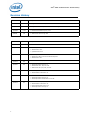
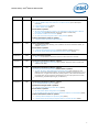

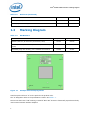
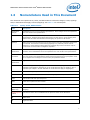
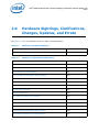
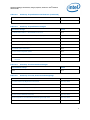
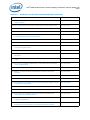
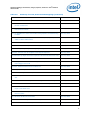


![[ 電子内視鏡 EB-530P ] ≫PDF](http://vs1.manualzilla.com/store/data/006647074_3-162e96b238c69172fbdb60a7cacfcbac-150x150.png)
![[ 電子内視鏡 EB-270P ] ≫PDF](http://vs1.manualzilla.com/store/data/006627351_2-58737137bdfa6d8ff1a009e304d4a700-150x150.png)