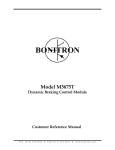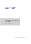
1
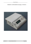
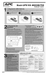
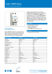
PVD40-600-V-C Surge Diverter
Class II SPD arrester in accordance with IEC
61643-1:2005. Compliance to UL1449 ed.3.
600vdc Surge Protection for PV installations
FEATURES
•
•
•
•
•
•
2 mode protection +ve - Earth, -ve - Earth
Compact solution for solar inverter protection
2 pole wide Din 43880 form factor
Replaceable plug in protection module
Includes floating-contact alarm output
Available in a range of DC voltages to 1000vdc.
Applications
•
•
Grid inter active inverters
Standby inverters
SPECIFICATIONS
Manufacturers name and model
Method of mounting
Input voltage
Maximum continuous operating
voltage - MCOV
Service type
Test classification
Supply current
Initial clamp voltage
Maximum rated surge current Ismax 8/20us
Nominal surge current –
Inom 8/20us
Residual voltage (Vpl) @ Inom
20kA, 8/20uS at terminals
Nominal surge lifetime (In)
Internal protection
External disconnector
( if required )
Terminations
Alarms/indicators
Location Category
Enclosure rating
Applicable standards.
Dimensions
Weight
Environment
Warranty
Eaton PVD40-600-V-C
Din rail mount
550 - 600VDC
620VDC
+VE – E , -VE - E
Class II
<10mA
620VDC
40kA
20kA
2.0kV
20kA (8/20uS), 20 times
MOV thermal disconnect
device.
Gg/Gl HRC fuses, 125A
maximum.
Main terminals multi strand
2
25mm
2
Alarm terminals 1.5mm
Flag indicator, alarm relay
contact 250VAC/24VDC, 2A
Indoor
IP20
IEC61643-1:2005, UL1449
ed.3
90mm (H) x 36mm (W) x
68mm (D). excluding alarm
connector
180g
-10 to 60C, 0-90%RH
12 months, workmanship
and materials
FUNCTIONAL DESCRIPTION
The PVD40-600-V-C is designed to protect
photovoltaic solar panel inverters from harmful
transients by diverting excess energy to earth from
+ve and –ve conductors to earth.
.
This model (PVD40-600-V-C) is designed for 550600vdc systems. If your power system is a
different voltage, this model is NOT suitable.
Please contact your supplier for a suitable model to
suit your application.
OPERATION
The operational status of the unit is shown by a flag
indicator on the front of the unit. In normal operation,
the flag is green. If the unit becomes damaged, the
flag changes to red, indicating that replacement is
necessary. A contact alarm output is fitted to the
base of unit and will change over if the unit is faulty.
WARRANTY
Eaton warrants this unit against faulty parts and
workmanship for a period of 12 months from the date
of purchase. If this product fails to operate correctly,
please contact your Eaton representative. This
warranty doesn’t cover neglect or intentional misuse.
As this product is intended for use in electrically
harsh environments no claim is made of suitability for
purpose. This unit is designed to reduce the
likelihood of damage. Please also note that an
excessive surge, such as from a direct lightning strike
to the site or a power system fault, may cause
damage to the unit and render it inoperable. A unit
that has been damaged in this way is not
warrantable.
For installation details,
See over page.
Specification are subject to change without notice. Copyright 2009 Eaton Industries Pty Ltd
Technical Specification –PVD40-600-V-C
Tvss Doc# 510093
Page 1 of 2
Failure to consider the above points can result in
improper operation of the unit and possible damage to
the installation.
INSTALLATION
PROCEDURE:
1.
CHECK
•
Always work safely – disconnect power before
making connections.
•
All wiring must be carried out by suitably qualified
personnel according to the applicable standards.
•
Check for correct operating voltage and power
system. This model (PVD40-600-V-C) is designed
for DC power systems in the range of 550 –
600VDC. If your power system is a different
voltage, this model is not suitable. Please
contact your supplier.
•
Always use the correct size HRC fuses.
•
Always use Gg or Gl-rated fuses. Do not use
delay types or ‘semiconductor’ fuses.
2. INSTALL
•
Locate a fuse position as close as possible to the
incoming DC breaker.
•
Install fuse holders or fuse-switch if required.
•
Locate a suitable position for the SPD, ensuring
adequate space for cables. Do not install above
heat-generating objects or in any position that is
exposed to weather.
3. CONNECT
•
Connect wiring - refer to connection diagrams. If
using stranded cable, always use wire ferrules for
lowest resistance and to prevent damage to the
wire.
•
Keep termination length as short as possible. Do
not wire in extra loops or cable length.
•
Use a suitably-rated cable for alarm connections.
Cable should be rated for operation at the system
voltage and should be 0.5mm2 to 1.5mm2.
4. NOTES:
•
125A fuses are rated such for maximum surge
rating. On services below 125A, fit a fuse lower in
value to the service size.
•
Wiring from fuse to SPD is carrying surge currents
only, not load current. This means that smaller
cables may be used than is normal for the current
rating.
•
If using under-sized cables, some energy
authorities require double insulation (i.e. sleeving)
of the cables.
•
Unplug the alarm connector for termination.
•
Do not Megger test cabling with unit connected –
unit may be damaged.
Electrical configuration diagram
EARTHING
For proper operation, all surge diverters rely upon a good
earth connection:
• The main earth wire (from earth link on switchboard to
ground rod or system) MUST be as short and direct as
possible. Extra cable must not be looped.
• Earth connections from the unit to earth link MUST be
as short as possible.
Specification are subject to change without notice. Copyright 2009 Eaton Industries Pty Ltd
Technical Specification –PVD40-600-V-C
Tvss Doc# 510093
Page 2 of 2