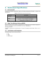
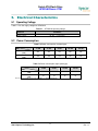
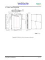
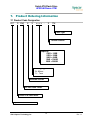
1
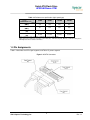
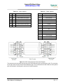
RoHS Compliant
Serial ATA Flash Drive
SFD25A -M Product Specifications
November 21st, 2013
Version 1.1
Apacer Technology Inc.
1F, No.32, Zhongcheng Rd., Tucheng Dist., New Taipei City, Taiwan, R.O.C
Tel: +886-2-2267-8000
www.apacer.com
Fax: +886-2-2267-2261
Serial ATA Flash Drive
APS25AXXxxxx-XTM
Features:
Compliance with SATA Revision 3.1
– Serial ATA Revision 3.1
– SATA 6.0 Gbps interface
– Backward compatible with SATA 1.5 and
3.0 Gbps interfaces
– ATA-8 command set
Temperature ranges
– Operating: 0°C to 70°C (32 ~ 158°F)
– Storage: -40°C to 100°C (-40° ~ 212°F)
Supply voltage
– 5.0 V
5%
Capacities
– Standard type: 16, 32, 64, 128, 256 GB
– High-speed type: 32, 64, 128, 256 GB
Performance*
– Burst read/write: 600 MB/sec
Standard type:
– Sustained read: up to 385 MB/sec
– Sustained write: up to 170 MB/sec
High-speed type:
– Sustained read: up to 450 MB/sec
– Sustained write: up to 430 MB/sec
– Random read (4K): up to 63,000 IOPS
– Random write (4K): up to 63,000 IOPS
Power consumption (typical)*
Standard type:
– Active mode: 385 mA
– Idle mode: 105 mA
High-speed type:
– Active mode: 665 mA
– Idle mode: 70 mA
Form factor
– 2.5”
– Dimensions with 7mm enclosure:
100.00 x 69.85 x 6.90, unit: mm
– Dimensions with 9.5mm enclosure:
100.00 x 69.84 x 9.30, unit: mm
Flash Management
– Built-in hardware ECC, enabling up to 40
bit correction per 1K bytes
– Static/dynamic wear leveling
– Flash bad-block management
– S.M.A.R.T.
– Power Failure Management
– ATA Secure Erase
– TRIM
Connector
– 7-pin SATA signal connector
– 15-pin SATA power connector
Shock & Vibration**
– Shock: 1500 G
– Vibration: 15 G
DRAM cache for enhanced random
performance (for high-speed type only)
NAND Flash Type: MLC
SATA power management modes
Device Sleep mode (optional)
RoHS compliant
±
*The values addressed here are typical and may vary depending on settings and platforms.
**Non-operating
1
©2013 Apacer Technology Inc.
Rev. 1.1
Serial ATA Flash Drive
APS25AXXxxxx-XTM
Table of Contents
1.
Product Description ............................................................................................... 3
1.1 Introduction .................................................................................................................................................3
1.2 Capacity Specification ................................................................................................................................3
1.3 Performance.................................................................................................................................................3
1.4 Pin Assignments ..........................................................................................................................................4
2.
Software Interface................................................................................................... 6
2.1 Command Set ..............................................................................................................................................6
2.2 S.M.A.R.T....................................................................................................................................................6
3.
Flash Management ................................................................................................. 8
3.1 Error Correction/Detection ........................................................................................................................8
3.2 Bad Block Management .............................................................................................................................8
3.3 Wear Leveling .............................................................................................................................................8
3.4 Power Failure Management .......................................................................................................................8
3.5 ATA Secure Erase .......................................................................................................................................8
3.6 TRIM ...........................................................................................................................................................9
3.7 SATA Power Management ........................................................................................................................9
4.
Environment Specifications ................................................................................ 10
4.1 Environmental ..........................................................................................................................................10
4.2 Mean Time Between Failures (MTBF)....................................................................................................10
4.3 Certification and Compliance ..................................................................................................................10
5.
Electrical Characteristics..................................................................................... 11
5.1 Operating Voltage .....................................................................................................................................11
5.2 Power Consumption .................................................................................................................................11
6.
Mechanical Specifications ................................................................................... 12
6.1
6.2
7.
7mm Type Dimensions .............................................................................................................................12
9.5mm Type Dimensions ..........................................................................................................................13
Product Ordering Information ............................................................................. 14
7.1
7.2
Product Code Designation........................................................................................................................14
Valid Combination....................................................................................................................................15
2
©2013 Apacer Technology Inc.
Rev. 1.1
Serial ATA Flash Drive
APS25AXXxxxx-XTM
1. Product Description
1.1 Introduction
Apacer’s SFD25A-M is a well-balanced solid-state disk (SSD) drive with standard form factor and great
performance. Designed in SATA 6.0 Gbps interface, the SSD is able to deliver exceptional read/write speed,
making it the ideal companion for heavy-loading industrial or server operations.
For data efficiency, the internal controlling unit of the SSD is engineered with DRAM for enhanced random
performance (for high-speed type only). In regard of reliability, the drive comes with various implementations
including powerful hardware ECC engine, power saving modes, wear leveling, flash block management,
S.M.A.R.T., TRIM, and power failure management.
1.2
Capacity Specification
Table 1-1 Capacity specification
Capacity
Total Bytes*
Cylinders
Heads
Sectors
Max LBA*
16 GB
16,013,942,784
16,383
16
63
31,277,232
32 GB
32,017,047,552
16,383
16
63
62,533,296
64 GB
64,023,257,088
16,383
16
63
125,045,424
128 GB
128,035,676,160
16,383
16
63
250,069,680
256 GB
256,060,514,304
16383
16
63
500,118,192
*Display of total bytes varies from file systems.
**Cylinders, heads or sectors are not applicable for these capacities. Only LBA addressing applies.
LBA count addressed in the table above indicates total user storage capacity and will remain the same throughout the lifespan of
the device. However, the total usable capacity of the SSD is most likely to be less than the total physical capacity because a small
portion of the capacity is reserved for device maintenance usages.
1.3
Performance
Table 1-2 Performance (standard type)
Capacity
Performance
Sustained Read
(MB/s)
Sustained Write
(MB/s)
16 GB
32 GB
64 GB
128 GB
256 GB
200
370
350
385
385
22
42
80
170
170
Note: Performance varies from flash configurations or host system settings. The result of 256GB is based on estimation.
3
©2013 Apacer Technology Inc.
Rev. 1.1
Serial ATA Flash Drive
APS25AXXxxxx-XTM
Table 1-3 Performance specification (high-speed type)
Capacity
Performance
Sustained Read
(MB/s)
Sustained Write
(MB/s)
Random Read IOPS
(4K)
Random Write IOPS
(4K)
32 GB
64 GB
128 GB
256 GB
370
450
450
450
80
145
300
430
43,000
63,000
63,000
63,000
18,000
31,000
63,000
63,000
Note: Performance varies from flash configurations or host system settings.
IOPS: measured on 8GB span (16777216 sectors Disk Size), 32 Outstanding I/Os (QD=32), Full Random Data pattern,
4KB Align I/Os and test durations 15minutes.
1.4 Pin Assignments
Table 1-4 describes the SFD signal segment, and Table1-5, power segment.
Figure 1-2 SATA Connectors
4
©2013 Apacer Technology Inc.
Rev. 1.1
Serial ATA Flash Drive
APS25AXXxxxx-XTM
Table 1-4:
Pin
Type
S1
GND
Table 1-5:
Signal segment
Description
Power segment
Pin
Signal/Description
P1
Unused (3.3V)
S2
RxP
+ Differential Receive Signal
P2
Unused (3.3V)
S3
RxN
- Differential Receive Signal
P3
Unused (3.3V)
S4
GND
P4
Ground
S5
TxN
- Differential Transmit Signal
P5
Ground
S6
TxP
+ Differential Transmit Signal
P6
Ground
S7
GND
P7
5V
P8
5V
P9
5V
P10
Ground
P11
DAS
P12
Ground
P13
Unused (12V)
P14
Unused (12V)
P15
Unused (12V)
Figure 1-3 SATA Cable/Connector Connection Diagram
The connector on the left represents the Host with TX/RX differential pairs connected to a cable. The connector
on the right shows the Device with TX/RX differential pairs also connected to the cable. Notice also the ground
path connecting the shielding of the cable to the Cable Receptacle.
5
©2013 Apacer Technology Inc.
Rev. 1.1
Serial ATA Flash Drive
APS25AXXxxxx-XTM
2. Software Interface
2.1
Command Set
Table 2-1 summarizes the ATA commands supported by SFD25A-M.
Table 2-1:
Code
Command set
Command
Code
Command
E5h
Check Power Mode
F6h
Security Disable Password
90h
Execute Diagnostics
F3h
Security Erase Prepare
E7h
Flush Cache
F4h
Security Erase Unit
ECh
Identify Device
F5h
Security Freeze Lock
E3h
Idle
F1h
Security Set Password
E1h
Idle Immediate
F2h
Security Unlock
91h
Initialize Device Parameters
7xh
Seek
C8h
Read DMA
EFh
Set Features
25h
Read DMA EXT
C6h
Set Multiple Mode
60h
Read FPDMA Queued
E6h
Sleep
47h
Read Log DMA EXT
B0h
S.M.A.R.T.
2Fh
Read Log EXT
E2h
Standby
C4h
Read Multiple
E0h
Standby Immediate
20 or 21h
Read Sector(s)
CAh
Write DMA
40 or 41h
Read Verify Sector(s)
35h
Write DMA EXT
10h
Recalibrate
61h
Write FPDMA Queued
57h
Write Log DMA EXT
3Fh
Write Log EXT
C5h
Write Multiple
30h or 31h
Write Sector(s)
2.2
S.M.A.R.T.
S.M.A.R.T. is an abbreviation for Self-Monitoring, Analysis and Reporting Technology, a self-monitoring
system that provides indicators of drive health as well as potential disk problems. It serves as a warning for
users from unscheduled downtime by monitoring and displaying critical drive information. Ideally, this should
allow taking proactive actions to prevent drive failure and make use of S.M.A.R.T. information for future product
development reference.
Apacer devices use the standard SMART command B0h to read data out from the drive to activate our
S.M.A.R.T. feature that complies with the ATA/ATAPI specifications. S.M.A.R.T. Attribute IDs shall include
initial bad block count, total later bad block count, maximum erase count, average erase count, power on hours
and power cycle. When the S.M.A.R.T. Utility running on the host, it analyzes and reports the disk status to the
host before the device reaches in critical condition.
Note: attribute IDs may vary from product models due to various solution design and supporting capabilities.
6
©2013 Apacer Technology Inc.
Rev. 1.1
Serial ATA Flash Drive
APS25AXXxxxx-XTM
Apacer memory products come with S.M.A.R.T. commands and subcommands for users to obtain information
of drive status and to predict potential drive failures. Users can take advantage of the following
commands/subcommands to monitor the health of the drive.
Code
D0h
D1h
D2h
D4h
D5h
D6h
D8h
D9h
DAh
Byte
0
1–2
3
4
5*-11
SMART Subcommand
READ DATA
READ ATTRIBUTE THRESHOLDS
Enable/Disable Attribute Autosave
Execute Off-line Immediate
Read Log (optional)
Write Log (optional)
Enable Operations
Disable operations
Return Status
General SMART attribute structure
Description
ID (Hex)
Status flag
Value
Worst
Raw Data
*Byte 5: LSB
ID (Hex)
9 (0x09)
12 (0x0C)
163 (0xA3)
164 (0xA4)
166 (0xA6)
167 (0xA7)
168 (0xA8)
175 (0xAF)
192 (0xC0)
194 (0xC2)
241 (0xF1)
SMART attribute ID list
Attribute Name
Power-on hours
Power cycle count
Max. erase count
Avg. erase count
Total later bad block count
SSD Protect Mode (vendor specific)
SATA PHY Error Count
Bad Cluster Table Count
Unexpected Power Loss Count
Temperature
Total sectors of write
7
©2013 Apacer Technology Inc.
Rev. 1.1
Serial ATA Flash Drive
APS25AXXxxxx-XTM
3. Flash Management
3.1 Error Correction/Detection
SFD25A-M implements a hardware ECC scheme, based on the BCH algorithm. It can detect and correct up to
40 bits error in 1K bytes.
3.2 Bad Block Management
Current production technology is unable to guarantee total reliability of NAND flash memory array. When a
flash memory device leaves factory, it comes with a minimal number of initial bad blocks during production or
out-of-factory as there is no currently known technology that produce flash chips free of bad blocks. In addition,
bad blocks may develop during program/erase cycles. When host performs program/erase command on a
block, bad block may appear in Status Register. Since bad blocks are inevitable, the solution is to keep them in
control. Apacer flash devices are programmed with ECC, block mapping technique and S.M.A.R.T to reduce
invalidity or error. Once bad blocks are detected, data in those blocks will be transferred to free blocks and
error will be corrected by designated algorithms.
3.3 Wear Leveling
Flash memory devices differ from Hard Disk Drives (HDDs) in terms of how blocks are utilized. For HDDs,
when a change is made to stored data, like erase or update, the controller mechanism on HDDs will perform
overwrites on blocks. Unlike HDDs, flash blocks cannot be overwritten and each P/E cycle wears down the
lifespan of blocks gradually. Repeatedly program/erase cycles performed on the same memory cells will
eventually cause some blocks to age faster than others. This would bring flash storages to their end of service
term sooner. Wear leveling is an important mechanism that level out the wearing of blocks so that the
wearing-down of blocks can be almost evenly distributed. This will increase the lifespan of SSDs. Commonly
used wear leveling types are Static and Dynamic.
3.4 Power Failure Management
Power Failure Management plays a crucial role when experiencing unstable power supply. Power disruption
may occur when users are storing data into the SSD. In this urgent situation, the controller would run multiple
write-to-flash cycles to store the metadata for later block rebuilding. This urgent operation requires about
several milliseconds to get it done. At the next power up, the firmware will perform a status tracking to retrieve
the mapping table and resume previously programmed NAND blocks to check if there is any incompleteness of
transmission.
Note: The controller unit of this product model is designed with a DRAM as a write cache for improved performance and data efficiency.
Though unlikely to happen in most cases, the data cached in the volatile DRAM might be potentially affected if a sudden power loss takes
place before the cached data is flushed into non-volatile NAND flash memory.
3.5 ATA Secure Erase
ATA Secure Erase is an ATA disk purging command currently embedded in most of the storage drives. Defined
in ATA specifications, (ATA) Secure Erase is part of Security Feature Set that allows storage drives to erase all
user data areas. The erase process usually runs on the firmware level as most of the ATA-based storage
media currently in the market are built-in with this command. ATA Secure Erase can securely wipe out the user
data in the drive and protects it from malicious attack.
8
©2013 Apacer Technology Inc.
Rev. 1.1
Serial ATA Flash Drive
APS25AXXxxxx-XTM
3.6 TRIM
TRIM is a SATA command that helps improve the read/write performance and efficiency of solid-state drives
(SSD). The command enables the host operating system to inform SSD controller whick blocks contain invalid
data, mostly because of the erase commands from host. The invalid will be discarded permanently and the
SSD will retain more space for itself.
3.7 SATA Power Management
By complying with SATA 6.0 Gb/s specifications, the SSD supports the following SATA power saving modes:
ACTIVE: PHY ready, full power, Tx & Rx operational
PARTIAL: Reduces power, resumes in under 10 µs (microseconds)
SLUMBER: Reduces power, resumes in under 10 ms (milliseconds)
HIPM: Host-Initiated Power Management
DIPM: Device-Initiated Power Management
AUTO-SLUMBER: Automatic transition from partial to slumber.
Device Sleep (DevSleep or DEVSLP): PHY powered down; power consumption
5 mW; host assertion
time
10 ms; exit timeout from this state
20 ms (unless specified otherwise in SATA Identify Device
Log).
≦
≦
≦
Note:
1. The behaviors of power management features would depend on host/device settings.
2. Device Sleep mode is optional, depending on product ordering selections.
9
©2013 Apacer Technology Inc.
Rev. 1.1
Serial ATA Flash Drive
APS25AXXxxxx-XTM
4. Environment Specifications
4.1
Environmental
SFD25A-M environmental specifications follow the US Military Standard MIL-STD-810F, as shown in the
following table.
Table 4-1 SFD25A-M environmental specifications
Environment
Specification
0°C to 70°C (Operating)
Temperature
Vibration
Shock
4.2
-40°C to 100°C (Non-operating)
Non-operating : Sine wave, 15(G), 10~2000(Hz),
Operating : Random, 7.69(Grms), 20~2000(Hz)
Non-operating: Acceleration, 1,500 G, 0.5 ms
Operating: Peak acceleration, 50 G, 11 ms
Mean Time Between Failures (MTBF)
Mean Time Between Failures (MTBF) is predicted based on reliability data for the individual components in
SFD drive. The prediction result for the SFD25A-M is more than 1,000,000 hours.
Notes about the MTBF:
The MTBF is predicated and calculated based on “Telcordia Technologies Special Report, SR-332, Issue 2”
method.
4.3
Certification and Compliance
SFD25A-M complies with the following standards:
CE
FCC
RoHS
MIL-STD-810F
10
©2013 Apacer Technology Inc.
Rev. 1.1
Serial ATA Flash Drive
APS25AXXxxxx-XTM
5. Electrical Characteristics
5.1 Operating Voltage
Table 5-1 lists the supply voltage for SFD25A-M.
Table 5-1
SFD25A-M operating voltage
Parameter
Conditions
Supply voltage
5.2
5V ±5%
( 4.75-5.25 V)
Power Consumption
Table 5-2 Power consumption (standard type)
Capacity
Mode
Active
(mA)
Idle
(mA)
16 GB
32 GB
64 GB
128 GB
256 GB
255
255
255
385
385
105
105
105
105
105
Notes: Results of 16GB, 32GB and 256GB are based on estimation.
Table 5-3 Power consumption (high-speed type)
Capacity
Mode
Active
(mA)
Idle
(mA)
32 GB
64 GB
128 GB
256 GB
235
300
455
665
70
70
70
70
Note: Power consumptions may vary depending on settings and platforms.
11
©2013 Apacer Technology Inc.
Rev. 1.1
Serial ATA Flash Drive
APS25AXXxxxx-XTM
6. Mechanical Specifications
6.1 7mm Type Dimensions
㎜
Unit:
Tolerance: ± 0.2
Figure 6-1 SFD25A-M with 7mm Housing physical dimensions
12
©2013 Apacer Technology Inc.
Rev. 1.1
Serial ATA Flash Drive
APS25AXXxxxx-XTM
6.2 9.5mm Type Dimensions
㎜
Unit:
Tolerance: ± 0.2
Figure 6-2 SFD25A-M with 9.5mm Housing physical dimensions
13
©2013 Apacer Technology Inc.
Rev. 1.1
Serial ATA Flash Drive
APS25AXXxxxx-XTM
7. Product Ordering Information
7.1 Product Code Designation
AP
S 25A
X
X
xxxx -
X
TM
Flash Type
Version Control
Capacity:
016G = 16GB
032G = 32GB
064G = 64GB
128G = 128GB
256G = 256GB
Housing Type
B= 9.5mm
7= 7mm
Solution version
2.5 inch Form Factor
Serial ATA Flash Drive
Apacer Product Code
14
©2013 Apacer Technology Inc.
Rev. 1.1
Serial ATA Flash Drive
APS25AXXxxxx-XTM
7.2 Valid Combination
7.2.1 9.5mm Metal Housing – Standard
Capacity
16GB
32GB
64GB
128GB
256GB
NO DEVSLP
APS25ABB032G-ATM
APS25ABB032G-ATM
APS25ABB064G-ATM
APS25ABB128G-ATM
APS25ABB256G-ATM
DEVSLP
APS25ABB032G-BTM
APS25ABB032G-BTM
APS25ABB064G-BTM
APS25ABB128G-BTM
APS25ABB256G-BTM
7.2.2 7mm Housing – Standard
Capacity
16GB
32GB
64GB
128GB
256GB
NO DEVSLP
APS25AB7016G-ATM
APS25AB7032G-ATM
APS25AB7064G-ATM
APS25AB7128G-ATM
APS25AB7256G-ATM
DEVSLP
APS25AB7016G-BTM
APS25AB7032G-BTM
APS25AB7064G-BTM
APS25AB7128G-BTM
APS25AB7256G-BTM
7.2.3 9.5mm Metal Housing – High Speed
Capacity
32GB
64GB
128GB
256GB
NO DEVSLP
APS25A4B032G-ATM
APS25A7B064G-ATM
APS25A7B128G-ATM
APS25A7B256G-ATM
DEVSLP
APS25A4B032G-BTM
APS25A7B064G-BTM
APS25A7B128G-BTM
APS25A7B256G-BTM
7.2.4 7mm Housing – High Speed
Capacity
32GB
64GB
128GB
256GB
NO DEVSLP
APS25A47032G-ATM
APS25A77064G-ATM
APS25A77128G-ATM
APS25A77256G-ATM
DEVSLP
APS25A47032G-BTM
APS25A77064G-BTM
APS25A77128G-BTM
APS25A77256G-BTM
Note: Please consult with Apacer sales representatives for availabilities.
15
©2013 Apacer Technology Inc.
Rev. 1.1
Serial ATA Flash Drive
APS25AXXxxxx-XTM
Revision History
Revision
Description
Date
0.1
Preliminary release
05/17/2013
0.2
Updated mechanical drawings
08/30/2013
0.3
Added performance and power consumption information for 64, 128
and 256 GB
09/05/2013
0.4
Added IOPS
10/11/2013
Integrates categories of standard and high-speed types
1.0
Official release
11/07/2013
1.1
Updated performance and power consumption due to changes in
components
11/21/2013
16
©2013 Apacer Technology Inc.
Rev. 1.1
Serial ATA Flash Drive
APS25AXXxxxx-XTM
Global Presence
Taiwan (Headquarters)
Apacer Technology Inc.
1F., No.32, Zhongcheng Rd., Tucheng Dist.,
New Taipei City 236, Taiwan R.O.C.
Tel: 886-2-2267-8000
Fax: 886-2-2267-2261
[email protected]
U.S.A.
Apacer Memory America, Inc.
386 Fairview Way, Suite102,
Milpitas, CA 95035
Tel: 1-408-518-8699
Fax: 1-408-935-9611
[email protected]
Japan
Apacer Technology Corp.
5F, Matsura Bldg., Shiba, Minato-Ku
Tokyo, 105-0014, Japan
Tel: 81-3-5419-2668
Fax: 81-3-5419-0018
[email protected]
Europe
Apacer Technology B.V.
Science Park Eindhoven 5051 5692 EB Son,
The Netherlands
Tel: 31-40-267-0000
Fax: 31-40-267-0000#6199
[email protected]
China
Apacer Electronic (Shanghai) Co., Ltd
1301, No.251,Xiaomuqiao Road, Shanghai,
200032, China
Tel: 86-21-5529-0222
Fax: 86-21-5206-6939
[email protected]
India
Apacer Technologies Pvt Ltd,
# 535, 1st Floor, 8th cross, JP Nagar 3rd Phase,
Bangalore – 560078, India
Tel: 91-80-4152-9061
[email protected]
17
©2013 Apacer Technology Inc.
Rev. 1.1