1
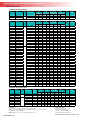
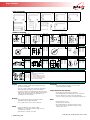
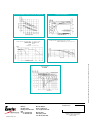
Range Summary
Publication No: US-NP-RS-004 • March 2008
Sealed Rechargeable, Valve Regulated Lead-Acid Batteries
GENERAL SPECIFICATIONS
GENESIS™ NPH BATTERY SERIES
Type
FR Type*
Volts
—————
NPH2-12FR
NPH3.2-12
NPH3.2-12FR
Nominal Capacity
(10hr rate-Ah)
12
Length
Width
Overall Height
incl. Terminals
Weight
Layout
Terminal
Illustration
mm
(in.)
mm
(in.)
mm
(in.)
kgs.
(lbs)
2
68
2.68
51
2.01
88
3.46
0.84
1.85
2
A
3.2
134
5.28
67
2.64
64
2.52
1.38
3.05
3
A/C
Layout
Terminal
Illustration
A
GENESIS™ NP BATTERY SERIES
Type
FR Type*
Volts
Nominal Capacity
(20hr rate-Ah)
mm
(in.)
mm
(in.)
mm
(in.)
kgs.
(lbs)
NP1-6
NP1-6FR
1.0
51
2.01
42
1.65
57
2.24
0.28
0.61
5
NP1.2-6
NP1.2-6FR
1.2
97
3.82
25
0.98
56
2.20
0.30
0.67
1
A
NP2.8-6
NP2.8-6FR
2.8
67
2.64
33
1.30
105
4.13
0.59
1.30
5
A/C
NP3-6
NP3-6FR
3.0
134
5.28
33
1.30
67
2.64
0.69
1.53
1
A
NP3.2-6
NP3.2-6FR
3.2
66
2.60
33
1.30
104
4.09
0.59
1.30
5
A
NP3.8-6
NP3.8-6FR
3.8
66
2.60
33
1.30
125
4.92
0.75
1.65
1
A
NP4-6
NP4-6FR
4.0
70
2.76
47
1.85
105
4.15
0.80
1.76
5
A/C
NP4.5-6
NP4.5-6FR
4.5
70
2.76
47
1.85
105
4.15
0.86
1.90
5
A/C
NP5-6
NP5-6FR
5.0
70
2.76
47
1.85
105
4.15
0.95
2.10
5
A/C
NP7-6
NP7-6FR
7.0
151
5.95
33
1.30
100
3.94
1.28
2.83
1
A/C
NP8.5-6
NP8.5-6FR
8.5
98
3.86
56
2.20
118
4.65
1.60
3.53
9
A/C
NP10-6
NP10-6FR
10.0
151
5.95
50
1.97
101
3.98
1.99
4.38
1
A/C
NP12-6
NP12-6FR
12.0
151
5.95
50
1.97
101
3.98
2.04
4.48
1
A/C
NP0.8-12
NP0.8-12FR
0.8
96
3.78
25
0.98
61
2.42
0.37
0.82
7
H/I
NP1.2-12
NP1.2-12FR
1.2
97
3.82
48
1.89
56
2.20
0.57
1.25
3
A
NP2-12
NP2-12FR
2.0
150
5.91
20
0.79
89
3.50
0.70
1.54
8
B
NP2-12-C
NP2-12CFR
2.0
182
7.17
24
0.93
61
2.40
0.73
1.61
6
L
NP2.3-12
NP2.3-12FR
2.3
178
7.01
35
1.38
67
2.64
1.02
2.15
1
A
NP2.6-12
NP2.6-12FR
2.6
134
5.28
67
2.64
66
2.60
1.36
3.00
3
A
NP2.9-12
NP2.9-12FR
2.9
79
3.11
56
2.20
105
4.13
1.24
2.73
1
A/C
NP3-12
NP3-12FR
3.0
132
5.20
33
1.30
105
4.13
1.18
2.60
1
A/C
NP3.4-12
NP3.4-12FR
3.4
134
5.28
67
2.64
67
2.64
1.39
3.06
3
A/C
NP4-12
NP4-12FR
4.0
90
3.54
70
2.76
107
4.21
1.70
3.74
1
A/C
NP4.5-12
NP4.5-12FR
4.5
90
3.54
70
2.76
107
4.21
1.76
3.88
1
A/C
NP5-12
NP5-12FR
5.0
90
3.54
70
2.76
107
4.21
1.81
4.00
1
A/C
NP7-12
NP7-12FR
7.0
151
5.95
65
2.56
100
3.94
2.59
5.72
4
A/C
NP12-12
NP12-12FR
12.0
151
5.95
98
3.86
100
3.94
4.06
8.95
4
C
NP18-12
NP18-12FR
17.2
181
7.13
76
3.00
167
6.57
6.17
13.60
2
D/E
NP24-12
NP24-12FR
24.0
166
6.54
175
6.89
125
4.92
9.07
20.00
2
C/D/E
NP33-12
NP33-12FR
33.0
197
7.76
131
5.16
158+
6.22+
11.79
26.00
1
E/F
NP35-12
NP35-12FR
35.0
198
7.80
132
5.20
170
6.69
12.61
27.80
1
F
NP38-12
NP38-12FR
38.0
197
7.76
165
6.50
172
6.77
14.59
32.16
2
F/G
NP55-12
NP55-12FR
56.3
229
9.02
138
5.43
207+
8.15+
18.01
39.70
1
M/G
NP65-12
NP65-12FR
65.0
350
13.78
166
6.54
174
6.85
23.63
52.10
2
F/G
NP75-12
NP75-12FR
77.5
259
10.20
169
6.65
208+
8.19+
26.50
58.42
1
M/G
NP90-12
NP90-12FR
90.0
304
11.97
168
6.61
229+
9.02
31.18
68.74
1
M/G
NP100-12
NP100-12FR
100.0
329
12.95
174
6.85
214+
8.43+
32.94
72.62
1
J/G
NP120-12
NP120-12FR
120.0
407
16.02
173
6.81
235
9.25
38.41
84.68
1
J/G
NP150-12
NP150-12FR
150.0
483
19.02
170
6.69
241
9.49
47.13
103.90
1
J/G
NP200-12
NP200-12FR
200.0
520
20.47
260
10.24
208
8.19
73.00
160.93
3
K/G
Layout
Terminal
Illustration
6
12
Length
Width
Overall Height
incl. Terminals
Weight
DATASAFE™ NPX BATTERY SERIES
Type
FR Type*
NPX-35-6
NPX-35-6FR
NPX-50
NPX-50FR
NPX-25
Volts
Watts/Cell to
1.67 End Voltage
Nominal
Capacity
(20hr
rate-Ah)
mm
(in.)
mm
(in.)
mm
(in.)
kgs.
(lbs)
35W/Cell
8
151
5.95
33
1.30
100
3.94
1.43
3.15
1
A/C
50W/Cell
13
151
5.95
50
1.97
100
3.94
2.09
4.60
1
A/C
NPX-25FR
23W/Cell
5
90
3.54
70
2.75
107
4.21
1.95
4.30
1
A/C
NPX-35
NPX-35FR
35W/Cell
8
151
5.95
65
2.56
100
3.94
2.75
6.06
4
A/C
NPX-80
NPX-80FR
80W/Cell
20
181
7.13
76
2.39
167
6.57
6.35
14.00
2
D/E
NPX-100
NPX-100FR
95W/Cell
28
166
6.54
125
4.92
175
6.89
9.70
21.38
2
D/E
NPX-135
NPX-135FR
135W/Cell
33
197
7.76
131
5.16
158+
6.22
11.94
26.32
1
E/F
NPX-150
NPX-150FR
150W/Cell
40
197
7.76
165
6.50
172
6.77
14.29
31.50
2
F/G
6
12
Length
Width
Overall Height
incl. Terminals
Weight
FOOTNOTES:
Torque Specifications:
* FR: UL94-VO, Flame Retardant Case and Cover (Oxygen index 28)
+ Height is top cover. Overall Height, including terminal is dependent on the terminal configuration
Recognized by UL File No. MH16464
M5 bolt: 26.6 lbf.in (3Nm) +/- 5%
M6 bolt: 44.31 lbf.in (5Nm) +/- 5%
M5 receptacle: 35.4 lbf.in (4Nm) +/- 5%
M6 receptacle: 65 lbf.in (6.8Nm) +/- 5%
NOTE: All dimensions are +/- 0.08 inches (2mm); Weights are +/- 5%
2 www.enersys.com
Publication No: US-NP-RS-004 • March 2008
Range Summary
LAYOUT ILLUSTRATION
1
2
3
4
6
7
8
9
5
TERMINAL ILLUSTRATION
A
M5
E
M5 Threaded Receptacle
M
F
INCH = MM
0.806
20.47
0.760
19.30
0.690
17.53
0.630
16.00
0.394
10.01
0.335
8.50
INCH = MM
0.709
0.551
0.256
0.236
J
G
M6 Threaded Receptacle
K
INCH = MM
1.024
26.01
0.910
23.11
0.430
10.92
0.335
8.51
0.315
8.00
M8 Bolt Fastened Terminal
INCH = MM
0.472
11.99
0.453
11.51
0.217
5.51
0.079
2.01
M5 Bolt Fastened Terminal
M6
18.01
14.00
6.50
5.99
D
INCH = MM
0.313
7.95
0.250
6.35
0.180
4.57
0.098
2.49
0.059
1.50
0.031
0.79
0.020
0.51
0.004
0.10
Faston Tab: 250
M6 Bolt Fastened Terminal
INCH = MM
0.860
21.84
0.530
13.46
0.430
10.92
0.295
7.49
Tyco. 1-480318-0
M8
C
INCH = MM
0.472
11.99
0.250
6.35
0.236
5.99
0.187
4.75
0.130
3.30
0.079
2.01
0.020
0.51
Faston Tab: 187
Faston Tab: 187
I
B
INCH = MM
0.250
6.35
0.187
4.75
0.124
3.15
0.098
2.49
0.059
1.50
0.031
0.79
0.020
0.51
0.004
0.10
INCH = MM
1.100
27.94
0.910
23.11
0.510
12.95
0.390
9.91
0.330
8.38
M10 Bolt Fastened Terminal
H
INCH = MM
0.530
13.46
0.420
10.67
0.310
7.87
0.230
5.84
0.160
4.06
JST No. VHR-2N
L
INCH = MM
0.870
22.01
0.550
13.97
0.430
10.92
0.230
5.84
“Camcorder” Terminal
Note:
Dimensions are in inches (mm)
Tolerances are
± 0.02 in. for dimensions < 5mm
± 0.04 in. for dimensions ≥ 5mm
± 0.08 in. for all height dimensions
unless otherwise specified.
M8 “Universal” Bolt Fastened Terminal
Charging
Temperature
•S
tandby use: Apply constant voltage charging at 2.275 volts
per cell (or 2.25–2.30VPC).
•C
yclic use: Apply constant voltage charging at 2.40-2.50 VPC.
Initial charging current should be set at less than 0.25CA.
•T
op charge: Product in storage (ambient temperature 25°C/77°F)
requires a top charge every six months. Apply constant voltage at
2.40 volts per cell, initial charging current should be set at less than 0.1CA for 15 to 20 hours.
Discharge
•K
eep within ambient temperatures of –15°C to +50°C
for both charging and discharging.
Incorporating battery into equipment
• Encase battery in a well ventilated compartment.
• Avoid installing battery near heated units such as a transformer.
•H
ouse the battery in the lowest section of the equipment
enclosure or rack to prevent unnecessary battery temperature rise.
•S
top operation when voltage has reached the minimum
permissible voltage. Recharge immediately.
Others
• Avoid terminal short circuit.
• Do not operate at 6CA or more current continuously.
• DO NOT expose to open flame.
•A
void setting batteries in environments which can cause
direct contact to gasoline, paint thinner, organic solvents,
synthetic resins, oil, etc.
Storage
• Always store battery in a fully charged condition.
• If battery is to be stored for a long period, apply a recovery
top-charge every 6 months.
• Store batteries in a dry and cool location.
3 www.enersys.com
Publication No: US-NP-RS-004 • March 2008
CHARGING CHARACTERISTICS
RELATIONSHIP BETWEEN CHARGING VOLTAGE AND TEMPERATURE
Charging Time (Hours)
Ambient Temperature
FLOAT SERVICE LIFE NP SERIES
CYCLE SERVICE LIFE IN RELATION TO DEPTH OF DISCHARGE NP SERIES
TESTING CONDITIONS: FLOATING VOLTAGE: 2.25 TO 2.30V/CELL
AMBIENT TEMPERATURE: 20ºC TO 22ºC (68ºF TO 72ºF)
TESTING CONDITIONS: DISCHARGE CURRENT: 0.17C Amp. (F.V. 1.7V/CELL)
CHARGING CURRENT: 0.09C Amp.
CHARGING VOLUME: 125% OF DISCHARGED
CAPACITY
AMBIENT
TEMPERATURE: 20º C (68ºF TO 77ºF)
Life (Year)
Publication No: US-NP-RS-004 • March 2008 - Subject to revisions without prior notice E & OE
Number of Cycles
DISCHARGE CHARACTERISTICS
Curves at 25ºC (77ºF)
NP SERIES
EnerSys
P.O. Box 14145
Reading, PA 19612-4145
USA
Tel:+1-610-208-1991
+1-800-538-3627
www.enersys.com
EnerSys Europe
Zurich, Switzerland
Tel: +41 (0) 44 215 74 10
EnerSys Asia
Guangdong, China
Tel: +86 755 2689 3639
Distributed by:
© 2008 EnerSys. All rights reserved.
Trademarks and logos are the property
of EnerSys and its affiliates unless
otherwise noted.