1
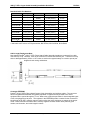
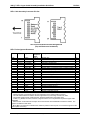
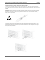
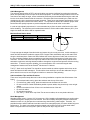
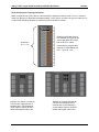
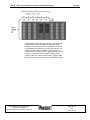
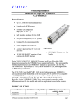
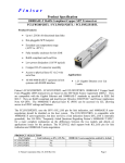
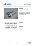
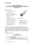
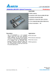
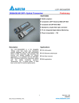
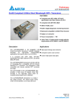
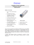
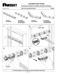
Installation Guidelines, 10Gig™ SFP+ Direct Attach Copper Cable Assembly PN533A Introduction As virtualization, consolidation, and convergence initiatives continue to expand in Data Centers, so do the demands placed on the physical infrastructure. To meet the needs for higher bandwidth along with lower ® power interconnects, Panduit offers 10Gig™ SFP+ Direct Attach Copper Cable Assemblies. This high speed data transport capability is ideal as server virtualization becomes more prevalent. 10Gig interconnects are needed to facilitate effective server utilization to run multiple virtual machines as well as server consolidation. By incorporating 10Gig™ SFP+ Copper Cable Assemblies into the physical infrastructure, organizations can achieve 10Gig performance without additional signal processing or conversion. This provides an ideal low power, low latency 10 Gbps server interconnect option for top of rack switching deployments. Passive 10Gig™ SFP+ Copper Cable Assemblies generally have a reach limitation of 7 meters (23 feet), and many network deployments will consist of a mixed copper/fiber solution with Panduit 10Gig™ OM3 fiber. Panduit 10Gig™ SFP+ Direct Attach Copper Cable Assemblies ™ Panduit 10Gig SFP+ Copper Cable Assemblies are factory terminated and constructed of high-speed twin-axial shielded cable with SFP+ modular connectors on each end. The cables are compliant to the SFF-8431 specification. ® The Small Form Factor committee approved and published SFF-8431 in July of 2009, with Panduit as a member and a signee. The document covers host ports, optical transceivers, and copper cables. Appendix E specifies direct attach copper cable assemblies. These passive cable assemblies offer a low power, low latency, low cost option for a 10Gig interconnect. They may be plugged into SFF-8431 SFP+ compliant ports and are interchangeable with fiber optic transceivers. (Note: some system vendors have designed copper-only or fiber-only SFP+ ports, so be sure to confirm host port capabilities with the active equipment vendor) ® The Panduit 10Gig™ SFP+ Direct Attach Cable Assemblies are constructed with high frequency 10 GHz ® 100 ohm parallel shielded pairs, with two wire pairs in the cable. Panduit uses 30AWG for cables less than 4 meters in length and uses 24AWG for 4 meter and longer cables. The connector consists of a paddle card with patent pending circuitry to ensure superior high frequency signal integrity, is housed in a die cast backshell, and incorporates a latching mechanism that allows insertion and de-insertion into the mechanical cage of a host port on the active equipment. The same host port cage can accept optical transceivers or direct attach cable assemblies. The back of the paddle card has pads which form the contacts to the 20 pin host connector inside the cage. The connector has an EMI shroud that provides 360 degrees of contact with the host cage to ensure excellent EMI immunity. ® Cross-section 2-pair twin-axial cable Panduit Corporation, 2010 Panduit SFP+ connector Page 1 of 7 10Gig™ SFP+ Copper Cable Assembly Installation Guidelines PN533A Standard Cable Part Numbers Part Number Length* Cable Gauge Nominal Cable O.D. Weight/pc PSF1PXA0.5M** 0.5 m (1.6 ft) 30AWG 4.1 mm (0.16 in) 0.10 lb. PSF1PXA1M** 1.0M (1.6ft) 30AWG 4.1 mm (0.16 in) 0.13 lb. PSF1PXA1.5M** 1.5 m (4.9 ft) 30AWG 4.1 mm (0.16 in) 0.16 lb. PSF1PXA2M** 2.0 m (6.6 ft) 30AWG 4.1 mm (0.16 in) 0.19 lb. PSF1PXA2.5M** 2.5 m (8.2 ft) 30AWG 4.1 mm (0.16 in) 0.22 lb. PSF1PXA3M** 3.0 m (9.8 ft) 30AWG 4.1 mm (0.16 in) 0.25 lb. PSF1PXA3.5M** 3.5 m (11.5 ft) 30AWG 4.1 mm (0.16 in) 0.28 lb. PSF1PXD4M** 4.0 m (13.1 ft) 24AWG 5.6 mm (0.22 in) 0.49 lb. PSF1PXD5M** 5.0 m (16.4 ft) 24AWG 5.6 mm (0.22 in) 0.60 lb. PSF1PXD6M** 6.0 m (19.7 ft) 24AWG 5.6 mm (0,22 in) 0.70 lb. PSF1PXD7M** 7.0 m (23.0 ft) 24AWG 5.6 mm (0,22 in) 0.81 lb. ® * Panduit 10Gig™ SFP+ copper cables have a length tolerance of + .15 - 0 m ** Add cable color code to end of part number, BU for Blue, WH for White, BL for Black. Cable Length Deployment Note ® Note that the Panduit 10Gig™ SFP+ Direct Attach Cable Assembly lengths are measured from cable connector tip- to-tip. However, much of the connector is inserted into the host port. Therefore one may wish to add approximately 47mm or 1.87 inches to each end or approximately 0.1m total to port-to-port length and cord routing calculations. Connector EEPROM ® Panduit 10Gig™ SFP+ Direct Attach Copper Cable Assemblies are intelligent cables. The connector has an integrated EEPROM with information populated in registers that is provided to the active 2 equipment when queried through an I C bus Most active equipment port allow for interchangeable types of me to be plugged into its ports. The registers in the EEPROM provide a method for the connector to identify itself as an SFP+ passive copper module to allow the active equipment to operate in the proper mode. Other information contained in the memory registers includes vendor name (Panduit), part number, serial number, and cable length in meters. Panduit Corporation, 2010 Page 2 of 7 10Gig™ SFP+ Copper Cable Assembly Installation Guidelines PN533A SFP+ Cable Assembly Connector Pin Out SFP Connector Module Contact Assignments (Top and Bottom are backwards) SFP+ Pin Assignment Definitions Contact Logic(1) Symbol Power Sequence Order Note 2 st 1 rd 3 rd 3 rd 3 rd 3 rd 3 rd 3 rd 3 rd 3 st 1 st 1 rd 3 rd 3 st 1 nd 2 nd 2 st 1 rd 3 rd 3 st 1 Description Note Case Case Module case 2 1 VeeT Module transmitter ground 3 2 LVTTL-O Tx_fault Module transmitter fault (N/A) 4 3 LVTTL-I Tx_disable Transmitter disable (N/A) 4 LVTTL-I/O SDA 4 2-wire serial interface data line, same as MOD-DEF2 5 LVTTL-I/O SCL 5 2-wire serial interface clock, same as MOD-DEF1 5 6 Mod_ABS Module absent, connected to VeeT or VeeR in module 6 7 LVTTL-I RSO Rate select 0, optionally controls SFP+ receiver (N/A) 4 8 LVTTL-O Rx_LOS Receiver loss of signal indication (N/A) 4 Rate select 1, optionally controls SFP+ transmitter (N/A) 9 LVTTL-I RS1 4 10 VeeR Module receiver ground 3 11 VeeR Module receiver ground 3 12 CML-O RDReceiver inverted data output 13 CML-O RD+ Receiver non-inverted data output 14 VeeR Module receiver ground 3 15 VccR Module receiver 3.3V supply 16 VccT Module transmitter 3.3V supply 17 VeeT Module transmitter ground 3 18 CML-I TD+ Transmitter non-inverted data output 19 CML-I TDTransmitter inverted data output 20 VeeT Module Transmitter Ground 3 Notes: 1. Labeling as Input (I) and Output (O) are from perspective of the module (cable connector) 2. The case makes electrical contact to the host cage before any board edge contacts are made 3. The module signal grounds, VeeR and VeeT, should be isolated from the module case 4. Tx-fault, Tx_disable, rate select, and loss of signal functions are not implemented in passive copper cable assemblies 5. SDA and SCL are the data and clock pins for the I2C interface to the EEPROM on board the module. The registers are defined in SFF-8472. 6. Mod_ABS is an output pin to indicate if the module is present in the host port It is connected to ground in the module (cable connector) Panduit Corporation, 2010 Page 3 of 7 10Gig™ SFP+ Copper Cable Assembly Installation Guidelines PN533A Installing and Removing 10Gig™ SFP Copper Cable Assemblies To attach a cable assembly, remove the purple protective EMI cap. Then simply insert the connector end into the cage of the SFP+ host port in the active equipment. Make sure the cable is fully inserted and engaged. ATTENTION: Observe precautions for handling electrostatic sensitive electronic devices when installing this product. Ensure that you are properly grounded with a wrist strap or equivalent while installing 10Gig™ SFP+ Copper Cables. To disengage, gently pull the latch release and the cable assembly will easily disengage the port. The ® Panduit 10Gig™ SFP+ Direct Attached Copper Cable Assemblies have been designed to fit into highdensity belly-to-belly faceplates. Panduit Corporation, 2010 Page 4 of 7 10Gig™ SFP+ Copper Cable Assembly Installation Guidelines PN533A Cable Management The weight of large bundles of SFP+ twin-axial cables can exert a significant force along the horizontal plane, and specifically on the host port of the active equipment. If the cable emerges from the rear of the connector at too sharp an angle, excess mechanical stress may be transmitted both along the cable and into the circuit board located inside the connector. Excessive side forces exerted by the cable can also misalign the plug in the equipment-mounted receptacle. These forces may degrade performance or even possibly damage the connector and lead to failure. It is important to observe and maintain proper cable bend radius and equally important to provide adequate and secure strain relief on the cable. In order to help maintain proper bend, it is recommended to pre-form the strain relief bend on the cable before installing. The minimum recommended bend radius is 5X the cable outside diameter (O.D.) for a single time bend and 10X the OD for repeated bends. Minimum Bend Radius Guide Cable Wire Gauge AWG30 AWG24 O.D. 4.1 mm (0.16 in) 5.6 mm (0.22 in) Min. Bend Radius (r) 20.5 mm (0.80 in) 28 mm (1.10 in) r To help manage the weight of bundled cable and ensure they do not sag over time, a cable manager or strain relief bar should be installed to support SFP+ Copper Cable Assemblies and provide strain relief along the horizontal plane. Strain relief bars facilitate the correct alignment of cable and connector into the port, and help installers observe manufacturer and bend radius requirements of cable close to the connector. The strain relief bars also help keep cables routed clear from spaces directly behind server and switch equipment, reducing thermal resistance through the equipment and promote effective cooling and airflow. To ensure long-term reliability, it is recommended to use a rack with integral cable ® management features such as the Panduit Net-Access™ Cabinets. Tak-Ty™ Hook and Loop Cable Ties should be used to bundle the cables together and tie them to the strain relief bars and cable managers. This should be done carefully to ensure the cables are firmly in place and will not move, but not so tight as to deform or stress the cable jacketing. Cable Installation Tips and Best Practices There are a few practical steps that can be taken during installation to optimize the effectiveness of the layout. For overhead cable routing, place the switches near the top of the racks For under floor cable routing, place the switches near the bottom of the racks Do not route SFP+ Cable Assemblies parallel to power cables, they should only cross at right angles Do not route cables in front of fans or air ventilation areas of the rack Do not kink cables Do not twist connectors Use Tak-Ty™ Hook and Loop Cable Ties to secure cables, do not use plastic cable ties Slack Management Standard cables come in 1-meter (3.3 ft) increments. Often installers will standardize on a small number of standard lengths to simplify the bill of material. One cannot always anticipate possible infrastructure obstacles on site so it is good practice to estimate long when defining cable lengths. Therefore, it is possible that there will be cable slack and this needs to be managed properly to ensure reliable long term performance. The slack in the cable should be shaped and looped so as not to violate bend radius. Slack or loops should be securely tied in place so they do not slip or sag over time. Panduit Corporation, 2010 Page 5 of 7 10Gig™ SFP+ Copper Cable Assembly Installation Guidelines PN533A General Deployment Topology Guidelines Within a single 84 inch 45 RU cabinet, conservatively the longest connection will be 7 ft or 2.1 meters to reach from the top U to the bottom and approximately 1.5 ft or 0.45 m to route to any port on either end. A 3 meter cable should be adequate to connect any two ports within a cabinet Example cabinet with 2 top of rack switches (ToR) and 20 2U servers with Dual SFP+ NICs total of 40 SFP+ cables 84 inches = 7ft = 2.1 m Conservatively, longest cable required to reach farthest port is 2.1 + 2.x 0.45 ≈ 3m Example of 5 cabinet Pod with 80 2 RU servers distributed over 5 cabinets with 4 ToR switches in center cabinet requires 160 SFP+ cables with longest cable of 5m Example of 3 cabinet Pod with 40 2 RU servers distributed over 3 cabinets with 2 ToR switches in center cabinet requires 80 SFP+ cables with longest cable of 4m Panduit Corporation, 2010 Page 6 of 7 10Gig™ SFP+ Copper Cable Assembly Installation Guidelines PN533A Using Middle of Row switching topology, an 8 cabinet row may be achieved with 7m cables. This has two switch cabinets in the center and 3 server cabinets on each side. If all switching were placed in a single center cabinet, a 9 cabinet row with 8 server cabinets may be covered. To enable longer row, fiber and SFP+ optical transceivers are ® required. A hybrid solution of Panduit 10Gig™ SFP+ ® copper for the inner cabinets and Panduit 10Gig™ OM3 fiber to the outer cabinets will be the cost effective solution. E-mail: [email protected] For Instructions in Local Languages and Technical Support: www.panduit.com/resources/install_maintain.asp www.panduit.com Page 7 of 7 Fax: (708) 444-6993