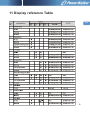
1
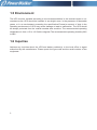
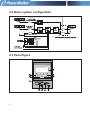
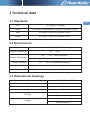
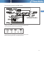
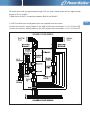
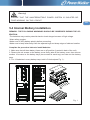
PowerWalker VFI 3/3 Series
VFI 20000TP 3/3 BE/BI
380/400/415V 50/60Hz
(3-phase input/output)
User Guide
EN
©2013 BlueWalker GmbH
All Rights Reserved
The contents of this manual are the copyright of the publisher and may not be
reproduced (even extracts) unless permission granted. Every care has been
taken to ensure the accuracy of the information contained in this manual, but
no liability can be accepted for any errors or omission. The right to make design
modifications is reserved.
User Guide UPS 20kVA B, 380/400/415V, 50/60 Hz
(3-phase input/3-phase output)
614-09943-02
Contents
1. Safety instructions….....……………………………………………………....………..
01
1.1 Safety caution….....………………….....………………….....………………….....
01
1.2 Audience caution….....………………….....………………….....………………
01
1.3 CE marking….....………………….....………………….....………………….....…
02
1.4 User precaution….....………………….....………………….....………………02
1.5 Environment….....………………….....………………….....………………….....
03
1.6 Inquiries….....………………….....………………….....………………….....……
03
2. Introduction..........................................…………………………….....………………04
2.1 System description….....………………….....………………….....………………
04
2.2 Basic system configuration….....………………….....………………….....……
05
2.3 Panel figure….....………………….....………………….....………………….....…
05
2.4 Exterior figure….....………………….....………………….....………………….....
06
3. Technical data…………………………………………….……………….....…………
08
3.1 Standards…………………………………………………………………………
08
3.2 Environment………………………………………………………………………
08
3.3 Dimensional drawings……………………………………………………………
08
3.4 Characteristics……………………………………………………………………
09
3.5 AC input……………………………………………………………………………
09
3.6 DC circuit……………………………………………………………………………
09
3.7 AC output……………………………………………………………………………
10
3.8 Battery and charger………………………………………………………………
10
11
4. Mechanical installation.….…....………………………………………………………
4.1 Delivery check………………………………………………………………………
11
4.2 Unpacking and visual inspection………………………………………………
11
4.3 Planning before installation………………………………………………………
13
4.4 Cabinet installation………………………………………………………………
14
4.5 Maintenance Bypass Switch (MBS) …………………………………………14
21
5. Electrical installation…………………………………..............………………………
5.1 Electrical Preparations……………………………………………………………
21
21
5.2 Installation and wire connection diagram………………………………………
24
5.3 Suggested cable and protective devices………………………………………
5.4 Internal Battery Installation……………………………………………………26
5.5 Connecting the external battery………………………………………………29
30
5.6 Connections between battery cabinet and UPS………………………………
5.7 Handling the batteries……………………………………………………………
31
6. Software and connectivity……………………………………………………………
32
35
7. User operations………………………………………………………………………
7.1 Single machine operation………………………………………………………
35
7.2 Parallel machine operation………………………………………………………
43
46
8. Maintenance……………………………………………………………………………
8.1 Battery Maintenance………………………………………………………………
46
8.2 Regular service/intervals…………………………………………………………
48
8.3 Cooling fan…………………………………………………………………………
48
9. Parallel systems…………….…………………………………………………………
49
10. Recycling the used UPS or battery……………………………………………… 51
52
11. Display reference Table………………………………………………………… …
EN
1 Safety instructions
This user manual contains important safety instructions and operating instructions. Please
read the user manual carefully before operating or working on the UPS and save it for reference in the future.
1.1 Safety caution
The UPS operates with external AC mains, battery cabinet(s) or bypass power. It contains
components that carry hazardous voltages and high currents, The properly installed enclosure is earthed and IP20 rated against electrical shock and foreign objects. The user is not
permitted to open it. Failure to observe this could result in electric shock risk.
Only qualified personnel is allowed to install and service the UPS.
Warning!
Operations inside the UPS must be performed by a service engineer from the manufacturer or from an agent authorised by the manufacturer.
Use the optional Maintenance Bypass Switch (MBS) for service inside the UPS when installed to the system. Remember to open battery cabinet(s) breaker. Always ensure by measuring with a multimeter that no dangerous voltages are present. For detailed MBS operation instructions please see 4.5.
1.2 Audience caution
The intended audiences of this manual are people who plan the installation, install, commission, and use or service the UPS. The manual provides guidelines to check delivery,
installing and commissioning of the UPS. The reader is expected to know the fundamentals
of electricity, wiring, electrical components and electrical schematic symbols. This manual is
written for a global reader.
1
Caution!
Read the manual before operating or working on the UPS.
EN
1.3 CE marking
The product has the CE marking in compliance with the following European directives:
LVD Directive (Safety)
2006/95/EEC
EMC Directive
2004/108/EEC
Note!
This product for commercial and industrial application in the second environment Installation restrictions or additional Measures may be needed to prevent disturbances.
1.4 User precaution
The only user operations permitted are:
Start up and shut down the UPS, excluding the commissioning start-up.Use of the LCD control panel and Emergency Power Off (EPO) switch.Use of optional connectivity modules and
their software.The user must follow the precautions and only perform the described operations.Any deviations from the instructions could be dangerous to the user or cause accidental load loss.
Warning!
The user is not permitted to open any screws excluding connectivity plates and the
Emergency Power Off (EPO) switch. Failure to recognise the electrical hazards could
prove fatal.
2
1.5 Environment
The UPS must be installed according to the recommendations in this manual.Under no circumstances the UPS should be installed in an airtight room, in the presence of flammable
gases, or in an environment exceeding the specification.Excessive amount of dust in the
operating environment of UPS may cause damage or lead to malfunction. The UPS should
be always protected from the outside weather and sunshine. The recommended operating
temperature is from +15 to +20 Celsius degrees.The recommended operating humidity:20%
to 90%.
1.6 Inquiries
Address any inquiries about the UPS and battery cabinet(s) to the local office or agent
authorized by the manufacturer. Please quote the type code and the serial number of the
equipment.
3
2 Introduction
The product described in this manual is an Uninterruptible Power Supply (UPS). It is a true
online, continuous duty, double conversion, solid state, three-phase system, providing conditioned and uninterruptible AC power to protect the end-user's load.
2.1 System description
PowerWalker VFI 3/3 Series products are high-efficiency and high-performance, double
conversion, pure-online and three phase input and three phase output UPS, with unit
capacity ranging between 20KVA-40KVA. Categorized by capacity, the products can be
further divided into 20KVA, 30KVA and 40KVA. This series not only provides perfect solution for power source protection and successfully solves problems such as blackout, boost,
brownouts, sags, decaying, oscillation, high voltage impulse, voltage fluctuations, surges,
harmonic distortion, disturbances, frequency fluctuation etc, but also enhances adaptability
to complicated working environments so that the application fields is well extended to computer equipments, communication equipments and other controlling equipments with good
adaptability to complicated industrial environments as well. Therefore, this series products
can be applied in a diversified multi-industries field such as telecommunications, financing,
transportation, government, manufacturing and energy sectors.
PowerWalker VFI 3/3 Series products are also capable of ECO mode. ECO mode means
UPS load is powered by bypass AC supply while in case of abnormal AC supply the load
will be supplied by accumulator battery after conversion through inverter. As the energy
conversion efficiency reaches as high as 98% and transfer time less than 10ms under ECO
mode when there is normal AC supply, the energy saving effect of UPS is remarkable.
Remark: ECO mode is applicable only to single unit.
4
EN
2.2 Basic system configuration
2.3 Panel figure
5
① AC: This light and inverter light will turn "green" when UPS is powered by Rectifier Input;
② Inverter: This light will turn "green" when UPS load is through the inverter;
③ Battery: This light will turn "yellow" when UPS is powered by batteries;
④ Bypass: This light will turn "green" when UPS load is powered by Bypass Input;
⑤ Fault: If the UPS worked under fault condition,this light would turn on and stay “red” with
continuous warning tone being given off in case of UPS abnormal function;or flash “red” with
intermittent warning tone being given off.
⑥ LCD: Display UPS commands.
:Confirm/Enter; press this button to select a menu or confirm an operation.
⑦
:PageDown; press this button to switch to next screen display under the same menu.
⑧
⑨ :PageUp; press this button to return to next screen display under the same menu.
⑩ Esc: Escape; press this button to return to previous menu or cancel a certain operation.
Remark: Refer to Chapter 12 for detailed information of LED in accordance with UPS
condition.
2.4 Exterior view
Exterior figure of PowerWalker VFI 20000TP 3/3 BE/BI UPS
LCD panel
PARALLEL
Intelligent slot
Extended slot
SERVICE
AS400
EPO
RS485
RS232
Button
LED indicator
light
Fan
Front view
Rear view
6
EN
CHGR FAN
Battery trays
Front view(door open)
7
3 Technical data
3.1 Standards
EN
UPS
VFI 20000TP 3/3 BE/BI
Safety
IEC62040-1:2008,EN62040-1:2003 and EN60950-1:2005
EMC
IEC62040-2:2006 and EN62040-2:2005
Product
IEC62040-3:1999 and EN62040-3:2001
3.2 Environment
UPS
VFI 20000TP 3/3 BE/BI
Working Temperature
0℃ ~ +40℃
-30℃ ~ +65℃ (without batteries)
Storage Temperature
0℃ ~ +40℃ (with batteries)
Relative Humidity
5% ~ 90%, no condensation allowed
Altitude derating coefficient
Vibration
See user operations section for more detail information
IEC68-2-6; max. 0.3mm (2 to 9Hz), max. 1m/s2 (9 to 200Hz) sinusoidal
3.3 Dimensional drawings
UPS
VFI 20000TP 3/3 BE/BI
Width
420mm
Depth
700mm
Height
1245mm
N.W(Kg)
G.W(Kg)
120(without batteries)
272(with batteries)
172(without batteries)
324(with batteries)
8
3.4 Characteristics
VFI 20000TP 3/3 BE/BI
Efficiency-nominal load
Up to 92%
Noise (ISO 7779)
<57dB at 75% load
3.5 AC input
VFI 20000TP 3/3 BE/BI
Rectifier input
3 phases + N
Bypass input
3 phases + N
Voltage (L-N)
121V-274 Volts without using battery
Frequency
40-70 Hz
Power factor
0.99
Input distortion
< 5% THD(I)
Rated input voltage
380V/400 V/415V
Rated input current
29A/28A/27A
3.6 DC circuit
Battery number
Battery nominal voltage
Cut off voltage
Battery charging current (A)
9
2×15
Positive battery
+180V DC
Negative battery
-180V DC
144±2V DC(when load > 2kw)
165±2V DC(when load ≤ 2kw)
±4.5A
3.7 AC output
VFI 20000TP 3/3 BE/BI
Active power
16KW
Number of phases
3-phases + N
Frequency
50/60HZ
Voltage (L-N)
Overload
capability
(Mains
available)
Overload
capability
(battery
available)
EN
220/230/240 VAC
110%<Load<=125%
10 minutes minimum,
then transfer to bypass and alarm
125%<Load<=150%
1 minutes minimum,
then transfer to bypass and alarm
Load>150%
0.5 seconds minimum,
then transfer to bypass and alarm
110%<Load<=125%
10 minutes minimum,
then transfer to bypass and alarm
125%<Load<=150%
1 minutes minimum,
then transfer to bypass and alarm
Load>150%
0.5 seconds minimum,
then transfer to bypass and alarm
3.8 Battery and Charger
Internal battery package
Dimensions
Panasonic LC-RW1245W
Strings
Stored energy time
Restored energy time
Initial Charging Current
Battery Leakage
Battery protection
Max discharging current
94*151*65/pc
2 x 15
Up to 580s
<5Hours
Charger Input Protection
Rated Charge Voltage
CSB HR1234WF2
94*151*64.5/pc 2 x 15
At Rated linear Load , 25℃
Up to 90% charge
8 A fuse
±202V
Default for Integrated battery
4.5A
< 3.5mA
30A Fuse*3
For PCBA level
100A Fuse For internal battery
62A Ubat=288VDC, Full RCD load
10
4 Mechanical installation
The UPS and accessories are delivered on a specifically designed pallet that is easy to
move with a forklift or a pallet jack. Keep the UPS always in upright position and do not drop
the equipment. Do not stack the pallets.
4.1 Delivery check
The UPS is delivered with the following items:
1. Winpower disc
2.RS-232 serial cable
3.User Guide
4.Key
5.Battery kit(wires & trays)(only for models without batteries)
4.2 Unpacking and visual inspection
Check that there are no signs of shipping damages. The equipment should be transported in
the upright position.
Note!
A claim for shipping damage must be filed immediately and the carrier must be informed within 7 days of receipt of the equipment. The packing materials should be
stored for further investigation.
Unpack the equipment by removing the packing and shipping materials. Make a visual
inspection. Remove the equipment from the pallet and make sure that the floor surface is
solid and suitable for the wheeling and heavy weight.
Remove cover plate → Remove side plate → Remove stuffing and fix
11
EN
Check the information on the type designation label of the equipment to verify that the unit is
of the correct type. The type designation label includes ratings, a CE marking, a type code,
a part number and a serial number. The serial number is important when making inquiries. It
allows individual recognition of the equipment.
12
4.3 Planning before installation
The equipment must be installed in upright position. The equipment requires space to front
and back to enable cooling airflow. Service and maintenance require more than 40cm clearance on right hand side. All cooling air enters at front and exits at unit rear. The required
minimum clearance from unit rear to an obstruction is 50cm. Because the service and user
access is in the front there should be reserved enough space (min 60cm).
Preparation for installation.
1. Avoid extremes of ambient temperature; excessive dust, moisture or vibration; flammable
gases; and corrosive or explosive atmospheres.
2.Altitude for normal UPS function should not exceed 1000m.
3.The battery cabinet should work within a temperature range from15℃ to 25℃ .
4.The maximum ambient temperature for normal UPS performance should not exceed
40℃ .
13
4.4 Cabinet installation
The required distance for UPS units should allow for service access. The same applies to
the battery cabinet(s) that should be installed next to the UPS cabinet(s).
EN
Caution!
UPS cabinet(s) can fall over if the installation brake pads are not used. Both rear and
front pads must be used to secure the UPS cabinet to the floor.
Use a 19mm wrench in clockwise direction to screw the brake pad down to the ground,
keeping the machine from moving.
4.5 Maintenance Bypass Switch(MBS)
Warning!
All operations inside the unit must be performed only by a service engineer from the
manufacturer or from an agent, authorised by the manufacturer.
The operation of the MBS is allowed for a service engineer from the manufacturer or from
an agent, authorised by the manufacturer. The full UPS wiring diagram with a MBS switch is
presented in the installation part of the manual.
14
The switching sequence for circuit breaker from normal position to maintenance position:
The normal positions of the MBS switches.
15
The maintenance positions of the MBS switches
EN
Transfer UPS from normal mode to maintenance bypass mode:
1.The normal start position should be following:
2.Use LCD to turn the UPS from normal mode to bypass mode:
Switch-off action (press ESC to exit above picture)
16
1)Switch-off picture
2)If it is in single machine mode, the
following will appear
Remember to verify the transfer before proceeding the next step.
3.Remove the locking plate of maintenance switch.
4.Turn OFF the Rectifier Input switch and battery fuse.
5.Turn the Maintenance switch to “MAINTENANCE” side.
6.Turn OFF the Bypass Input switch and N switch.
17
7.UPS is now in the maintenance bypass mode, see below (Note: the Serv disconnect i.e.
battery fuse must be turned off):
EN
Transfer UPS from maintenance bypass mode to normal mode:
1.The normal start position should be following:
2.Turn ON the Bypass Input switch and N switch
When the LED of bypass turns green,the UPS enters into bypass mode.
3.Turn the Maintenance switch to “UPS” side.
18
Then the UPS turn to bypass mode.
4.Turn ON the Rectifier Input switch and battery fuse.
5.Use LCD to turn the UPS from bypass mode to normal mode:
Switch-off action (press ESC to exit above picture)
1)Switch-on picture
19
2)Press ENTER
6.UPS is now in the normal mode,see below:
EN
7.Remount the locking plate of maintenance switch to the position to prevent the use of it.
20
5 Electrical installation
5.1 Electrical Preparations
Note!
It must be ensured that no line input source can accidentally be connected to the UPS
during installation.
Warning!
Installation may only be carried out by qualified technicians and in conformity with the
applicable safety standards.
Warning!
The UPS unit is not applicable to the IT power distribution system.
5.2 Installation and wire connection diagram
The UPS unit has the following power connections:
Three-phase (L1, L2, L3), Neutral (N) and Protective Earth (PE) connection for the rectifier
input.
Three-phase (L1, L2, L3), Neutral (N) and Protective Earth (PE) connection for the bypass
input ( N is INTERNALLY common for rectifier and bypass inputs).
Three-phase (L1, L2, L3), Neutral (N) and Protective Earth (PE) connection for the load
output.
Positive pole (+),Negative pole (-), Common midpoint/Neutral pole and Protective Earthing
(PE) connection for the external batteries.
24 red wires with an approximate length of 8 cm and 2 red wires with an approximate length
of 30 cm for BAT+.
7 red wires for BAT+ connection between Shelf 1 and Shelf 2; 4 blue wires for BAT N inside
Shelf 3.
21
24 black wires with an approximate length of 8 cm and 2 black wires with an approximate
length of 30 cm for BAT-.
7 black wires for BAT- connection between Shelf 4 and Shelf 5.
1.If UPS rectifier input and bypass input are supplied from two mains:
Connect the mains 1 supply cables to the UPS rectifier input terminals L1, L2, L3, N and PE.
Connect the mains 2 supply cables to the UPS bypass input terminals L1, L2, L3, N and PE.
22
EN
2.If UPS rectifier input and bypass input are supplied from one mains only:
Connect the mains supply cables to the UPS rectifier input terminals L1, L2, L3, N and PE .
The following three jumpers must be fixed between the rectifier and bypass input terminals:
L1-L1, L2- L 2, L3- L3.
Terminal block diagram
Warning!
High touch current earth connection essential
23
before connecting supply.
In order to gain access to the external electrical connections it is necessary to remove the
front terminal protective panel of the UPS. Before the cables are connected they shall be
passed through the cable glands to hold them in position and tightened.
Connect the Protective Earthing (PE) cable first.
Connect other cables as shown in the connection terminal representations on the preceding
and following pages.
Ensure that the UPS is isolated before removing front terminal protective panel.
5.3 Suggested cable and protective devices
Caution!
All cables should always use copper cable type.
The conductor cross sections apply for maximum currents:
(1) For PVC-insulated copper cables (at 70℃ )
(2) When routed in conduits for electrical installations
(3) When air temperature surrounding the conduits does not exceed 30℃
(4) For cable lengths up to 30 m
Notice!
Should there be any variation in the conditions it will be necessary to verify whether
the cable dimensions satisfy the requirements of IEC-287 and DIN VDE 0298. In cases
where the cables are so long that they cause a drop in voltage of >3%, a larger dimension shall be selected.
Routing of communication cables or data lines should be kept separate from the UPS input,
output, and external battery cables.
24
EN
Use cable cross section and protective device specification
Model
Rectifier Input L1, L2, L3, N,
Bypass Input L1, L2, L3, N,
min. conductor cross section[mm 2]
max. possible cross section[mm 2]
Rectifier Input L1, L2, L3, N breaker (A)
VFI 20000TP 3/3 BE/BI
6
35
60A 230VAC
Bypass Input L1, L2, L3, breaker (A)
60A 230VAC
Rectifier Input fuse (A)
60A 250VAC
Bypass Input fuse (A)
60A 250VAC
Internal battery fuse
100A 700VAC
Output L1, L2, L3, N,
min. conductor cross section[mm 2]
max. possible cross section[mm 2]
6
35
External Battery Cabinet Positive
pole(+),Neutral pole,Negative pole (-),
min. conductor cross section[mm 2]
max. possible cross section[mm 2]
10
35
External Battery Cabinet Fuse (A) in
Positive pole(+),Neutral pole,
Negative pole (-),
80A 250VDC
External Battery Cabinet breaker (A) in Positive pole(+),Neutral pole,Negative pole (-),
80A 250VDC
Backfeed protection device
Protective Earthing conductor [mm 2]
Torque for fixing above terminals
40A 250V AC Clearance
distances:>=1.4mm Break time<=15s
Max 35
2.8-3 Nm
Notice!
The following label must be displayed on all switching devices installed in the same
electrical system as the UPS, even when these are located at a distance from the area
in which it is located (according to European standard EN 62040-1-1).
25
Warning!
ENSURE THAT THE UNINTERRUPTIBLE POWER SYSTEM IS ISOLATED BEFORE WORKING ON THIS CIRCUIT.
EN
5.4 Internal Battery Installation
REMARK: THE FOLLOWING WARNINGS SHOULD BE OBSERVED DURING THE OPERATION:
-The batteries may contain potential electric shock danger because of high voltage.
-Wear safety goggles.
-Make sure to verify battery polarity before connecting.
-Make sure to keep wires away from the adjacent legs and sharp edges of shelves handles.
Complete the procedure below to install batteries:
1. Make sure that all three battery fuses are on off position (Located in back of the unit).
2. Remove the six screws on the battery cover firstly, take off the battery cover, then remove
another 10 screws on the battery trays (two screws for each tray) and take out the battery
trays.
3. Put 12 batteries in every battery trays, total is 5 shelves(see Fig .1) .
Fig. 1
26
4. Connect the cables to each shelf respectively (see Fig. 2).
Remark: make sure the cables between the shelves are disconnected and the following
wire connections are done: B1, B2, B3, B4, B5, B8, B9, B10, B11, B12, B15, B16 and other
24 black cables without labels.
Fig. 2
5. Pack the battery trays and put them into the enclosure (see Fig. 1 & Fig. 2).
6. Secure each tray with two screws.
7. Connect the cables between shelves and other two cables (B13 and B14). And then connect BATT+, BATTN and BATT- to the three existing battery bus wires correspondingly.
REMARK: MAKE SURE TO CONNECT WIRES WITH THE SAME COLOR.
8. Tie up the wires properly (see Fig. 3)
9. Reinstall the battery cover and secure it with the six screws.
27
Table1: Battery cable list
Label
Colour
B1
B2 B3 B4
B5 No label B8
B9 B10 B11 B12 B13 B14 B15 B16
Blk
Blu Red Blk Blk Red Red Blk Blk Red
24
24
1
Length(mm) 120 230 400 420 80
80
500 130 130 300 300 350 150 200 200
Quantity
Red Blk Red Blk Red
2
3
2
1
1
1
2
2
1
1
1
1
Fig. 3
28
EN
5.5 Connecting the external battery
Before connecting the external battery, please read the notice and warning label on
the UPS.
Warning!
In the event of malfunction, the battery cabinet chassis or battery cabinet frames may
become live!
Warning!
Special care should be taken when working with the battery cabinet associated with
the PowerWalker VFI 3/3 Series 20 - 40 kVA. When the battery cabinet is connected
the overall voltage exceeds 400V. It is very important to ensure that the batteries are
installed separately, in a dedicated battery cabinet.
Notice!
The most common battery type used in UPS installations is the valve regulated battery. Valve regulated cells are not sealed. The amount of gas given off is less than for
flooded cells, but when planning the battery installation, allowance must be made for
adequate ventilation and heat dissipation. Valve regulated cells are not completely
maintenace- free. They must be kept clean and their connections checked periodically
to ensure they are tight, and that there is no evidence of corrosion. It is inevitable that
the batteries will lose charge during transportation and storage; before attempting to
carry out an autonomy test, ensure that the batteries are fully charged as this may
take several hours. Cell performance typically improves after a few discharge/recharge
cycles.
29
Notice!
The requirements of the EC directives are satisfied when battery cabinet are used with
original accessories. If alternative batteries are used, you must ensure that the applicable EC directives are met and declare conformity.
EN
Connect the battery cabinet as follows:
Turn off the UPS.
Check all the three internal battery fuses are not inserted and/or any external battery switchs
open.
Connect PE first.
Connect the battery cabinet(s) with cables sized according to cable cross setion and protective device specification to terminals + (positive pole) ,- (negative pole) and Neutral pole.
Refer to instruction provided with the battery cabinet or by vendor.
Warning!
ENSURE CORRECT POLARITY!
5.6 Connections between battery cabinet and UPS
Make sure the Protective Earthing (PE) connected first.
External Battery Cabinet Connections
30
5.7 Handling the batteries
Warning!
Batteries are a potential source of danger due to their electrical charge and chemical
composition. Therefore observe the battery handling instructions of the manufacturer.
These usually can be found in the material which accompanies the shipment.
Recharging batteries
Warning!
When recharging, observe the indications on the packaging.
Exchanging batteries
Warning!
Before replacing batteries, make sure that those to be installed are fully charged.
Connecting external battery cabinet
Warning!
If a battery cabinet has been disconnected and is to be reconnected, the battery isolator may only be reconnected after you have made certain that voltage with the correct polarity is present on both sides of isolating device.
31
6 Software and connectivity
The Series provide Intelligent Slot, Expanded Slot, PARALLEL, AS400, EPO, RS485 and
RS232 as well as SERVICE Supervising Communication Interface exclusively available to
PowerWalker technical personnel.
1
3
PARALLEL
4
PARALLEL
AS400
5
EPO
7
RS485
Intelligent slot
SERVICE
RS232
Expanded slot
2
6
8
1. Intelligent slot: suitable for WebPower card of remote supervising management,enabling
you to realize remote supervising management on UPS through Internet.
2. Expanded slot: Reserved for special applications
3. PARALLEL: communication interface for parallel machine mode.
4. Standard AS400 interface: provides AS400 and users can directly use UPS supervising
function offered by AS400 system to realize power source management (See Appendix for
AS400 port Pin).
5. EPO: Emergency Power Off, providing the possibility of emergency shut down.Normally
closed.
6. Standard RS485 Interface: It can be used to monitor parallel units for completely control
of UPS (See Appendix for RS485 port Pin ).
7. SERVICE Interface: available only to PowerWalker technicians
8. Standard RS232 Interface: applicable to WinPower supervising software of graphic management (See Figure for RS232 port Pin)
32
EN
RS232 port
RS485 port
33
AS400 port
EN
Note!
The UPS have to be manually reset if remote shutdown occurs.
34
7 User operations
Warning!
High touch current earth connection essential before connecting supply.
The only user operations permitted are:
Start up and shut down the UPS, excluding the commissioning start-up.
Use of the LCD control panel and Emergency Power Off (EPO) switch.
Use of optional connectivity modules and their software.
Warning!
The user must follow the precaution, warnings and only perform the described operation. Any deviations from the user manual could be dangerous to the user or cause accidental load loss.
Should the UPS be intended for application above 1000m, progressive decrease of rated
output should be applied as listed in the following chart:
7.1 Single machine operation
1. Make sure L1, L2 and L3 phase sequences are correctly connected and then supply
power to UPS.
2.Close internal battery fuse.
3. Turn on the switch on battery box if the UPS equipped with External battery(make sure
that the “+”,“N” and “-” of terminal bay are in accordance with those on the battery box).
4. Switch on “Input Switch” (Rectifier Input Switch,Bypass Input Switch) on UPS and fans
start to rotate for UPS self-inspection. Main menu can be accessed within about 4sec and
then operations should be carried.
35
Remark: the following drawing takes PowerWalker VFI 20000TP 3/3 as an example and statistics are only for reference.
1)Power on
2)Automatic access within about 4s
EN
POWERWALKER
VFI 20000TP 3/3
3)Press ESC to access or automatically
within 1min with no button being pressed
36
4)Press ▼ to obtain the below information
36
5)Press ▼ again to obtain the below
6)Press ▼ again to obtain the below
information
information
7)Press ▼ again to obtain the below
8)Press ▼ again to obtain the below
information
information
VFI 20000TP 3/3
37
Note!
If malfunction occurs, “x” will appear at the lower right corner of the display,while a
warning occurs, “
” will appear at the same position (as illustrated in the below picture with battery mode as an example).
EN
4. Start-up action (press ESC to exit the above picture)
1)Switch-on picture
2)Press ENTER
38
3)Select “Yes, Confirm” to switch on
4)Normal Switch-on
the machine
5)Battery power supply (switch off line input switch)
39
5. Switch-off action (press ESC to exit above picture)
1)Switch-off picture
2)If it is in single machine mode, the
following will appear
EN
3)If it is in parallel machine mode, the
4)Press ENTER
following will appear
40
5)Select “Yes, Confirm” to switch off
6)Normal Switch-off
the machine
Note!
If you intend to switch off only one set of UPS among the parallel machine system, select “single machine switch-off”; if switch-off is intended for the entire parallel machine
system, select “parallel machine switch-off”.
6. Help
1)Help picture
41
2)Press ENTER on help picture
7. Configuration (press ESC to exit the above picture)
You are able to access Setting picture by using user combination (default: 1234, subject to
personal modification) so as to set the following programs.
1)Action display (bypass power supply)
2) Press ▼
3)Enter respective password
4)Select action item
EN
8. The Series is capable of DC start-up without AC input, panel display being similar to
switch-on picture with AC supply. DC switch-on and off are available by following instructions appearing in the pictures.
42
9. Procedures of DC switch-on:
Activate DC switch-on function set under UPS bypass mode
Make sure that “+”, “-” and “N” wires of batteries are properly connected to UPS
Switch on batteries
Lightly touch ENTER
Manually conduct switch-on order within about 1min after LCD self-inspection
Note!
UPS will be switched off automatically if there is no operation within 1min after LCD
self -inspection is completed!
7.2 Parallel machine operation
Redundancy introduction
N+X is currently the most reliable power supply structure, in which N indicates the minimum
UPS number required for the total load and X is the redundant UPS number, namely, the
malfunctioning UPS number that the system can simultaneously bear. The larger X is, the
higher reliability of system will be. For instance, if the total load of a customer registers
55kVA, we can use 20KVA for N+X design. With N taking up 3, X can be selected in accordance with reliability degree or cost requirement. Supposing customer selects X=2 and
equalized UPS power supply is 11kVA for each unit, when one set of UPS breaks down
with malfunction, the remaining four sets will provide power with almost 14kVA equalized
current; if two sets of UPS fail, the remaining three sets of UPS are supposed to provide
power supply with almost 18kVA equalized current. The maximum allowance of this system is for two sets of UPS going down at the same time, the chances of which are much
smaller than those of one UPS malfunction. Therefore, the reliability degree can be largely
enhanced,making it an optimal mode for application in locations where high degree of reliability is always a focus.
PowerWalker VFI 20000TP 3/3 is capable of direct parallel connection, which only requires
the parallel connection wires (optional) for 2 to 8 sets of UPS in parallel connection in order
to realize power redundancy (N+X).
43
Parallel machine wire connection drawing(one battery supply)
EN
Parallel machine wire connection drawing(separate battery supply)
44
Single machine wire connection drawing
45
8 Maintenance
Warning!
EN
The Maintenance must be performed by a service engineer form the manufacturer or
form an agent authorised by the manufacturer.
PowerWalker VFI 20000TP 3/3 requires minimum maintenance.
1. If battery is switched off, loaded equipments will not be covered for power-off protection.
2. Make sure UPS vent are properly ventilated and clean side frames and fan vents from
dusts every half a year (switch off AC, battery cabinet and internal battery fuse prior to
cleaning)
8.1 Battery Maintenance
The battery is key component of the UPS. The battery life depends on the ambient temperature, charge and discharge times. High ambient temperature and deep discharge will
shorten the battery life.
1. Sealed maintenance-free lead acid battery be used in the standard. When being connected to the utility power and if the UPS has been turned on, the UPS keeps charging the
battery and also offers the protective function of charging and discharging.
2. Keep the ambient temperature between 15℃ and 25℃ .
3. If the UPS has not been used for a long period, charging is recommended at the interval
of 3 months.
4. Normally, the battery should be charged and discharged every 4 to 6 months. Charging
should be started after the UPS shut down automatically in the course of discharging. In
the regions of hot climates, the battery should be charged and discharged every 2 months.
Moreover, the standard charging time should be no less than 10 hours.
5. It’s not recommended to replace batteries individually. Complete replacement should follow instructions given by battery suppliers.
6. Under normal conditions, the battery life lasts 3 to 5 years. Should batteries be found in
poor performance, replacement should be done as soon as possible only by qualified personnel with proper training. Users are not allowed to replace without authorization.
46
Remark:
A. Prior to battery replacement, switch off UPS and remove it from AC and battery, take off
internal battery fuse.
B. Take off metallic articles such as rings and watches.
C. Use screw drivers equipped with insulated handles and do not place tools or other metallic substances on the batteries.
D. Short circuit or reverse connection is forbidden for battery polarity connection.
The troubleshooting procedure gives simple remedial if a malfunction occurs in the UPS.
The operator should start the trouble shooting if there is an active alarm indicated on the
LCD screen. Service should be contacted if the active alarm is abnormal and displayed as a
service code.
Should maintenance prove necessary, the following steps should be followed:
1. Check if UPS input wiring is done properly.
2. Check if all air switches are tripped out.
3. Check if voltage input is within specified range
Please refer to “Light Reference Table” of this User Manual first and then conduct proper
treatment. If problems still exist, please record UPS model, serial number as well as purchase date, symptom on fault, light condition, LCD malfunction or warning information.
47
8.2 Regular service/intervals
The UPS requires very little maintenance if installed in an appropriate environment. In order
to ensure maximum availability of the UPS, manufacturer recommends signing a proactive
service agreement with a local authorised service provider.
Maintenance
Batteries change
Batteries test
Cooling fan change
Interval
3-5 years or according to battery suppliers recommendations
18 months
5 years
8.3 Cooling fan
The cooling fan lifespan of the UPS unit is about 60 000 operating hours. The actual lifespan
depends on the environment and ambient temperature.
Fan failure can be predicted by increasing noise from the fan bearings. The fan replacement
is recommended once this symptom starts appearing.
Do not use other than manufacturer’s specified spare parts.
48
EN
9 Parallel systems
Note!
Parallel is only connected to identical ports for the UPS of same models and kVA rating.
1) Follow installation instructions for general installation requirements.
2)Ventilation spacing between machines should allow for service access.
3) Input wiring for each set of UPS should follow the requirements for that of single unit.
Each UPS input should be connected to the same input patch board.
4) Each UPS output wire should be connected to the output patch board, from which wires
are distributed for load as illustrated in following figure.
Remark 1: common battery pack is applicable in parallel machine mode;
Remark 2: each battery pack should be of the same model from the same manufacturer;
Remark 3: requirement of output wiring length:
When the lead from the output terminal of each set of UPS to the output patch board is less
than 20m, wire difference should be less than 20%;
When the lead from the output terminal of each set of UPS to the output patch board is longer than 20m, wire difference should be less than 10%.
49
EN
Note!
Parallel signal cable should be connected as a loop.
50
10 Recycling the used UPS or battery
Before scrapping UPS or its battery cabinet, the battery bank must be removed. Local requirements must be followed in battery recycling or discard. The removal of batteries is allowed only by authorised service personnel due to high energy and voltage.
Do not discard waste electrical or electronic equipment in the trash. For proper disposal,
contact your local collecting/recycling/reuse or hazardous waste center and follow the local
legislation.
These symbols indicate on a product:
You can find out which recycling firm is responsible for your neighbourhood by contacting
your local authority.
Batteries must not be put in the domestic refuse either!
All consumers have a statutory duty to take all batteries to a collection point in their municipality/district or to a retail store so that they can be disposed of in an environmentallyfriendly way,regardless of whether they contain toxic substances.
All batteries should be fully discharged before they are returned for disposal.
PROTECTION OF THE ENVIRONMENT/DISPOSAL OF THE EQUIPMENT.
Do not on any account put your old equipment out with the domestic refuse.
For the sake of the environment,please use your local authority’s collection point set to return and recycle old electric and electronic equipment.
51
11 Display reference Table
EN
52
Should any display or warning message excluded in the above table be found,please contact distributor or call PowerWalker Hot line for advice.
● Indicator light is on
★ Indicator light flashes
Warning include one or more than one of these:
1.EPO active
11.Charger failure
2.Line loss
12.Battery over restrict
3.Neutral loss
13.Battery over temperature
4.Line phase error
14.Fan over restrict
5.Bypass loss
15.BUS capacitor over restrict
6.Bypass phase error
16.Fan failure
7.Battery open
17.Fan disconnected
8.Low battery voltage
18.Low temperature Battery
9.Over charger
19.communication disconnected
10.Battery reverse
20.Auxiliary charger failure
53
614-01718-00