1
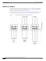
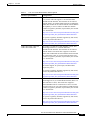
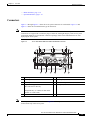
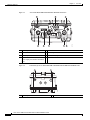
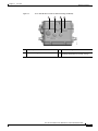
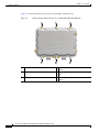
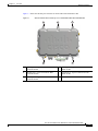
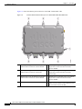
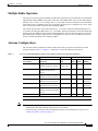
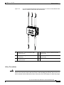
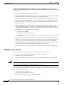
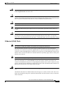
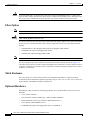
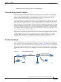
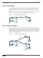
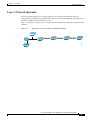
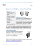
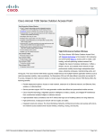
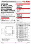
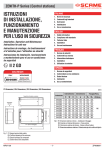
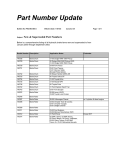
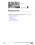
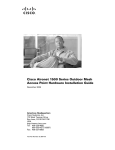
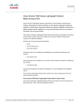
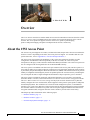
CHAPTER
1
Overview
The Cisco Aironet 1550 Series Outdoor Mesh Access Point for Hazardous Locations (hereafter called
the access point or AP) is a modularized wireless outdoor access point designed for use in a mesh
network. The access point also supports wireless client access, point-to-point bridging,
point-to-multipoint bridging, and point-to-multipoint mesh wireless connectivity.
About the 1552 Access Point
The 1552 access point supports two radios (2.4-GHz and 5-GHz) and provides client access without the
need for a license. Depending on the radio, the access point can support 1 to 300 Mb/s data rates (for
specific data rates, refer to Appendix D, “Access Point Specifications”).
The 1552 access point supports the modularity of the 1520 series and allows flexibility in radio
configuration. In addition to full interoperability with 802.11n clients, the 1552 access point
interoperates with legacy clients and offers enhanced backhaul performance. The 1552 access point can
also be configured with an integrated ISA 100 or WirelessHART Gateway.
The access point is a standalone unit that can be pole mounted. The access point can also operate as a
relay node for other access points not directly connected to a wired network. Intelligent wireless routing
is provided by the patented Adaptive Wireless Path Protocol (AWPP). This enables each access point to
identify its neighbors and intelligently choose the optimal path to the wired network by calculating the
cost of each path in terms of signal strength and the number of hops required to get to a controller.
The access point is configured, monitored, and operated through a Cisco wireless LAN controller
(hereafter called a controller) as described in the Cisco Wireless LAN Controller Configuration Guide.
The Cisco Wireless Mesh Access Points, Design and Deployment Guide describes how to plan and
initially configure the Cisco mesh network, which supports wireless point-to-point, point-to-multipoint,
and mesh deployments. The controllers use a browser-based management system, a command-line
interface (CLI), or the Cisco Wireless Control System (WCS) network management system to manage
the controller and the associated access points. The access point supports hardware-based advanced
encryption standard (AES) encryption between wireless nodes to provide end-to-end security.
This chapter provides information on the following topics:
•
Hardware Models, page 1-2
•
Hardware Features, page 1-4
•
Network Deployment Examples, page 1-17
Cisco Aironet 1550 Series for Hazardous Locations Installation Guide
1-1
Chapter 1
Overview
Hardware Models
Hardware Models
The model numbers (or part numbers) and configuration for the Cisco Aironet 1552 Outdoor Mesh
Access Points for Hazardous Locations are described in Table 1-1. A detailed list of components
supported by each 1552 access point model is shown in Table 1-2.
For a detailed description of the declarations of conformity and regulatory information for the 1552
access points refer to Appendix B, “Declarations of Conformity and Regulatory Information.”
Figure 1-1
1552 Access Points for Hazardous Locations Spotters Guide
Cisco Aironet 1550 Series for Hazardous Locations Installation Guide
1-2
Chapter 1
Overview
Hardware Models
Table 1-1
1552 Access Point Model Numbers and Descriptions
Model (or part number)
Configuration
AIR-CAP1552H-x-K9
Two-radio (2.4 GHz and 5 GHz) Hazardous Location (Haz
Loc) version. This AP supports 3 external dual-band
omnidirectional antennas. The antennas can be ordered
with the model. An optional Small Form Factor Pluggable
(SFP) fiber module can be ordered with the AP. The AP has
the capability to receive and use an SFP fiber module.
Countries (regulatory domains) represented by the variable
x are described at:
http://www.cisco.com/en/US/prod/collateral/wireless/ps56
79/ps5861/product_data_sheet0900aecd80537b6a.html
For specific regulatory domains supported by this model,
refer to the product data sheet at:
http://www.cisco.com/en/US/prod/collateral/wireless/ps56
79/ps5861/product_data_sheet0900aecd80537b6a.html
AIR-CAP1552SA-x-K9 and
AIR-CAP1552SD-x-K9
Two-radio (2.4 GHz and 5 GHz) modular version. This
model supports three (3) external dual-band
omnidirectional antennas. The antennas can be ordered
with the model. This model also supports two ISA100
radios with 2 additional external omnidirectional antennas
for connections to 802.15.4 sensor network transceivers.
Countries (regulatory domains) represented by the variable
x are described at:
http://www.cisco.com/en/US/prod/collateral/wireless/ps56
79/ps5861/product_data_sheet0900aecd80537b6a.html
SA models support AC power input, and SD models
require DC power.
For specific regulatory domains supported by this model,
refer to the product data sheet at:
http://www.cisco.com/en/US/prod/collateral/wireless/ps56
79/ps5861/product_data_sheet0900aecd80537b6a.html
AIR-CAP1552WU-x-K9
Two-radio (2.4 GHz and 5 GHz) modular version. This
model supports six (6) external WiFi antennas (Three 2.4
GHz and Three 5 GHz). This model also supports a
WirelessHART radio for connections to 802.15.4 sensor
network transceivers via a cable-attached 2.4 GHz antenna.
Countries (regulatory domains) represented by the variable
x are described at:
http://www.cisco.com/en/US/prod/collateral/wireless/ps56
79/ps5861/product_data_sheet0900aecd80537b6a.html
For specific regulatory domains supported by this model,
refer to the product data sheet at:
http://www.cisco.com/en/US/prod/collateral/wireless/ps56
79/ps5861/product_data_sheet0900aecd80537b6a.html
Cisco Aironet 1550 Series for Hazardous Locations Installation Guide
1-3
Chapter 1
Overview
Hardware Features
Table 1-2
Components of Each 1552 Access Point Model
1552H
1552SA/1552SD
1552WU
Antennas
External
External
External
Fiber SFP
Yes
Yes
No
PoE-Out Port1
802.3af (For example, an IP video
camera or VOIP Phone)
Yes
Yes
Yes
Cable Modem
DOCSIS 3.0
Euro DOCSIS 3.0
No
No
No
HazLoc
Class 1 Div2/Zone2
Yes
Yes
Yes
Battery Backup Option
No
No
No
SA Model: AC
24VDC
Power Options
AC, PoE
2
SD Model: 24V
DC
1.
When a 1552H is powered with PoE, the PoE-Out port is not active.
2,
PoE-In is not 802.3af; it does not work with a PoE 802.3af-capable Ethernet switch. It requires the dedicated Power Injector
(AIR-PWRINJ1500-2=).
3.
All models support 12 VDC power input for use in non-hazardous locations only.
Regulatory Domains
The “-x” in the 1552 model numbers represent the domain. For example, in AIR-CAP1552H-x-K9 the
-x represents a regulatory domain for a specific country.
For specific regulatory domains supported by each 1552 access point model, refer to the Wireless LAN
Compliance Status at:
http://www.cisco.com/en/US/prod/collateral/wireless/ps5679/ps5861/product_data_sheet0900aecd805
37b6a.html
To locate the 1552 access point models, click on 802.11abgn Mesh Access Points.
Hardware Features
This section describes the hardware features of the 1552 access point models. The following hardware
features are described in this section:
•
Connectors, page 1-5
•
Multiple Radio Operation, page 1-11
•
Antenna Configurations, page 1-11
•
Multiple Power Sources, page 1-14
•
Ethernet (PoE) Ports, page 1-15
•
Fiber Option, page 1-16
Cisco Aironet 1550 Series for Hazardous Locations Installation Guide
1-4
Chapter 1
Overview
Hardware Features
•
Metal Enclosure, page 1-16
•
Optional Hardware, page 1-16
Connectors
Figure 1-2 through Figure 1-5 show the access point connectors for each model. Figure 1-6 and
Figure 1-8 show the external antenna Type-N connectors.
Note
The illustrations in this document show all available connections for the access point. Unused
connections are capped with a connector plug to ensure the watertight integrity of the access point.
Liquid-tight adapters are provided for connector openings, which can be installed before or after
deploying the access point.
Figure 1-2
Access Point Model AIR-CAP1552H-x-K9 Bottom Connectors
1
2
5
6
282137
4
3
9
Note
8
6
7
5
4
1
Antenna port 4
6
Fiber port (PG 13.5)
2
Antenna port 5
7
PoE-out port (PG 13.5)
3
Antenna port 6
8
LEDs (Status, Up Link, RF1, RF2)
4
AC power entry port for model
AIR-CAP1552H-x-K9 only
or
Cablegland entry (1/2-NPT) for data cable
(outdoor cat 5 STP cable)
9
PoE-in port (PG 13.5)
5
Not used
Antenna ports 1, 2, and 3 are not shown in Figure 1-2. These ports are reserved for future use and are
located on the top of the access point.
Cisco Aironet 1550 Series for Hazardous Locations Installation Guide
1-5
Chapter 1
Overview
Hardware Features
Access Point Model AIR-CAP1552SA/SD-x-K9 Bottom Connectors
1
2
8
7
3
6
5
1
Antenna port 4 (ISA100.11a)
5
Not used
2
IR window
6
PoE-out port
3
Antenna port 6 (ISA100.11a)
7
LEDs (Status, Up Link, RF1, RF2)
4
AC (1552SA) or 24 VDC (1552SD) 8
power input port and fiber backhaul
port
Figure 1-4
Ethernet
Console Port for Access Point Model AIR-CAP1552H-x-K9 and AIR-CAP1552SA/SD-x-K9
2
282138
1
1
Console port
Cisco Aironet 1550 Series for Hazardous Locations Installation Guide
1-6
4
331096
Figure 1-3
2
Not used
Overview
Hardware Features
Figure 1-5
Access Point DC Power Connector and Ground Lug (All Models)
1
2
3
4
331098
Chapter 1
1
DC power port
3
Bracket mounting hole
2
Bracket mounting hole
4
Ground lug location (connection for earth
grounding (minimum VD 16 mm, 6 awg)
Cisco Aironet 1550 Series for Hazardous Locations Installation Guide
1-7
Chapter 1
Overview
Hardware Features
Figure 1-6 shows the antenna port locations for model AIR-CAP1552H-x-K9.
External Antenna Port Locations for Access Point Model AIR-CAP1552H-x-K9
3
2
1
6
5
4
255247
Figure 1-6
1
Not used
4
Antenna port 6- Type N connector 2.4/5GHz
Tx/Rx
2
Not used
5
Antenna port 5 - Type N connector 2.4/5GHz
Rx
3
Not used
6
Antenna port 4- Type N connector 2.4/5GHz
Tx/Rx
Cisco Aironet 1550 Series for Hazardous Locations Installation Guide
1-8
Overview
Hardware Features
Figure 1-7 shows the antenna port locations for model AIR-CAP1552SA/SD-x-K9.
Figure 1-7
External Antenna Port Locations for Access Point Model AIR-CAP1552SA/SD-x-K9
3
2
1
331878
Chapter 1
5
4
1
Antenna port 1- Type-N connector WiFi
2.4/5GHz TX/RX
4
Antenna port 6- Type N connector ISA100
2.4GHz Tx/Rx
2
Antenna port 2- Type-N connector WiFi
2.4/5GHz TX/RX
5
Antenna port 4- Type N connector SA100
2.4GHz Tx/Rx
3
Antenna port 3- Type-N connector WiFi
2.4/5GHz TX/RX
Cisco Aironet 1550 Series for Hazardous Locations Installation Guide
1-9
Chapter 1
Overview
Hardware Features
Figure 1-8 shows the antenna port locations for model AIR-CAP1552WU-x-K9.
Figure 1-8
1
2
3
External Antenna Port Locations for Access Point Model AIR-CAP1552WU-x-K9
Antenna port 1 Type N connector Single Band 4
5 GHz Omnidirectional WiFi Antenna TX/RX
Antenna port 4 (optional)- Type N connector
Antenna port 2 Type N connector Single Band 5
5 GHz Omnidirectional WiFi Antenna RX
Antenna port 5 (optional)- Type N connector
Antenna port 3 Type N connector Single Band 6
5 GHz Omnidirectional WiFi Antenna TX/RX
Antenna port 6 (optional)- Type N connector
7
WirelessHART Antenna port - Type N
connector Single Band 2.4 GHz Omnidirectional
WirelessHART Antenna TX/RX
Cisco Aironet 1550 Series for Hazardous Locations Installation Guide
1-10
Single Band 2.4 GHz Omnidirectional WiFi
Antenna TX/RX
Single Band 2.4 GHz Omnidirectional WiFi
Antenna RX
Single Band 2.4 GHz Omnidirectional WiFi
Antenna TX/RX
Chapter 1
Overview
Hardware Features
Multiple Radio Operation
The 1552 access point supports simultaneous dual-radio operation using a 2.4-GHz 802.11b/g/n multiple
input/multiple output (MIMO) radio and a 5-GHz 802.11a/n MIMO radio. The 2.4 GHz radio supports
channels 1 to 11 in US, 1 to 13 in Europe, and 1 to 13 in Japan. It has two transmitters with a maximum
total output power of 25 dBm for 802.11b/g/n operation. Output power is configurable to 5 levels. It has
three receivers that enable maximum-ratio combining (MRC).
The 5-GHz radio operates in the UNII-2 band (5.25 – 5.35 GHz), UNII-2 Extended/ETSI band (5.47 –
5.725 GHz), and the upper ISM band (5.725 – 5.850 GHz). It has two transmitters with a maximum total
output power of 26 dBm for UNII-2 and Extended/ETSI bands. The total maximum output power for the
upper ISM band is 28 dBm. Output power is configurable for 5 power levels in 3 dB steps. The three
receivers enables maximum-ratio combining (MRC).
Antenna Configurations
The 1552SA/1552SD, 1552H and 1552WU models must always be operated with all the external
antennas attached. Figure 1-6, Figure 1-7, and Figure 1-8show the antenna port locations.
Table 1-3
Cisco Aironet Dual-Band Omnidirectional Antenna Supported Models and configuration information
Number of Antennas
1552H
1552SA/
1552SD
Part Number
Description
Gain
1552WU
AIR-ANT2547V-N-HZ
Dual Band 2.4/5 GHz
Omnidirectional WiFi Antenna
2.4 GHz: 4 dBi 3
AIR-ANT2450V-N-HZ
Single Band 2.4 GHz
Omnidirectional ISA100
Antenna
5 dBi
AIR-ANT2480V-N
Single Band 2,4 GHz
Omnidirectional WiFi Antenna
8 dBi
3
AIR-ANT5180V-N
Single Band 5 GHz
Omnidirectional WiFi Antenna
8 dBi
3
(Optional*)
AIR-ANT5114P2M-N=
Single Band 5 GHz Directional
Dual Polarized Patch Antenna
14 dBi
1
(Optional*)
(Supplied)
Single Band 2.4 GHz
Omnidirectional WirelessHART
Antenna
3
5 GHz: 7 dBi
2
1
* One of the two optional antenna configurations must be installed for 5 GHz operation.
Note
•
The WirelessHART Antenna must be installed a minimum of 3 feet from any other antenna,
including the other WiFi antennas attached to the Access Point.
•
Follow all safety precautions when installing the antennas. For information on safety, refer to
“Safety Precautions” section on page 1-13.
Cisco Aironet 1550 Series for Hazardous Locations Installation Guide
1-11
Chapter 1
Overview
Hardware Features
Cisco Aironet Dual-Band Omnidirectional Antenna - Installed on Model AIR-CAP1552H-x-K9
282145
Figure 1-9
1
2
3
1
Antenna connected to antenna port 1 (Type-N connector) (WiFi TX/RX)
2
Antenna connected to antenna port 2 (Type-N connector) (WiFi RX)
3
Antenna connected to antenna port 3 (Type-N connector) (WiFi TX/RX)
Cisco Aironet 1550 Series for Hazardous Locations Installation Guide
1-12
Chapter 1
Overview
Hardware Features
Figure 1-10
Cisco Aironet Dual-Band Omnidirectional Antenna and Cisco Aironet 2.4 GHz Omnidirectional
Antenna - Installed on Model AIR-CAP1552SA/SD-x-K9
2
3
331099
1
4
5
1
Antenna port 1- Type-N connector WiFi
2.4/5GHz TX/RX
4
Antenna port 6- Type N connector ISA100
2.4GHz Tx/Rx
2
Antenna port 2- Type-N connector WiFi
2.4/5GHz RX
5
Antenna port 4- Type N connector ISA100
2.4GHz Tx/Rx
3
Antenna port 3- Type-N connector WiFi
2.4/5GHz TX/RX
Safety Precautions
Warning
Do not locate the antenna near overhead power lines or other electric light or power circuits, or
where it can come into contact with such circuits. When installing the antenna, take extreme care
not to come into contact with such circuits, as they may cause serious injury or death. For proper
Cisco Aironet 1550 Series for Hazardous Locations Installation Guide
1-13
Chapter 1
Overview
Hardware Features
installation and grounding of the antenna, please refer to national and local codes (e.g. U.S.:
NFPA 70, National Electrical Code, Article 810, Canada: Canadian Electrical Code, Section 54).
Statement 280
For your safety, read and follow these safety precautions.
1.
Before you install an antenna, contact your Cisco account representative to explain which mounting
method to use for the size and type of antenna that you are about to install.
2.
Select your installation site with safety, as well as performance, in mind. Remember that electric
power lines and phone lines look alike. For your safety, assume that any overhead line can kill you.
3.
Contact your electric power company. Tell them your plans and ask them to come look at your
proposed installation.
4.
Plan your installation carefully and completely before you begin. Each person involved in an
installation should be assigned to a specific task and should know what to do and when to do it. One
person should be in charge of the operation to issue instructions and watch for signs of trouble.
5.
When installing your antenna, follow these guidelines:
– Do not use a metal ladder.
– Do not work on a wet or windy day.
– Do dress properly—wear shoes with rubber soles and heels, rubber gloves, and a long-sleeved
shirt or jacket.
6.
If the assembly starts to drop, move away from it and let it fall. Because the antenna, mast, cable,
and metal guy wires are all excellent conductors of electrical current, even the slightest touch of any
of these parts to a power line completes an electrical path through the antenna and the installer.
7.
If any part of the antenna system should come in contact with a power line, do not touch it or try to
remove it yourself. Call your local power company to have it removed safely.
8.
If an accident should occur with the power lines, call for qualified emergency help immediately.
Multiple Power Sources
The 1550 series access point for hazardous locations supports these power sources:
Warning
•
AC power—100 to 240 VAC (model 1552H and 1552SA access points)
•
External 24 VDC (1552SD and 1552WU)
•
Power-over-Ethernet (PoE)—56 VDC power injector (AIR-PWRINJ1500-2=), on model 1552H
only
Connect the unit only to DC power source that complies with the safety extra-low voltage (SELV)
requirements in IEC 60950 based safety standards. Statement 1033
The 1552 access point for hazardous locations can be connected to more than one power source. The
access point detects the available power sources and switches to the preferred power source using the
following default prioritization:
•
AC power (1552H and 1552SA)
•
External 24 VDC (1552SD and 1552WU)
•
Power injector PoE power (1552SA/1552SD and 1552H)
Cisco Aironet 1550 Series for Hazardous Locations Installation Guide
1-14
Chapter 1
Overview
Hardware Features
Warning
This unit might have more than one power supply connection. All connections must be removed
to de-energize the unit. Statement 1028
Caution
To provide inline PoE, you must use the 1500 power injector (AIR-PWRINJ1500-2=). Other power
injectors, PoE switches, and 802.3af/at power sources cannot provide adequate power, which can cause
the access point to malfunction and cause over-current conditions at the power source.
Caution
The 1500 power injector (AIR-PWRINJ1500-2=) must be used in an indoor environment only.
Note
Caution
The Ethernet cable from the power injector to the access point (PoE-in port) must be not less than 10 ft
(3.1 m).
When the access point is installed outdoors or in a wet or damp location, the AC branch circuit that is
powering the access point should be provided with ground fault protection (GFCI), as required by
Article 210 of the National Electrical Code (NEC). (1552H and 1552SA, not for 1552SD and 1552WU)
Ethernet (PoE) Ports
Note
The 1552SA, 1552SD, and 1552WU access points do not support the PoE-In port.
The 1552 hazardous location access points support an Ethernet uplink port and a downlink port
(POE-Out). The 1552H access point also supports POE-In. The access point Ethernet ports use RJ-45
connectors (with a liquid tight adapter) to link the access point to the 10/100/1000BASE-T network. The
Ethernet cable is used to send and receive Ethernet data and to optionally supply inline 56-VDC power
from the power injector.
Note
When a 1552H access point is powered by PoE, the PoE-Out port is not active.
The access point PoE-out (10/100/1000BASE-T) port uses an RJ-45 connector to provide LAN
connectivity and IEEE 802.3af power to a single peripheral customer device, such as a camera or sensor
gateway. The PoE-out port should not be connected to a switch or hub. The Ethernet MAC addresses are
printed on the bottom of the access point under the LEDs.
Warning
To reduce the risk of fire, use only No. 26 AWG or larger telecommunication line cord. Statement
1023
The Ethernet cable must be a shielded outdoor rated Category 5e (CAT5e) or better cable. The access
point senses the Ethernet and power signals and automatically switches internal circuitry to match the
cable connections.
Cisco Aironet 1550 Series for Hazardous Locations Installation Guide
1-15
Chapter 1
Overview
Hardware Features
Caution
To provide inline PoE, you must use the 1500 power injector (AIR-PWRINJ1500-2=). Other power
injectors, PoE switches, and 802.3af/at power sources cannot provide adequate power, which may cause
the access point to malfunction and cause possible over-current conditions at the power source.
Fiber Option
Note
Warning
The 1552WU access point does not support Fiber.
Class 1 laser product. Statement 1008
The factory-orderable fiber option provides a fiber input and output capability. Fiber data is transmitted
and received over a dual-strand fiber cable, which is connected to the access point using these SFP
modules:
Note
•
100BASE-BX10-U fiber Rugged small-form factor pluggable (SFP) module
•
1000BASE-LX single-mode Rugged SFP module
•
1000Base-SX multimode Rugged SFP module
SFP modules are not hot-swappable.
The access point has one fiber connection, located on the bottom of the unit (shown on Figure 1-2) .
Client data is passed to the network controller through the fiber connection via a fiber-capable switch or
controller. Configuration information can be found in the controller configuration guide of the switch or
controller you are using.
Metal Enclosure
The access point uses a metal enclosure that can accommodate both indoor or outdoor operating
environments and an industrial temperature operating range of –40 to 131°F (–40 to 55°C). The access
point complies with NEMA 4 and IP67 requirements.
Optional Hardware
Depending on what you ordered, the following optional access point hardware may be part of your
shipment:
•
Cisco Aironet Antennas
•
Pole mount kits (AIR-ACCPMK1550=, AIR-ACCPMK1550HZM=)
•
Band installation tool for pole mount kit (AIR-BAND-INS-TL=)
•
Power injector (AIR-PWRINJ1500-2=)
•
1000BASE-LX single-mode Rugged SFP (GLC-LX-SM-RGD=)
Cisco Aironet 1550 Series for Hazardous Locations Installation Guide
1-16
Chapter 1
Overview
Hardware Features
•
1000BASE-SX multimode Rugged SFP (GLC-SX-MM-RGD=)
Network Deployment Examples
The access point is a wireless device designed for wireless client access and point-to-point bridging,
point-to-multipoint bridging, and point-to-multipoint mesh wireless connectivity. The access point
provides 5-GHz backhaul capability to link with another access point to reach a wired network
connection or to provide repeater operations for other access points.
The access point plays two primary radio roles: a root access point (RAP) or a mesh (non-root) access
point (MAP), which is the default role of all access points. When the access point has a fiber or wired
Ethernet or cable connector connection to the controller (through a switch), the radio role is called a
RAP. In order to be considered a RAP, the access point must be configured as a RAP. A RAP is a parent
node to any bridging or mesh network. A controller can support one or more RAPs, each one parenting
the same or different wireless networks. There can be more than one RAP for the same mesh network
for redundancy. RAPs and MAPs can support wireless clients on the 2.4-GHz and 5-GHz band. Client
access on 5-GHz is called universal client access.
When the access point does not have a wired Ethernet, fiber-optic, or cable connection to the controller,
the radio role is called a MAP. The MAPs have a wireless connection (through the backhaul interface)
to other MAPs and finally to a RAP with an Ethernet or cable connection through a switch to the
controller. MAPs can also have a wired Ethernet connection to a local LAN and serve as a bridge
endpoint for that LAN (using a point-to-point or point-to-multipoint bridge connection).
Wireless Backhaul
The access point supports wireless backhaul capability using the 5 GHz radio to bridge to another access
point to reach a wired network connection to a controller (see Figure 1-11). The access point connected
to the wired network is considered a RAP in this configuration. The remote access point is considered a
MAP and transfers wireless client traffic to the RAP for transfer to the wired network. Control And
Provisioning of Wireless Access Points (CAPWAP) control traffic is also transferred over this bridged
link.
Access Point Backhaul Example
(5 GHz)
(2.4 GHz and 5 GHz)
255493
Figure 1-11
Cisco Aironet 1550 Series for Hazardous Locations Installation Guide
1-17
Chapter 1
Overview
Hardware Features
Point-to-Point Bridging
The access points can be used to extend a remote network by using the 5 GHz backhaul radio to bridge
the two network segments as shown in Figure 1-12. To support Ethernet bridging, you must enable
bridging on the controller for each access point. By default this capability is turned-off for all access
points.
Wireless client access is supported; however, if bridging between tall buildings, the 2.4-GHz wireless
coverage area may be limited and possibly not suitable for direct wireless client access.
Figure 1-12
Access Point Point-to-Point Bridging Example
255495
(5 GHz)
Point-to-Multipoint Bridging
The access points can be used as a RAP to connect multiple remote MAPs with their associated wired
networks. By default this capability is turned-off for all access points. To support Ethernet bridging, you
must enable bridging on the controller for each access point. Wireless client access can be provided over
the bridging link; however, if bridging between tall buildings, the 2.4-GHz wireless coverage area may
be limited and possibly not suitable for direct wireless client access. Figure 1-13 illustrates an example
of access point-to-multipoint bridging.
Figure 1-13
Access Point to Multipoint Bridging Example
(5 GHz)
255494
(5 GHz)
Cisco Aironet 1550 Series for Hazardous Locations Installation Guide
1-18
Chapter 1
Overview
Hardware Features
Point-to-Multipoint Mesh Network
The access point is typically deployed in a mesh network configuration. In a typical mesh deployment,
one or more RAPs have a wired network connection through a switch to a controller. Other remote MAPs
without wired network connections use the backhaul feature to optimally link to a RAP that is connected
to the wired network. In the mesh network, the links between the access points are referred to as the
backhaul links.
Intelligent wireless routing is provided by the Adaptive Wireless Path protocol (AWPP). This enables
each MAP to identify its neighbors and intelligently choose the optimal path to the RAP with the wired
network connection by calculating the cost of each path in terms of signal strength and the number of
hops required to get to a controller with signal strength given priority since signal strength determines
the data rate available for backhaul.
Figure 1-14 illustrates a typical mesh configuration using MAPs and RAPs.
Figure 1-14
Typical Mesh Configuration Using Cisco 1552SA/1552SD Access Points with Sensors
WLC
RAP
Network
NCS
MAP 1
MAP 2
MAP 3
MAP 4
MAP 5
MAP 6
MAP 7
MAP 8
MAP 9
WDM
Wi-Fi Network link
332347
ISA100 Network link
The Cisco 1552SA/1552SD is a universal and multifunctional outdoor wireless mesh network that
supports not only WI-FI devices and applications, but also supports wireless field I/Os and actuators on
ISA100.11a protocol.
Cisco Aironet 1550 Series for Hazardous Locations Installation Guide
1-19
Chapter 1
Overview
Hardware Features
Along with robust and reliable Cisco Outdoor WI-FI wireless mesh, it also creates parallel Industrial
Wireless Automation Network to support field sensors and actuators running on ISA100.11a protocol.
The backbone router manages and aggregates Industrial Wireless Data and passes it over to the Cisco
Wireless Mesh backbone. Cisco Wireless Mesh carries Industrial Wireless Traffic with highest priority
(or QoS) with minimal latency and highest reliability and routes it to the Wireless Device Manager,
which is part of the Honeywell One Wireless Infrastructure Solution.
Refer to Cisco Documentation for installation, configuration, best practices and troubleshooting guides
on www.cisco.com.
Refer to Honeywell One Wireless Plant Solution documentation on www.honeywell.com for further
details.
Honeywell Backbone Router Activation Process
The following steps describe conceptual process and flow only. Refer to Honeywell’s detailed
documentation for configuration information.
Step 1
This process assumes that you have Honeywell One wireless setup installed. It includes, but is not
limited to, the Honeywell WDM and Honeywell or other compatible ISA100 sensors. The Honeywell
WDM should be configured according to Honeywell’s documentation.
Step 2
Once you have the WDM and other infrastructure configured according to Honeywell documentation,
activate the provisioning device provided by Honeywell in the WDM by connecting to the WDM USB
port according Honeywell documentation.
Step 3
Create keys on the WDM and download/transfer them on a handheld device.
Step 4
Launch provisioning application on handheld device. Point this handheld device towards the Infrared
Sensor on the 15552SA/1552SD and press activate button on the Honeywell Provisioning application.
Handheld device will transfer / communicate keys to Honeywell BBR and get status if activated
successfully.
Step 5
Same process needs to be applied for sensors to be activated and included in Industrial Wireless Sensor
Network.
Step 6
All these devices can be Configured and monitored in Honeywell WDM once they are part of wireless
network.
Cisco Aironet 1550 Series for Hazardous Locations Installation Guide
1-20
Chapter 1
Overview
Hardware Features
WirelessHART Gateway Configuration
This following information is abbreviated and is intended only to serve as a introduction. Refer to
Emerson's WirelessHART Gateway documentation for complete details.
Figure 1-15
Table 1-4
Typical Mesh Configuration Using Cisco 1552WU Access Points with Sensors
The default IP addresses for the WirelessHART Gateway are:
IP Address
Netmask
Notes
Ethernet 1
192.168.1.10
255.255.255.0
Connected to 1552WU internal interface
GigabitEthernet2
Ethernet 2
192.168.2.10
255.255.255.0
User accessible. Can be used for connecting
redundant WirelessHART Gateways.
The WirelessHART Gateway can be configured using a standard web browser and accessing the
Gateway's internal webpage URL (https://192.168.1.10). For this to work, the 1552WU must be
configured to pass traffic to the WirelessHART Gateway's IP address.
Cisco Aironet 1550 Series for Hazardous Locations Installation Guide
1-21
Chapter 1
Overview
Hardware Features
Table 1-5
Security Passwords
There are four role based user accounts for the gateway with varying levels of access. The table below
describes this access.
Role
User Name
Web Interface Access
Executive
exec
Read-only access
Operator
oper
Read-only access
Maintenance
maint
Configure HART® device settings
Configure Modbus communications
Configure Modbus register mapping
Configure OPC browse tree
Configure Active Advertising
Administrator
admin
Includes all maintenance privileges
Configure Ethernet network settings
Configure WirelessHART network settings
Set passwords
Set time settings
Set home page options
Configure custom point pages
Restart applications
Note
Each of the initial passwords for the user accounts is “default.” It is recommended, for security purposes,
that these passwords are changed. The administrator password should be appropriately noted when
changed. If it is lost, please contact Emerson Process Management for technical support.
To change the User Accounts Passwords:
Step 1
Navigate to Setup>Security>User accounts.
Step 2
Set the new password for each role based user account, and confirm.
Step 3
Click Submit.
Cisco Aironet 1550 Series for Hazardous Locations Installation Guide
1-22
Chapter 1
Overview
Hardware Features
Layer 3 Network Operation
The access points support Layer 3 network operation. Access points and controllers in Layer 3
configurations use IP addresses and UDP packets, which can be routed through large networks. Layer 3
operation is scalable and recommended by Cisco.
Figure 1-16 illustrates a typical Layer-3 wireless network configuration containing access points and a
controller.
Typical Layer 3 Access Point Network Configuration Example
148458
Figure 1-16
Cisco Aironet 1550 Series for Hazardous Locations Installation Guide
1-23
Chapter 1
Hardware Features
Cisco Aironet 1550 Series for Hazardous Locations Installation Guide
1-24
Overview