1
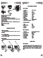
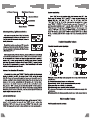
Multiple CHANNEL
WIRELESS MICROPHONE
UHF
IR /AUTOSCAN/ FREQUENCY AUTOSELECTION/DIGITAL PILOT
Multiple CHANNELS SELECTABLE PROFESSIONAL WIRELESS MICROPHONE
USER GUIDE
WIRELESS MICROPHONE
Thank you for purchasing our products, Please read the USER GUIDE carefully before
use in order to ensure the product perfomanuce state.
Conference Wireless Microphone
Features and Operation Guide
Features:
1: Frequency rang from UHF740.00-789.75MHz band, anti-interference strong.
2: Use PLL(Phase Locked Loop)and High-precision Quartz crystal, Micro-computer
chip control, frequency stability high.
3: IR synchronization improve the use convenience of production.
4: With advanced digital pilot function, put an end to inferternce and frequency
confused.
5: Auto mute and Shock eliminating circuit, avoid shocking and noise when turn
on/off.
6: Autoscan the free channels without inference, which reduce your time when
you operate.
7: With RF power and adjustable squelch, contronl the operation distance.
8: Dual DC-DC step up circuit for transmitter, RF output won't weaken when
batteries power reduce.
9: Simply operation interface and seldom adjustable parts, completely avoid the
fault because of operation error.
10: The first one to use silent switch on the conference microphone, it prevents the
noise when turn on/off.
11: High pick-up sensitivity, enables you to speak or sing freely.
12: More sets used together without inferernce.
Troubles and solutions
The following table lists some common troubles and solutions, if you can’t resolve it
, please contact your dealer
Phenomenon
Reason
Solutions
Microphone power indications
for the display space, flashing
light rings
No power in batteries
Replace the new batteries
Microphone indicator don’t
light on when turn on the
power switch
Make a wrong Installation about
batteries polarity
Inspect the polarity and install
it again
Out of power
Replace the batteries
Battery plate dirty and rust
Clean or change the battery plate
Receiver haven't response
when electrify
The socket do not electrify
Check the socket
Receiver adaptor are damaged
Checkor replace the same
specification of power adapter
Microphone haven't turn on
Turn on the related microphone
The frequency not match
Adjust the frequency according
to the operation manual
Receiver have no reception
Over the operation distance
Back to correct operation distance
Unauthorized to IR
synchronization
Operate the IR synchronization
and get the authorization
Receiver have reception but
no sound
The volume is to MIN
Adjust the volume of the receiver
and amplifier
Audio cable connected wrong
or badness
Check it and connect the audio
cable correctly
There is cacophony in the
sound box
Sound feedback
Reduce volume, microphone never
face to the sound box, and keep some
distance from microphone to sound
box
The soundis intermittence
Over the operation distance
Back to the correct operation
distance
The operation distance is too
short
Disorder environment
Avoid the complicated condition,
such as big metal objects, walls,
scaffolding, etc
DPower switch: ON”is turn on, OFF” is turn off.
@Microphone input jack.
@Transmitter antenna:1/4 whip antenna.
@LCD screen:display current working frequency and battery power.
® Four function keys:adjust channels and lock frequency ( the operation is the same
ashandheld transmitter)
@Battery:2*1.5V AA battery.
(7 Tie-clip microphone jack:Plugged directly on the
used.
@Capacitor microphone pick-up head.
@Charger.
(USB Charger.
microphone input jack that can be
Transmitter Operation Guide
High/Low power adjustment
Please put the Slide switch in the back of transmitter to “L”, it shows Lower power, “H”
to be High power.
Pick-up sensitivity adjustment
Pick-up sensitivity is the lowestwhen the volume potentiometer revolves to MIC, on
the contrary to be highest sensitivity.
Infrared synchrotron
Put the transmitter IR window face to the receiver IR window, thenrealize synchrotron
operation.
System Parameters:
Frequency Range
Modulation
Adjustable Channels
Channel Space
Oscillation Mode
Frequency Stability
Dynamic Range
Audio Bandwidth
- S/N Ratio
10: T.H.D at 1kHz
11: Operation distance
12: Working environment temperature
OONOGUR RONA
Tansmitter Specifications:
Antenna
Spurious Suppression
RF output
Power Supply
Battery Life
сл > © К —
Receiver Specfications:
Receive Mode
Intermediate Frequency
Antenna access
Receiver sensitivity
Spurious Suppression
Max Output Level
Power Supply
Consume Power
ONO, WN
Main Specifictaion Parameters
740.00~789.75MHz
FM
200 channels
250KHz
PLL synthesized
+10ppm
100dB
60-1600Hz
=110dB
<0.5%
150m(Ideal conditions)
-10C~+50C
Built-in
—-60db
10 30MW
2x1.5VAA Size
8-20 hours
Twice mixer superheterodunce circuit
110MHz, 10.7MHz
BNC/50Q
-95~-75dBm
=-75dB
+10dB
DC12V/2A
<14W
Operation Guide
Channel Adjustment:
In the normal turn-on state, Press” SET” a while to enter into the function for manually
adjusting channel. The default is from MIC 2, the symbols will flash in the screen, press
“SET” again for a while to adjust MIC1, MIC2, press “UP(4)”, DOWN(Y )” to adjust the
frequency and channels as you need , it will be saved automatically and exited for 3
seconds.
Left Channel Frequency Right Channel Frequency
740.00 189. 75m Adjustment indicator
сн 900 сн 099 El ——— Scan indicator
Channel Number
Lock indicator
Infrared synchrotron, Digital communications:
In the normal turn-on state, Press “UP(A)” to IR function, —— (99, Sm
the default is from MIC1, the left of screen will show”=====
="and from one to five incremental and repeat, it means itis
sending infrared code.
The right side keep the same, then turn MIC1 transmitter P— 189, 15m
and please put the IR window to the IR window of the rece- сн == CH ны
-iver, you can operate in the 5 meters, After this, the receiv- 600 093
er MIC1 will show”P====
After keeping 2 sconds, it will show frequency, channel and then save it automatically
to exit. MIC2 the operation method is the same as MIC1. Ifit isn't success in 5 seconds, it
will exit automatically the IR function and keep the original state.When IR operation, if
you press “SET” a second, you can choose MIC1 OR MIC2 to enter into the IR operation
separeately. After success, it will save and exit; if press DOWN(Y )” a second, then exit
IR operation.(if it is unsuccessful in 5 seconds, it willexit automatically the IR function
and keep the original frequency and ID code)
Autoscan free channel and IR operation:
In the normal turn-on state, press “DOWN(V)” about 2 seconds to enter into autoscan
function, the default is from MIC1, the screen will show” SCAN” and the left symbols
flash. After 2 seconds, the screen is changing the frequency and channels, it means it is
scanning, sourching the whole channels from low to high, then show and keep the free
channel, in the same time, automatically enter IR operations, but it will exit after 5
seconds more or less whether is success or not; If enter into scan function 2 seconds
later, you press “* SET” a second, you can choose circularly MIC1 or MIC2 separate. It
will be saved and exited after finish; If press “UP(A)” sencond when scanning, it will exit
this function. (if it isn’t success in 5 seconds, it will exit automatically the IR function and
keep the original frequency and ID code)
Lock and unlock the key:
In the normal state, press the key SET not to loose, and then press the “UP(4)” a
second to lock the receiver, the screen will show “LOCK”, the key is useless when
locked;Press “SET” not to loose, and then press “DOWN(Y y” to unlock, the screen
“LOCK” will disappear, the key can be used. (Lock/Unlock can be done synchronization)
System menu Setting:
Press “ UP(A )” to turn on to be system setting. After the screen shows”-SET-*, then
directly enter into submenu “-SQL-“, Press”"SET” a second to choose circularly the
submenu”-SQL-“left, “-SQL-“right, “RF OUT” left, “RF OUT’right, “LIGHT"left,
“LIGHT right, “IDF UN” left, “IDF Un”left. At the same time, the symbols flash . Press a
second “UP(A)” or “DOWN(Y )’to choose the setup as you need. Then press SET” to
exit.( the receiver sensitivity is total 11 each 2db, -95db to -75db; In “RE OUT” Press
“UP(4)” to choose “H” be high power, “DOWN(Y Y” to choose “L” be lower power in the
submenu of “RF OUT”. In the submenu of “IDFUN” “LIGHT, press second” UP (4) to
choose “ON” be turn on, press second” DOWN(Y )” to choose “OFF” be turn off. If have
ID code, the related symbol will show normally, if not ID code, therelated symbol won't
show)
Handheld tranmitter features
*Handheld tranmitter control description
OD @
D Microphone head: (With high density sponge) the net head by special treatment with
anti-roll function.
@LCD screen:display channel, frequency and battery power.
@lInfrared Window: “ DOWN" key, the channel parameters to the transmitter.
@Gear power switch: down is turn off, up is normal state.
®Microphone handle upper: connecting head and handle part.
©The lower part of the microphone handle: counterclockwise rotation can open grip within
a plastic bracket.
@Plastic bracket:Aircraft batteries, transmitting circuit board, builtin antenna in the tail.
Belt-transmitter Features
*Belt -transmitter control description