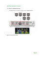
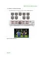
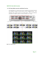
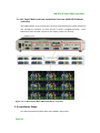
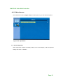
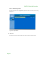
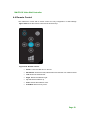
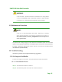
1
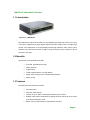
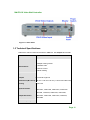
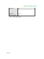
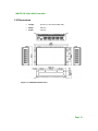
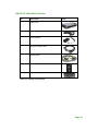
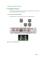
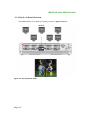
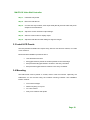
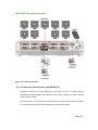
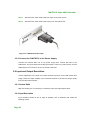
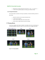
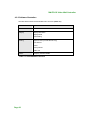
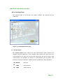
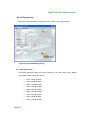
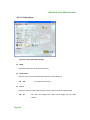
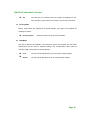
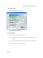
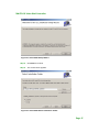
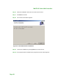
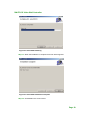
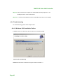
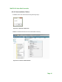
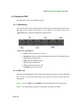
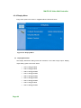
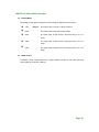
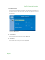
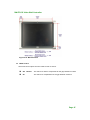
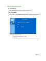
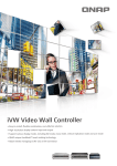
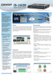
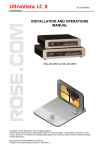
iVW-FD133 Video Wall Controller
MODEL:
iVW-FD133
Video Wall Controller
Supports 3 x 3 and 2 x 2 Video Wall Array
User Manual
Page i
Rev. 1.01
iVW-FD133 Video Wall Controller
Copyright
COPYRIGHT NOTICE
The information in this document is subject to change without prior notice in order to
improve reliability, design and function and does not represent a commitment on the part
of the manufacturer.
In no event will the manufacturer be liable for direct, indirect, special, incidental, or
consequential damages arising out of the use or inability to use the product or
documentation, even if advised of the possibility of such damages.
This document contains proprietary information protected by copyright. All rights are
reserved. No part of this manual may be reproduced by any mechanical, electronic, or
other means in any form without prior written permission of the manufacturer.
TRADEMARKS
All registered trademarks and product names mentioned herein are used for identification
purposes only and may be trademarks and/or registered trademarks of their respective
owners.
Page ii
iVW-FD133 Video Wall Controller
Table of Contents
COPYRIGHT ................................................................................................................... II
TABLE OF CONTENTS ................................................................................................ III
LIST OF FIGURES ..........................................................................................................V
LIST OF TABLES ......................................................................................................... VII
1 INTRODUCTION.......................................................................................................... 8
1.1 INTRODUCTION .......................................................................................................... 9
1.2 BENEFITS ................................................................................................................... 9
1.3 FEATURES .................................................................................................................. 9
1.4 EXTERNAL INTERFACES, SWITCHES AND LEDS ....................................................... 10
1.4.1 Front Panel ...................................................................................................... 10
1.4.2 Rear Panel ....................................................................................................... 10
1.5 TECHNICAL SPECIFICATIONS .....................................................................................11
1.6 DIMENSIONS ............................................................................................................ 13
2 UNPACKING LIST ..................................................................................................... 14
2.1 UNPACKING PRECAUTIONS ...................................................................................... 14
2.2 PACKING LIST .......................................................................................................... 14
3 INSTALLATION ......................................................................................................... 16
3.1 INSTALLATION OVERVIEW ....................................................................................... 17
3.1.1 Four (2 x 2) Panel Overview ........................................................................... 17
3.1.2 Six (2 x 3) Panel Overview............................................................................... 18
3.1.3 Six (3 x 2) Panel Overview............................................................................... 19
3.1.4 Nine (3 x 3) Panel Overview ............................................................................ 20
3.1.5 36 Panel, Multi-controller Installation Overview............................................ 21
3.1.6 81 Panel, Multi-controller Installation Overview (iVW-UD133 Master
controller) ................................................................................................................. 22
3.2 INSTALLATION STEPS ............................................................................................... 22
3.3 INSTALL LCD PANELS ............................................................................................. 23
3.4 MOUNTING .............................................................................................................. 23
Page iii
iVW-FD133 Video Wall Controller
3.5 CONNECT CABLES ................................................................................................... 24
3.5.1 Connect the Video Source and iVW-FD133 ..................................................... 25
3.5.2 Connect the iVW-FD133 to the Power Supply................................................. 26
3.6 INPUT AND OUTPUT RESOLUTION ............................................................................ 26
3.6.1 Screen Ratio ..................................................................................................... 26
3.6.2 Input Resolution ............................................................................................... 26
3.6.3 Output Resolution ............................................................................................ 27
3.7 DISPLAY MODE ........................................................................................................ 27
4 OSD FUNCTIONS ....................................................................................................... 28
4.1 MASK SETUP ........................................................................................................... 29
4.2 SMARTOSD ............................................................................................................. 29
4.2.1 Pre-installation Notice ..................................................................................... 29
4.2.2 Software Illustration ........................................................................................ 30
4.2.3 Install Software ................................................................................................ 36
4.2.4 Troubleshooting................................................................................................ 40
4.3 USING THE OSD ...................................................................................................... 42
4.3.1 OSD Buttons..................................................................................................... 42
4.3.2 OSD Lock ......................................................................................................... 42
4.3.3 Menu Structure ................................................................................................. 43
4.3.4 Display Menu ................................................................................................... 44
4.3.5 System Menu .................................................................................................... 48
4.4 REMOTE CONTROL .................................................................................................. 53
5 TROUBLESHOOTING AND MAINTENANCE ..................................................... 54
5.1 MAINTENANCE OVERVIEW ...................................................................................... 55
5.2 TROUBLESHOOTING ................................................................................................. 55
5.2.1 No Image on One Monitor ............................................................................... 55
5.2.2 No Image Two or Three Monitors .................................................................... 56
5.2.3 No Image on Any Monitor ................................................................................ 56
Page iv
iVW-FD133 Video Wall Controller
List of Figures
Figure 1-1: iVW-FD133 .............................................................................................................. 9
Figure 1-2: iVW-FD133 Front Panel ........................................................................................ 10
Figure 1-3: Rear Panel ............................................................................................................. 11
Figure 1-4: iVW-FD133 Dimensions ........................................................................................ 13
Figure 3-1: Four (2x2) Panel Setup ......................................................................................... 17
Figure 3-2: Six (2x3) Panel Setup ........................................................................................... 18
Figure 3-3: Six (3x2) Panel Setup ........................................................................................... 19
Figure 3-4: Nine Panel Setup .................................................................................................. 20
Figure 3-5: 36 Panel Setup ...................................................................................................... 21
Figure 3-6: 81 Panel Setup With iVW-UD133 Master Controller ............................................ 22
Figure 3-7: Mounting Brackets ............................................................................................... 24
Figure 3-8: Cable Connections ............................................................................................... 25
Figure 3-9: iVW-FD133 Video Input ......................................................................................... 26
Figure 3-10: Display Mode ...................................................................................................... 27
Figure 4-1: SmartOSD Interface Page..................................................................................... 31
Figure 4-2: SmartOSD Display Page ....................................................................................... 32
Figure 4-3: SmartOSD Setting Page ....................................................................................... 34
Figure 4-4: SmartOSD About Page ......................................................................................... 36
Figure 4-5: SmartOSD Setup Wizard ...................................................................................... 37
Figure 4-6: SmartOSD Select Installation Folder ................................................................... 37
Figure 4-7: SmartOSD Confirm Installation ............................................................................ 38
Figure 4-8: SmartOSD Installing ............................................................................................. 39
Figure 4-9: SmartOSD Installation Complete ......................................................................... 39
Figure 4-10: DLL Missing ........................................................................................................ 40
Figure 4-11: Windows Vista Error ........................................................................................... 41
Figure 4-12: Install as Administrator ...................................................................................... 41
Figure 4-13: OSD Buttons ....................................................................................................... 42
Figure 4-14: Display Menu ...................................................................................................... 44
Figure 4-15: Mask Control ....................................................................................................... 46
Figure 4-16: Mask Formula ..................................................................................................... 47
Page v
iVW-FD133 Video Wall Controller
Figure 4-17: Display Menu ...................................................................................................... 48
Figure 4-18: Information Screen ............................................................................................. 49
Figure 4-19: Input Select ......................................................................................................... 50
Figure 4-20: Input Select ......................................................................................................... 51
Figure 4-21: Input Select ......................................................................................................... 52
Figure 4-22: Remote Control ................................................................................................... 53
Page vi
iVW-FD133 Video Wall Controller
List of Tables
Table 1-1: Technical Specifications ........................................................................................ 12
Table 2-1: Package List Contents ........................................................................................... 15
Table 4-1: SmartOSD Menu Structure .................................................................................... 30
Table 4-2: OSD Menu Structure .............................................................................................. 43
Page vii
iVW-FD133 Video Wall Controller
Chapter
1
1 Introduction
Page 8
iVW-FD133 Video Wall Controller
1.1 Introduction
Figure 1-1: iVW-FD133
The iVW-FD133 video wall controller box is for displaying a single video input on an array
of monitors, implementing a large display without the inherent high costs of a single large
monitor. The iVW-FD133 is for large displays where high definition video output is also
essential. The video wall controller accepts a single DVI input, which is split over all the
monitors in the array.
1.2 Benefits
The benefits of the iVW-FD133 include:
Accurate, high-definition image
Silent operation
Simple setup
Cheap implementation of a large display
Major power savings over PC-based implementation
Space saving
1.3 Features
The features of the iVW-FD133 include:
DVI video input
Nine DVI video outputs
Support for up to 1920 x 1200 output resolution (per monitor)
Multiple video output combinations including full video wall mode, clone mode
and vertical replication mode
Bezel control compensates for gaps between monitors
Page 9
iVW-FD133 Video Wall Controller
1.4 External Interfaces, Switches and LEDs
This section provides an overview of the connectors, switches and indicators on the
iVW-FD133.
1.4.1 Front Panel
The front panel has the following buttons and indicators:
Power indicator LED
Video output LEDs
Video input LED
OSD menu keypad
Figure 1-2: iVW-FD133 Front Panel
1.4.2 Rear Panel
The rear panel has the following connectors, switches and indicators:
Page 10
9 x DVI outputs
1 x DVI video input
1 x Power input
1 x Power switch
1 x RS-232
iVW-FD133 Video Wall Controller
Figure 1-3: Rear Panel
1.5 Technical Specifications
iVW-FD133 video box features are listed in Table 1-1. See Chapter 2 for details.
Specification
Detail
Model Name
iVW-FD133
1. Multiple viewing modes
Main Features
2. Software OSD
3. Remote control
4. Bezel masking
Inputs
One DVI-D single link
Outputs
Nine DVI-D single link
Dimensions (W x D x H) 295 mm x 190 mm x 65 mm (71.4mm with rubber feet)
Cooling
Input Resolution
System fan
800x600, 1024x768, 1152x864, 1280x768, 1280x960,
1280x1024, 1600x1200, 1680x1050, 1920x1200
1024x768, 1360x768, 1280x1024, 1400x1500,
Output Resolution
1680x1050, 1600x1200, 1920x1200, 1366x768,
1920x1080
Power Adapter Input
90 VAC to 264 VAC
Page 11
iVW-FD133 Video Wall Controller
Specification
Detail
Power Adapter Output
40 W
Safety and Emission
CE, FCC, LVD
Temperature
0ºC – 40ºC
Power Consumption
35 W
Table 1-1: Technical Specifications
Page 12
iVW-FD133 Video Wall Controller
1.6 Dimensions
Height:
65 mm (71.4mm with rubber feet)
Width:
295 mm
Depth:
190 mm
Figure 1-4: iVW-FD133 Dimensions
Page 13
iVW-FD133 Video Wall Controller
Chapter
2
2 Unpacking List
2.1 Unpacking Precautions
When the iVW-FD133 is unpacked, please do the following:
Make sure the packing box is facing upwards so the iVW-FD133 does not fall
out of the box.
Make sure all the components shown in Section 2.2 are present.
2.2 Packing List
NOTE:
If some of the components listed in the checklist below are missing,
please do not proceed with the installation. Contact the reseller or
vendor that sold the iVW-FD133 from or contact a sales representative
directly. To contact a sales representative, please send an email to
[email protected].
The iVW-FD133 is shipped with the following components:
Page 14
iVW-FD133 Video Wall Controller
No.
Description
1
iVW-FD133
1
Power cord (European illustrated here)
1
Power adapter
1
Single-link DVI-D cable
1
RS-232 cable
1
Remote control
1
Mounting brackets & screws
Image
Table 2-1: Package List Contents
Page 15
iVW-FD133 Video Wall Controller
Chapter
3
3 Installation
Page 16
iVW-FD133 Video Wall Controller
3.1 Installation Overview
The iVW-FD133 supports 4-panel, 6-panel, 9-panel, 36-panel (requires five video boxes)
and 81-panel setups (requires ten video boxes).
3.1.1 Four (2 x 2) Panel Overview
The implementation of a 4-panel (2 x 2) array is shown in Figure 3-4 below.
Figure 3-1: Four (2x2) Panel Setup
Page 17
iVW-FD133 Video Wall Controller
3.1.2 Six (2 x 3) Panel Overview
The implementation of a 6-panel (2 x 3) array is shown in Figure 3-4 below.
Figure 3-2: Six (2x3) Panel Setup
Page 18
iVW-FD133 Video Wall Controller
3.1.3 Six (3 x 2) Panel Overview
The implementation of a 6-panel (3 x 2) array is shown in Figure 3-4 below.
Figure 3-3: Six (3x2) Panel Setup
Page 19
iVW-FD133 Video Wall Controller
3.1.4 Nine (3 x 3) Panel Overview
The implementation of a 9-panel (3 x 3) array is shown in Figure 3-4 below.
Figure 3-4: Nine Panel Setup
Page 20
iVW-FD133 Video Wall Controller
3.1.5 36 Panel, Multi-controller Installation Overview
The implementation of a 36-panel array using one iVW-FD133 as the master device and
nine iVW-FD122 controllers as slave devices is shown in Figure 3-5 below.
iVW-FD122 slave controller connects to four display panels.
Each
Refer to the iVW-FD122
User Manual for installation guides to connect the controller in a 2 x 2 array.
Figure 3-5: 36 Panel Setup
Page 21
iVW-FD133 Video Wall Controller
3.1.6 81 Panel, Multi-controller Installation Overview (iVW-UD133 Master
controller)
The implementation of an 81-panel array using one iVW-UD133 as the master device and
nine iVW-FD133 controllers as slave devices is shown in Figure 3-5 below.
iVW-FD133 slave controller connects to nine display panels in a 3x3 array.
Figure 3-6: 81 Panel Setup With iVW-UD133 Master Controller
3.2 Installation Steps
To install the iVW-FD133 please follow the installation steps below:
Page 22
Each
iVW-FD133 Video Wall Controller
Step 1: Install the LCD panels.
Step 2: Mount the iVW-FD133.
Step 3: Connect DVI output cables, video input cable (DVI-D), RS-232 cable and power
adapter to the iVW-FD133.
Step 4: Adjust the screen resolution output settings.
Step 5: Select a screen mode for display output.
Step 6: Adjust the iVW-FD133 mask settings to align the images.S
e
tp
0
:
3.3 Install LCD Panels
The LCD panels are installed as a square array, with two rows and two columns, for a total
of four monitors.
Recommended installation procedures are to
Use all identical monitors
Keep gaps between panels as small as possible for the best image
Keep all horizontal gaps between monitors in the array consistent
Keep all vertical gaps between monitors in the array consistent
3.4 Mounting
The iVW-FD133 must be placed on a table, desk or other firm surface. Optionally, the
iVW-FD133 can be mounted using the included mounting brackets. The installation
location must be:
Out of direct sunlight
Without anything on top of it
On a firm surface
Away from moisture and liquids
Page 23
iVW-FD133 Video Wall Controller
Figure 3-7: Mounting Brackets
3.5 Connect Cables
The cables that need to be attached are listed below and their connections are shown in
Figure 3-8:
DVI-D input cable – from the video source or computer to the iVW-FD133
DVI-D output cables – from the iVW-FD133 to the LCD panels or other slave
video box controllers. Make sure the cables are connected to the correct
monitors as shown in Figure 3-8.
Page 24
Power cable – from the power adapter
iVW-FD133 Video Wall Controller
Figure 3-8: Cable Connections
3.5.1 Connect the Video Source and iVW-FD133
Connect the video source to the iVW-FD133. If the video source is a computer with the
SmartOSD software installed, that computer can be used to adjust the monitor settings
without using the OSD.
The video source connects directly to the iVW-FD133 through a DVI-D single link cable.
To connect the video source to the iVW-FD133, follow the steps below.
Page 25
iVW-FD133 Video Wall Controller
Step 1: Attach the DVI video cable to the DVI output of the video source.
Step 2: Attach the DVI video cable to the DVI input on the iVW-FD133.Step 0:
Figure 3-9: iVW-FD133 Video Input
3.5.2 Connect the iVW-FD133 to the Power Supply
Connect the included PSU into an AC power supply then connect the PSU to the
iVW-FD133. The figure below shows the typical setup. There is no power switch, and the
iVW-FD133 turns on as soon as it is connected to the PSU.
3.6 Input and Output Resolution
Correct adjustment of the input and output resolutions gives a much better quality final
image. Follow the steps outlined in the subsections below to get the best image quality
from the video wall controller.
3.6.1 Screen Ratio
With auto-scaling it is not necessary to match the input and output aspect ratios.
3.6.2 Input Resolution
Input resolution should be set as high as possible. Pick a resolution that meets the
following criteria:
Page 26
iVW-FD133 Video Wall Controller
Matches the LCD panel aspect ratio (as shown in 錯誤! 找不到參照來源。)
Is the maximum possible (without exceeding input resolution limits)
3.6.3 Output Resolution
The output resolution should be set as high as possible, and meet the following criteria for
best results:
Matches video input and LCD panel resolution ratios
Is the maximum possible
Has a minimum width greater than half input width
Has a minimum height greater than half input height
3.7 Display Mode
There are five display mode options available. The display mode can be set through the
SmartOSD (4.2.2.2) or OSD menu (4.3.1). The modes are shown in Figure 3-10 below.
Figure 3-10: Display Mode
Page 27
iVW-FD133 Video Wall Controller
Chapter
4
4 OSD Functions
Page 28
iVW-FD133 Video Wall Controller
4.1 Mask Setup
The
GeniMask
masking
control
allows images to be adjusted slightly
larger than the visible screen size, to
compensate for the gaps between
panels. GeniMask simplifies this
process, allowing the masking to be adjusted simultaneously from a single controller. For
a setup with one controller and four panels the horizontal and vertical gaps are easily
adjusted according to the installation. With a master controller and four slave controllers,
the mask setup remains just a simple. While adjusting the master controller, all the slave
controllers are automatically adjusted, making setup time up to five times faster then
individually setting up each video controller.
Use either the SmartOSD (4.2.2.2) or OSD menu (4.3.4.1) to set the mask value.
4.2 SmartOSD
SmartOSD is a proprietary On-Screen-Display (OSD) software solution that enables easy,
remote monitor setting adjustments in a Windows environment. SmartOSD delivers
excellent performance and provides more flexibility than the typical OSD hardware
solutions when adjusting a monitor. SmartOSD also allows the screen output screen
resolution and mask size to be adjusted using the DVI connection.
4.2.1 Pre-installation Notice
Before installing SmartOSD software, please make sure one of the following operating
systems is installed:
Windows 2000
Windows XP
Windows Vista
Windows 7
Page 29
iVW-FD133 Video Wall Controller
4.2.2 Software Illustration
The table below shows the SmartOSD menu structure (Table 4-1).
Menu
Options
Interface
Interface Selection
Display
Display Resolution
Display Mode
Mask Setting
Setting
Digital I/O Test (for iVW-FD122 only)
Input Source
Power
Factory Reset
OSD Lock
About
Company Contact Details
Table 4-1: SmartOSD Menu Structure
Page 30
iVW-FD133 Video Wall Controller
4.2.2.1 Interface Page
The interface page is for choosing the interface between the computer and the
iVW-FD133.
Figure 4-1: SmartOSD Interface Page
Interface Select
The Interface Select option selects the data communication method between the
computer and the iVW-FD133. If the computer also provides the video input, then
communication can be done over the DVI cable. Serial ports can also be used for data
communication. The dropdown list shows all communications ports by default. The
following are shown for reference, as the exact ports available are system dependent.
DDC2Bi
DVI input
COM1
First serial port
COM3
Third serial port
Page 31
iVW-FD133 Video Wall Controller
4.2.2.2 Display Page
The Display Page adjusts the configuration of the panels in the video wall array.
Figure 4-2: SmartOSD Display Page
Display Resolution
The Display Resolution setting shows the resolution of the video image output. Display
output setting options are shown below.
Page 32
1024 x 768 @ 60 MHz
1360 x 768 @ 60 MHz
1280 x 1024 @ 60 MHz
1400 x 1050 @ 60 MHz
1680 x 1050 @ 60 MHz
1600 x 1200 @ 60 MHz
1920 x 1200 @ 60 MHz
1366 x 768 @ 60 MHz
1920 x 1080 @ 60 MHz
iVW-FD133 Video Wall Controller
Display Mode
The display mode option configures how the image is displayed on the screen.
1x1
DEFAULT
The video input is cloned on all the monitors
2x2
The video input is tiled over all the panels.
2x3
The video input is split across a six-panel array in a 2 x 3
setup
3x2
The video input is split across a six-panel array in a 3 x 2
setup
3x3
The video input is split across a nine-panel array in a 3 x 3
setup
Mask Mode
Mask mode toggles the masking function.
Off
The video box doesn’t compensate for gaps between LCD panels
On DEFAULT
The video box compensates for the gaps between LCD panels
H Mask %
The horizontal mask compensates for the horizontal gap between panels. Enter the bezel
width (mm) and viewable width (mm) into the corresponding data box to calculate the
correct figure.
V Mask %
The vertical mask compensates for the vertical gap between panels. Enter the bezel
height (mm) and viewable height (mm) into the corresponding data box to calculate the
correct figure.
Page 33
iVW-FD133 Video Wall Controller
4.2.2.3 Setting Page
Figure 4-3: SmartOSD Setting Page
GPIO
The GPIO settings are for the iVW-FD122 only.
Input Source
The input video source is automatically selected by the iVW-FD133.
DVI
Input video source is DVI
Power
The power option turns the iVW-FD133 on and off. Select one of the options below.
On
The video box displays the video source image onto the video
outputs.
Page 34
iVW-FD133 Video Wall Controller
Off
The video box is in standby mode. No images are displayed on the
video outputs, but the video box is ready to receive data commands.
Factory Mode
Factory mode resets the iVW-FD133 to default settings. Two options are available for
resetting the values.
Factory Default
Resets the video box to the factory defaults.
OSD Mode
Two sets of options are available. The lock/unlock option sets whether the front panel
OSD buttons can be used for adjusting settings. The normal/rotation option sets the
onscreen OSD to a horizontal or vertical position.
Lock
The front panel OSD buttons cannot be used to adjust settings
Unlock
The front panel OSD buttons can be used to adjust settings
Page 35
iVW-FD133 Video Wall Controller
4.2.2.4 About Page
The About Page displays contact information.
Figure 4-4: SmartOSD About Page
4.2.3 Install Software
To install the software, please follow the steps below:
Step 1: Follow the instructions from the interactive installer to install the SmartOSD on
the system.
Step 2: Insert the installation disk that came with the system and open the installation
file.
Step 3: The welcome screen shown below appears.
Page 36
iVW-FD133 Video Wall Controller
Figure 4-5: SmartOSD Setup Wizard
Step 4: Click Next to continue.
Step 5: The screen below appears.
Figure 4-6: SmartOSD Select Installation Folder
Page 37
iVW-FD133 Video Wall Controller
Step 6: Select the installation folder from the screen shown above.
Step 7: Click Next to continue.
Step 8: The screen shown below appears.
Figure 4-7: SmartOSD Confirm Installation
Step 9: Confirm the installation by clicking Next in the screen above.
Step 10: The program starts to install and the progress bar shown below appears.
Page 38
iVW-FD133 Video Wall Controller
Figure 4-8: SmartOSD Installing
Step 11: When the installation is complete the screen below appears.
Figure 4-9: SmartOSD Installation Complete
Step 12: Click Close in the screen above.
Page 39
iVW-FD133 Video Wall Controller
Step 13: After quick setup is complete, the SmartOSD wizard logo appears on the
desktop as shown in the screen below.
Step 14: To access the SmartOSD, click the SmartOSD wizard logo on the desktop.
S
e
tp
0
:
4.2.4 Troubleshooting
For troubleshooting, please see the steps below:
4.2.4.1 Windows 2000 Installation Failure
Installation fails under Windows 2000 and shows the following image:
Figure 4-10: DLL Missing
Solution: Download and install service pack Windows Installer 3.1
Page 40
iVW-FD133 Video Wall Controller
4.2.4.2 Vista Installation Failure
Installation fails under Vista while showing following image:
Figure 4-11: Windows Vista Error
Solution: Install SmartOSD.exe as the administrator authority
Figure 4-12: Install as Administrator
Page 41
iVW-FD133 Video Wall Controller
4.3 Using the OSD
The OSD menu functions are described below.
4.3.1 OSD Buttons
There are several on-screen-display (OSD) control buttons oriented either vertically on the
right side of the monitor front panel or on the bottom of the monitor front panel.
482H482H
Figure 4-13 shows a typical arrangement of OSD controls.
Figure 4-13: OSD Buttons
Power. Turns the video box on and off.
Menu/Enter. Enters the OSD, selects items and sets the new values entered.
Left. Moves the selection left.
Right. Moves the selection right.
Up. Moves the selection up.
Down. Moves the selection down.
Auto/Exit. Exits from any menu.
4.3.2 OSD Lock
The OSD front panel buttons can be locked using the OSD lock function. To turn the OSD
lock on and off, follow the steps below. (The OSD can also be locked using the
SmartOSD).
Step 1: Push the “Right” and “Auto/Exit” buttons simultaneously for a few seconds.
Step 2: The OSD display shows the current status as locked or unlocked. S
e
tp
0
:
Page 42
iVW-FD133 Video Wall Controller
4.3.3 Menu Structure
The table below shows the OSD menu structure.
Menu
Options / Submenu
Display
Output
Options
Display Mode
Mask ->
Horizontal Mask
Vertical Mask
Mask On/Off
Setting
Factory
Information
Input ->
DVI
Component
Miscellaneous ->
OSD ->
OSD Timer
OSD Rotation
Identify
Table 4-2: OSD Menu Structure
Page 43
iVW-FD133 Video Wall Controller
4.3.4 Display Menu
Image menu options are shown in Figure 4-14 and described below.
484H484H
Figure 4-14: Display Menu
Display Resolution
The Display Resolution setting shows the resolution of the video image output. Display
output setting options are shown below.
Page 44
1024 x 768 @ 60 MHz
1360 x 768 @ 60 MHz
1280 x 1024 @ 60 MHz
1400 x 1050 @ 60 MHz
1680 x 1050 @ 60 MHz
1600 x 1200 @ 60 MHz
1920 x 1200 @ 60 MHz
1366 x 768 @ 60 MHz
1920 x 1080 @ 60 MHz
iVW-FD133 Video Wall Controller
Display Mode
The display mode option configures how the image is displayed on the screen.
1x1
DEFAULT
The video input is cloned on all the monitors
2x2
The video input is tiled over all the panels.
2x3
The video input is split across a six-panel array in a 2 x 3
setup
3x2
The video input is split across a six-panel array in a 3 x 2
setup
3x3
The video input is split across a nine-panel array in a 3 x 3
setup
Mask Control
The Mask control compensates for the gaps between monitors in the video wall array.
These settings are shown in 4.3.4.1.
Page 45
iVW-FD133 Video Wall Controller
4.3.4.1 Mask Control
The mask control menu adjusts the mask settings. The mask settings compensate for the
gaps between monitors in the video wall array. The mask control options are shown and
described below.
Figure 4-15: Mask Control
Horizontal Mask
Set the horizontal mask according to the formula in Figure 4-16.
Vertical Mask
Set the vertical mask according to the formula in Figure 4-16.
Page 46
iVW-FD133 Video Wall Controller
Figure 4-16: Mask Formula
Mask Control
The mask control option turns the mask control on and off.
Off DEFAULT
The video box doesn’t compensate for the gap between monitors
On
The video box compensates for the gap between monitors
Page 47
iVW-FD133 Video Wall Controller
4.3.5 System Menu
System menu options are shown in Figure 4-17 and described in the subsections below.
485H485H
Figure 4-17: Display Menu
Factory Reset
Factory reset returns all the settings to the factory default settings.
Information
Shows video box version information. The information details are shown in 4.3.5.1.
Input Select
Input select allows selection of the input source. Input selection is shown in 4.3.5.2.
Misc
Misc allows other OSD features to be adjusted. Misc options are shown in 4.3.5.3.
Page 48
iVW-FD133 Video Wall Controller
Identify Monitors
Identify monitors displays the monitor’s ID within the monitor array.
4.3.5.1 Information
The information screen in Figure 4-18 shows some basic information about the video box
and the monitor. The details are described below.
Figure 4-18: Information Screen
Model name, firmware version and date
Input type
Video box ID (identifies the current video box in a larger array of video boxes)
Page 49
iVW-FD133 Video Wall Controller
4.3.5.2 Input Select
The input select screen in Figure 4-19 shows the input options.
Figure 4-19: Input Select
The video box automatically selects the correct input source setting. The following options
are available.
Page 50
DVI
iVW-FD133 Video Wall Controller
4.3.5.3 Miscellaneous
The miscellaneous menu (Figure 4-20) allows the option to go to the OSD setup menu.
Figure 4-20: Input Select
OSD Configuration
OSD configuration adjusts the display settings for the OSD display. OSD configuration
settings are shown in 4.3.5.3.1.
Page 51
iVW-FD133 Video Wall Controller
4.3.5.3.1 OSD Configuration
The OSD configuration menu (Figure 4-21) adjusts the rotation of the OSD, and how long
it displays for.
Figure 4-21: Input Select
OSD Timer
The OSD Timer sets how long the OSD screen stays on after the last button press.
Page 52
iVW-FD133 Video Wall Controller
4.4 Remote Control
The iVW-FD133 comes with a remote control for easy configuration of OSD settings.
491H491H
Figure 4-22 shows the remote control and its function keys.
Figure 4-22: Remote Control
Power. Turns the video box on and off.
Menu/Enter. Enters the OSD, selects items and sets the new values entered.
Left. Moves the selection left.
Right. Moves the selection right.
Up. Moves the selection up.
Down. Moves the selection down.
Auto/Exit. Exits from any menu.
Page 53
iVW-FD133 Video Wall Controller
Chapter
5
5 Troubleshooting and
Maintenance
Page 54
iVW-FD133 Video Wall Controller
WARNING:
Take Anti-Static precautions whenever maintenance is being carried
out on the embedded system components. Failure to take anti-static
precautions can cause permanent embedded system damage.
5.1 Maintenance Overview
NOTE:
There are no user-serviceable parts inside. Make sure to carefully
follow all the instructions in this section to diagnose any problems. If
the problem persists, email [email protected] for help from a
sales representative
To preserve the working integrity of the iVW-FD133 embedded system, the embedded
system must be properly maintained. If embedded system components need replacement,
the proper maintenance procedures must be followed to ensure the embedded system
can continue to operate normally.
5.2 Troubleshooting
This section provides some simple troubleshooting suggestions.
5.2.1 No Image on One Monitor
If there is no image on one monitor, follow these steps to remedy the problem.
5.2.1.1 Check Monitor Power
Step 1: Check that the monitor is turned on.
Step 2: Check that the power source for the monitor is turned on.
Page 55
iVW-FD133 Video Wall Controller
Step 3: Check that the power source has the correct power rating (check panel
specifications for details).
Step 4: Make sure the LCD panel power cables are securely fastened to the monitor and
to the power source.S
e
tp
0
:
5.2.1.2 Check Panel Video Connection
Check to see that the video cable is fitted correctly.
Step 1: Check that the monitor is connected to the iVW-FD133.
Step 2: Securely attach the video cable to the panel and to the iVW-FD133.
Step 3: Fasten the video cable at both ends and tighten the video cable screws.S
e
tp
0
:
5.2.2 No Image Two or Three Monitors
If there is no image on more than one of the panels, then repeat the steps in Section 5.2.1
for all of the monitors in the array.
5.2.3 No Image on Any Monitor
If no image displays on any monitors, repeat the steps in Section 5.2.1 for all the monitors
in the array, then try the following additional steps.
5.2.3.1 Check Video Box Power
Make sure that the video box is powered on.
Step 1: Check the power supply is connected to the power source.
Step 2: Check that the iVW-FD133 is connected to the power supply.S
e
tp
0
:
5.2.3.2 Check Source Video Connection
Check to that the source video cable is securely connected to the iVW-FD133.
Step 1: Securely attach the video cable from the video source to the iVW-FD133.
Page 56
iVW-FD133 Video Wall Controller
Step 2: Fasten the video cable at both ends and tighten the video cable screws. Step 0:
Page 57