1
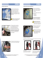
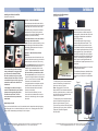
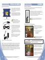
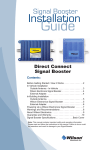
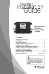
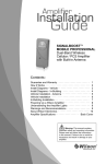
SIGNALBOOST™
Dual-Band Mobile
Signal Booster
(811510 is single band)
Contents:
How it Works . . . . . . . . . . . . . . . . . . . . . . . . . . . . . . . . . . . . . 1
Before Getting Started . . . . . . . . . . . . . . . . . . . . . . . . . . . . . . 2
Installation Overview . . . . . . . . . . . . . . . . . . . . . . . . . . . . . . . 2
In-Vehicle Installation. . . . . . . . . . . . . . . . . . . . . . . . . . . . . . . 3
Outside Antenna . . . . . . . . . . . . . . . . . . . . . . . . . . . . . . . . 3
Signal Booster . . . . . . . . . . . . . . . . . . . . . . . . . . . . . . . . . 4
Cellular Cradle Plus . . . . . . . . . . . . . . . . . . . . . . . . . . . . . 5
Ultra Slim Antenna . . . . . . . . . . . . . . . . . . . . . . . . . . . . . . 6
Powering Up the Signal Booster . . . . . . . . . . . . . . . . . . . . . . 7
In-Building Installation . . . . . . . . . . . . . . . . . . . . . . . . . . . . . . 8
Warnings and Recommendations . . . . . . . . . . . . . . . . . . . . . 9
Guarantee and Warranty . . . . . . . . . . . . . . . . . . . . . . . . . . . 10
Signal Booster Specifications . . . . . . . . . . . . . . . . Back Cover
Appearance of device and accessories may vary.
Note: This manual contains important safety and operating information.
Please read and follow the instructions in this manual. Failure to do so
could be hazardous and result in damage to your Signal Booster.
Installation Instructions for the Following Wilson Electronics Signal Booster:
SIGNALBOOST™ Dual-Band Mobile Signal Booster
Model #811210
FCC ID: PWO819DA
IC: 4726A-819DA
The term “IC” before the radio certification number only signifies that
Industry Canada technical specifications were met.
Not For Sale in U.S. / Canada: 811510, 811514, 811710, 811714, 811910, 811914
Inside this Package
Items below may be included with some kits
(Products may change due to upgrades)
DUAL-BAND
Signal Booster
12 V DC power supply
(vehicle)
Cellular
Cradle Plus
Adhesive/Screw
Swivel Bracket
Ultra Slim
Antenna
Optional Items and Accessories
Cradle Arms
12" MagnetMount Antenna
4" Mini MagnetMount Antenna
AC/DC power supply
(859903)
12-inch Magnet-Mount
Antenna
(301103)
Soft Carrying
Case
(859924)
The following steps provide a summary of the Signal Booster/antenna installation
process using the Mini Magnet-Mount or Magnet Mount Antenna. However, they are not
a substitute for the complete installation instructions on the following pages, which you
should read thoroughly. If you are using a different Outside Antenna, follow the specific
instructions that come with it.
STEP 1: Install the Outside Antenna
STEP 2: Install the Signal Booster
STEP 3: Attach the Cellular Cradle Plus or Ultra Slim Antenna
Attach the Cellular Cradle Plus or Ultra Slim cable to the connector labeled “Inside
Antenna” on the Signal Booster. If using the Ultra Slim Antenna, attach the antenna to your
cell phone or cellular data card with the VELCRO® provided. (See page 6)
STEP 4: Power up the Signal Booster
Window Bracket
(901128)
Ultra Slim Antenna
(301143)
Available at www.WilsonElectronics.com
Appearance of device and accessories may vary.
How it Works
The Signal Booster, in conjunction with the use of an Outside Antenna, will collect the
signal from the cell tower and send it through the cable to the Signal Booster. The state-ofthe-art technology that powers this Signal Booster is designed to increase your signal more
than 20 times, and reduce disconnects and dropped calls. The boosted signal is then sent
to the Cellular Cradle Plus or Ultra Slim Antenna (depending on which one you have). Your
cellular device receives the improved signal. When the cellular device transmits, the signal
goes through the Cellular Cradle Plus or Ultra Slim Antenna, boosted by the Signal Booster
and broadcasted back to the cell tower through the Outside Antenna.
If your kit contains the Cellular Cradle Plus, it provides a convenient place to stow your cell
phone and allows the driver to keep both hands on the wheel while using the phone, greatly
increasing safety. This kit may include different mounting options for installing the cradle on
the dash or console of your vehicle.
1
Installation Overview
Position the Signal Booster in a well-ventilated location away from direct sunlight. Run the
cable from the Outside Antenna and attach it to the connector labeled “Outside Antenna” on
the Signal Booster. (See page 4)
Cellular
Cradle Plus
(301246)
Mini Magnet-Mount
Antenna
(301113)
This guide will help you properly install your Wilson Electronics SIGNALBOOST™
Dual-Band Signal Booster. It is important to read through all of the installation steps
for your particular application prior to installing any equipment. Read through the
instructions, visualize where all the equipment will need to be installed and do a soft
installation before mounting any equipment. Please contact Wilson Electronics Technical
Support with any questions at 866-294-1660. You may also send an email to
[email protected]
For a In-Vehicle installation, attach the Outside Antenna in the center of the vehicle’s roof
and run the cable through the door to the Signal Booster. For In-Building installation, affix
the optional window bracket to a window with the suction cups, attach the Outside Antenna
to the bracket and run the cable to the Signal Booster. (See page 3 for In-Vehicle, and page
8 for In-Building.)
(Products may change due to upgrades)
Adhesive
Bracket
Before Getting Started
IMPORTANT! Before connecting the power supply, ensure that both the Outside Antenna
cable and the Cradle Plus or Ultra Slim cable are connected. (See page 7)
Magnet-Mount
Antenna
Laptop
Connection
Cell Phone
Connection
SIGNALBOOST™
Power Supply
SIGNALBOOST™
Cellular
Cradle Plus
Signal Booster
AC Power Supply and
Window Bracket
sold separately
(Part #859940)
In-Vehicle Installation Diagram
In-Building Installation Diagram
If your kit does not contain a Cellular Cradle Plus, it is available for purchase at
www.WilsonElectronics.com
Contact Wilson Electronics Technical Support Team with any questions at 866-294-1660
Or email: [email protected] Hours: 7am to 6pm MST.
Contact Wilson Electronics Technical Support Team with any questions at 866-294-1660
Or email: [email protected] Hours: 7am to 6pm MST.
2
In-Vehicle
Installing the Outside Antenna
In-Vehicle
Installing the Wilson Electronics Signal Booster
Select a location to install the Signal
Booster that is away from excessive heat,
direct sunlight or moisture and that has
proper ventilation.
To receive the best cell signal, select a
location in the center of the vehicle’s roof
that is 12 inches away from any other
antennas and free of obstructions. The
antenna must be installed vertically. Signal
performance will be degraded if the antenna
is not vertical.
!
Carefully
Pull Down
Door Seal
Run Cable
Under
Seal
Recommended installation locations for the
Signal Booster are:
• Under the seat
• Under the dash
Run the cable from the Outside Antenna
and attach it to the connector labeled
“Outside Antenna” on the Signal Booster.
Warning: The antenna used with this Signal
Booster must have a separation distance of
at least 12 inches from all persons.
!
The antenna cable may run through the
door to the Signal Booster. For a more
professional looking installation, run
the antenna cable under the door seal.
Carefully pull down the door seal. Run the
cable through the seal and push the seal
back into place. This prevents constant
wear and tear on the cable as the door
opens and closes.
Warning: Do not plug in the DC power
supply until the Outside Antenna and
Cellular Cradle Plus or Ultra Slim Antenna
cables are attached to the Signal Booster.
Attach the cable from the Cellular Cradle
Plus or the Ultra Slim Antenna to the
connector on the Signal Booster.
!
Warning: Do not plug the Signal Booster
directly into the cell phone or cellular data
card using an antenna adapter. It could
damage the Signal Booster, cell phone
and/or cellular data card.
Adjusting the Cradle Plus Arms
Included with your Cradle Plus are various sized arms, which will provide you with multiple
options to customize the Cradle to fit your phone.
The antenna cable is small enough to easily
tuck under the door seal or plastic molding.
Tuck Cable
Under Seal
3
Contact Wilson Electronics Technical Support Team with any questions at 866-294-1660
Or email: [email protected] Hours: 7am to 6pm MST.
1. Change arms
2. Reposition arms
Gently grab the arm and lift upward until
the arm slides free from the Cradle.
Position the arm above a different slot on
the Cradle. Gently slide the arm down until
the arm is firmly in place.
Contact Wilson Electronics Technical Support Team with any questions at 866-294-1660
Or email: [email protected] Hours: 7am to 6pm MST.
4
In-Vehicle
In-Vehicle
Installing the Ultra Slim Antenna
(Included in some kits)
Installing the Cellular Cradle Plus
(Included in some kits)
Option 1 - Adhesive Bracket
Clean the area where the bracket will be
mounted with the alcohol wipe (included in
some kits) and a soft cloth. Allow to dry.
The Ultra Slim must be placed directly
on the cell phone or cellular data card to
work properly. Attach the Ultra Slim to the
cell phone or cellular data card with the
VELCRO® provided.
Peel the backing to expose the adhesive
and press the bracket onto the desired
location in the vehicle. Note: Be sure the
bracket is positioned vertically.
Allow the adhesive to cure for 24 hours
before you attach the cradle.
The Ultra Slim cable is long enough to
reach the Signal Booster location. This
allows for ease and convenience of use.
Note: Once the cradle is attached, you can
adjust the angle of the adhesive bracket
by applying gentle pressure to the top or
bottom of the cradle.
To adjust the Ultra Slim for the best signal,
go to a weak signal location where your cell
phone registers only 1-2 bars without the
Ultra Slim connected. (Be sure the Signal
Booster is turned off when checking for low
signal). Then, attach the Ultra Slim to the
phone, power up the Signal Booster and
you should see a signal improvement of 2 or
more bars.
Option 2 - Adhesive/Screw Swivel
Bracket
Clean the area where the bracket is to be
mounted with the alcohol wipe (included in
some kits) and a soft cloth. Allow to dry.
For best mounting results and longterm performance, we suggest that
you choose a flat smooth surface
like the console area of your vehicle
between the two front seats. If this is
not available in your vehicle, you may
mount the cradle on the front of the
dashboard.
If mounting the cradle on a sloped
area of the dashboard in your vehicle,
please note that gravity may affect
the adhesive over time. Use the
screw mount for a more permanent
attachment.
For an adhesive mount, peel the backing
to expose the adhesive and press the
bracket onto the desired location in the
vehicle. Allow the adhesive to cure for
24 hours before you attach the cradle.
For a screw mount, use an ice pick or awl
to punch through the adhesive and expose
the four screw holes in the bracket. Note:
Screws are not included in this kit.
Using the bracket as a template, mark the
locations for the screws as shown, drill
pilot holes and attach the bracket with
screws (not included).
Once the cradle is attached, you can
loosen the knurled wheel and swivel the
hook to the desired angle, then re-tighten
the wheel.
Attaching the Cradle
Once you have installed the mount in the desired location, attach the cradle by aligning
the rectangular hole on its back with the hook on the mount. Grasping the sides of the
cradle, slide it downward approximately ¼ inch into place.
Note: Many phones take up to 30 seconds
to reset the bar indicator.
Cellular data card
For cell phones with an internal antenna,
place the Ultra Slim on the back of the
phone near the top. (Figure 1)
To maximize performance, attach the Ultra
Slim as close as possible to the original
antenna on your cell phone or cellular data
card.
Figure 1
Figure 2
Note: Certain phones, such as the
Motorola RAZR, have internal antennas at
the base, rather than the top, in which case
the Ultra Slim should be attached at the
bottom rear of the phone.
For cell phones with an external antenna,
place the Ultra Slim directly below the
phone’s original antenna. (Figure 2)
If you have any questions as to the location
of the antenna on your phone, call Wilson
Electronics Technical Support at:
866-294-1660.
To Signal Booster
5
Contact Wilson Electronics Technical Support Team with any questions at 866-294-1660
Or email: [email protected] Hours: 7am to 6pm MST.
Contact Wilson Electronics Technical Support Team with any questions at 866-294-1660
Or email: [email protected] Hours: 7am to 6pm MST.
6
In-Vehicle & In-Building
In-Building
Installing the Outside Antenna
Powering Up the Signal Booster
Make sure both the Outside Antenna and
Cellular Cradle Plus or Ultra Slim Antenna
cables are connected before powering up
the Signal Booster.
Connect the power cable from the power
supply to the Signal Booster input marked
“12 V DC” and insert the large end into the
power socket or the vehicle power outlet.
Carefully insert the power cable
!
Warning: Use only Wilson
Electronics power supply units. Use
of a non-Wilson Electronics product
may damage your equipment.
To receive the best cell signal, select a window location at least 12 inches away from any
radio or television antennas and free of obstructions.
Using the suction cups, position the mounting bracket on the
window at a height convenient to where the Signal Booster will
be located, then attach the antenna to the bracket.
The antenna must be installed vertically. Signal performance will
be degraded if the antenna is not vertical.
!
Warning: The antenna used with this Signal Booster must
have a separation distance of at least 12 inches from all
persons.
Installing the Wilson Electronics Signal Booster
The Signal Booster may remain on all the
time. However, leaving the Signal Booster
on in a vehicle when it is not running can
discharge the battery in a day or two.
(Power supply may change due to upgrades)
A good option is to power the Signal
Booster through the ignition switch so the
Signal Booster is turned on and off with the
vehicle.
IMPORTANT: Do not power up the Signal
Booster unless both antenna cables are
attached to the Signal Booster.
AC/DC power supply (sold separately) (859903)
Note: The aluminum casing of the Signal Booster will adjust very quickly to the ambient
temperature of its environment. For example, in the summer, when the inside of a car
can reach 140° Fahrenheit, the Signal Booster temperature may be 150° or higher. The
casing will be hot to the touch, similar to a metal door handle or steering wheel. Such
high temperatures will not damage the Signal Booster, nor do they pose a fire risk. As
recommended in these instructions, when installing the Signal Booster in a vehicle, select
a location with adequate ventilation, such as under the seat or dashboard. Keep the area
free of items that could block air flow to the Signal Booster.
Select a location to install the Signal
Booster that is away from excessive heat,
direct sunlight or moisture and that has
proper ventilation.
Recommended installation locations are:
• On a desk or table top
• In a bookshelf
• On the floor
!
Warning: Do not plug in the AC power
supply until both antenna cables are
attached to the Signal Booster.
Wilson® Electronics recommends that all AC power
supplies for home electronics be plugged into a
Surge Protector Power Strip.
Run the cable from the Outside Antenna
and attach it to the connector labeled
“Outside Antenna” on the Signal Booster.
Attach the Cellular Cradle Plus or Ultra
Slim cable to the connector labeled “Inside
Antenna” on the Signal Booster.
Then attach the Cellular Cradle Plus or
Ultra Slim to your cell phone or data card.
(See page 5 & 6.)
7
Contact Wilson Electronics Technical Support Team with any questions at 866-294-1660
Or email: [email protected] Hours: 7am to 6pm MST.
Contact Wilson Electronics Technical Support Team with any questions at 866-294-1660
Or email: [email protected] Hours: 7am to 6pm MST.
8
Warnings and Recommendations
Warning:
The antenna must be installed with a separation distance of at
least 12 inches from any vehicle occupant and must not be located
or operating in conjunction with any other antenna or Signal
Booster. Use of this Signal Booster with an antenna providing
gain higher than 6.12 dBi is in violation of FCC regulations for
which the offender is fully liable. All Wilson Electronics mobile
antennas provide 6.12 dBi gain or less.
Warning:
Do not connect the power supply to the Signal Booster until
the Outside Antenna and Cellular Cradle Plus (or Ultra Slim
Antenna) cables are attached to the Signal Booster.
Warning:
Do not plug the Signal Booster directly into the cell phone or
cellular data card using an antenna adapter. It could damage
the Signal Booster, cell phone and/or cellular data card.
30-Day Money-Back Guarantee
All Wilson Electronics products are protected by Wilson Electronics 30-day moneyback guarantee. If for any reason the performance of any product is not acceptable,
simply return the product directly to the reseller with a dated proof of purchase.
1-Year Warranty
Wilson Electronics Signal Boosters are warranted for one (1) year against defects
in workmanship and/or materials. Warranty cases may be resolved by returning the
product directly to the reseller with a dated proof of purchase.
Signal Boosters may also be returned directly to the manufacturer at the consumer’s
expense, with a dated proof of purchase and a Returned Material Authorization (RMA)
number supplied by Wilson Electronics. Wilson Electronics shall, at its option, either
repair or replace the product. Wilson Electronics will pay for delivery of the repaired
or replaced product back to the original consumer if located in the USA.
This warranty does not apply to any Signal Boosters determined by Wilson Electronics
to have been subjected to misuse, abuse, neglect, or mishandling that alters or
damages physical or electronic properties.
RMA numbers may be obtained by phoning Technical Support at 866-294-1660.
About Wilson Electronics
Wilson Electronics, Inc. has been a leader
in the wireless communications industry for
over 40 years. The company designs and
manufactures Signal Boosters, antennas and
related components that significantly improve
cellular signal reception and transmission in
a wide variety of applications, both mobile
(marine, RV, vehicles) and in-building (home,
office, M2M).
With extensive experience in antenna and Signal Booster research and design,
the company’s engineering team uses a state-of-the-art testing laboratory,
including an anechoic chamber and network analyzers, to fine-tune antenna
designs and performance. For its Signal Boosters, Wilson Electronics uses
a double electrically insulated RF enclosure and cell tower simulators for
compliance testing.
All products are engineered and assembled in the company’s 55,000-square-foot
headquarters in St. George, Utah. Wilson Electronics has product dealers in all
50 states as well as in countries around the world.
This device complies with Part 15 of FCC rules. The transaction is subject to two
conditions: (1) This device may not cause harmful interference, and (2) this device
must accept any interference received, including interference that may cause undesired
operation. Changes or modifications not expressly approved by Wilson Electronics could
void the authority to operate this equipment.
Disclaimer: The information provided by Wilson Electronics, Inc. is believed to
be complete and accurate. However, no responsibility is assumed by Wilson
Electronics, Inc. for any business or personal losses arising from its use, or for
any infringements of patents or other rights of third parties that may result from
its use.
Copyright © 2011 Wilson Electronics, Inc. All rights reserved.
One or more of the following U.S. Patent numbers may apply to the Signal Booster in this
product – D596,614; D596,615; D563,381;7,729,669; 7,486,929; 7,729,656; 7,409,186;
7,783,318; 7,684,838; 12,714,994.
3301 East Deseret Drive, St. George, UT 84790
For additional Technical Support visit www.WilsonElectronics.com
or email at: [email protected]
Phone: 866-294-1660 Local: 435-673-5021 Fax: 435-656-2432
www.twitter.com/WilsonCellular
www.facebook.com/WilsonCellular
9
Contact Wilson Electronics Technical Support Team with any questions at 866-294-1660
Or email: [email protected] Hours: 7am to 6pm MST.
Contact Wilson Electronics Technical Support Team with any questions at 866-294-1660
Or email: [email protected] Hours: 7am to 6pm MST.
10
Signal Booster Specifications
Model Number
Connectors
Impedance (input/output)
Dimensions
Weight
Frequency
1
Passband Gain (nominal)
800 MHz (uplink/downlink)
1900 MHz (uplink/downlink)
2
20 dB Bandwidth (nominal)
800 MHz (uplink/downlink)
1900 MHz (uplink/downlink)
³Power output for single cell phone (uplink)
CDMA
GSM
EDGE
AMPS
Power output for single received channel
(downlink)
Power output for multiple
received channels (downlink).
The maximum power is reduced by
the number of channels:
CDMA
GSM
EDGE
AMPS
Dual-Band Specifications
811210
FME-Male
50 Ohms
5 x 3.5 x 1.2 inch or 12.7 x 8.9 x 3 cm
1.03 lbs or 0.468 kg
824-894 MHz / 1850-1990 MHz
25 dB / 25 dB
25 dB / 25 dB
53 MHz / 62 MHz
112 MHz / 110 MHz
800 MHz
+33.0 dBm
+34.3 dBm
+34.1 dBm
+30.1 dBm
1900 MHz
+29.3 dBm
+30.3 dBm
+30.2 dBm
800 MHz
1900 MHz
+5.1 dBm
+3.2 dBm
+3.2 dBm
+3.2 dBm
+6.8 dBm
+4.4 dBm
+4.6 dBm
4
Maximum Power
Number of
channels
2
3
4
5
6
Noise Figure (typical)
Isolation
Power Requirements
800 MHz
1900 MHz
+1.0 dBm
-2.5 dBm
-5.0 dBm
-7.0 dBm
-8.5 dBm
+1.7 dBm
-1.8 dBm
-4.3 dBm
-6.3 dBm
-7.8 dBm
3.5 dB nominal
uplink/downlink more than 50 dB
12 V, 2 A (subject to uplink power)
Notes:
1. Nominal gain is the maximum gain at any frequency in the passband.
2. Nominal bandwidth is the difference between two frequencies that are adjacent to the passband where the amplification is 20 dB
lower than the passband amplification. One of the frequencies is lower than the passband and the other is higher.
3.The Manufacturer’s rated output power of this equipment is for single carrier operation. For situations when multiple carrier
signals are present, the rating would have to be reduced by 3.5 dB, especially where the output signal is re-radiated and can
cause interference to adjacent band users. This power reduction is to be by means of input power or gain reduction and not by
an attenuator at the output of the device.
4. The maximum power for 2 or more simultaneous signals will be reduced by 6 dB every time the number of signals is doubled.
Signal Booster Specifications- Not for use in U.S. or Canada
Model Number
811510 / 14
811710 / 14
811910 / 14
Frequency
880-960 MHz
880-960 MHz / 1710-1880 MHz
880-960 MHz / 1920-2170 MHz
Gain (up/down)
25 dB / 25 dB
Max RF
+ 34 dBm / + 32 dBm
Noise Figure
3.5 dB nominal
Flatness
(up/down)
± 2 dB / ± 2 dB
Isolation
> 50 dB
Power Requirements
12 V, 2 A (subject to uplink power)
Connectors
FME-Male 50 ohms
Dimensions
5 x 3.5 x 1.2 (inch) / 12.7 x 8.9 x 3 (cm)
Weight
1.03 lbs / 0.468 kg
AIG#110464_REV.21_11.30.11