1
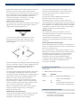
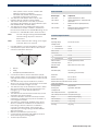
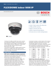
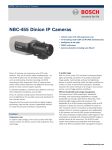
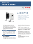
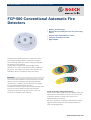
Fire Alarm Systems | FCP‑500 Conventional Automatic Fire Detectors
FCP‑500 Conventional Automatic Fire
Detectors
▶ Modern, ultra-flat design
▶ Matches the surrounding decor by using color toning
inserts
▶ Smooth, easily-cleaned detector surface
▶ Innovative fastening mechanism
▶ High reliability
FCP‑500 Conventional Automatic Fire Detectors satisfy
the most demanding aesthetic requirements owing to
their flat design, which offers flush ceiling mounting and
the option of color matching.
The FCP‑500 is available as a scattered light smoke
detector or as a multi-sensor detector with an additional
gas sensor. The respective versions of the detectors are
available in white or transparent with color inserts.
Functions
The smooth, flush-installation surface means the FCP‑500
detectors can be installed in areas with high aesthetic
requirements. In addition, the fire detectors are suitable
for areas with heightened dust exposure.
The detectors and trim rings in the "transparent with color
inserts" version are always supplied complete with
reversible printed color rings, which offer a choice of
16 colors for individual color matching.
Sensor technology and signal processing
All detectors in the FCP‑500 series are equipped with two
optical sensors and a pollution sensor. The FCP‑OC 500
multisensor detector contains a gas sensor as an
additional detection channel.
All sensor signals are constantly analyzed by the internal
signal evaluation electronics and are linked with each
other through algorithms.
www.boschsecurity.com
2 | FCP‑500 Conventional Automatic Fire Detectors
By linking the optical sensors and the gas sensor, the OC
detector can also be used in places where the work
carried out gives rise to small amounts of smoke, steam or
dust. The alarm will only be triggered automatically if the
signal combination corresponds with the detector’s
characteristic diagram. Consequently, a very high
reliability against false alarms is obtained.
Optical sensor (smoke sensor)
The optical sensor (1) operates according to the scattered
light method. The LEDs (3) transmit light at a defined
angle into the scattered light area (7).
2
3
The basic measuring principle is CO oxidation on an
electrode and the measurable current that arises from
this. The sensor signal value is proportional to the
concentration of gas.
The gas sensor delivers additional information to
effectively suppress deceptive values.
Depending on the service life of the gas sensor, the
FCP‑OC 500 detector switches off the C sensors after five
years of operation. The detector will continue to function
as an O detector. The detector should then be exchanged
immediately in order to be able to keep using the higher
reliability of detection of the OC detector.
Pollution sensor
The contamination level on the detector surface is
continually measured by the pollution sensor (6); the
result is evaluated and indicated.
7
In case of fire, the light is scattered by the smoke
particles and strikes the photo diodes (2), which
transform the quantity of light into a proportional
electrical signal.
3
5
6
1
3
Further performance characteristics
Various operating states are indicated on the detector by
means of a clearly visible two-color LED. In the event of an
alarm, the LED flashes red.
4
2
Contamination of the detector surface leads to active
adaptation of the threshold value (closed-circuit value
correction).
1
2
Interference effects from daylight and commercial lighting
sources are filtered out with an optical daylight filter and
by the use of electronic filtering and phase-locked
rectification (ambient light stability: glare test
DIN EN 54‑7).
The various light-emitting and photo diodes of the sensor
are individually controlled by the detector electronics.
Consequently, signal combinations are produced that are
independent of each other and ideally suitable for the
detection of smoke, which makes it possible to
differentiate between smoke and interference agents
(insects, objects). In addition, the time characteristics
and the correlation of the optical sensor signals for the
fire or interference detection are evaluated.
The innovative detector locking, which operates on the
ballpoint-pen principle, provides fast and simple insertion
and replacement of the detector. We recommend the
specially developed FAA‑500‑RTL exchanger device,
especially in the case of high installation heights.
To allow convenient detector testing, the FAA‑500‑TTL
test adapter with magnet and additional service
accessories is available.
Certifications and Approvals
Comply with:
•
EN54-7:2000/A1:2002/A2:2006
Region
Certification
Germany
VdS
G 205124 FCP-O 500/500-P
G 205118 FCP-OC 500/500-P
Europe
CE
FCP-500
CPD
0786-CPD-20203 FCP-O 500 / 500-P
0786-CPD-20204 FCP-OC500 / 500-P
Moreover, plausibility checking of the various signals
makes it possible to detect errors in the analysis
electronics and the LEDs.
Installation/Configuration Notes
Chemical sensor (CO gas sensor)
•
The gas sensor (4) detects mainly the carbon monoxide
(CO) that is produced by a fire, but it also detects
hydrogen (H) and nitrogen monoxide (NO).
Can be connected to:
- Conventional Fire Panel BZ 1012/1016/1024/1060
- Universal Fire Panel UEZ 1000
- Universal Fire Panel UGM 2020
FCP‑500 Conventional Automatic Fire Detectors | 3
-
Other panels or their receiver modules with
identical connection conditions
- UEZ 2000 LSN, BZ 500 LSN, FPA‑5000 and
FPA‑1200 via appropriate interfaces
The detectors and detector bases can be used
together with the „Rotaris” lamp by Philips.
The FCP‑OC 500, like the FCP‑O 500, is planned
according to the guidelines for optical detectors (see
DIN VDE 0833 Part 2 and VDS 2095).
The detectors must be installed exclusively in the
FCA‑500 bases provided. In addition, the detector
base must be installed in an FAA‑500‑BB ceiling mount
back box or in FAA‑500‑SB surface mount back box.
•
•
•
Note
Note
•
•
For flush ceiling mounting with FAA‑500‑BB:
The false ceiling may have a maximum
thickness of
32 mm. Above the false ceiling, a free height
of at least 110 mm is required.
FCP‑500 detectors are not intended for outdoor use.
A hemispherical space with a radius of 50 cm must
remain free below the detectors.
1
•
•
•
•
•
•
•
•
Qty.
Components
FCP-O 500
1
Optical Smoke Detector, White
FCP-O 500-P
1
Optical Smoke Detector, Transparent with
Color Inserts
FCP-OC 500
1
Multisensor Detector Optical/Chemical,
White
FCP-OC 500-P
1
Multisensor Detector Optical/Chemical,
Transparent with Color Inserts
Technical Specifications
Electrical
Operating voltage
8.5 V DC bis 33 V DC
Standby current
•
•
FCA-500-EU
3 mA
FCA-500-E-EU
24 mA
Alarm current
•
•
3
•
Detector type
47 mA
Fault current
50 cm
2
Parts Included
FCA-500-EU
52 mA
FCA-500-E-EU
58 mA
Alarm resistance
0 Ω (UL application) or 680 Ω
Fault relay output
NC / C
Indicator output
Relay connects 0 V over 1.5 kΩ
1
Detector
Mechanics
2
Ceiling
3
hemispherical space below the detector
Individual display
Care must be taken to ensure that neither people,
larger animals, plants nor any objects intrude into this
area and that no parts of the detector surface become
covered.
The detectors may only be installed in a position
which is out of arm's reach. We therefore recommend
a minimum installation height of 2.70 m.
The detectors may not be installed in rooms in which
data is transmitted by means of high-intensity infrared light (e. g. in rooms with IR systems for
interpreters).
The detectors must be mounted so that they are not
exposed to any direct sunlight.
A minimum distance of 50 cm from lamps must be
maintained. The detectors may not be mounted in a
cone of light from lamps.
The bases are equipped as standard with a spring
which is suitable for installation of the detector in
false ceilings. When the detector is installed in
concrete or wooden ceilings, these need to be
replaced by the stronger springs FAA‑500‑SPRING
with red markings.
Maximum permitted air speed: 20 m/s
Country-specific standards and guidelines must be
observed during the planning phase.
Technical Specifications
Two-color LED,
red (alarm), green (test mode)
Dimensions
Detector
Ø 113 x 55 mm
Detector with trim ring
Ø 150 x 55 mm
Detector with cover, base and Ø 150 x 110 mm
ceiling mount back box
Housing material
Polycarbonate
Housing color
Signal white, RAL 9003
Front plate color
FCP‑O 500/ FCP‑OC 500
Signal white matt
FCP‑O 500‑P/ FCP‑OC 500‑P Transparent/silver-gray
Weight
Without / with packaging
FCP-OC 500(-P)
180 g / 370 g
FCP-O 500(-P)
170 g / 360 g
Trim Ring
30 g / 60 g
www.boschsecurity.com
4 | FCP‑500 Conventional Automatic Fire Detectors
Environmental conditions
Ordering Information
Protection class as per
EN 60529
FCP‑O 500 (‑P)
IP 53
FCP‑OC 500 (‑P)
IP 33
Permissible operating temperature
FCP‑O 500 (‑P)
-20 °C bis +65 °C
FCP‑OC 500 (‑P)
-10 °C bis +50 °C
Permissible relative humidity 95% (non-condensing)
Permissible air speed
20 m/s
Planning
Monitoring area
Max. 120 m2
(Heed local guidelines!)
Maximum installation height
Max. 16 m
(Heed local guidelines!)
Minimum installation height
Out of arm's reach
Minimum installation height recommended by BOSCH: 2.70 m
In the case of flush ceiling
mounting with ceiling mount
back box
Thickness of the false ceiling
Max. 32 mm
Required bored hole
Ø 130 mm (-1 mm bis +5 mm)
Installation depth
110 mm
Note: Above the false ceiling, a free height
of at least 110 mm is required.
Minimum distance to lamps
0.5 m
Special features
Detection principle
•
•
FCP‑O 500 (‑P)
Scattered light measurement
FCP‑OC 500 (‑P)
Combination of scattered light measurement
and combustion gas measurement
Features
•
All FCP‑500 detec- Contamination detection
Drift compensation (optical section)
tors
•
In addition, for
FCP‑OC 500(-P)
Drift compensation in the gas sensor section
Response sensitivity
•
•
FCP‑O 500 (‑P)
< 0.18 dB/m ( EN 54‑7)
FCP‑OC 500 (‑P)
Optical section: < 0.36 dB/m (EN 54‑7)
Gas sensor section: in ppm range
FCP‑O 500 Optical Smoke Detector, White
ultra-flat design, conventional technology
FCP-O 500
FCP‑O 500‑P Optical Smoke Detector,
Transparent with Color Inserts
ultra-flat design, conventional technology
FCP-O 500-P
FCP‑OC 500 Multisensor Detector Optical/
Chemical, White
ultra-flat design, conventional technology
FCP-OC 500
FCP‑OC 500‑P Multisensor Detector
Optical/Chemical, Transparent with Color
Inserts
ultra-flat design, conventional technology
FCP-OC 500-P
Accessories
FAA‑500‑TR-W Trim Ring, White
for 500 and 520 Series Fire Detectors
FAA-500-TR-W
FAA‑500‑TR‑P Trim Ring, Transparent with
Color Inserts
for 500 and 520 Series Fire Detectors
FAA-500-TR-P
FCA‑500‑EU Conventional Base
for the FCP‑-500 Series detectors
FCA-500-EU
FCA‑500‑E‑EU Conventional Base EOL
for the FCP‑500 Series detectors, with integrated EOL resistor
FCA-500-E-EU
FAA‑500‑BB Ceiling Mount Back Box
for ceiling flush installation in false ceilings
when mounting 500 and 520 Series Bases
and Fire Detectors
FAA-500-BB
FAA‑500‑CB Built-in Housing for Concrete
Ceilings
for installing 500 and 520 Series Fire Detectors in concrete ceilings. In addition, you
need to order a FAA‑500‑BB Ceiling Mount
Back Box, which contains the base and the
detector.
FAA-500-CB
FAA‑500‑SB Surface Mount Back Box
for special applications where it is not possible to flush-mount the 500 and 520 Series
Fire Detectors in a ceiling
FAA-500-SB
FAA‑500‑SB-H Surface Mount Back Box
with Damp Room Seal
for special applications where it is not possible to flush-mount the 500 and 520 Series
Fire Detectors in a ceiling
FAA-500-SB-H
FAA‑500‑SPRING for Concrete/Wooden
Ceilings
(DU = 10 units)
FAA-500-SPRING
FCP‑500 Conventional Automatic Fire Detectors | 5
FCP-500 Conventional Automatic Fire Detectors
Detector type
Operating voltage
FCP-O 500
FCP-O 500-P
FCP-OC 500
FCP-OC 500-P
optical
optical
optical/chemical
optical/chemical
8.5 V DC . . . 33 V DC
8.5 V DC . . . 33 V DC
8.5 V DC . . . 33 V DC
8.5 V DC . . . 33 V DC
FCA-500-EU: 3 mA
FCA-500-E-EU: 24 mA
FCA-500-EU: 3 mA
FCA-500-E-EU: 24 mA
FCA-500-EU: 3 mA
FCA-500-E-EU: 24 mA
FCA-500-EU: 3 mA
FCA-500-E-EU: 24 mA
Current consumption
- Standby current
- Alarm current
47 mA
47 mA
47 mA
47 mA
- Fault current
FCA-500-EU: 52 mA
FCA-500-E-EU: 58 mA
FCA-500-EU: 52 mA
FCA-500-E-EU: 58 mA
FCA-500-EU: 52 mA
FCA-500-E-EU: 58 mA
FCA-500-EU: 52 mA
FCA-500-E-EU: 58 mA
IP 53
IP 53
IP 33
IP 33
-20 °C . . . +65 °C
-20 °C . . . +65 °C
-10 °C . . . +50 °C
-10 °C . . . +50 °C
Protection category
Permissible operating
temperature
max. 120 m²
max. 120 m²
max. 120 m²
max. 120 m²
Maximum installation
height
16 m
16 m
16 m
16 m
Color
white
transparent with color
inserts
white
transparent with color
inserts
Monitoring area
www.boschsecurity.com
6 | FCP‑500 Conventional Automatic Fire Detectors
Americas:
Bosch Security Systems, Inc.
130 Perinton Parkway
Fairport, New York, 14450, USA
Phone: +1 800 289 0096
Fax: +1 585 223 9180
[email protected]
www.boschsecurity.us
Europe, Middle East, Africa:
Bosch Security Systems B.V.
P.O. Box 80002
5600 JB Eindhoven, The Netherlands
Phone: + 31 40 2577 284
Fax: +31 40 2577 330
[email protected]
www.boschsecurity.com
© Bosch Security Systems 2011 | Data subject to change without notice
T1644324107 | Cur: en-US, V18, 29 Jun 2011
Asia-Pacific:
Robert Bosch (SEA) Pte Ltd, Security Systems
11 Bishan Street 21
Singapore 573943
Phone: +65 6258 5511
Fax: +65 6571 2698
[email protected]
www.boschsecurity.asia
Represented by