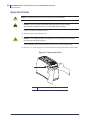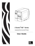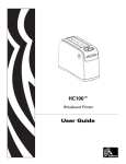
1
HC100™
Wristband Printer
Maintenance Manual
© 2008 ZIH Corp. The copyrights in this manual and the software and/or firmware in the label printer described
therein are owned by ZIH Corp. Unauthorized reproduction of this manual or the software and/or firmware in the
label printer may result in imprisonment of up to one year and fines of up to $10,000 (17 U.S.C.506). Copyright
violators may be subject to civil liability.
This product may contain ZPL®, ZPL II®, and ZebraLink™ programs; Element Energy Equalizer® Circuit; E3®; and
Monotype Imaging fonts. Software © ZIH Corp. All rights reserved worldwide.
ZebraLink and all product names and numbers are trademarks, and Zebra, the Zebra logo, ZPL, ZPL II, Element
Energy Equalizer Circuit, and E3 Circuit are registered trademarks of ZIH Corp. All rights reserved worldwide.
All other brand names, product names, or trademarks belong to their respective holders. For additional trademark
information, please see “Trademarks” on the product CD.
Proprietary Statement This manual contains proprietary information of Zebra Technologies Corporation and its
subsidiaries (“Zebra Technologies”). It is intended solely for the information and use of parties operating and
maintaining the equipment described herein. Such proprietary information may not be used, reproduced, or disclosed
to any other parties for any other purpose without the express, written permission of Zebra Technologies Corporation.
Product Improvements Continuous improvement of products is a policy of Zebra Technologies Corporation.
All specifications and designs are subject to change without notice.
Liability Disclaimer Zebra Technologies Corporation takes steps to ensure that its published Engineering
specifications and manuals are correct; however, errors do occur. Zebra Technologies Corporation reserves the right
to correct any such errors and disclaims liability resulting therefrom.
Limitation of Liability In no event shall Zebra Technologies Corporation or anyone else involved in the creation,
production, or delivery of the accompanying product (including hardware and software) be liable for any damages
whatsoever (including, without limitation, consequential damages including loss of business profits, business
interruption, or loss of business information) arising out of the use of, the results of use of, or inability to use such
product, even if Zebra Technologies Corporation has been advised of the possibility of such damages. Some
jurisdictions do not allow the exclusion or limitation of incidental or consequential damages, so the above limitation
or exclusion may not apply to you.
Part Number: 61311L-001 Rev. A
Contents
About This Document . . . . . . . . . . . . . . . . . . . . . . . . . . . . . . . . . . . . . . . . . . . . . . . 7
Who Should Use This Document . . . . . . . . . . . . . . . . . . . . . . . . . . . . . . . . . . . . . . . . . . . . 8
How This Document Is Organized . . . . . . . . . . . . . . . . . . . . . . . . . . . . . . . . . . . . . . . . . . . 8
Contacts . . . . . . . . . . . . . . . . . . . . . . . . . . . . . . . . . . . . . . . . . . . . . . . . . . . . . . . . . . . . . . . 9
Web Site . . . . . . . . . . . . . . . . . . . . . . . . . . . . . . . . . . . . . . . . . . . . . . . . . . . . . . . . . . . . 9
The Americas . . . . . . . . . . . . . . . . . . . . . . . . . . . . . . . . . . . . . . . . . . . . . . . . . . . . . . . . 9
Europe, Africa, Middle East, and India . . . . . . . . . . . . . . . . . . . . . . . . . . . . . . . . . . . . . 9
Asia Pacific . . . . . . . . . . . . . . . . . . . . . . . . . . . . . . . . . . . . . . . . . . . . . . . . . . . . . . . . . . 9
Document Conventions. . . . . . . . . . . . . . . . . . . . . . . . . . . . . . . . . . . . . . . . . . . . . . . . . . . 10
Related Documents . . . . . . . . . . . . . . . . . . . . . . . . . . . . . . . . . . . . . . . . . . . . . . . . . . . . . 12
1 • Introduction . . . . . . . . . . . . . . . . . . . . . . . . . . . . . . . . . . . . . . . . . . . . . . . . . . . 13
Overview . . . . . . . . . . . . . . . . . . . . . . . . . . . . . . . . . . . . . . . . . . . . . . . . . . . . . . . . . . . . . . 14
2 • Master Assembly Drawing . . . . . . . . . . . . . . . . . . . . . . . . . . . . . . . . . . . . . . . 15
Master Assembly Drawing . . . . . . . . . . . . . . . . . . . . . . . . . . . . . . . . . . . . . . . . . . . . . . . . 16
Maintenance Kits . . . . . . . . . . . . . . . . . . . . . . . . . . . . . . . . . . . . . . . . . . . . . . . . . . . . 16
5/8/08
HC100 Maintenance Manual
61311L-001 Rev. A
4
Contents
3 • Maintenance Kits . . . . . . . . . . . . . . . . . . . . . . . . . . . . . . . . . . . . . . . . . . . . . . . 19
61330M Printhead Assembly Maintenance Kit . . . . . . . . . . . . . . . . . . . . . . . . . . . . . . . . . . . . 20
Prepare for Installation . . . . . . . . . . . . . . . . . . . . . . . . . . . . . . . . . . . . . . . . . . . . . . . . . . .
Remove the Media Cartridge . . . . . . . . . . . . . . . . . . . . . . . . . . . . . . . . . . . . . . . . . . . . . .
Open the Printer . . . . . . . . . . . . . . . . . . . . . . . . . . . . . . . . . . . . . . . . . . . . . . . . . . . . . . . .
Remove the Printhead Assembly . . . . . . . . . . . . . . . . . . . . . . . . . . . . . . . . . . . . . . . . . . .
Install the New Printhead Assembly . . . . . . . . . . . . . . . . . . . . . . . . . . . . . . . . . . . . . . . . .
Resume Operation . . . . . . . . . . . . . . . . . . . . . . . . . . . . . . . . . . . . . . . . . . . . . . . . . . . . . .
20
21
23
25
28
29
61331M Platen Roller Assembly Maintenance Kit . . . . . . . . . . . . . . . . . . . . . . . . . . . . . . . . . . 30
Prepare for Installation . . . . . . . . . . . . . . . . . . . . . . . . . . . . . . . . . . . . . . . . . . . . . . . . . . .
Remove the Media Cartridge . . . . . . . . . . . . . . . . . . . . . . . . . . . . . . . . . . . . . . . . . . . . . .
Open the Printer . . . . . . . . . . . . . . . . . . . . . . . . . . . . . . . . . . . . . . . . . . . . . . . . . . . . . . . .
Reposition the Printhead Assembly . . . . . . . . . . . . . . . . . . . . . . . . . . . . . . . . . . . . . . . . .
Remove the Platen Roller . . . . . . . . . . . . . . . . . . . . . . . . . . . . . . . . . . . . . . . . . . . . . . . . .
Install the New Platen Roller. . . . . . . . . . . . . . . . . . . . . . . . . . . . . . . . . . . . . . . . . . . . . . .
Resume Operation . . . . . . . . . . . . . . . . . . . . . . . . . . . . . . . . . . . . . . . . . . . . . . . . . . . . . .
30
31
33
35
37
38
39
61335M Main Logic Board Maintenance Kit . . . . . . . . . . . . . . . . . . . . . . . . . . . . . . . . . . . . . . 40
Prepare for Installation . . . . . . . . . . . . . . . . . . . . . . . . . . . . . . . . . . . . . . . . . . . . . . . . . . .
Remove the Media Cartridge . . . . . . . . . . . . . . . . . . . . . . . . . . . . . . . . . . . . . . . . . . . . . .
Open the Printer . . . . . . . . . . . . . . . . . . . . . . . . . . . . . . . . . . . . . . . . . . . . . . . . . . . . . . . .
Remove the Outer Enclosure and Trim. . . . . . . . . . . . . . . . . . . . . . . . . . . . . . . . . . . . . . .
Remove the Old Main Logic Board (MLB) . . . . . . . . . . . . . . . . . . . . . . . . . . . . . . . . . . . .
Install the New MLB . . . . . . . . . . . . . . . . . . . . . . . . . . . . . . . . . . . . . . . . . . . . . . . . . . . . .
Reinstall the Outer Enclosure and Trim . . . . . . . . . . . . . . . . . . . . . . . . . . . . . . . . . . . . . .
Resume Printer Operation . . . . . . . . . . . . . . . . . . . . . . . . . . . . . . . . . . . . . . . . . . . . . . . .
40
41
43
45
48
55
57
58
61337M ZebraNet™ Internal Wireless Plus Print Server Assembly Kit . . . . . . . . . . . . . . . . 59
Prepare for Installation . . . . . . . . . . . . . . . . . . . . . . . . . . . . . . . . . . . . . . . . . . . . . . . . . . .
Remove the Media Cartridge . . . . . . . . . . . . . . . . . . . . . . . . . . . . . . . . . . . . . . . . . . . . . .
Open the Printer . . . . . . . . . . . . . . . . . . . . . . . . . . . . . . . . . . . . . . . . . . . . . . . . . . . . . . . .
Remove the Outer Enclosure and Trim. . . . . . . . . . . . . . . . . . . . . . . . . . . . . . . . . . . . . . .
Remove the Main Frame and the Main Logic Board (MLB) . . . . . . . . . . . . . . . . . . . . . . .
Remove the Wireless Radio Board. . . . . . . . . . . . . . . . . . . . . . . . . . . . . . . . . . . . . . . . . .
Install the New Wireless Board . . . . . . . . . . . . . . . . . . . . . . . . . . . . . . . . . . . . . . . . . . . . .
Reinstall the MLB . . . . . . . . . . . . . . . . . . . . . . . . . . . . . . . . . . . . . . . . . . . . . . . . . . . . . . .
Reinstall the Main Frame Assembly . . . . . . . . . . . . . . . . . . . . . . . . . . . . . . . . . . . . . . . . .
Reinstall the Outer Enclosure and Trim . . . . . . . . . . . . . . . . . . . . . . . . . . . . . . . . . . . . . .
Resume Printer Operation . . . . . . . . . . . . . . . . . . . . . . . . . . . . . . . . . . . . . . . . . . . . . . . .
61311L-001 Rev. A
HC100 Maintenance Manual
59
61
63
65
68
72
73
73
74
75
76
5/8/08
Contents
61338M ZebraNet™ 10/100 Print Server Assembly Maintenance Kit . . . . . . . . . . . . . . . . . . 77
Prepare for Installation . . . . . . . . . . . . . . . . . . . . . . . . . . . . . . . . . . . . . . . . . . . . . . . . . . .
Remove the Media Cartridge . . . . . . . . . . . . . . . . . . . . . . . . . . . . . . . . . . . . . . . . . . . . . .
Open the Printer . . . . . . . . . . . . . . . . . . . . . . . . . . . . . . . . . . . . . . . . . . . . . . . . . . . . . . . .
Remove the Outer Enclosure and Trim. . . . . . . . . . . . . . . . . . . . . . . . . . . . . . . . . . . . . . .
Access the Main Frame Assembly . . . . . . . . . . . . . . . . . . . . . . . . . . . . . . . . . . . . . . . . . .
Install the New 10/100 Print Server Board . . . . . . . . . . . . . . . . . . . . . . . . . . . . . . . . . . . .
Reinstall the Outer Enclosure and Trim . . . . . . . . . . . . . . . . . . . . . . . . . . . . . . . . . . . . . .
Resume Printer Operation . . . . . . . . . . . . . . . . . . . . . . . . . . . . . . . . . . . . . . . . . . . . . . . .
77
78
80
82
85
87
87
87
61339M Smart Card Reader Board Maintenance Kit . . . . . . . . . . . . . . . . . . . . . . . . . . . . . . . . 88
Prepare for Installation . . . . . . . . . . . . . . . . . . . . . . . . . . . . . . . . . . . . . . . . . . . . . . . . . . .
Remove the Media Cartridge . . . . . . . . . . . . . . . . . . . . . . . . . . . . . . . . . . . . . . . . . . . . . .
Open the Printer . . . . . . . . . . . . . . . . . . . . . . . . . . . . . . . . . . . . . . . . . . . . . . . . . . . . . . . .
Remove the Outer Enclosure and Trim. . . . . . . . . . . . . . . . . . . . . . . . . . . . . . . . . . . . . . .
Remove the Old Smart Card Reader . . . . . . . . . . . . . . . . . . . . . . . . . . . . . . . . . . . . . . . .
Install the New Smart Card Reader . . . . . . . . . . . . . . . . . . . . . . . . . . . . . . . . . . . . . . . . .
Reinstall the Outer Enclosure . . . . . . . . . . . . . . . . . . . . . . . . . . . . . . . . . . . . . . . . . . . . . .
Resume Printer Operation . . . . . . . . . . . . . . . . . . . . . . . . . . . . . . . . . . . . . . . . . . . . . . . .
88
89
91
93
96
97
97
98
61340M Upper Print Mechanism Cover Assembly Maintenance Kit . . . . . . . . . . . . . . . . . . . 99
Prepare for Installation . . . . . . . . . . . . . . . . . . . . . . . . . . . . . . . . . . . . . . . . . . . . . . . . . . . 99
Remove the Media Cartridge . . . . . . . . . . . . . . . . . . . . . . . . . . . . . . . . . . . . . . . . . . . . . 101
Open the Printer . . . . . . . . . . . . . . . . . . . . . . . . . . . . . . . . . . . . . . . . . . . . . . . . . . . . . . . 103
Remove the Outer Enclosure and Trim. . . . . . . . . . . . . . . . . . . . . . . . . . . . . . . . . . . . . . 105
Remove the Upper Print Mechanism Cover . . . . . . . . . . . . . . . . . . . . . . . . . . . . . . . . . . 108
Install the New Upper Print Mechanism Cover . . . . . . . . . . . . . . . . . . . . . . . . . . . . . . . . .110
Reinstall the Outer Enclosure and Trim . . . . . . . . . . . . . . . . . . . . . . . . . . . . . . . . . . . . . . 111
Resume Printer Operation . . . . . . . . . . . . . . . . . . . . . . . . . . . . . . . . . . . . . . . . . . . . . . . . 111
61341M Print Mechanism Chassis Assembly Maintenance Kit . . . . . . . . . . . . . . . . . . . . . . 112
Prepare for Installation . . . . . . . . . . . . . . . . . . . . . . . . . . . . . . . . . . . . . . . . . . . . . . . . . . .113
Remove the Media Cartridge . . . . . . . . . . . . . . . . . . . . . . . . . . . . . . . . . . . . . . . . . . . . . .115
Open the Printer . . . . . . . . . . . . . . . . . . . . . . . . . . . . . . . . . . . . . . . . . . . . . . . . . . . . . . . .117
Remove the Outer Enclosure and Trim. . . . . . . . . . . . . . . . . . . . . . . . . . . . . . . . . . . . . . .119
Remove the Upper Print Mechanism Cover . . . . . . . . . . . . . . . . . . . . . . . . . . . . . . . . . . 122
Remove the Print Mechanism Assembly . . . . . . . . . . . . . . . . . . . . . . . . . . . . . . . . . . . . 123
Install the New Print Mechanism Assembly . . . . . . . . . . . . . . . . . . . . . . . . . . . . . . . . . . 125
Reinstall the Upper Print Mechanism Cover . . . . . . . . . . . . . . . . . . . . . . . . . . . . . . . . . . 127
Reinstall the Outer Enclosure and Trim . . . . . . . . . . . . . . . . . . . . . . . . . . . . . . . . . . . . . 128
Resume Printer Operation . . . . . . . . . . . . . . . . . . . . . . . . . . . . . . . . . . . . . . . . . . . . . . . 128
5/8/08
HC100 Maintenance Manual
61311L-001 Rev. A
5
6
Contents
61342M Main Frame Assembly Kit . . . . . . . . . . . . . . . . . . . . . . . . . . . . . . . . . . . . . . . . . . . . . 129
Prepare for Installation . . . . . . . . . . . . . . . . . . . . . . . . . . . . . . . . . . . . . . . . . . . . . . . . . .
Remove the Media Cartridge . . . . . . . . . . . . . . . . . . . . . . . . . . . . . . . . . . . . . . . . . . . . .
Open the Printer . . . . . . . . . . . . . . . . . . . . . . . . . . . . . . . . . . . . . . . . . . . . . . . . . . . . . . .
Remove the Outer Enclosure and Trim. . . . . . . . . . . . . . . . . . . . . . . . . . . . . . . . . . . . . .
Remove the Main Frame and the Main Logic Board (MLB) . . . . . . . . . . . . . . . . . . . . . .
Remove the Upper Print Mechanism Cover . . . . . . . . . . . . . . . . . . . . . . . . . . . . . . . . . .
Remove the Print Mechanism Assembly . . . . . . . . . . . . . . . . . . . . . . . . . . . . . . . . . . . .
Remove the Smart Card Reader . . . . . . . . . . . . . . . . . . . . . . . . . . . . . . . . . . . . . . . . . .
Reinstall the MLB . . . . . . . . . . . . . . . . . . . . . . . . . . . . . . . . . . . . . . . . . . . . . . . . . . . . . .
Reinstall the Smart Card Reader . . . . . . . . . . . . . . . . . . . . . . . . . . . . . . . . . . . . . . . . . .
Reinstall the Main Frame Assembly . . . . . . . . . . . . . . . . . . . . . . . . . . . . . . . . . . . . . . . .
Reinstall the Upper Print Mechanism Cover . . . . . . . . . . . . . . . . . . . . . . . . . . . . . . . . . .
Resume Printer Operation . . . . . . . . . . . . . . . . . . . . . . . . . . . . . . . . . . . . . . . . . . . . . . .
129
131
133
135
138
142
143
144
146
147
149
150
151
61343M Outer Enclosure and Trim Maintenance Kit . . . . . . . . . . . . . . . . . . . . . . . . . . . . . . 152
Prepare for Installation . . . . . . . . . . . . . . . . . . . . . . . . . . . . . . . . . . . . . . . . . . . . . . . . . .
Remove the Media Cartridge . . . . . . . . . . . . . . . . . . . . . . . . . . . . . . . . . . . . . . . . . . . . .
Open the Printer . . . . . . . . . . . . . . . . . . . . . . . . . . . . . . . . . . . . . . . . . . . . . . . . . . . . . . .
Remove the Outer Enclosure and Trim. . . . . . . . . . . . . . . . . . . . . . . . . . . . . . . . . . . . . .
Reinstall the Outer Enclosure and Trim . . . . . . . . . . . . . . . . . . . . . . . . . . . . . . . . . . . . .
Resume Printer Operation . . . . . . . . . . . . . . . . . . . . . . . . . . . . . . . . . . . . . . . . . . . . . . .
61311L-001 Rev. A
HC100 Maintenance Manual
152
154
156
158
161
161
5/8/08
About This Document
This section provides you with contact information, document structure and organization, and
additional reference documents.
Contents
Who Should Use This Document . . . . . . . . . . . . . . . . . . . . . . . . . . . . . . . . . . . . . . . . . . . . 8
How This Document Is Organized . . . . . . . . . . . . . . . . . . . . . . . . . . . . . . . . . . . . . . . . . . . 8
Contacts . . . . . . . . . . . . . . . . . . . . . . . . . . . . . . . . . . . . . . . . . . . . . . . . . . . . . . . . . . . . . . . 9
Document Conventions . . . . . . . . . . . . . . . . . . . . . . . . . . . . . . . . . . . . . . . . . . . . . . . . . . 10
Related Documents . . . . . . . . . . . . . . . . . . . . . . . . . . . . . . . . . . . . . . . . . . . . . . . . . . . . . 12
5/8/08
HC100 Maintenance Manual
61311L-001 Rev. A
8
About This Document
Who Should Use This Document
Who Should Use This Document
This Maintenance Manual helps you quickly identify and maintain assemblies in the HC100.
How This Document Is Organized
The Maintenance Manual is set up as follows:
Section
Description
Technical Support
How to contact technical support.
Introduction
An introduction to the HC100.
Master Assembly Drawing
Identifies the assemblies and part names and kit numbers.
Installation Instructions
How to install replacement parts (also known as maintenance kits).
61311L-001 Rev. A
HC100 Maintenance Manual
5/8/08
About This Document
Contacts
Contacts
You can contact Zebra Technologies Corporation at the following:
Web Site
http://www.zebra.com
Technical Support via the Internet is available 24 hours per day, 365 days per year. Go to
http://www.zebra.com/support.
The Americas
Regional Headquarters
Technical Support
Customer Service Dept.
Zebra Technologies International,
LLC
333 Corporate Woods Parkway
Vernon Hills, Illinois 60061.3109
U.S.A
T: +1 847 793 2600
Toll-free +1 800 423 0422
F: +1 847 913 8766
T: +1 877 ASK ZEBRA (275 9327)
F: +1 847 913 2578
For printers, parts, media, and ribbon,
please call your distributor, or
contact us.
Hardware: [email protected]
Software: [email protected]
T: +1 877 ASK ZEBRA (275 9327)
E: [email protected]
Europe, Africa, Middle East, and India
Regional Headquarters
Technical Support
Internal Sales Dept.
Zebra Technologies Europe Limited
Zebra House
The Valley Centre, Gordon Road
High Wycombe
Buckinghamshire, HP13 6EQ, UK
T: +44 (0) 1494 768298
F: +44 (0) 1494 768210
Germany: [email protected]
France: [email protected]
Spain/Portugal: [email protected]
All other areas: [email protected]
For printers, parts, media, and ribbon,
please call your distributor, or
contact us.
Regional Headquarters
Technical Support
Customer Service
Zebra Technologies Asia Pacific, LLC
120 Robinson Road
#06-01 Parakou Building
Singapore 068913
T: +65 6858 0722
F: +65 6885 0838
T: +65 6858 0722
F: +65 6885 0838
E: China: [email protected]
All other areas:
[email protected]
For printers, parts, media, and ribbon,
please call your distributor, or
contact us.
T: +44 (0)1494 472872
F: +44 (0) 1494 450103
T: +44 (0) 1494 768316
F: +44 (0) 1494 768244
E: [email protected]
Asia Pacific
5/8/08
HC100 Maintenance Manual
T: +65 6858 0722
F: +65 6885 0836
61311L-001 Rev. A
9
10
About This Document
Document Conventions
Document Conventions
The following conventions are used throughout this document to convey certain information.
Alternate Color (online only) Cross-references contain hot links to other sections in this
guide. If you are viewing this guide online in .pdf format, you can click the cross-reference
(blue text) to jump directly to its location.
LCD Display Examples Text from a printer’s Liquid Crystal Display (LCD) appears in
Bubbledot ICG font.
Icons Used
Caution • Warns you of the potential for electrostatic discharge.
Caution • Warns you of a potential electric shock situation.
Caution • Warns you of a situation where excessive heat could cause a burn.
Caution • Advises you that failure to take or avoid a specific action could result in physical
harm to you.
Caution • (No icon) Advises you that failure to take or avoid a specific action could result in
physical harm to the hardware.
Important • Advises you of information that is essential to complete a task.
Note • Indicates neutral or positive information that emphasizes or supplements important
points of the main text.
Example • Provides an example, often a scenario, to better clarify a section of text.
Tools • Tells you what tools you need to complete a given task.
61311L-001 Rev. A
HC100 Maintenance Manual
5/8/08
About This Document
Document Conventions
Illustration Callouts Callouts are used when an illustration contains information that needs
to be labeled and described. A table that contains the labels and descriptions follows the
graphic. Figure 1 provides an example.
Figure 1 • Sample Figure with Callouts
1
2
1
2
5/8/08
Eject button
Pause/Feed button
HC100 Maintenance Manual
61311L-001 Rev. A
11
12
About This Document
Related Documents
Related Documents
The following documents might be helpful references:
Applicable Zebra Printer User Guide
ZPL II® Programming Guide
ZebraNet® 10/100 Internal Print Server User Guide
ZebraNet® Wireless User Guide
61311L-001 Rev. A
HC100 Maintenance Manual
5/8/08
1
Introduction
This chapter gives a brief overview of the HC100.
Contents
Overview . . . . . . . . . . . . . . . . . . . . . . . . . . . . . . . . . . . . . . . . . . . . . . . . . . . . . . . . . . . . . 14
5/8/08
HC100 Maintenance Manual
61311L-001 Rev. A
14
Introduction
Overview
Overview
The HC100 prints patient identification wristbands for use in hospitals, clinics, and other
healthcare facilities. The printer uses an enclosed media cartridge to deliver the wristbands
and even tracks the remaining number of wristbands inside the cartridge. Wristbands are
available in multiple sizes including adult, child, and infant. The HC100 is self-calibrating and
simple to use.
This manual may be used as a reference for maintaining the HC100 printers. The manual
includes installation instructions for all of the maintenance kits as well as assembly drawings,
parts lists, and required tools.
61311L-001 Rev. A
HC100 Maintenance Manual
5/8/08
2
Master Assembly Drawing
This chapter provides the master assembly drawing for all maintenance kits for the HC100.
Contents
Master Assembly Drawing . . . . . . . . . . . . . . . . . . . . . . . . . . . . . . . . . . . . . . . . . . . . . . . . 16
Maintenance Kits . . . . . . . . . . . . . . . . . . . . . . . . . . . . . . . . . . . . . . . . . . . . . . . . . . . . . 16
5/8/08
HC100 Maintenance Manual
61311L-001 Rev. A
16
Master Assembly Drawing
Master Assembly Drawing
Master Assembly Drawing
All information provided in Table 1 corresponds to the numbers shown in Figure 2. For
example, arrow 8 in the drawing is identifying the Main Logic Board assembly. According to
Table 1, Item 8 gives both, the name and the part number, for the kit assembly.
Maintenance Kits
Table 1 • Master Assembly Kits
Item
Kit Part Number
Assembly Name
1
61340M
61340M Upper Print Mechanism Cover Assembly
Maintenance Kit on page 99
2
61330M
61330M Printhead Assembly Maintenance Kit
on page 20
3
61331M
61331M Platen Roller Assembly Maintenance Kit
on page 30
4
61341M
61341M Print Mechanism Chassis Assembly
Maintenance Kit on page 112
5
61342M
61342M Main Frame Assembly Kit on page 129
6
61338M
61338M ZebraNet™ 10/100 Print Server Assembly
Maintenance Kit on page 77
7
61337M
61337M ZebraNet™ Internal Wireless Plus Print
Server Assembly Kit on page 59
8
61335M
61335M Main Logic Board Maintenance Kit
on page 40
61336M
9
61339M
61339M Smart Card Reader Board Maintenance Kit
on page 88
10
61343M
61343M Outer Enclosure and Trim Maintenance Kit
on page 152
Important • The printer base is not included in any kit and thus, appears gray in Figure 2.
61311L-001 Rev. A
HC100 Maintenance Manual
5/8/08
Master Assembly Drawing
Master Assembly Drawing
Figure 2 • Master Assembly Drawing
1
10
2
7
3
4
9
8
7
6
5
10
5/8/08
HC100 Maintenance Manual
61311L-001 Rev. A
17
18
Master Assembly Drawing
Master Assembly Drawing
Notes • ___________________________________________________________________
__________________________________________________________________________
__________________________________________________________________________
__________________________________________________________________________
__________________________________________________________________________
__________________________________________________________________________
__________________________________________________________________________
__________________________________________________________________________
__________________________________________________________________________
__________________________________________________________________________
61311L-001 Rev. A
HC100 Maintenance Manual
5/8/08
3
Maintenance Kits
This chapter provides the installation instructions, parts lists, and required tools for all of the
maintenance kits for the HC100.
Contents
61330M Printhead Assembly Maintenance Kit . . . . . . . . . . . . . . . . . . . . . . . . . . . . . . . . 20
61331M Platen Roller Assembly Maintenance Kit . . . . . . . . . . . . . . . . . . . . . . . . . . . . . . 30
61335M Main Logic Board Maintenance Kit . . . . . . . . . . . . . . . . . . . . . . . . . . . . . . . . . . 40
61337M ZebraNet™ Internal Wireless Plus Print Server Assembly Kit . . . . . . . . . . . . . . 59
61338M ZebraNet™ 10/100 Print Server Assembly Maintenance Kit . . . . . . . . . . . . . . . 77
61339M Smart Card Reader Board Maintenance Kit. . . . . . . . . . . . . . . . . . . . . . . . . . . . 88
61340M Upper Print Mechanism Cover Assembly Maintenance Kit . . . . . . . . . . . . . . . . 99
61341M Print Mechanism Chassis Assembly Maintenance Kit . . . . . . . . . . . . . . . . . . . 112
61342M Main Frame Assembly Kit . . . . . . . . . . . . . . . . . . . . . . . . . . . . . . . . . . . . . . . . 129
61343M Outer Enclosure and Trim Maintenance Kit . . . . . . . . . . . . . . . . . . . . . . . . . . . 152
5/8/08
HC100 Maintenance Manual
61311L-001 Rev. A
20
61330M Printhead Assembly Maintenance Kit
Prepare for Installation
61330M Printhead Assembly Maintenance Kit
Installation Instructions
This kit includes the parts and documentation necessary to install the printhead assembly in the
HC100™. Read these instructions thoroughly before installing this kit.
Prepare for Installation
Parts List
Before proceeding, verify that your kit contains the items for your printer listed below.
!
Item Qty Part Number
Description
Ref
1 61330M
2 in. Thermal Printhead Maintenance Kit
1
1
61259-12 2 in. Thermal Printhead
2
1
61248 Media Chute
3
1
61230 Printhead Lever Plate
Bold = Part available for purchase.
Italic = Part not available for purchase; listed and shown for reference only.
Figure 3 • Kit Contents
2
1
3
Tools Required
Tools • You need these tools to complete this procedure:
! Antistatic Wriststrap and Mat
! 47362* Zebra Preventive Maintenance Kit
* In place of the Preventive Maintenance Kit, you may use a clean swab dipped in a solution of isopropyl
alcohol (minimum 90%) and deionized water (maximum 10%).
61311L-001 Rev. A
HC100 Maintenance Manual
5/8/08
61330M Printhead Assembly Maintenance Kit
Remove the Media Cartridge
Remove the Media Cartridge
1. See Figure 4. Press Eject and remove the media cartridge.
Figure 4 • Media Cartridge, Eject Button, and HC100
1
2
1
2
Eject button
Media cartridge
2. Did the cartridge eject?
If…
Then…
Yes
a. Remove the media cartridge and set aside.
b. Go to Open the Printer on page 23.
No
a. Turn off (O) the power switch.
b. Turn on (l) the power and wait for the printer to power up completely.
c. Press Eject.
d. Continue with step 3.
5/8/08
HC100 Maintenance Manual
61311L-001 Rev. A
21
22
61330M Printhead Assembly Maintenance Kit
Remove the Media Cartridge
3. Did the cartridge eject this time?
If…
Then…
Yes
a. Remove the media cartridge and set aside.
b. Go to Open the Printer.
No
a. Turn off (O) the power switch.
b. Turn on (l) the power and wait for the printer to power up completely.
c. Press and hold Eject for six seconds.
d. Release Eject.
e. If the cartridge ejected, go to Open the Printer.
f. If the cartridge did not eject, continue with step 4.
4. Contact Technical Support. See Contacts on page 9.
61311L-001 Rev. A
HC100 Maintenance Manual
5/8/08
61330M Printhead Assembly Maintenance Kit
Open the Printer
Open the Printer
1.
Caution • Observe proper electrostatic safety precautions when handling
static-sensitive components such as circuit boards and printheads.
Connect yourself to an antistatic device.
2. Place the printer on the antistatic mat.
3.
Caution • Turn off (O) the printer before performing the following procedure.
Turn off (O) the printer.
4. See Figure 5. Press the upper cover release buttons located on both sides of the printer.
Figure 5 • Opening the HC100
1
1
5/8/08
Upper cover release button (one on each side)
HC100 Maintenance Manual
61311L-001 Rev. A
23
24
61330M Printhead Assembly Maintenance Kit
Open the Printer
5. See Figure 6. Raise the cover up and tilt it toward the back until it is almost resting on the
top of the printer.
Figure 6 • HC100 with Cover Open
1
2
1
2
61311L-001 Rev. A
Upper cover
Metal printhead lever plate
HC100 Maintenance Manual
5/8/08
61330M Printhead Assembly Maintenance Kit
Remove the Printhead Assembly
Remove the Printhead Assembly
Caution • Before touching the printhead assembly, discharge any built-up static electricity
by touching the metal back plate on the printer near the On/Off switch or by using an
antistatic wriststrap and mat.
Caution • Be careful not to touch the printhead with any tools. This could damage the
printhead.
Caution • The printhead may be hot and could cause severe burns. Allow the printhead to
cool.
1.
Caution • While performing any tasks near an open printhead, remove all rings,
watches, hanging necklaces, identification badges, or other metallic objects that could
touch the printhead.
See Figure 6. To release the printhead assembly, lift up on the metal printhead lever plate
along the front edge of the printhead assembly.
5/8/08
HC100 Maintenance Manual
61311L-001 Rev. A
25
26
61330M Printhead Assembly Maintenance Kit
Remove the Printhead Assembly
2. See Figure 7. Lift the printhead assembly up and pull it forward ensuring the snap tabs
underneath the printhead assembly are disengaged from the printer.
Figure 7 • Close-up of Printhead Assembly Parts
1
2
3
3
4
4
5
1
2
3
4
5
61311L-001 Rev. A
Metal printhead lever plate
Underside of printhead assembly
Snap tabs (2)
Chassis slots (2)
Media chute
HC100 Maintenance Manual
5/8/08
61330M Printhead Assembly Maintenance Kit
Remove the Printhead Assembly
3. See Figure 8. Gently remove all of the wires from the cable clips located at the back
outside edges of the printhead assembly.
Figure 8 • Close-Up View of Printhead Assembly
1
2
1
2
3
1
2
3
Cable clips (2)
Printhead assembly socket and connector (2)
Ground wire (green)
4. Disconnect the right and left printhead cables.
a.
Slide a fingernail between the back edge of the socket and the connector to gently pry
each side of the connector out.
b.
Grasp the connector and pull it completely out of the socket.
c.
Repeat step 4 for the other cable.
5. Disconnect the small green ground wire from the printhead.
6. Remove the printhead assembly and discard.
5/8/08
HC100 Maintenance Manual
61311L-001 Rev. A
27
28
61330M Printhead Assembly Maintenance Kit
Install the New Printhead Assembly
Install the New Printhead Assembly
Caution • Remove all jewelry that could come into contact with the printhead or other
printer parts.
1. See Figure 8. Reconnect the right and left printhead cables.
a.
Support the front edge of the socket with your fingernail.
b.
Align the connector with the socket.
c.
Gently pinch the connector and socket together.
d.
Repeat step 1 for the other cable.
2. Thread the cable wires through the cable clip on each side of the printhead assembly.
Be sure to include the green ground wire in the cable clip on the left side of the printhead.
3. Reconnect the green ground wire.
4. Clean the print line on the printhead.
a.
Use the swab from a Preventive Maintenance Kit (part number 47362) or a clean
swab dipped in a solution of isopropyl alcohol (minimum 90%) and deionized water
(maximum 10%).
b.
On the underside of the printhead assembly, wipe along the brown strip from end to
end.
c.
Allow the solution to evaporate.
5. See Figure 7. Align the snap tabs on the bottom of the media chute with the slots in the
printer chassis.
6. Press the back edge of the printhead assembly into the slots and then press on the metal
printhead lever plate to snap the printhead assembly into place.
61311L-001 Rev. A
HC100 Maintenance Manual
5/8/08
61330M Printhead Assembly Maintenance Kit
Resume Operation
Resume Operation
1. See Figure 6. To close the upper cover, rock the front edge down, push the cover toward
the back of the printer, and then push the cover down.
2. Turn on (l) the printer.
3. Insert the media cartridge into the printer.
5/8/08
HC100 Maintenance Manual
61311L-001 Rev. A
29
30
61331M Platen Roller Assembly Maintenance Kit
Prepare for Installation
61331M Platen Roller Assembly Maintenance
Kit
Installation Instructions
This kit includes the parts and documentation necessary to install the Platen Roller
Replacement Kit in the HC100™. Read these instructions thoroughly before installing this kit.
Prepare for Installation
Parts List
Before proceeding, verify that your kit contains the items for your printer listed below.
!
Item Qty Part Number
Description
Ref
1 61331M
Platen Roller Maintenance Kit
1
1
Platen Shaft
61241
2
2
Locking Platen Bearing
61232
3
1
02133 External E-Ring 0.188 in.
Bold = Part available for purchase.
Italic = Part not available for purchase; listed and shown for reference only.
Figure 9 • Kit Contents
2
2
61311L-001 Rev. A
1
HC100 Maintenance Manual
3
5/8/08
61331M Platen Roller Assembly Maintenance Kit
Remove the Media Cartridge
Tools Required
Tools • You need these tools to complete this procedure:
! Antistatic Wriststrap and Mat
! 47362* Zebra Preventive Maintenance
Kit
* In place of the Preventive Maintenance Kit, you may use a clean swab dipped in a solution of isopropyl
alcohol (minimum 90%) and deionized water (maximum 10%).
Remove the Media Cartridge
1. See Figure 10. Press Eject and remove the media cartridge.
Figure 10 • Media Cartridge, Eject Button, and HC100
1
2
1
2
5/8/08
Eject button
Media cartridge
HC100 Maintenance Manual
61311L-001 Rev. A
31
32
61331M Platen Roller Assembly Maintenance Kit
Remove the Media Cartridge
2. Did the cartridge eject?
If…
Then…
Yes
a. Remove the media cartridge and set aside.
b. Go to Open the Printer.
No
a. Turn off (O) the power switch.
b. Turn on (l) the power and wait for the printer to power up completely.
c. Press Eject.
d. Continue with step 3.
3. Did the cartridge eject this time?
If…
Then…
Yes
a. Remove the media cartridge and set aside.
b. Go to Open the Printer.
No
a. Turn off (O) the power switch.
b. Turn on (l) the power and wait for the printer to power up completely.
c. Press and hold Eject for six seconds.
d. Release Eject.
e. If the cartridge ejected, go to Open the Printer.
f. If the cartridge did not eject, continue with step 4.
4. Contact Technical Support. See Contacts on page 9.
61311L-001 Rev. A
HC100 Maintenance Manual
5/8/08
61331M Platen Roller Assembly Maintenance Kit
Open the Printer
Open the Printer
1.
Caution • Observe proper electrostatic safety precautions when handling
static-sensitive components such as circuit boards and printheads.
Connect yourself to an antistatic device.
2. Place the printer on the antistatic mat.
3.
Caution • Turn off (O) the printer before performing the following procedure.
Turn off (O) the printer.
4. See Figure 11. Press the upper cover release buttons located on both sides of the printer.
Figure 11 • Opening the HC100
1
1
5/8/08
Upper cover release button (one on each side)
HC100 Maintenance Manual
61311L-001 Rev. A
33
34
61331M Platen Roller Assembly Maintenance Kit
Open the Printer
5. See Figure 12. Raise the cover up and tilt it toward the back until it is almost resting on the
top of the printer.
Figure 12 • HC100 with Cover Open
1
2
1
2
61311L-001 Rev. A
Upper cover
Metal printhead lever plate
HC100 Maintenance Manual
5/8/08
61331M Platen Roller Assembly Maintenance Kit
Reposition the Printhead Assembly
Reposition the Printhead Assembly
Caution • Before touching the printhead assembly, discharge any built-up static electricity
by touching the metal back plate on the printer near the On/Off switch or by using an
antistatic wriststrap and mat.
Caution • Be careful not to touch the printhead with any tools. This could damage the
printhead.
Caution • The printhead may be hot and could cause severe burns. Allow the printhead to
cool.
1.
Caution • While performing any tasks near an open printhead, remove all rings,
watches, hanging necklaces, identification badges, or other metallic objects that could
touch the printhead.
See Figure 12. To release the printhead assembly, lift up on the metal printhead lever
plate along the front edge of the printhead assembly.
5/8/08
HC100 Maintenance Manual
61311L-001 Rev. A
35
36
61331M Platen Roller Assembly Maintenance Kit
Reposition the Printhead Assembly
2. See Figure 13. Lift the printhead assembly up and pull it forward ensuring the snap tabs
underneath the printhead assembly are disengaged from the printer.
Figure 13 • Closeup of Printhead Assembly Parts
1
2
3
3
4
4
5
1
2
3
4
5
Metal printhead lever plate
Underside of printhead assembly
Snap tabs (2)
Chassis slots (2)
Media chute
3. Stand the printhead assembly up and back against the upper cover. It will stay in this
position until moved.
61311L-001 Rev. A
HC100 Maintenance Manual
5/8/08
61331M Platen Roller Assembly Maintenance Kit
Remove the Platen Roller
Remove the Platen Roller
1. See Figure 14. To unlock the platen roller, rotate the green platen release tabs until they
are in a vertical position.
Figure 14 • Platen Roller Locked in Place
(Release tabs shown in locked position)
1
1
Platen release tabs (2)
2. See Figure 15. Pull both of the platen release tabs straight up.
Figure 15 • Platen Roller Unlocked
(Release tabs shown in unlocked position)
1
1
5/8/08
Platen release tabs (2)
HC100 Maintenance Manual
61311L-001 Rev. A
37
38
61331M Platen Roller Assembly Maintenance Kit
Install the New Platen Roller
3. See Figure 16. Remove the platen roller assembly and discard.
Figure 16 • Platen Roller Assembly
1
2
1
2
Platen release tabs (2)
Platen gear
Install the New Platen Roller
1.
Caution • Remove all jewelry that could come into contact with the printhead or other
printer parts.
See Figure 16. Holding both release tabs in a vertical position with the platen gear on the
left, drop the platen roller into place in the printer chassis.
2. To lock the platen roller, rotate the green platen release tabs down until they are pointed
toward the front of the printer.
3. Clean the print line on the printhead.
a.
Use the swab from a Preventive Maintenance Kit (part number 47362) or a clean
swab dipped in a solution of isopropyl alcohol (minimum 90%) and deionized water
(maximum 10%).
b.
On the underside of the printhead assembly, wipe along the brown strip from end to
end.
c.
Allow the solution to evaporate.
4. See Figure 13. To replace the printhead assembly, align the snap tabs on the bottom of the
media chute with the slots in the printer chassis.
Be careful not to touch the print line.
5. Press the back edge of the printhead assembly into the slots and then press on the metal
printhead lever plate to snap the printhead assembly into place.
61311L-001 Rev. A
HC100 Maintenance Manual
5/8/08
61331M Platen Roller Assembly Maintenance Kit
Resume Operation
Resume Operation
1. See Figure 12. To close the upper cover, rock the front edge down, push the cover toward
the back of the printer, and then push the cover down.
2. Turn on (l) the printer.
3. Insert the media cartridge into the printer.
5/8/08
HC100 Maintenance Manual
61311L-001 Rev. A
39
40
61335M Main Logic Board Maintenance Kit
Prepare for Installation
61335M Main Logic Board Maintenance Kit
Installation Instructions
This kit includes the parts and documentation necessary to install the Main Logic Board
(MLB) maintenance kit in the HC100 printer.
Read these instructions thoroughly before installing this kit.
Prepare for Installation
Parts List
Before proceeding, verify that your kit contains the items for your printer listed below.
!
Item Qty Part Number
Ref
Ref
1
1
61335M
61336M
Description
HC100 Main Logic Board (MLB), 8MB Maintenance Kit
HC100 Main Logic Board (MLB), 64MB
Maintenance Kit
Bold = Part available for purchase.
Italic = Part not available for purchase; listed and shown for reference only.
Figure 17 • Kit Contents
61311L-001 Rev. A
HC100 Maintenance Manual
5/8/08
61335M Main Logic Board Maintenance Kit
Remove the Media Cartridge
Tools Required
Tools • You need these tools to complete this procedure:
! Phillips Screwdriver Set
! Metric Open End Wrench Set
! Flat-blade Screwdriver Set
! Antistatic Wriststrap and Pad
! Metric Nutdriver Set
Remove the Media Cartridge
1. See Figure 18. Press Eject.
Figure 18 • Media Cartridge, Eject Button, and HC100
1
2
1
2
5/8/08
Eject button
Media cartridge
HC100 Maintenance Manual
61311L-001 Rev. A
41
42
61335M Main Logic Board Maintenance Kit
Remove the Media Cartridge
2. Did the cartridge eject?
If…
Then…
Yes
a. Remove the media cartridge and set aside.
b. Go to Open the Printer on page 43.
No
a. Turn off (O) the power switch.
b. Turn on (l) the power and wait for the printer to power up completely.
c. Press Eject.
d. Continue with step 3.
3. Did the cartridge eject this time?
If…
Then…
Yes
a. Remove the media cartridge and set aside.
b. Go to Open the Printer on page 43.
No
a. Turn off (O) the power switch.
b. Turn on (l) the power and wait for the printer to power up completely.
c. Press and hold Eject for six seconds.
d. Release Eject.
e. If the cartridge ejected, go to Open the Printer.
f. If the cartridge did not eject, continue with step 4.
4. Contact Technical Support. See Contacts on page 9.
61311L-001 Rev. A
HC100 Maintenance Manual
5/8/08
61335M Main Logic Board Maintenance Kit
Open the Printer
Open the Printer
Caution • A qualified service technician must perform this installation.
1.
Caution • Observe proper electrostatic safety precautions when handling
static-sensitive components such as circuit boards and printheads.
Connect yourself to an antistatic device.
2. Place the printer on the antistatic mat.
3.
Caution • Turn off (O) the printer and disconnect it from the power source before
performing the following procedure.
Turn off (O) the printer and disconnect the DC power cord and all data cables.
4. See Figure 19. Press the upper cover release buttons located on both sides of the printer.
Figure 19 • Opening the HC100
1
1
5/8/08
Upper cover release button (one on each side)
HC100 Maintenance Manual
61311L-001 Rev. A
43
44
61335M Main Logic Board Maintenance Kit
Open the Printer
5. See Figure 20. Raise the cover up and tilt it toward the back.
Figure 20 • HC100 with Cover Open
1
1
61311L-001 Rev. A
Upper cover
HC100 Maintenance Manual
5/8/08
61335M Main Logic Board Maintenance Kit
Remove the Outer Enclosure and Trim
Remove the Outer Enclosure and Trim
Note • Retain all parts removed during disassembly, unless otherwise directed.
1. See Figure 21. Remove the trim plate by pressing each tab toward the rear of the printer
with your fingers and then lifting the trim plate off.
Figure 21 • Remove the Trim Plate
1
2
2
1
1
2
5/8/08
Trim plate
Tabs
HC100 Maintenance Manual
61311L-001 Rev. A
45
46
61335M Main Logic Board Maintenance Kit
Remove the Outer Enclosure and Trim
2. Remove the two mounting screws.
Figure 22 • Remove the Mounting Screws
2
1
3
4
4
5
1
2
3
4
5
Outer enclosure
Outer enclosure mounting screws (2)
Upper print mechanism cover
Upper cover release buttons (2)
Base
3. Press the upper cover release buttons located on both sides of the printer and then lift the
outer enclosure slightly off of the base.
61311L-001 Rev. A
HC100 Maintenance Manual
5/8/08
61335M Main Logic Board Maintenance Kit
Remove the Outer Enclosure and Trim
4. See Figure 23. Pull the upper cover out of the printer, turn it on its side, and then pull the
outer enclosure off the printer.
Figure 23 • Remove the Outer Enclosure
1
6
2
5
3
4
3
1
2
3
4
5
6
5/8/08
Outer enclosure
Upper print mechanism cover
Upper print mechanism release buttons (2)
User interface cable
Mounting post
Ground wire
HC100 Maintenance Manual
61311L-001 Rev. A
47
48
61335M Main Logic Board Maintenance Kit
Remove the Old Main Logic Board (MLB)
Remove the Old Main Logic Board (MLB)
1. Do you have a wireless card installed?
If…
Then…
No
Continue with step 2.
Yes
a. See Figure 24. Disconnect the antenna cable from the antenna by removing
the antenna from the cable connector, and then removing the mounting nut
and lock washer securing the cable to the antenna bracket.
b. Remove the antenna cable from the antenna bracket.
c. Continue with step 2.
Figure 24 • Remove the Antenna Cable
1
6
2
3
4
5
1
2
3
4
5
6
61311L-001 Rev. A
Antenna mounting bracket
Lock washer
Mounting nut
Antenna
Antenna cable
Antenna cable connector
HC100 Maintenance Manual
5/8/08
61335M Main Logic Board Maintenance Kit
Remove the Old Main Logic Board (MLB)
2. Remove the main frame assembly from the base by prying the four tabs away from the
main frame and lifting it off of the base.
Figure 25 • Remove the Main Frame
3
4
2
3
3
1
3
1
2
3
4
Base
Main frame assembly
Tabs (4)
Main logic board (MLB)
3. Lay the main frame assembly on its side on the antistatic mat with the MLB facing up.
5/8/08
HC100 Maintenance Manual
61311L-001 Rev. A
49
50
61335M Main Logic Board Maintenance Kit
Remove the Old Main Logic Board (MLB)
4. See Figure 26. Disconnect all cables and ground wires from the MLB.
Figure 26 • Disconnect all Cables
J15
J14
J2
J1
J6
J10
J11
J19
J3
J7
J12
S1
J4
J8
J5
J9 J16
J1
J2
J3
J4
J5
J6
J7
J8
J9
61311L-001 Rev. A
Wireless board
Wired ethernet board
Platen motor
Transport motor
Lock eject
Serial port
USB port
Power input
Open
J10
J11
J12
J14
J16
J18
J19
S1
HC100 Maintenance Manual
J18
Lock pin sensor
Media sensor
Ground pins
Printhead
Smartcard reader
User interface
Thermistor
On/Off switch
5/8/08
61335M Main Logic Board Maintenance Kit
Remove the Old Main Logic Board (MLB)
5. See Figure 27. Remove the MLB by removing the four screws securing it, sliding it to the
rear off the guide post and then lifting it off.
Note • The print mechanism and upper cover have been removed for clarity. Your printer
will still have these assemblies attached.
Figure 27 • Remove the MLB
2
1
6
3
5
4
1
2
3
4
5
6
5/8/08
MLB
MLB mounting screws (4)
Main frame assembly
Mounting posts (4)
Guide post
Guide hole
HC100 Maintenance Manual
61311L-001 Rev. A
51
52
61335M Main Logic Board Maintenance Kit
Remove the Old Main Logic Board (MLB)
6. Which communication option is being used?
If you have a…
Then…
Wired Ethernet
a. See Figure 28. Remove the wired ethernet board by removing
the three mounting nuts.
b. Slide the wired ethernet board off of the standoffs.
c. Remove the three standoffs from the old MLB.
d. Go to Install the New MLB on page 55.
Wireless Ethernet
a. See Figure 29. Remove the three mounting screws, spacers, and
nuts.
b. Remove the wireless ethernet board by pulling it out of
connector J1 on the MLB.
Note • Leave the antenna cable connected to the wireless ethernet
board.
c. Go to Install the New MLB on page 55.
Serial or USB port Go to Install the New MLB on page 55.
61311L-001 Rev. A
HC100 Maintenance Manual
5/8/08
61335M Main Logic Board Maintenance Kit
Remove the Old Main Logic Board (MLB)
Figure 28 • Remove the Wired Ethernet Board
2
1
3
4
5
6
1
2
3
4
5
6
5/8/08
Wired Ethernet board
Mounting nuts (3)
Standoffs (3)
MLB
MLB bracket
Ethernet access hole
HC100 Maintenance Manual
61311L-001 Rev. A
53
54
61335M Main Logic Board Maintenance Kit
Remove the Old Main Logic Board (MLB)
Figure 29 • Remove the Wireless Ethernet Board
1
4
2
3
7
6
1
2
3
4
5
6
7
61311L-001 Rev. A
5
Mounting nuts (3)
J1
Spacers (3)
Antenna cable
Mounting screws (3)
Wireless board
MLB
HC100 Maintenance Manual
5/8/08
61335M Main Logic Board Maintenance Kit
Install the New MLB
Install the New MLB
1. Which communication option is being used?
If you have a…
Then…
Wired Ethernet
a. See Figure 28 on page 53. Install the three standoffs on the new
MLB.
b. See Figure 30. Remove the Ethernet cover plate from the MLB
bracket by removing the screw securing it.
c. Slide the wired ethernet board into the hole in the MLB bracket
and then onto the three standoffs.
d. Install the three mounting nuts.
e. Continue to step 2.
Wireless Ethernet
a. See Figure 29. Install the wireless board connector into J1 on
the MLB.
b. Slide a spacer under the wireless board as aligning it with a
mounting holes in the wireless board.
c. Insert one of the mounting screws through the mounting hole in
the wireless board and then through the spacer and the MLB.
d. Install one of the mounting nuts, but do not tighten at this time.
e. Repeat this procedure for the other two mounting screws and
then tighten the three mounting nuts.
f. Continue to step 2.
Serial or USB port Continue to step 2.
Figure 30 • Remove the Ethernet Cover
2
1
1
2
Mounting screw
Ethernet cover plate
2. See Figure 27 on page 51. Slide the new MLB under all the cable connectors previously
removed, while aligning the guide post on the rear of the main frame with the guide hole
in the MLB bracket.
3. Align the mounting holes of the MLB with the mounting posts on the main frame
assembly.
5/8/08
HC100 Maintenance Manual
61311L-001 Rev. A
55
56
61335M Main Logic Board Maintenance Kit
Install the New MLB
4. Install the four mounting screws from the maintenance kit.
5. Important • Ensure all cable connectors are fully seated ans all connector housings are
flush against the main logic board.
See Figure 26 on page 50. Reconnect all cable connectors.
6. See Figure 31. Reinstall the main frame assembly onto the base by aligning the two
positioning posts with the positioning holes in the base.
Figure 31 • Reinstall the Main Frame Assembly
1
2
3
2
2
1
2
3
61311L-001 Rev. A
Main frame assembly
Tabs
Positioning holes (2)
HC100 Maintenance Manual
5/8/08
61335M Main Logic Board Maintenance Kit
Reinstall the Outer Enclosure and Trim
7. Ensure that all wires are clear of all tabs and then press down until all tabs are engaged.
Reinstall the Outer Enclosure and Trim
1. Is there a wireless board installed?
If…
Then…
No
Continue with step 2.
Yes
a. See Figure 24 on page 48. Reinstall the antenna cable into the antenna
mounting bracket.
b. Reinstall the antenna.
c. Continue with step 2.
2. See Figure 32. Turn the upper print mechanism cover on its side as shown with the ground
wire to the rear of the mounting post and the user interface cable to the rear of the upper
print mechanism release button.
Figure 32 • Reinstall the Outer Enclosure and Trim
1
2
6
5
6
5
3
4
1
2
3
5/8/08
Outer enclosure
Upper print mechanism cover
Upper print mechanism release buttons (2)
HC100 Maintenance Manual
4
5
6
User interface cable
Mounting post
Ground wire
61311L-001 Rev. A
57
58
61335M Main Logic Board Maintenance Kit
Resume Printer Operation
3. Slide the outer enclosure over the print mechanism assembly while pressing the upper
print mechanism release buttons until they are inside the outer enclosure.
4. Slip the left and right upper print mechanism legs inside the edges of the outer enclosure
and ensure that the ground wire is still routed to the rear of the mounting post before it is
seated on the base.
5. Slide the cover down until aligned and seated into the base.
6.
Caution • When inserting self-threading screws, be careful to avoid cross-threading or
stripping the plastic holes.
Reinstall the two mounting screws.
7. See Figure 21 on page 45. Reinstall the outer trim plate by sliding the back edge in first
and then lowering the front edges until they snap in place.
Resume Printer Operation
1. See Figure 2 on page 2. To close the upper cover, rock the front edge down, push the cover
toward the back of the printer, and then push the cover down.
2. Reinstall the data cables and DC power cord.
3. Turn on (l) the printer.
4. Insert the media cartridge into the printer.
61311L-001 Rev. A
HC100 Maintenance Manual
5/8/08
61337M ZebraNet™ Internal Wireless Plus Print Server Assembly Kit
Prepare for Installation
61337M ZebraNet™ Internal Wireless Plus Print
Server Assembly Kit
Installation Instructions
This kit includes the parts and documentation necessary to install the ZebraNet ™ Internal Wireless
Plus Print Server in the HC100™. Read these instructions thoroughly before installing this kit.
Prepare for Installation
Parts List
Before proceeding, verify that your kit contains the items for your printer listed below.
! Item Qty Part Number
Ref
1
61337M
Description
ZebraNet Internal Wireless Plus Print Server Assembly
Maintenance Kit (Shown as a sub-assembly)
Spacer
PCBA Circuit Board, Radio 802.11G
Spacer, Radio Module
Screw, 2-56 x 7/16 Pan Head Phillips
Nut, Esna 2-56 SS NY-Lock Re OD
Bracket, Antenna Mounting
Antenna, 1 in. Stub 802.11G
PA Cable, Wireless Antenna
Washer, 1/4 Internal Lock
Nut, 1/4 36 Uns 2B Hex
1
39516
1
CQ17544-G1
3
BA17963-1
3
TH-SJ0306
3
TH-ZA0300
1
61305
1
39538
1
39519
1
39526
1
39527
Bold = Part available for purchase.
Italic = Part not available for purchase; listed and shown for reference only.
5/8/08
HC100 Maintenance Manual
61311L-001 Rev. A
59
60
61337M ZebraNet™ Internal Wireless Plus Print Server Assembly Kit
Prepare for Installation
Figure 33 • Kit Contents
1
Tools Required
Tools • You need these tools to complete this procedure:
! Phillips Screwdriver Set
! Flat-blade Screwdriver Set
! Adjustable Crescent Wrench (8 mm)
! Metric Nutdriver Set
! Antistatic Wriststrap and Mat
61311L-001 Rev. A
HC100 Maintenance Manual
5/8/08
61337M ZebraNet™ Internal Wireless Plus Print Server Assembly Kit
Remove the Media Cartridge
Remove the Media Cartridge
1. See Figure 34. Press Eject and remove the media cartridge.
Figure 34 • Media Cartridge, Eject Button, and HC100
1
2
1
2
Eject button
Media cartridge
2. Did the cartridge eject?
If…
Then…
Yes
a. Remove the media cartridge and set aside.
b. Go to Open the Printer on page 63.
No
a. Turn off (O) the power switch.
b. Turn on (l) the power and wait for the printer to power up completely.
c. Press Eject.
d. Continue with step 3.
5/8/08
HC100 Maintenance Manual
61311L-001 Rev. A
61
62
61337M ZebraNet™ Internal Wireless Plus Print Server Assembly Kit
Remove the Media Cartridge
3. Did the cartridge eject this time?
If…
Then…
Yes
a. Remove the media cartridge and set aside.
b. Go to Open the Printer on page 63.
No
a. Turn off (O) the power switch.
b. Turn on (l) the power and wait for the printer to power up completely.
c. Press and hold Eject for six seconds.
d. Release Eject.
e. If the cartridge ejected, go to Open the Printer on page 63.
f. If the cartridge did not eject, continue with step 4.
4. Contact Technical Support. See Contacts on page 9.
61311L-001 Rev. A
HC100 Maintenance Manual
5/8/08
61337M ZebraNet™ Internal Wireless Plus Print Server Assembly Kit
Open the Printer
Open the Printer
Caution • A qualified service technician must perform this installation.
1.
Caution • Observe proper electrostatic safety precautions when handling
static-sensitive components such as circuit boards and printheads.
Connect yourself to an antistatic device.
2. Place the printer on the antistatic mat.
3.
Caution • Turn off (O) the printer and disconnect it from the power source before
performing the following procedure.
Turn off (O) the printer and disconnect the DC power cord and all data cables.
4. See Figure 35. Press the upper cover release buttons located on both sides of the printer.
Figure 35 • Opening the HC100
1
1
5/8/08
Upper cover release button (one on each side)
HC100 Maintenance Manual
61311L-001 Rev. A
63
64
61337M ZebraNet™ Internal Wireless Plus Print Server Assembly Kit
Open the Printer
5. See Figure 36. Raise the cover up and tilt it toward the back.
Figure 36 • HC100 with Cover Open
1
1
61311L-001 Rev. A
Upper cover
HC100 Maintenance Manual
5/8/08
61337M ZebraNet™ Internal Wireless Plus Print Server Assembly Kit
Remove the Outer Enclosure and Trim
Remove the Outer Enclosure and Trim
Note • Retain all parts removed during disassembly, unless otherwise directed.
1. See Figure 37. Press each tab toward the rear to release.
2. To remove the trim plate, slide the entire trim plate assembly back slightly and lift off.
Figure 37 • Remove the Trim Plate
2
1
1
2
2
1
2
5/8/08
Trim plate
Tabs
HC100 Maintenance Manual
61311L-001 Rev. A
65
66
61337M ZebraNet™ Internal Wireless Plus Print Server Assembly Kit
Remove the Outer Enclosure and Trim
3. See Figure 38. Using a Phillips screwdriver, remove the two mounting screws.
Figure 38 • Remove the Mounting Screws
2
1
3
4
4
5
1
2
3
4
5
Outer enclosure
Enclosure mounting screws (2)
Upper print mechanism cover
Upper cover release buttons (2)
Base
4. Press the upper cover release buttons located on both sides of the printer and then lift the
outer enclosure slightly off of the base.
61311L-001 Rev. A
HC100 Maintenance Manual
5/8/08
61337M ZebraNet™ Internal Wireless Plus Print Server Assembly Kit
Remove the Outer Enclosure and Trim
5. See Figure 39. Pull the upper cover out of the printer, turn it on its side, and then pull the
outer enclosure off the printer.
Figure 39 • Remove the Outer Enclosure
1
8
7
6
2
6
3
5
3
4
1
2
3
4
5
6
7
8
5/8/08
Outer enclosure
Upper print mechanism cover
Upper print mechanism release buttons (2)
Main logic board (MLB)
User interface cable
Upper print mechanism arms (2)
Mounting post (2)
Ground wire
HC100 Maintenance Manual
61311L-001 Rev. A
67
68
61337M ZebraNet™ Internal Wireless Plus Print Server Assembly Kit
Remove the Main Frame and the Main Logic Board (MLB)
Remove the Main Frame and the Main Logic Board
(MLB)
1. See Figure 40. To remove the main frame assembly, pry all four of the white snap tabs
away from the main frame and lift it up and out of the base.
Note • In Figure 40, the print mechanism chassis and upper print mechanism cover have
been removed to improve the clarity of this figure. Your printer will still have these
assemblies attached.
Figure 40 • Remove the Main Frame
2
1
2
3
2
1
2
3
61311L-001 Rev. A
Main frame assembly
Tabs (4)
Base
HC100 Maintenance Manual
5/8/08
61337M ZebraNet™ Internal Wireless Plus Print Server Assembly Kit
Remove the Main Frame and the Main Logic Board (MLB)
2. Lay the main frame assembly on its side on the antistatic mat with the MLB facing up.
3. Disconnect the smart card reader cable from J16 on the MLB.
Note • Do not disconnect the remaining cables and ground wires from the MLB. The rest
of this procedure can be performed without removing the wires.
4. See Figure 41. Disconnect the wireless antenna.
5/8/08
a.
Unscrew the antenna from the end of the antenna cable connector.
b.
Using an adjustable crescent wrench, remove the nut and lock washer from the end of
the antenna cable connector.
c.
Remove the antenna cable from the antenna bracket.
d.
Remove the antenna bracket from the slot on the left side of the print mechanism
chassis.
e.
Discard all hardware and the antenna cable.
HC100 Maintenance Manual
61311L-001 Rev. A
69
70
61337M ZebraNet™ Internal Wireless Plus Print Server Assembly Kit
Remove the Main Frame and the Main Logic Board (MLB)
Figure 41 • Remove the Wireless Antenna
2
1
4
3
5
8
7
6
1
2
3
4
5
6
7
8
Antenna cable connector
Antenna bracket
Lock washer
Nut
Antenna
J16 connector
Wireless Plus Print Server board
Wireless cable
5. See Figure 42. Using a Phillips screwdriver, remove the MLB by removing the four
screws securing it.
6. Slide it to the rear and off of the guide post.
Note • In Figure 42, the print mechanism chassis and upper print mechanism cover have
been removed to improve the clarity of this figure. Your printer will still have these
assemblies attached.
61311L-001 Rev. A
HC100 Maintenance Manual
5/8/08
61337M ZebraNet™ Internal Wireless Plus Print Server Assembly Kit
Remove the Main Frame and the Main Logic Board (MLB)
Figure 42 • Remove the MLB
2
1
3
5
4
1
2
3
4
5
5/8/08
MLB
MLB mounting screws (4)
Main frame assembly
Guide post
Guide hole
HC100 Maintenance Manual
61311L-001 Rev. A
71
72
61337M ZebraNet™ Internal Wireless Plus Print Server Assembly Kit
Remove the Wireless Radio Board
Remove the Wireless Radio Board
1. See Figure 43. Remove and discard the three Phillips mounting screws, standoffs, and
nuts.
Figure 43 • Remove the Wireless Board
1
3
2
7
6
5
1
2
3
4
5
6
7
4
Mounting nuts (3)
Spacers (3)
Antenna cable
Mounting screws (3)
Wireless board
MLB
J1 connector
2. Remove and discard the wireless radio board by pulling it out of the J1 connector on the
MLB.
61311L-001 Rev. A
HC100 Maintenance Manual
5/8/08
61337M ZebraNet™ Internal Wireless Plus Print Server Assembly Kit
Install the New Wireless Board
Install the New Wireless Board
1. See Figure 43 on page 72. Install the wireless radio board connector into J1 on the MLB.
2. See Figure 42 on page 71. Slide a spacer under the wireless board aligning it with a
mounting hole in the wireless board.
a.
Insert one of the mounting screws through the mounting hole in the wireless board
and then through the spacer and the MLB.
b.
Install one of the mounting nuts on the back of the MLB, but do not tighten at this
time.
c.
Repeat step 2 for the other two mounting screws, spacers, and nuts.
d.
Tighten the three mounting nuts.
Reinstall the MLB
1. See Figure 42 on page 71. Slide the MLB onto the rear guide post of the new main frame
assembly.
2. Align the mounting holes of the MLB with the mounting posts on the main frame
assembly.
3.
Caution • When inserting self-threading screws, be careful to avoid cross-threading or
stripping the plastic holes.
Caution •
Reinstall the MLB on the main frame assembly using the four Phillips mounting screws
previously removed.
4. Reconnect the smart card reader cable to J16 on the MLB.
5. See Figure 41 on page 70. Reconnect the wireless antenna.
5/8/08
a.
Insert the antenna bracket into the slot on the left side of the print mechanism chassis.
b.
Insert the antenna cable into the antenna bracket.
c.
Replace the lock washer and nut on the end of the antenna cable and tighten the nut
using an adjustable crescent wrench.
d.
Screw the antenna into the end of the antenna cable connector.
HC100 Maintenance Manual
61311L-001 Rev. A
73
74
61337M ZebraNet™ Internal Wireless Plus Print Server Assembly Kit
Reinstall the Main Frame Assembly
Reinstall the Main Frame Assembly
1. See Figure 44. Reinstall the main frame assembly onto the base by aligning the two
positioning posts with the positioning holes in the base.
Figure 44 • Reinstall the Main Frame Assembly
1
2
3
2
2
4
3
1
2
3
4
Main frame assembly
Tabs (4)
Positioning holes (2)
Eject spring
2. Ensure that all wires are clear of all tabs and then press down until all tabs are engaged.
61311L-001 Rev. A
HC100 Maintenance Manual
5/8/08
61337M ZebraNet™ Internal Wireless Plus Print Server Assembly Kit
Reinstall the Outer Enclosure and Trim
Reinstall the Outer Enclosure and Trim
Important • Ensure all cable connectors are fully seated and all connector housings are flush
against the main logic board.
1. See Figure 39 on page 67. Turn the upper print mechanism cover on its side as shown with
the ground wire to the rear of the mounting post and the user interface cable to the rear of
the upper print mechanism release button.
2. Slide the outer enclosure over the print mechanism assembly while pressing the upper
print mechanism release buttons until they are inside the outer enclosure.
3. Slip the left and right upper print mechanism arms inside the edges of the outer enclosure.
Ensure that the ground wire is still routed to the rear of the mounting post before it is
seated on the base.
4. Slide the enclosure down until aligned and seated into the base.
5.
Caution • When inserting self-threading screws, be careful to avoid cross-threading or
stripping the plastic holes.
Caution •
See Figure 38 on page 66. Reinstall the two Phillips mounting screws.
6. See Figure 37 on page 65. To reinstall the trim plate, slide the back edge in first, lower the
front edges, and snap in place.
5/8/08
HC100 Maintenance Manual
61311L-001 Rev. A
75
76
61337M ZebraNet™ Internal Wireless Plus Print Server Assembly Kit
Resume Printer Operation
Resume Printer Operation
1. See Figure 36 on page 64. To close the upper cover, rock the front edge down, push the
cover toward the back of the printer, and then push the cover down.
2. Reinstall the data cables and DC power cord.
3. Turn on (l) the printer.
4. Insert the media cartridge into the printer.
61311L-001 Rev. A
HC100 Maintenance Manual
5/8/08
61338M ZebraNet™ 10/100 Print Server Assembly Maintenance Kit
Prepare for Installation
61338M ZebraNet™ 10/100 Print Server
Assembly Maintenance Kit
Installation Instructions
This kit includes the parts and documentation necessary to install the ZebraNet™ 10/100 Print
Server in the HC100™. Read these instructions thoroughly before installing this kit.
Prepare for Installation
Parts List
Before proceeding, verify that your kit contains the items for your printer listed below.
!
Item Qty Part Number
Description
Ref
1
2
3
1 61338M
HC100 10/100 Ethernet Maintenance Kit,
1
79501-013 HC100 Ethernet Option Printed Circuit Board Assembly
3
HW10460 Hex Nut, M3 x 2.4 x 5.5 mm (Qty. of 25)
3
HW79656 Standoff, M3 x 0.5 x 10 mm (Qty. of 12)
1
Cover, RJ45 (Not shown)
79671
N/A = Not available as a separate part (listed for identification purposes only).
Bold = Part available for purchase.
Italic = Part not available for purchase; listed and shown for reference only.
Figure 45 • Kit Contents
1
2
2
3
5/8/08
HC100 Maintenance Manual
3
61311L-001 Rev. A
77
78
61338M ZebraNet™ 10/100 Print Server Assembly Maintenance Kit
Remove the Media Cartridge
Tools Required
Tools • You need these tools to complete this procedure:
! Phillips Screwdriver Set
! Metric Nutdriver Set
! Antistatic Wriststrap and Mat
Remove the Media Cartridge
1. See Figure 46. Press Eject and remove the media cartridge.
Figure 46 • Media Cartridge, Eject Button, and HC100
1
2
1
2
Eject button
Media cartridge
2. Did the cartridge eject?
If…
Then…
Yes
a. Remove the media cartridge and set aside.
b. Go to Open the Printer on page 80.
No
a. Turn off (O) the power switch.
b. Turn on (l) the power and wait for the printer to power up completely.
c. Press Eject.
d. Continue with step 3.
61311L-001 Rev. A
HC100 Maintenance Manual
5/8/08
61338M ZebraNet™ 10/100 Print Server Assembly Maintenance Kit
Remove the Media Cartridge
3. Did the cartridge eject this time?
If…
Then…
Yes
a. Remove the media cartridge and set aside.
b. Go to Open the Printer on page 80
No
a. Turn off (O) the power switch.
b. Turn on (l) the power and wait for the printer to power up completely.
c. Press and hold Eject for six seconds.
d. Release Eject.
e. If the cartridge ejected, go to Open the Printer on page 80.
f. If the cartridge did not eject, continue with step 4.
4. Contact Technical Support. See Contacts on page 9.
5/8/08
HC100 Maintenance Manual
61311L-001 Rev. A
79
80
61338M ZebraNet™ 10/100 Print Server Assembly Maintenance Kit
Open the Printer
Open the Printer
Caution • A qualified service technician must perform this installation.
1.
Caution • Observe proper electrostatic safety precautions when handling
static-sensitive components such as circuit boards and printheads.
Connect yourself to an antistatic device.
2. Place the printer on the antistatic mat.
3.
Caution • Turn off (O) the printer and disconnect it from the power source before
performing the following procedure.
Turn off (O) the printer and disconnect the DC power cord and all data cables.
4. See Figure 47. Press the upper cover release buttons located on both sides of the printer.
Figure 47 • Opening the HC100
1
1
61311L-001 Rev. A
Upper cover release button (one on each side)
HC100 Maintenance Manual
5/8/08