1
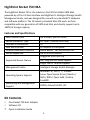
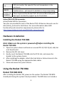
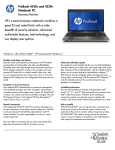
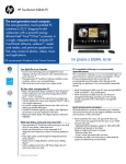
Rocket 750 40-Channel SATA 6Gb/s PCI-Express 2.0 x8 HBA Quick Installation Guide v1.0 Dec. 17, 2012 1 Table of Contents HighPoint Rocket 750 HBA ........................................................... 3 Kit Contents .................................................................................. 3 Board Layout ................................................................................ 4 Hardware Installation ................................................................... 6 Using the Rocket 750 HBA ............................................................ 6 Customer Support ........................................................................ 7 FCC Part 15 Class B Radio Frequency Interference Statement ..... 8 2 HighPoint Rocket 750 HBA The HighPoint Rocket 750 is the industry’s first 40-Port 6Gb/s SATA HBA, powered by a PCIe 2.0 host interface and HighPoint’s Intelligent Storage Health Management Suite, and was designed for use with any standard PC hardware and software platform. The 10 industry-standard Mini-SAS ports are fully compatible with any generation of SATA hard disk, and directly support up to 160TB of storage capacity. Features and Specifications Data Transfer Rate Device Connector Type Number of Connectors Host Bus Interface Onboard Indicators /Monitor Device Supported Supported Device Feature Up to 6Gb/s (per SFF-8087) SFF-8087 ( Internal Mini-SAS) 10 PCI Express 2.0 x8 speed Alarm Buzzer , Fail and Active LEDs Up to 40 SATA devices Staggered Drive Spin Up Hot-Plug and Hot-Swap support Larger than 2 TB drive support Management Suites Intelligent Storage Health Manager Operating System Support Windows: 8 / 2012 / 7 / 2008R2 Linux: Open Source Driver /Ubuntu / SLES / RHEL / Open SuSE / Fedora , FreeBSD Monitoring and Management Support SGPIO, Active/Fail LED, I2C Kit Contents One Rocket 750 Host Adapter Software CD Quick Installation Guide 3 Board Layout Rocket 750 PCB Board Layout A1-A10 Active LED J1 F1-F10 Failure LED BEEP1 Port10 Port9 Port8 Port7 Port6 Port5 Port4 Port3 Rocket 750 Port2 Port1 Connector and Jumper Description Disk Activity LED connector pins. A1-A10 4 A1 A2 A3 A4 A5 A6 A7 A8 A9 A10 P1 Drive1 Drive5 Drive9 Drive13 Drive17 Drive21 Drive25 Drive29 Drive33 Drive37 P2 Drive2 Drive6 Drive10 Drive14 Drive18 Drive22 Drive26 Drive30 Drive34 Drive38 P3 Drive3 Drive7 Drive11 Drive15 Drive19 Drive23 Drive27 Drive31 Drive35 Drive39 P4 Drive4 Drive8 Drive12 Drive16 Drive20 Drive24 Drive28 Drive32 Drive36 Drive40 P3 Drive3 Drive7 Drive11 Drive15 Drive19 Drive23 Drive27 Drive31 Drive35 Drive39 P4 Drive4 Drive8 Drive12 Drive16 Drive20 Drive24 Drive28 Drive32 Drive36 Drive40 Disk Failure LED connector pins. F1-F10 F1 F2 F3 F4 F5 F6 F7 F8 F9 F10 P1 Drive1 Drive5 Drive9 Drive13 Drive17 Drive21 Drive25 Drive29 Drive33 Drive37 P2 Drive2 Drive6 Drive10 Drive14 Drive18 Drive22 Drive26 Drive30 Drive34 Drive38 5 J1 I2C can monitor the speed of fan and temperature in the enclosure. BEEP1 Audible alarm – will sound if a disk fails or stops responding. PORT1 to PORT10 These represent the Rocket 750’s 10 Internal Mini-SAS ports. Each port can directly support up to 4 hard disks. Active/FAIL LED PIN connector: Active/Failed LED Pin Connectors Two pins are provided for each of the Rocket 750’s 40 device channels: one for disk activity, and one for disk failure. For more information about LED functionality and connection requirements, please refer to: http://www.highpoint-tech.com/PDF/LED_connection.pdf Hardware Installation Installing the Rocket 750 HBA Note: Make sure the system is powered-off before installing the Rocket 750 HBA. 1. 2. 3. 4. 5. Open the system chassis and locate an unused PCI-E (2.0/1.0) (x8, x16) slot or (3.0) (x16) slot. Remove the PCI slot cover. Gently insert the Rocket 750 HBA into the PCI-E slot, and secure the bracket to the system chassis. After installing the adapter, attach the hard disks or disk enclosure to the Rocket 750 HBA using the appropriate data cables. Close and secure the system chassis. Using the Rocket 750 HBA Rocket 750 HBA BIOS After installing the Rocket 750, power on the system. The Rocket 750 BIOS should post during the system’s boot procedure. The BIOS does not include a 6 management interface. The Rocket 750 and hosted devices can be managed at the operating system level, using the Intelligent Storage Health Manager interface. Driver and Software Installation (Windows) 1. 2. 3. 4. 5. 6. After installing the Rocket 750 host adapter, boot to the Windows operating system. Windows should automatically detect the card, and displays the “Found New Hardware Wizard”. Select “Locate and install driver software”. Select “Browse my computer for driver software”. Browse to the location of the driver and click “Next”. Reboot the system when prompted. The Rocket 750 host adapter will be ready for use after Windows reboots. Browse to the location of the HighPoint Intelligent Storage Health Manager Suite and double click the setup program to install. Please refer to the online help for storage set up through R750 Webpage: Global View, Physical, Settings, Event and SHI. http://www.highpoint-tech.com/help/ Driver and Software Installation (Linux and OS X) Please refer to the README file and Installation Guide under the driver folder for the appropriate installation procedure. Customer Support If you encounter any problems while utilizing the RocketRAID series HBA, or have any questions about this or any other HighPoint Technologies, Inc. product, feel free to contact our Customer Support Department. Web Support: http://www.highpoint-tech.com/websupport/ HighPoint Technologies, Inc. websites: http://www.highpoint-tech.com 7 FCC Part 15 Class B Radio Frequency Interference Statement This equipment has been tested and found to comply with the limits for a Class B digital device, pursuant to part 15 of the FCC Rules. These limits are designed to provide reasonable protection against harmful interference in a residential installation. This equipment generates uses and can radiate radio frequency energy and, if not installed and used in accordance with the instructions, may cause harmful interference to radio communications. However, there is no guarantee that interference will not occur in a particular installation. If this equipment does cause harmful interference to radio or television reception, which can be determined by turning the equipment off and on, the user is encouraged to try to correct the interference by one or more of the following measures: Reorient or relocate the receiving antenna. Increase the separation between the equipment and receiver. Connect the equipment into an outlet on a circuit different from that to which the receiver is connected. Consult the dealer or an experienced radio/TV technician for help. Modifications not expressly approved by the manufacturer could void the user’s authority to operate the equipment under FCC rules. This device complies with part 15 of the FCC Rules. Operation is subject to the following two conditions: (1) this device may not cause harmful interference, and (2) this device must accept any interference received, including interference that may cause undesired operation. European Union Compliance Statement This Information Technologies Equipment has been tested and found to comply with the following European directives: European Standard EN55022 (1998) Class B European Standard EN55024 (1998) © Copyright 2013 HighPoint Technologies, Inc. All right reserved. 8