1
T
ECHNICAL INFORMATION
Model No.
HR2450, HR2451, HR2452
Description
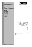
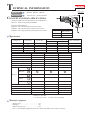
24mm (15/16 " ) Rotary Hammer
PRODUCT
P 1 / 16
L
CONCEPT AND MAIN APPLICATIONS
The above models are the advanced version of MAKITA's
famous 3 -modes rotary hammer HR2400.
Each new model features :
HR2450 : with variable speed and reverse switch
HR2451 : with variable switch without reverse switch
HR2452 : with single speed switch without reverse switch
Specification
Voltage (V)
Current (A)
110
120
220
230
240
7.5
6.7
3.7
3.6
3.4
Model No.
Power input : W
No load speed : (min -1= rpm)
Blows per min, :(bpm=min -1)
Single blow energy ( J )
Variable switch
Reverse switch
SDS max
Cycle (Hz)
50 / 60
50 / 60
50 / 60
50 / 60
50 / 60
H
W
Dimensions : mm ( " )
Length ( L ) 360 (14-1/8)
Height ( H ) 204 (8)
72 (2-13/16)
Width ( W )
Continuous Rating (W)
Input
Output
780
370
780
370
780
370
780
370
780
370
HR2450
HR2451
HR2452
780
0 - 1,100
0 - 4,500
2.7
Yes
Yes
780
0 - 1,100
0 - 4,500
2.7
Yes
No
780
1,100
4,500
2.7
No
No
Max. Output(W)
SDS
MAX
SDS plus
Bit type
SDS top
SDS
top
Spline
Hex
Max. diameter : mm (")
Max. core bit diameter: mm (")
* 24 (15/16 )
54 (2-1/8 )
* 24 (15/16 )
54 (2-1/8 )
* 24 (15/16 )
54 (2-1/8 )
Protection from electric shock by double insulation by double insulation by double insulation
** 4 (13.1)
** 4 (13.1)
** 4 (13.1)
Cord length : m ( ft )
2.4 (5.3)
2.4 (5.3)
2.4 (5.3)
Net weight :Kg (lbs )
* 25mm (1") for USA.
** 2.5m (8.2) for Asia
** 2.0m (6.6) for Australia
Standard equipment
* Stopper pole ........................................... 1 pc.
* Side grip ................................................. 1 pc.
* Plastic carrying case ............................... 1 pc.
< Note > The standard equipment for the tool shown may differ from country to country.
650
650
650
650
650
P 2 / 16
Repair
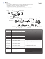
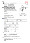
< 1 > Lubrication
Apply the following MAKITA grease to protect parts and product from unusual abrasion.
* Grease RA No.1 (Brown) to the portions marked with black triangle
* Grease FA No.2 to the portions marked with gray triangle
* Disulphide molybdenum alloyed grease to the portion marked with white triangle
Gear housing
Cap 35
Needle baring
Change lever
Piston joint
Steel ball 7.0
O ring 17
Tool holder
Inner housing
O ring 68
Piston cylinder
Spur gear 51
Spur gear 10
Clutch cam
Cam shaft
Cap 35
Grease RA No.1 (Brown)
Gear housing
Grease RA No.1 (Brown) : 60g
Needle bearing
Change lever
O ring 17
Grease RA No.1 (Brown)
Grease RA No.1 (Brown)
Grease RA No.1 (Brown)
Spur gear 51
Grease RA No.1 (Brown)
Steel ball 7.0
Grease RA No.1 (Brown)
Tool holder
Grease RA No.1 (Brown)
Piston cylinder
Grease RA No.1 (Brown)
O ring 68
Grease RA No.1 (Brown)
Inner housing
Grease RA No.1 (Brown)
Spur gear 10
Grease RA No.1 (Brown)
Clutch cam
Grease RA No.1 (Brown)
Disulphide molybdenum alloyed grease
Swash bearing 10
Grease FA No.2
Helical gear 26
Grease FA No.2
Swash bearing
Helical gear 26
Inner lip of bit inserting side
Inner portion where the mechanical parts are installed.
Groove for O ring 17 assembling portion
Inner ring
Top of the pins
Whole part
Inner portion where tool holder contacts
Convex portion of cam
Whole part
Inner portion where piston cylinder contacts
The portion where inner housing contacts
Inner portion where striker contacts
The portion where piston joint is assembled
Whole part
Inner portion where tool holder contacts
The groove where O ring 68 is assembled
Spiral portion
The hole where cam shaft contacts
Convex portion of cam
Whole of groove portion
Inner portion where cam shaft contacts
The surface where helical gear 26 contacts
The portion where balls are installed
Convex portion of cam
Whole of teeth portion
P 3 / 16
Repair
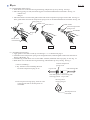
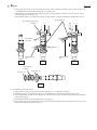
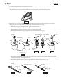
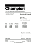
< 2 > Disassembling chuck section
1. Slide chuck cover in the direction of gear housing, and pull out cap 35 by turning. See Fig. 1.
2. Take off ring spring 19. Then, the following parts can be disassembled from tool holder. See Fig. 1A.
* Chuck cover
* Ring 21
3. Take off steel ball 7.0 with which guide washer and conical compression spring 21-29 are held. See Fig. 1A.
Then, guide washer and conical compression spring 21-29 can be disassembled from tool holder. See Fig. 1B.
Cap 35
Ring spring 19
Chuck cover
Guide washer
Steel ball 7.0
Conical compression
spring 21-29
Tool holder
Ring 21
Chuck cover
Gear housing
Fig. 1
Fig. 1A
Fig. 1B
< 3 > Assembling chuck section
1. Apply grease to steel ball 7.0 and cap 35 referring to < 1 > Lubrication at page 2.
2. Assemble conical compression spring 21-29 and guide washer, and hold guide washer with steel ball 7.0.
See Fig. 1B and Fig. 1A.
3. Assemble ring 21 and chuck cover to tool holder. And then, hold them with ring spring 19. See Fig. 1A.
4. Slide chuck cover in the direction of gear housing, and assemble cap 35 by turning. See Fig. 1.
< Note in assembling >
A. Pay attention to the assembling direction
of conical compression spring 21-29.
Conical compression
spring 21-29
Cap 35 side
Gear housing side
The small portion : Gear housing side
The large portion : Cap 35 side
B. The cut portion of ring spring 19 has to come
to the opposite side of the flat portion of
tool holder.
The cut portion
of ring spring 19
The flat portion of
tool holder.
Repair
P 4 / 16
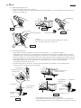
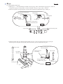
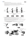
< 4 > Disassembling change lever
1. Separate cap from change lever. See Fig. 1.
2. Fully turn change lever in the direction of drill mode. Then, change lever can be pulled out from gear housing.
See Fig. 2A and Fig. 2B
Gear housing
Cap
Fig. 2
Gear housing
Fig. 2A
O ring 17
Lock button
Compression spring 3
Fig. 2B
Change lever
Cap
< Note >
Be careful, not to lose lock button and compression spring 3.
They can easily spring off. See Fig. 2C.
Gear housing
Fig. 2C
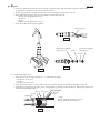
< 5 > Assembling change lever
1. Apply grease to the pin of change lever and O ring 17 referring to < 1 > Lubrication at page 2.
2. Assemble compression spring 3 and lock button to change lever. And temporarily assemble cap to the position
illustrated in Fig. 3 in order to stop springing off of lock button. Do not forget to assemble O ring 17. See Fig. 3.
3. Insert the change lever in which compression spring 3 and lock button have been temporarily fixed with cap, into
the assembling hole of gear housing. See Fig. 3A. The change lever can not be inserted completely in this stage.
4. Pressing the change lever, turn it in the direction of drill mode. Then, it can be inserted completely
in any position of area B. See Fig. 3B.
5. Turn the change lever to the area C. See Fig. 3B. And assemble cap completely to the original position
of change lever, by pressing to gear housing side.
Lock button
Compression spring 3
A
Change lever
Insert the change lever
within the area A.
Cap
Fig. 3A
O ring 17
C
Cap assembled
completely by
pressing.
Lock button
Lock button
Cap assembled
temporarily
Compression
spring 3
Change lever
Fig. 3
B
Compression
spring 3
Change lever
Fig. 3B
If the change lever can not be inserted completely
in any position of area B, pressing lock button, turn it to the direction
of drill mode again in order to insert completely in any position of area B.
Repair
P 5 / 16
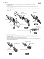
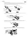
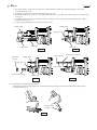
< 6 > Disassembling armature
1. Disassemble handle cover by unscrewing tapping screw 4 x 25. And disassemble carbon brushes
as illustrated in Fig. 4.
2. Separate gear housing together with armature, from motor housing by unscrewing tapping screws 4 x 45
as illustrated in Fig. 4A.
3. Slightly hitting the edge of gear housing with plastic hammer, remove armature from inner housing assembled in
gear housing. See Fig. 4B.
4. Ball bearings of fan side and commutator side can be disassembled with No.1R269 "Bearing extractor (small)".
See Fig. 4C.
Tapping s
crew 4 x 45 : 4 pcs.
Gear housing
Inner housing
Gear housing
Brush holder
Brush holder
Motor housing
Carbon brush
Plastic hammer
Carbon brush
Tapping s
crew 4 x 25 : 3 pcs.
Handle
cover
Fig. 4
Fig. 4B
Ball bearing
Armature
Fig. 4A
No.1R269 "Bearing extractor (small)"
Fig. 4C
< 7> Disassembling tool holder section
1. Disassemble change lever from gear housing as mentioned in < 4 > Disassembling change lever at page 4.
2. Separate gear housing from motor housing as illustrated in Fig. 4 and Fig. 4A. And disassemble armature as
illustrated in Fig. 4B.
3. Disassemble inner housing from gear housing as illustrated in Fig. 5.
4. Separate tool holder section from inner housing as illustrated in Fig. 5A. Pay attention, not to lose flat washer 28,
when separating tool holder section.
Tool holder section
Piston cylinder
Tool holder section
Inner housing
Inner housing
Plastic hammer
Flat washer 28
Swash bearing section
Swash bearing section
Fig. 5
Fig. 5A
P 6 / 16
Repair
5. Ring spring 28 can not be removed without pressing washer 30 down to the spur gear 51 side, because it is
assembled between tool holder and washer 30. See Fig. 5B.
6. Disassemble ring spring 28 with retaining ring plier, pressing washer 30 down to the spur gear 51 side as
illustrated in Fig. 5C and Fig. 5D.
7. Disassemble washer 30, compression spring 31 and spur gear 51 from tool holder as illustrated in Fig. 5E.
Ring spring 28
No. 1R306 Ring spring
extractor
Round bars
for arbor
Washer 30
Retaining ring
plier
Retaining ring
plier
Fig. 5B
Fig. 5C
Fig. 5D
Compression
spring 31
Spur gear 51
Washer 30
Fig. 5E
< 8 > Assembling tool holder section
1. Apply grease to spur gear 51 and tool holder referring to < 1 > Lubrication at page 2.
2. Assemble spur gear 5, compression spring 31 and washer 30 to tool holder as illustrated in Fig. 5E.
3. Pressing the washer 30 down to the spur gear 51 side, with arbor press, assemble ring spring 28 as illustrated
in Fig. 5D and Fig.5C.
4. Assemble flat washer 28 as illustrated in Fig. 5A at page 5.
5. Insert piston cylinder of swash bearing section into tool holder. And assemble tool holder section by pressing
into inner housing as illustrated in fig. 5A.
P 7 / 16
Repair
< 9 > Disassembling impact bolt
1. Referring to < 7 > Disassembling tool holder section at page 5 and 6, disassemble ring spring 28, washer 30,
compression spring 31 and spur gear 51 from tool holder. See Fig. 5, Fig. 5A, B, C, D and E.
2. Push the cut portion of ring spring 28 to the out side of the hole as illustrated in Fig. 6 and Fig. A.
Ring spring 28 showing its
cut portion
Ring spring
Inner
housing side
Cap 35 side
O ring case
O ring case
Push the cut portion to
the out side of the hole.
Fig. 6
Fig. 6A
Cap 35 side
Inner housing side
3. Hold tool holder with "No.1R038 Armature holder" and vise. Insert screwdriver between ring spring 28
and O ring case. and push out ring spring 28 from the inner groove as illustrated in Fig. 6B.
Cap 35 side
No.1R038
Armature holder
Push out ring spring 28 from
the inner groove.
Inner groove of
tool holder
Cap 35 side
O ring case
Ring spring 28
off from inner groove
Inner
housing side
Fig. 6B
Vise
Inner
housing side
Repair
P 8 / 16
4. Insert "No.1R236 Round bar for arbor" and push ring spring 28 as deep as possible to the inner housing side
by striking the round bar for arbor as illustrated in Fig. 6C.
5. Pick up ring spring 28 with plier and take off it from tool holder as illustrated in Fig. 6D.
6. Disassemble the following parts from tool holder as illustrated in Fig. 6E.
* O ring case equipped with O ring 9
* O ring 15
* Ring 9
* Impact bolt equipped with O ring 12
7. Clean the inside of tool holder completely.
Ring spring 28
Fig. 6D
Impact bolt equipped
with O ring 12
Ring 9
O ring case equipped
with O ring 9
O ring 15
Fig. 6E
Fig. 6C.
< 10 > Assembling impact bolt
1. Apply grease to the O rings referring to < 1 > Lubrication at page 2
* O ring 9 for O ring case
* O ring 15
* O ring 12 for impact bolt
2. Insert impact bolt, ring 9, O ring 15 and O ring case with O ring 9 into tool holder as illustrated in Fig. 6E.
3. Assemble ring spring 28 to the inner groove of tool holder by pushing it with screwdriver. Ring spring 28 has to be
assembled as illustrated in Fig. 7.
Ring spring 28
Ring 9 O ring 15
O ring case
O ring 12
O ring 9
Impact bolt
< Note >
Do not install the used ring spring 28.
Always assemble the fresh one.
Fig. 7
Repair
P 9 / 16
< 12 > Disassembling swash bearing
1. Referring to at page 5, disassemble the product in the order of Fig.4, Fig.4A and Fig.4B at page 5.
And separate inner housing together with tool holder section and swash bearing section from gear housing as
illustrated in Fig. 8C. Ball baring 606ZZ can remain in gear housing in this stage. If so, refer to Fig. 8H at page 10.
2. Separate tool holder section from inner housing as illustrated in Fig. 8D.
Tool holder section
Piston cylinder
Tool holder section
Inner housing
Plastic
hammer
Inner housing
Flat washer 28
*Ball bearing 606ZZ
Swash bearing section
Swash bearing section
Fig. 8C
Fig. 8D
3. Disassemble stop ring E-4, flat washer 5 and compression spring 6 with which change plate is fixed, from the pin
of inner housing as illustrated in Fig. 8E.
Piston cylinder
Stop ring E-4
Fat washer 5
Compression spring 6
Pin of inner housing
Change plate
Inner housing
Fig. 8E
4. Swash bearing section is held in inner housing with bearing retainer which is fastened with 2 pcs. of hex socket
head bolts M4x12. Take off these hex socket head bolts M4x12 for disassembling swash bearing section.
Hex socket head bolts M4x12
Fig. 8F
5. Bring piston cylinder to the dead point. And , twist the the swash bearing section, with pulling off them
from inner housing. Then swash bearing section and change plate can be disassembled from piston cylinder.
See Fig. 8G.
Piston cylinder
Change plate
Fig. 8G
Repair
P 10 / 16
6. Reassemble swash bearing section temporarily to gear housing, and hold gear housing as illustrated in Fig. 8H.
So, swash bearing section tilts in the direction of arrow.
Keeping the illustrated position, disassemble swash bearing section by striking the edge of gear housing
with plastic hammer. So, ball bearing 606ZZ can be removed together with swash bearing section.
Fig. 8H
7. Swash bearing section can not be disassembled in one action by pressing cam shaft with arbor press, because
retaining ring S-7 is assembled between ball bearing 608ZZ and compression spring 7.
Take the following steps for disassembling them.
1. Disassemble ring 8 by pressing with arbor press as illustrated in Fig. 9.
2. Disassemble ball bearing 608ZZ with bearing extractor as illustrated in Fig. 9A.
3. Disassemble flat washer 8 and bearing retainer as illustrated in Fig. 9B.
4. Disassemble helical gear 26 by pressing with arbor press as illustrated in Fig. 9C.
1R236 Round bar
for arbor
Bearing retainer
1R022 Bearing
extractor plate
Ring 8
Flat washer 8
1R236 Round bar
for arbor
Helical
gear 26
Ring 8
Ball bearing
608ZZ
1R023 Bearing
extractor ring
Fig. 9A
Fig. 9B
Fig. 9C
Fig. 9
5. Disassemble swash bearing 10 and clutch cam as illustrated in Fig. 9D. And disassemble ball bearing 606ZZ
with bearing extractor as illustrated in Fig. 9D.
6. Disassemble retaining ring S-7 with retaining ring plier as illustrated in Fig. 9E.
7. Separated compression spring 7 and spur gear 10 from cam shaft as illustrated in Fig. 9F.
Swash
bearing 10
Retaining ring S-7
Cam shaft
Spur gear 10
Clutch cam
Compression
spring 7
Ball bearing
606ZZ
Fig. 9D
Fig. 9E
Fig. 9F
Repair
P 11 / 16
< 13 > Assembling swash bearing section
1. Apply grease to the parts of swash bearing section referring to < 1 > Lubrication at page 2.
2. Assemble swash bearing 10 by pressing cam shaft with arbor press as illustrated in Fig. 10.
3. Assemble helical gear 26 by pressing cam shaft with arbor press as illustrated in Fig. 10A.
4. Assemble flat washer 8, bearing retainer and ball bearing 608ZZ by pressing cam shaft with arbor press
as illustrated in Fig. 10B.
5. Assemble ring 8 by pressing cam shaft with arbor press as illustrated in Fig. 10C.
Cam shaft
Flat washer 8
Swash
bearing 10
Bearing
retainer
Helical
gear 26
Ball bearing
608ZZ
Ring 8
No.1R034
Bearing setting plate
Fig. 10
Fig. 10A
Fig. 10B
Fig. 10C
< 14 > Assembling swash bearing section to piston cylinder
1. Apply MAKITA grease to piston cylinder and swash bearing 10 referring to < 1 > Lubrication at page 2.
2. Assemble 2 pcs. of flat washers 12 and piston joint to piston cylinder as illustrated in Fig. 11.
3. Insert the above piston cylinder into inner housing as illustrated in Fig. 11A.
4. Bringing piston cylinder to the dead point for swash bearing 10, assemble swash bearing 10 to piston cylinder by
inserting its pole into the hole of piston joint as illustrated in Fig. 11B.
5. Fasten bearing retainer which has been assembled to swash bearing section, with adhesive hex socket head
bolt M4x12, onto inner housing as illustrated in Fig. 11C.
<Note> Do not fasten with the used hex socket head bolt M4x12. Always use the fresh adhesive
hex socket head bolt M4x12
Piston cylinder
Flat washer 12
Inner housing
Piston joint
Flat washer 12
Fig. 11A
Fig. 11
Piston cylinder
Fig. 11B
2 pcs. of Hex socket
head bolts M4x12 for tightening
bearing retainer.
Fig. 11C
P 12 / 16
Repair
6. Set change plate in the groove of clutch cam, and assemble the clutch cam with change plate to cam shaft
as illustrated in Fig. 11D.
7. Assemble spur gear 10 to cam shaft as illustrated in Fig. 11E.
8. Assemble compression spring 7 to cam shaft, and fix the parts on cam shaft with retaining ring S-7 as illustrated
in Fig. 11F.
9. Assemble compression spring 6 and flat washer 5 to the pin of inner housing. And fix them with stop ring E-5
as illustrated in fig. 11G.
10. Apply 55g of MAKITA grease RA No.1in gear housing.
Change plate
Change plate
Spur gear 10
Clutch cam
Cam shaft
Clutch cam
Fig. 11E
Fig. 11D
Retaining
ring S-7
Stop ring E-5
Change plate
Compression spring 6
Spur gear 10
Flat washer 5
Compression spring 7
Clutch cam
Fig. 11D
Fig. 11F
< 15 > Disassembling needle bearing complete
Strike the work table with gear housing. Then needle bearing complete can be disassembled from gear housing
as illustrated in Fig. 12.
Needle bearing
complete
Fig. 12
P 13 / 16
Repair
< 16 > Assembling needle bearing complete
1. Apply MAKITA grease RA No.1 to the inside of needle baring complete.
2. Putting needle bearing complete on No.1R165 "Ring spring setting tool B" press gear housing onto the needle
bearing complete with arbor press as illustrated in Fig. 13.
< Note in assembling >
Pay attention to the assembling position of needle bearing
complete.
The fat portion of needle bearing complete has to be faced
to the belly side of gear housing.
Back side
Gear housing
Back side
Needle bearing
complete.
Belly side
Needle bearing
complete
No.1R165
Ring spring setting tool B
Flat portion of
needle bearing complete
Belly side
Fig. 13.
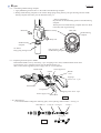
< 17 > Replacing electrical parts in handle
Disassemble handle cover by unscrewing 3 pcs. of tapping screws 4x25, and disassemble strain relief
by unscrewing 2 pcs. of tapping screws 4x18 as illustrated in Fig.14.
Then, switch, noise suppressor, power supply cord, etc. can be replaced.
Brush holder
Noise suppressor
Switch
Handle
cover
Tapping s
crew 4 x 25 : 3 pcs.
Brush holder
Cord guard
Tapping screw 4x18 : 2 pcs.
Power supply cord
Strain relief
Fig. 14
< 18 > Maintenance
It is recommended to change the following parts, when replacing carbon brushes. See Fig. 15.
Steel ball 7.0
O ring 12 O ring 15
O ring 16
Fig. 15
O ring 9
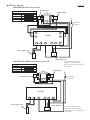
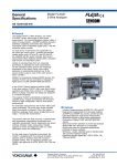
Circuit
P 14 / 16
diagram
Model HR2450 with reverse switch
Brush holder
Color index of lead wires
Black
White
Red
Blue
See-through
Brush holder
Connected
to field ore
3
2
Switch
4
1
2
M1
1
C1 C2
M2
Power supply cord
Noise suppressor
For some countries, noise
suppressor of two lead wire
type is used, or noise suppressor
is not used.
Model HR2451, HR2452 without reverse switch
Color index of lead wires
Black
Red
Blue
See-through
Brush holder
Brush holder
Connected
to field ore
Switch
1
Power supply cord
2
M1
C1 C2
M2
Noise suppressor
For some countries, noise
suppressor of two lead wire
type is used, or noise suppressor
is not used.
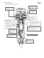
Wiring
P 15 / 16
diagram
Model HR2450 with reverse switch
Fix field lead wire (black)
with lead holder as per
the illustration.
Fix field lead wire (black)
with lead holder as per
the illustration.
Fix noise suppressor's
lead wire (see-through)
with lead holder
as per the illustration.
Fix brush holder's
lead wire (red) and
field lead wire (white)
with lead holder as per
the illustration.
* Pass brush holder's lead wire (red)
under the field lead wire (white).
* Do not slack brush holder's lead
wire (red) between brush holder and
lead holder.
Fix field brush holder's
lead wire (blue) and
field lead wire (black)
with lead holder as per
the illustration.
Fix lead wires which are passed
through this area, with any of
these lead holders.
Fix brush holder's
lead wire (blue) and
field lead wire (black)
with lead holder as per
the illustration.
* Pass brush holder's lead wire (blue)
under the field lead wire (black).
* Do not slack brush holder's lead
wire (blue) between brush holder and
lead holder.
Fix the following lead wires with this
lead holder.
* Brush holder's lead wire (red)
* 2 field's lead wires (black)
* Noise suppressor's lead wire (see-through)
Pass lead wires inside of the rib.
Noise suppressor
Noise suppressor is not
used in some countries
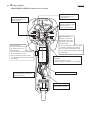
Wiring
P 16 / 16
diagram
Model HR2451, HR2452 without reverse switch
Fix field lead wire (black)
with lead holder as per
the illustration.
Fix brush holder's wire (red)
with lead holder as per
the illustration.
Fix noise suppressor's
lead wire (see-through)
with lead holder
as per the illustration.
Fix brush holder's
lead wire (red) and (blue)
with lead holder as per
the illustration.
* Pass brush holder's lead wire (red)
under the same of (blue).
* Do not slack brush holder's lead
wire (red) between brush holder and
lead holder.
Fix lead wires which are passed
through this area, with any of
these lead holders.
Fix brush holder's
lead wire (blue) and
field lead wire (black)
with lead holder as per
the illustration.
* Pass brush holder's lead wire (blue)
under the field lead wire (black).
* Do not slack brush holder's lead
wire (blue) between brush holder and
lead holder.
Fix the following lead wires with this
lead holder.
* 2 field's lead wires (black)
* Noise suppressor's lead wire (see-through)
Pass lead wires inside of the rib.
Noise suppressor
Noise suppressor is not
used in some countries