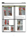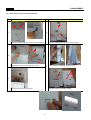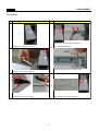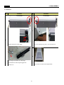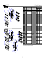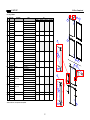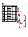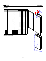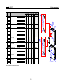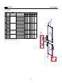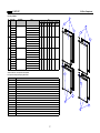
1
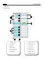
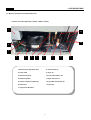
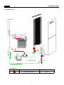
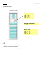
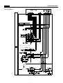
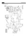
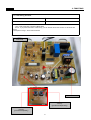
Service Manual
RN-271N
RN-272N
RN-273N
RN-274N
RN-331N
RN-332N
RN-333N
RN-334N
RN-335N
RN-336N
CONTENTS
1. SPECIFICATION
1-1. Model Information -------------------------------------------------------------------------------------------------------------------------------2
1-2. Interior Parts -----------------------------------------------------------------------------------------------------------------------------------------3
1-3. Machine Compartment View -----------------------------------------------------------------------------------------------------------------5
1-4. Refrigerant Cycle ----------------------------------------------------------------------------------------------------------------------------------6
1-5. Temperature Diagram ---------------------------------------------------------------------------------------------------------------------------7
1-6. Wire Diagram ----------------------------------------------------------------------------------------------------------------------------------------8
1-7. Main PCB Circuit Diagram --------------------------------------------------------------------------------------------------------------------9
2. FUNCTIONS
2-1. 'PCB VOLUME' Control -------------------------------------------------------------------------------------------------------------------------10
2-2. Temperature Control of Refrigerator compartment ---------------------------------------------------------------------------------11
2-3. Defrost Mode -----------------------------------------------------------------------------------------------------------------------------------------12
2-4. Function of Low Ambient Temperature -------------------------------------------------------------------------------------------------14
2-5. Time Saving Function ---------------------------------------------------------------------------------------------------------------------------15
2-6. Control of R Sensor OFF Point ---------------------------------------------------------------------------------------------------------------16
2-7. Error Display -------------------------------------------------------------------------------------------------------------------------------------------17
3. DISASSEMBLY
3-1. Door Switch --------------------------------------------------------------------------------------------------------------------------------------------18
3-2. Cover Multi-Flow Duct As (in Fresh food Compartment) --------------------------------------------------------------------------19
3-3. Louver F As (in Frozen Food Compartment) -------------------------------------------------------------------------------------------20
3-4. Door F/R -------------------------------------------------------------------------------------------------------------------------------------------------21
4. How to Change Door Position -----------------------------------------------------------------------------------------------------------------------23
5. How to Charge R-600a Refrigerant ---------------------------------------------------------------------------------------------------------------24
6. Part List
6-1. Cabinet/ Evavorator/ Compressor Compartment -------------------------------------------------------------------------------------29
6-2. Frozen Food Compartment --------------------------------------------------------------------------------------------------------------------30
6-3. Fresh Food Compartment -----------------------------------------------------------------------------------------------------------------------31
6-4. Door Compartment ---------------------------------------------------------------------------------------------------------------------------------32
1
1. SPECIFICATIONS
* is the Door Type
1-1. Model Information
Buyer No.
RN-27*N
RN-33*N
Factory No.
RFP-24*N….N
RFP-301*N….N
Control Type
Total
271
337
Freezer
110
111
Refrigerator
161
226
Total
240
305
Freezer
83
84
Refrigerator
157
221
Net Width (Packing)
545(584)
595(634)
Net Depth (Packing)
629(667)
650(685)
Net Height (Packing)
1800(1900)
1870(1970)
Gross Vol.
ISO 15502
(unit: L)
Storage Vol.
ISO 15502
(unit: L)
Diemension
(unit: mm)
KNOB & Digital Smart Control
Refrigerant Type
R-600a
Refrigerant Charge
0.044kg
Evaporator Type
Fin Type
Condenser Type
Natural Convection Cooling System
Dryer
Desiccant: Molecular Sieve xH-9
Capillary Tube (unit: mm)
ID0.7 x T0.55 x L2290
Defrost Type
Automatic Start & Stop
Defrost Heater
AC230V, 130W
Defrost Shape
Sheath Type
Freezer Fan Motor
AC 220V/50Hz, 2500RPM
Refrigerator Lighting
Bulb 15W x 1EA
Cooling Cycle
Heater
Electric Part
Net Weight (Packing)
63(68)kg
Blowing Agent
67(73)kg
C-Pentane
2
1. SPECIFICATIONS
1-2. Interior Parts
1-2-1. RN-271 model
2
7
1
3
5
4
6
8
10
10
9
10
11
12
13
1. Refrigerator Shelves
7. Refrigerator Pocket "R"
2. Lamp Window
8. Refrigerator Pocket "J"
3. Multi Duct
9. Freezer Shelves
4. Knob R Control
10. Freezer Case "A"
5. Cover Vegetable Case
11. Freezer Case "B"
6. Vegetable Case
12. Adjusting Leg (Left)
13. Adjusting Leg (Right)
3
1. SPECIFICATIONS
1-2. Interior Parts
1-2-2. RN-331 model
2
7
1
3
4
5
6
8
10
9
10
11
12
13
1. Refrigerator Shelves
7. Refrigerator Pocket "R"
2. Lamp Window
8. Refrigerator Pocket "J"
3. Multi Duct
9. Freezer Shelves
4. Knob R Control
10. Freezer Case "A"
5. Cover Vegetable Case
11. Freezer Case "B"
6. Vegetable Case
12. Adjusting Leg (Left)
13. Adjusting Leg (Right)
4
1. SPECIFICATIONS
1-3. Machine (Compressor) Compartment View
- Features are model dependent ( Below is RN-271 model )
1
13
12
2
3
4
5
6
7
8
9
10
1.Box Power As (Capacitor Run)
8. Suction Pipe As
2. Power Cord
9. Dryer As
3. Switch P Relay As
10. Case vaporization As
4. Earth Comp Wire
11.Pipe connector A
5. Fixture Compressor (Washer)
12. Pipe Wire Condensor As
6. Drain Hose
13. Pipe Hot
7. Compressor Absorber
5
11
1. SPECIFICATIONS
1-4. Refrigerant Cycle
Suction Pipe
⑦
Evaporator
⑥
⑧
Capillary Tube
③
②
④
①
Compressor
Pipe connector A
Dryer
⑤
- Welding Point
Copper Welding ( Ag 5%)
5 Point
Silver Welding ( Ag 30%)
3 Point
6
1. SPECIFICATIONS
1-5. Temperature Diagram
* Features are model dependent
( Below is RN-271 model )
Refrigerator Dial Mode
MIN: 5 ~ 8℃
MID: 2 ~ 5℃
MAX: -1 ~ 2℃
Vegetable compartment
: 1 ~ 5℃
Freezer Mode
LOW: -17 ~ -19℃
MID: -19 ~ -22℃
HIGH: -22 ~ -25℃
; The actual inner temperature varies depending on the food status, as the indicated setting temperature is a
target temperature, not actual temperature within refrigerator.
; Refrigeration function is weak in the initial time.
Please adjust temperature as above after using refrigerator for minimum 1 ~ 2 days.
7
1. SPECIFICATIONS
1-6. Wiring Diagram
8
1. SPECIFICATIONS
1.7. Main PCB Circuit Diagram
9
2. FUNCTIONS
2-1. "PCB VOLUME" Control
INPUT
CONTROL OBJECT
- Turn 'DIAL KNOB' on the 'COVER M/FLOW
DUCT'.
-PCB Volume
- Temperature is controlled by "PCB Volume" assembled with "Dial Knob".
- 12step(0step ~ 11step) mode of successive temperature mode
- Each model is diffrent using range.
RN_271 Model: step 0 ~ step 10
RN_331 Model: step 1 ~ step 11
- Features are model dependent ( Below is RN-271 model )
<'COVER M/FLOW DUCT AS': Air Duct Device in the Refrigerating Compartment>
R SENSOR
PCB VOLUME
DIAL KNOB
10
2. FUNCTIONS
2-2. Temperature Control of Refrigerator Compartment
INPUT
CONTROL OBJECT
- Turn 'DIAL KNOB'
- R sensor
- COMPRESSOR
- FAN
A. COMP and FAN will be controlled by the on/off condition of each mode.
B. Temperature Difference of Refrigerator each step :
STEP
0
1
2
3
4
5
6
7
8
9
10
11
ON(℃)
8.19
7.52
6.85
6.18
5.51
4.84
4.17
3.5
2.83
2.16
1.49
0.82
OFF(℃)
0.19
-0.48
-1.15
-1.82
-2.49
-3.16
-3.83
-4.5
-5.17
-5.84
-6.51
-7.18
Mid- 'Dial Knob': RN_271 Model
Mid-'Dial Knob': RN_331 Model
C. Temperature of Refrigerator at Mid-'Dial Knob' OFF point :
- RN_271 Model : -3.16℃,
- RN_331 Model: -3.83℃
D. Refrigerator ON/OFF Temp.
Difference: 8.0C
E. Temperature of Freezer Control
-It will be only controlled by using “KNOB F LOUVER” in the Freezer Comaprtment.
11
2. FUNCTIONS
2-3. Defrost Mode
INPUT
CONTROL OBJECT
- Accumulated Compressor Run Time
- Running Time Ratio of Compressor
- Accumulated Door Open Time
- Ambient temperature (RT)
- Compressor
- F Fan
- Defrost Heater
A. Defrost Mode Operation conditon
(1) In case accumulated compressor run times: 6, 8, 10, 12 hours,
- when there occur any errors:
R1, D1, C1, RT, Door SW error etc. (Check "2-9. ERROR DISPLAY")
- or, running rate of COMP (per 2hrs of accumulated operation time) is more than 90%
- or, accumulated door open time is over 2 minutes
- or, ambient temperature (RT) is more than 38℃
(2) Even if the above condition is not satisfied,
defrost mode starts immediately when accumulated compressor run time is 14hrs.
B. Normal Defrost Mode
• Comp ON, Fan On, Heater OFF
• Comp runs for 25min. before defrost mode
'PRE-COOL'
Defrost
Heater on
• Comp OFF, Fan OFF, Heater ON
• Heater off when 'D-Sensor' is over 10℃.
• Heater off after 60min. at normal control.
• Heater off after 40min. in case D1 error.
• Comp OFF, Fan OFF, Heater OFF
• 10minutes.
Pause
Normal
Operation
C. Forced Defrost Mode
- How to start:
(1) by press Door S/W for continuously and Control 'Dial Knob'(MIN -> MAX) 1 times.
(2) or, by press 'Test Key' 3 times on Main PCB
- If appliance has any error, Forces Defrost Mode don't start.
- Process: same as Normal Defrost Mode except 'PRE-COOL'
※ Heater is supposed to be on Initial 30sec. even though the temp. at “D SENSOR” is
over 13℃. (for TEST)
- How to confirm: If Force Defrost Mode start, you can buzzer sound
12
2. FUNCTIONS
2-3. Defrost Mode
D. Flow chart of How to Start Defrost Mode
※ A.C.R.T. : Accumulated Compessor Run Times
※ R.R.O.C. : Running Rate of Compressor
※ RT: Ambient temperature
Start
A.C.R.T.= 6,8,10,12hours
Yes
Yes
Any Error
No
Yes
R.R.O.C.(per 2hrs of A.C.R.T.)≥90%
No
Yes
Accumulated Door Open Time≥2min.
No
Yes
RT≥38℃
No
Yes
A.C.R.T.≥ 14hours
No
Defrost Mode Start
End
13
No
2. FUNCTIONS
2-4. Function of Low Ambient Temperature (RT)
INPUT
CONTROL OBJECT
RT
- R HTR
- COMP
A. Condition of LOW RT
- RT sensor below 19℃
- When the RT sensor is over 20℃, the system comes to be “General Operation Mode”.
- When the RT sensor is between 19°C to 20°C, the system keeps the previous mode.
B. Control
- When the temp of RT sensor is between 14°C to 19°C, COMP on/off temp is 3°C UP
- When the temp of RT sensor is below 14°C, COMP ON/OFF temp is 4°C UP
2-5. Prevention of Compressor Restart
INPUT
CONTROL OBJECT
N/A
COMP
It takes several minutes to protect Compressor:
(1) 6 minutes after Comp off
(2) 30 minutes at operation of Low RT, but 6 minutes when the doors open more than 20 seconds
2-6. Buzzer Sound
INPUT
CONTROL OBJECT
- Forced Defrost Mode start
- Door Switch
- Initial Power Input
Buzzer
A. When Forced Defrost Mode start, the buzzer rings 3times.
B. After 2 minutes power’s on, the buzzer rings 3 times.
C. At Short Circuit Test, the buzzer rings 1 times.
D. When door opens, the buzzer rings every 1 minute for 5 minutes.
14
2. FUNCTIONS
2-7. Time Saving Function
INPUT
CONTROL OBJECT
”FAST KEY”
Buzzer
A. How to Save
- 1 min : Click FAST KEY one time on MAIN PCB.
- 30 min : If you press FAST KEY continuously, you can reduce 30 minutes on each 2.5 seconds with
buzzer.
B. Example for usage: when reduce test time
MAIN PCB
LED
Test Key
(purchased separately)
Fast Key
(purchased separately)
15
2.FUNCTIONS
2-8. Control of R-sensor OFF Point
INPUT
CONTROL OBJECT
”J1” , “J2” On Main PCB
Control Resistance of R sensor OFF Point
- When the refrigeration of refrigerator is poor or weak though Fan and COMP are working continuously,
the following actions are recommended for service.
(1) Resistance (R25) : Default resistance (31.4Kohms)
(2) Resistance (R26) : Cut the “J1” off to reduce basic resistance by 1.5°C. (2Kohms up)
(3) Resistance (R27) : Cut the “J2” off additionally to reduce basic resistance by 1.5°C. (total 4Kohms up)
※ R25 = R-SENSOR OFF point
R25 + R26 = R-SENSOR OFF point - 1.5°C
R25 + R26 + R27 = R-SENSOR OFF point - 3°C
16
2. FUNCTIONS
2-9. Error Display
INPUT
CONTROL OBJECT
Sensor Error
LED Lamp
- ERROR DISPLAY
- If appliance has any errors, LED on the Main PCB is flickering.
- If the appliance is normal (no error), LED IS off.
A. 'R1' ERROR
: It happens when R-Sensor is OPEN or SHORT.
(1) LED DISPLAY: Shortly flickering(0.3sec.) 1 times.
(2) CONTROL:
Controlled by the following condition of RT
RT sensor TEMP
(unit:℃)
COMP. Operating ON/OFF TIME
(unit:min.)
~13
~19
~29
29~
6/34
10/30
16/24
20/20
※ If 'RT ERROR' happens at the same time, “COMP. ON/OFF Operating Time” is 16min/24min.
(3) RELEASE: When R-Sensor is working normally.
B. 'RT' ERROR
: It happens when RT-Sensor is OPEN or SHORT.
(1) LED DISPLAY: Shortly flickering(0.3sec.) 2 times.
(2) CONTROL: Delete the conditions of 'RT-sensor Control' and operate normally.
(3) RELEASE: When RT-Sensor is working normally.
flicker
C. 'd1' ERROR
: It happens when D-Sensor is OPEN or SHORT.
(1) LED DISPLAY: Shortly flickering(0.3sec.) 3 times.
(2) CONTROL: Return to next limit defrost time (40 min)
(3) RELEASE: When D-Sensor is working normally.
D. 'DR' ERROR
: It happens when the system senses door opens more than 1 hour.
(1) LED DISPLAY: Shortly flickering(0.3sec.) 4 times.
(2) CONTROL: Delete function relating to door switch sensing
(3) RELEASE: When sensing close from door S/W.
CODE
LED
ERROR
R1
1time
R sensor
RT
2times
RT sensor
d1
3times
D sensor
DR
4times
DR Switch
※ When pusing 'TEST KEY' on the main PCB,
LED is long(1.0sec.) flickering several times.
ex. 'Forced Defrost Mode:' long flickering 2 times
- To Confirm Errors:
Check LED on the main PCB
- The Priorities of Error :
R1→RT→D1→DR
17
3. DISASSEMBLY
3-1. Door Switch
No
Procedure
No
Procedure
1
Inuput a thin driver in the upper part as above picture.
And lift up 'Door Switch' carefully.
3
2
Inuput a thin driver in the lower part as above picture.
And lift up 'Door Switch' carefully.
Disconnect the wire housing.
18
3. DISASSEMBLY
3-2. Cover Multi-Flow Duct As (in Fresh food Compartment)
Procedure
No
No
Procedure
the Mark of Locking Position
1
Push
(2) Lever
Push
(1) Push
(2) Lever
4
Unlock the lamp window
Unlock the 'COVER M/FLOW DUCT'
(1) Push the window right side
(1) Check the marks of locking position on 'Cover'.
(2) Lever two window lock with flat driver
(Number of the marks are model dependent)
(2) Push the 'cover' inside and Unlock.
'A' axis
2
Open window turning on the axis 'A'
5
screw cap
unscrew
3
unscrew
Remove two screw cap with flat driver.
Unscrew 2 points
Disconnect the Lamp & Sensor wire housing.
19
3. DISASSEMBLY
3-3. Louver F As (in Frozen Food Compartment)
No
Procedure
Procedure
No
1
4
Unscrew to disassemble the 'Louver F As' from Freezer.
Unscrew to disassemble as each component part.
2
'A' axis
Remove the 'Louver F As' pulling the top side.
Unlock carefully. (especially, inside 3 locks)
5
inside 3
3
'KNOB F'
※Default position of 'KNOB F' is 'MID'
Disconnect Fan motor wire housing.
20
3. DISASSEMBLY
3-4. DOOR F/R
No
Procedure
No
Procedure
1
Remove door in fresh food compartment.
Tilt down the appliance to the rear.
And unscrew middle hinge.
4
washer
2
※ Don't forget the washer for middle hinge.
Lift up top cover hinge to remove.
3
5
Unscrew and remove top hinge.
Lift up middle cover hinge to remove.
21
3. DISASSEMBLY
3-4. DOOR F/R
Procedure
No
No
Procedure
7
6
Turn the 'Adjusting Leg (Left)' CCW and Remove.
Unscrew and remove under hinge.
washer
8
※ Don't forget the washer for under hinge.
※ The washer for under hinge's bigger than
middle one.
Remove door in frozen food compart ment.
22
4. How To Change Door Position
Features are model dependent ( Below is RN-271 model )
1-1> Tilt down the appliance to the rear.
(Watch out for "Pipe Wire Condensor" damage.)
a
1-2> Disassemble following parts in order.
b
- 'Top Cover Hinge' and 'Top Hinge'(a)
-'Refrigerator Door'(b)
d
- 'Middle Hinge'(c)
- 'Middle Cover Hinge'(d)
c
e
- 'Freezer Door'(e)
- 'Under Hinge'(f)
- 'Adjusting Leg '(g)
1-3> Move following 'Door Accessories' in the
opposite position:
- 'Cover Bushings'(i)
g
- 'Door Stoppers'(j)
f
1-4> Change the position of following parts each
other and assemble them:
i
'Adjusting Leg '(g) & 'Under Hinge'(f)
1-5> Level and assemble the 'Freezer Door'(e)
1-6> Change the position of following parts each
other and assemble them:
'Middle Cover Hinge'(d) & 'Middle Hinge'(c)
Refrigerator
Door
1-7>
Level and assemble the 'Refrigerator Door'(b).
Freezer
Door
1-8>
Assemble following parts on the opposite side:
j
'Top Cover Hinge' and 'Top Hinge'(a)
23
5. How To Charge R-600a Refrigerant
5-1. Safety Warning ( R-600a Refrigerant Models Only)
This appliance contains a certain amount of isobutane refrigerant (R600a) a natural gas with high
environmental compatibility that is, however, also combustible.
When transporting and installing the appliance, care should be taken to ensure that no parts of the
refrigerating circuit are damaged.
Refrigerant squirting out of the pipes could ignite or cause an eye injury. If a leak is detected, avoid
any naked flames or potential sources of ignition and air the room in which appliance is standing for
several minutes.
- In order to avoid the creation of a flammable gas-air mixture if a leak in the refrigerating circuit occurs, the size of the room
in which the appiance may be sited depends on the amount of refrigerant used. The room must be 1m3 in size for every 8g
of R600a refrigerant inside the appliance. The amount of refrigerant is shown on the identification plate inside the appliance.
- Never start up an appliance showing any sings of damage. If in doubt, consult your dealer.
5-2. Tools
24
5. How To Charge R-600a Refrigerant
5-3. Process Summary
1st Step.
R-600a ref.
discharging
2nd Step.
Removing
the remaning refrigerant
- Connect the discharging hose to
the outdoors.
- Time : 7 min.
4th Step.
Welding
coupling pipe
Coupling cap and
gas charging cap
should be
seperated before
welding.
3th Step.
Exchanging comp.
& dryer / pipe welding
- For removing of
remaning refrigerant.,
connect the discharging hose to
the vacuum pump
-Time : 10min
- Exchange Comp. and Dryer
- Welding the Pipe
- Copper-Copper : 5% rod
- Copper-Steel : 30% rod
6th Step.
Charge R-600a
5th Step.
Vacuum
- Check the vacuum
with (mani-polder)
gauge
- Charging the ref.
on POWER ON
- Time : 60~80min
- Time : 10min
5-4. In Detail Precess
NO.
SVC process
1
Connecting
the
pinch-plier
&
discharging
hose
Image
Details
1. Connect the discharging hose to
the pinch-plier
OUT DOOR
2. The outlet of discharging hose should
be placed to the outdoor(window)
1. Fix the pinch-plier to the compressor
2
charging pipe.
Fix ing
the pinch-plier
&
charging pipe
2. Pinch-plier should not be moving freely.
※ If that is moving freely, it would cause
fire/explosion as leakage gas in the room.
1. Discharge the R-600a ref. to outdoor.
[Befor connecting the vacuum pump]
3
Discharging
the R-600a ref.
※ It should have enough time more than
7 minutes to discharge.
1. And then, connect the vacuum pump
25
4
Remov ing the
to the outlet of discharging hose
※Vacum pump should be placed at
fire/explosion as leakage gas in the room.
1. Discharge the R-600a ref. to outdoor.
[Befor connecting the vacuum pump]
3
Discharging
the R-600a ref.
5. How To Charge R-600a Refrigerant
※ It should have enough time more than
NO.
SVC process
14
Connecting
the
pinch-plier
Remov
ing the
& ref.
remaining
discharging
hose
Image
Details
7 minutes to discharge.
1. Connect
discharging
hose to
And then,the
connect
the vacuum
pump
the
pinch-plier
to the
outlet of discharging hose
OUT DOOR
※Vacum
pumpofshould
be placed
at should
2.
The outlet
discharging
hose
the outdoor where is able to clear air easily.
be placed to the outdoor(window)
※ It should have enough time
more than 10 minutes to discharge.
1.
the pinch-plier
to thepipe
compressor
1. Fix
Disassembe
the each
(Del-pipe,
25
Fix ing
the
pinch-plier
Remov ing the
& & pipe
pinch-plier
charging pipe
NO.
SVC process
charging
Suc-pipe,pipe.
Capi-pipe, Dryer & Hot-pipe)
2. Pinch-plier should not be moving freely.
※ Caution ; A part is easily damaged
※ by
If that
is moving
it would
cause
flame
so that freely,
disassemly
should
be done carefully.
fire/explosion
as Details
leakage gas in the room.
Image
1. Change
Discharge
R-600a
ref. to outdoor.
1.
thethe
comp.
& dryer.
[Befor connecting the vacuum pump]
36
Discharging
Ex changing
comp
the R-600a
& dry erref.
※ You should check the comp. spec.
※ and
It should
have enough
time more than
assemble
correctly.
7 minutes to discharge.
1. And
connect
the vacuum pump
Weldthen,
the each
pipe.
to the outlet of discharging hose
4
7
Remov ing the
remaining ref.
※Vacum pump should be placed at
the outdoor where is able to clear air easily.
※ It should have enough time
※
O Copper-Copper
welding
- 5% rod
more
than 10 minutes to
discharge.
W elding
1. Disassembe
the each
pipe- (Del-pipe,
△ Copper-Steel
welding
35% rod
Suc-pipe, Capi-pipe, Dryer & Hot-pipe)
5
8
Remov ing the
pinch-plier & pipe
Disassembly
of charging v alv e
(Coupling pipe)
※ Caution ; A part is easily damaged
by flame so that disassemly should
be done carefully.
Valve Ass'y
1. Decap the couplig pipe cap and
Valve Ass'y
disassemble the vlave ass'y.
※ If you don't disassemble, the coupling
rubber would be melted.
1. Weld after inserting the coupling pipe
to the compressor.
9
Coupling pipe
welding
26
※ Use the wet cloth for preventing the
other part of machinery-room from damage.
8
Disassembly
of charging v alv e
(Coupling pipe)
NO.
SVC process
1
9
Connecting
the
pinch-plier
Coupling
pipe
&
welding
discharging
hose
SVC process
NO.
Valve Ass'y
1. Decap the couplig pipe cap and
Valve Ass'y
disassemble the vlave ass'y.
5. How To Charge R-600a Refrigerant
※ If you don't disassemble, the coupling
Image
rubber would beDetails
melted.
Connect
the
discharging
hose to pipe
1. Weld
after
inserting
the coupling
the
pinch-plier
to the
compressor.
OUT DOOR
2. The outlet of discharging hose should
placed
to the
outdoor(window)
※beUse
the wet
cloth
for preventing the
Image
Details
other part of machinery-room
from damage.
1. Reassemble
the valve
with
Fix the pinch-plier
to theass'y
compressor
2
10
coupling pipe.
pipe to clockwise.
charging
Fix ing
the pinch-plier
&
charging pipe
2.Pinch-plier
Connect the
blue hose
the guage
2.
should
not beofmoving
freely.
the coupling
anditthe
yellow
hose
※to
If that
is movingpipe
freely,
would
cause
Valv e reass' y
&
guage connecting
to the vacuumaspump.
fire/explosion
leakage gas in the room.
3.
the blue
lever
1.Open
Discharge
theguage
R-600a
ref. to outdoor.
and start
the vacuum
pump pump]
[Befor
connecting
the vacuum
3
Discharging
the R-600a ref.
※ It should have enough time more than
7 minutes to discharge.
1.And
Be vacuumed
the the
cycle
with pump.
1.
then, connect
vacuum
pump
to the outlet of discharging hose
11
4
Remov
ing the
Vacuum
remaining ref.
※Vacum
should be placed at
※ Timepump
: 60~80min
the outdoor where is able to clear air easily.
=> If the vacuum time is less than 60min,
※ It should have enough time
ref. COP & air coolong would be weak.
more than 10 minutes to discharge.
1.
Check the guage
: -76㎝Hg
1. Disassembe
the each
pipe (Del-pipe,
Suc-pipe, Capi-pipe, Dryer & Hot-pipe)
12
5
Remov
ing the
Check
pinch-plier & pipe
※ Caution ; A part is easily damaged
※by
If the
cycle
notdisassemly
vacuumed,should
flame
so is
that
be
done carefully.
it would
be leak.
1. Check the amounts of R-600a can
with scale and discharge the surplus ref.
13
※ Discharging is surely done at the outdoor
where is able to clear air.
Adjusting
the amounts of
refrigerants
(R-600a can)
※ Tip of adjusting.
- Can total weight :160g(Can 75g+Ref. 85g)
- Adapter : 145g
=> Total : 305g
- The amounts of charging : 79g
=> Discharging : 6g => Total : 299g
27
5. How To Charge R-600a Refrigerant
NO.
SVC process
Image
Details
1. Conect can adapter to the coupling pipe.
14
2. Charge the ref. with open lever slowly.
Connecting of
coupling pipe
&
adapta
※ Refrigerant should never leak in the room.
1. On the power of refrigerator and then
start to charge the ref. (10min)
15
Charging
※ Charge the ref. until going out the water
vapour condensing on the can outlet.
1. Check the leakage.
16
Leakage Test
※ You must rework from Step.1
when the leakage is detected.
1. Clean and clear around the machinery
room when the service is finished.
17
Finish
2. Assemble the machinery room cover.
28
6-1. Cabinet / Evaporator / Compressor Compartment
6. PART LIST
NO
A19-1
A4
A3
A1
A28-2
A23
A22
A19
A18
A24
A20
A25
A26
A5
A6
A16
A29 A30
301149CB00 COVER M/PCB BOX AS
SECC (WHITE)
1
1
301149CB10
SECC (GRAY)
301149CB20
SECC (BLACK)
A3
A4
3012937900 HINGE *T AS
3001448500 COVER HI *T
RFP-301
PP (WHITE)
1
1
1
1
A5
3001448510
3001448520
301179DP00 DOOR S/W AS
PP (GRAY)
PP (BLACK)
HC-050K4 250V2.5A
1
1
A6
3010937720 CAP DV HI HOLE *M
HIPS
1
1
A7
A8
3012938000 HINGE *M AS
3016044410 SPECIAL WASHER *M HI
RFP-301
SGCC, T1.0 x I.D9.0 x O.D15
1
1
1
1
A9
3012106500 FOOT ADJ *L AS
PP+INSERT
1
1
A10
A10-1
3012938100 HINGE *U AS
RFP-301
1
1
3012105300
3816000200
3017069800
3012831100
3012764100
3017070000
3012831200
3010365200
3010365500
FOOT ADJ AS
SPECIAL WASHER
EVA AS
HEATER SHEATH AS
HARNESS D SENS
EVA AS
HEATER SHEATH AS
BASE COMP AS
PP+INSERT
SPCC T1.0 x O.D21 x I.D8 MFZN
RFP-241(230V 130W)
RFP-241(230V 130W)
RFP-340(NBC-K43-24)
RFP-301(230V 130W)
RFP-301(230V 130W)
RFP-241
RFP-301
1
1
1
1
1
0
0
1
0
1
1
0
0
1
1
1
0
1
301119VJ00
3014479400
3012513950
3014480010
3014480000
3012041500
3016808200
3010103400
3956188C50
4019H09031
3015103900
CASE VAPORI AS
PIPE CONN A
HOSE DRN B
PIPE WI-CON AS
PIPE WI-CON SAS
FIXTURE W-ICON
DRYER AS
ABSORBER COMP
COMPRESSOR
SPECIAL WASHER
RFP-301
DUCT1-0 OD4.76*T0.5
PVC
RFP-301
RFP-301
HIPS
10G, SINGLE TUBE
RUBBER
LZ88CY(QLZ12Y) 220-240V 50HZ
SWRH
LZ88CY OLP FIXING
B60-120, QP2-15C(RSCR DONPER)
1
1
1
1
1
4
1
4
1
2
1
1
1
1
1
1
4
1
4
1
2
1
BS-1363A,M-240(N),250V/13A,BLACK
1
1
1
1
1
1
1
1
1
1
1
1
1
1
FR-290, 250V 10/16A
FRM-241, L140
1
1
A20
A21
A22
A23
A24
A14
A12-2
A12-1
A25
A26
A27
A28
A28-1
A28-2
A15
A12-2
A9
A12
A10
1
A2
A16
A17
A18
A19
A19-1
A19-2
A21
A17
A7
A13-1
A11
A29
A30
A10-1
3018134600
3811402600
3015103800
3010583700
3010552101
3016406010
3011349001
3011348111
3012763210
SPRING OVERLOAD PROTECTOR
SWITCH P RELAY AS
COVER RELAY
SPRING COVER RELAY
BOX POWER AS
BOX POWER
CAPACITOR RUN
CORD POWER AS
*dependent on the contry
HARNESS EARTH COMP
LZ88CY
LZ88CY COVER RELAY FIXING
RFP-301(400V/4UF)
GI/T0.5
DMF-40405(400V 4UF)
* Please check the color, some parts code color dependent.
A13
29
RN_33*
1
A14
A15
A27
A8
Q'ty
RN_27*
RFP-301
A13
A13-1
A28
SPEC.
30143KW060 PCB MAIN AS
A11
A12
A12-1
A12-2
A28-1
PART NAME
A1
A19-2
A2
PART-CODE
6-2. Frozen Food Compartment
6. PART LIST
RN_27*
NO
B4
B1
B1
B4-4
B3
B1
B5
B4-2
B4-3
B6
B4-4
B7
30
0
GPPS(CRYSTAL)
301119UY10
301119UY20
GPPS(GRAY)
GPPS(BLUE)
B3
B4
B4-1
3017861400 SHELF GLAS F
3018932200 LOUVER F AS
3015922200 MOTOR F AS
GLASS T3.2 RFP-241
RFP-241(AC 230V 50HZ)
AC220V/50HZ,2500RPM
3
1
1
0
0
1
B4-2
3010664700 BRACKET FAN MOTR
PP, T2.0 (AC)
1
1
B4-3
B4-4
3011835900 FAN
3013415800 KNOB F CONTL
OD100,SHAFT OD3.17
PP
1
1
1
1
B5
3010564910 CASE ICEING AS
CASE ICEING+VINYL
1
1
B6
301119V100 CASE F A
GPPS(CRYSTAL)
0
2
301119V110
301119V120
301119V200 CASE F B
301119V210
301119V220
3017861500 SHELF GLAS F
3018932500 LOUVER F AS
GPPS(GRAY)
GPPS(BLUE)
GPPS(CRYSTAL)
GPPS(GRAY)
GPPS(BLUE)
GLASS T3.2 RFP-301
RFP-301(AC 230V 50HZ)
0
1
0
0
2
1
* Please check the color, some parts code color dependent.
B4-1
1
GPPS(BLUE)
301119UY00 CASE F B
B8
B9
B9
0
301119UX20
B7
RN_33*
RN_33*
3
GPPS(GRAY)
B3
B2
Q'ty
RN_27*
301119UX10
B2
B4-2
B1
B8
SPEC.
GPPS(CRYSTAL)
B3
B8
PART NAME
301119UX00 CASE F A
B5
B4-3
B6
PART-CODE
B4-1
6-3. Fresh Food Compartment
6. PART LIST
RN_27*
NO
C5
C1
C5-3
C5-5
C2
C14
C13
C3
C5-1
RFP-241
2
0
0
T3.2
1
0
0
C3
301119UW00 CASE VEGTB
GPPS(CRYSTAL)
1
0
0
301119UW10
301119UW20
GPPS(GRAY)
GPPS(BLUE)
C4
C5
C5-1
3015523800 WINDOW M/FLOW DUCT
GPPS
3001448400 COVER M/FLOW DUCT AS RFP-241
3013415700 KNOB R CONTL
HIPS + PRINT
1
1
1
1
0
1
0
0
0
C5-2
3017903900 SOCKET LAMP AS
1
1
1
C5-3
C5-4
3013600020 LAMP AS
15W (E14,CC7A)
3012783300 HARNESS PCB VOLUME AS R SENSOR' + 'Wire lead'
1
1
1
1
1
1
C5-5
30143KW260 PCB VOLUME AS
BALLISTA VOLUME
1
1
1
C6
3017861100 SHELF R AS
RFP-241
0
3
3
C7
C8
301119V400
301119V000
301119V010
301119V020
301149C400
301149CE00
3013415900
3015523900
3019068500
0
0
1
1
1
1
0
0
0
0
2
1
0
0
0
0
0
1
1
1
0
1
0
0
1
0
1
3
1
3
0
1
1
0
1(OPTION)
1(OPTION)
C11
C12
C5-3
C13
C15
C5-4
C14
C15
C6
C14
C5-5
C16
C5-2
C16
C7
C5-1
C5-3
C10
C17
C8
C11
3019068510
3019068520
3019068600
3019068610
3019068620
3011190800
3019068700
3019068710
3019068720
3019068800
3019068810
CASE GLAS VEGTB
CASE VEGTB
T3.2
GPPS(CRYSTAL)
GPPS(GRAY)
GPPS(BLUE)
COVER M/FLOW DUCT AS RFP-301
COVER M/FLOW DUCT AS RFP-30F
KNOB R CONTL
HIPS, RFP-30F
WINDOW M/FLOW DUCT
GPPS
POCKET R
GPPS(CRYSTAL)
POCKET J
CASE EGG TRAY
POCKET R
POCKET J
3019068820
3017861900 SHELF WINE
GPPS(GRAY)
GPPS(BLUE)
GPPS(CRYSTAL)
GPPS(GRAY)
GPPS(BLUE)
GPPS(CRYSTAL)
GPPS(CRYSTAL)
GPPS(GRAY)
GPPS(BLUE)
GPPS(CRYSTAL)
GPPS(GRAY)
GPPS(BLUE)
SUS 204
* Please check the color, some parts code color dependent.
C5-4
C5-5
C10-1
31
RN_33
NEW
3017860900 SHELF R AS
C10-1
C4
RN_331/ 2/
3/ 4/ 5/ 6
301119UZ00 CASE GLAS VEGTB
C9
C10
C5-2
Q'ty
RN_
27*
C2
C12
C17
SPEC.
C1
C5-4
C9
PART NAME
C5-2
C4
RN_33*
PART-CODE
6-4. Door Compartment
6. PART LIST
6-4-1. RN_27* Models
NO
D1
PART-CODE
PART NAME
SPEC.
D1
Q'ty
RN_271
RN_272
RN_273
RN_274
1
0
0
0
30100B9M00 ASSY R DR
WHITE(DWG1C)
30100B9M30
AL SILVER(ASG4P)
30100B9M40
30100B9M50
TITANIUM SILVER(TSH1P)
BLACK(BLH1C)
D1-1
30100B9M60
3012330800 GASKET F R DR AS
3012330710
PLATINUM SILVER(PSH1P)
RFP-241(GRAY)
RFP-241(BLACK)
2
2
2
2
D1-2
3011450300 COVER CAP HOLE A
ABS(WHITE)
2
2
2
2
3011450310
3011450340
ABS(SILVER)
ABS(BLACK)
30100B9L00 ASSY F DR
WHITE(DWG1C)
1
0
0
0
30100B9L30
AL SILVER(ASG4P)
30100B9L40
30100B9L50
30100B9L60
30100B9M20 ASSY R DR
30100B9MB0
30100B9MC0
30100B9MD0
30100B9ME0
301099BV00 CAP DR
TITANIUM SILVER(TSH1P)
BLACK(BLH1C)
PLATINUM SILVER(PSH1P)
WHITE(DWG1C)
AL SILVER(ASG4P)
TITANIUM SILVER(TSH1P)
BLACK(BLH1C)
PLATINUM SILVER(PSH1P)
ABS(WHITE)
0
1
1
0
301099BV10
301099BV20
30100B9L20 ASSY F DR
30100B9M70
30100B9M80
30100B9M90
30100B9MA0
3014011300 PACKING HNDL AS
3014011310 (*AL BAR TYPE)
3014011320
3014011330
3012659700 HANDLE BAR AS
3012659710 (*AL BAR TYPE)
ABS(SILVER)
ABS(BLACK)
WHITE(DWG1C)
AL SILVER(ASG4P)
TITANIUM SILVER(TSH1P)
BLACK(BLH1C)
PLATINUM SILVER(PSH1P)
DECO(WHITE)+BAR(NATURAL)
DECO(BLACK)+BAR(BLACK)
DECO(SILVER)+BAR(NATURAL)
DECO(TITANIUM)+BAR(TITANIUM)
D2
D3
D3-1
D4
D5
D5-1
D5-2
D5-3
3012659720
3012659730
3016040500 SPECIAL GRIP HNDL
3010985200 CAP HNDL
3010985210
3010985220
AL(HAIR LINE+NATURAL COLOR)
AL(HAIR LINE+BLACK)
AL(HAIR LINE+NATURAL COLOR)
AL(HAIR LINE+TITANIUM SILVER)
M5XL16 MFZN
ABS (WHITE)
ABS (SILVER)
ABS (BLACK)
D1-1
D1-2
D1-2
D5
D5-3
D5-2
D2
0
4
4
4
0
1
1
0
D3
D1-1
D3-1
D5-1
D6
0
1
0
0
0
2
0
0
D5-3
D5-2
0
0
4
4
4
4
* Please check the color, some parts code color dependent.
4
4
D6-1
32
D4
6-4. Door Compartment
6. PART LIST
6-4-1. RN_27* Models
NO
PART-CODE
PART NAME
SPEC.
3014011400 PACKING HNDL AS
3014011410 (*ABS BAR TYPE)
WHITE
3014011420
3014011430
SILVER
TITANIUM SILVER
D6-1
3012659800 HANDLE BAR AS
3012659810 (*ABS BAR TYPE)
3012659820
WHITE
BLACK
SILVER
3012659830
TITANIUM SILVER
D7
30100B9M10 ASSY R DR
30100B9MF0
WHITE(DWG1C)
AL SILVER(ASG4P)
30100B9MG0
TITANIUM SILVER(TSH1P)
30100B9MH0
BLACK(BLH1C)
30100B9MJ0
30100B9L10 ASSY F DR
30100B9L70
30100B9L80
30100B9L90
30100B9LA0
3014011100 PACKING HNDL AS
3014011110 (*GAS INJECTION TYPE)
3014011120
3012659300 HANDLE
3012659310 (*GAS INJECTION TYPE)
PLATINUM SILVER(PSH1P)
WHITE(DWG1C)
AL SILVER(ASG4P)
TITANIUM SILVER(TSH1P)
BLACK(BLH1C)
PLATINUM SILVER(PSH1P)
RFP-304, WHITE
RFP-304, SILVER
RFP-304, BLACK
D6
D8
D9
D9-1
3012659320
Q'ty
RN_271
RN_272
RN_273
RN_274
0
0
1
0
D9
BLACK
ABS, WHITE
ABS, SILVER
ABS, BLACK
D5-3
0
0
2
0
0
0
0
1
D5-2
D7
D9-1
D1-2
0
0
0
1
0
0
0
1
0
0
0
2
D1-1
D3-1
* Please check the color, some parts code color dependent.
D1-2
D1-1
D8
33
6-4. Door Compartment
6. PART LIST
6-4-2. RN_33* Models
NO
E1
PART-CODE
PART NAME
SPEC.
Q'ty
RN_
331
RN_
332
RN_
333
RN_
334
RN_
335
RN_
336
Hidden
Hinge
1
0
0
0
0
0
0
1
1
1
1
1
1
1
2
2
2
2
2
2
1
30100B9Y00 ASSY R DR
WHITE(DWG1C)
30100B9Y40
30100B9Y50
AL SILVER(ASG4P)
TITANIUM SILVER(TSH1P)
30100B9Y60
30100B9Y70
3012331000 GASKET R DR AS
BLACK(BLH1C)
PLATINUM SILVER(PSH1P)
RFP-241(GRAY)
3012331010
RFP-241(BLACK)
E1-2
3011450300 COVER CAP HOLE A
3011450310
ABS(WHITE)
ABS(SILVER)
3011450340
ABS(BLACK)
E2
30100B9X00 ASSY F DR
WHITE(DWG1C)
1
0
0
0
0
0
1
E2-1
30100B9X30
30100B9X40
30100B9X50
30100B9X60
3012330900 GASKET F R DR AS
3012330910
ASSY R DR
-
AL SILVER(ASG4P)
TITANIUM SILVER(TSH1P)
BLACK(BLH1C)
PLATINUM SILVER(PSH1P)
RFP-241(GRAY)
RFP-241(BLACK)
WHITE(DWG1C)
AL SILVER(ASG4P)
TITANIUM SILVER(TSH1P)
1
1
1
1
1
1
1
0
0
0
0
0
0
1
E1-1
E**
-
E1
E1-1
E**
E1-2
BLACK(BLH1C)
PLATINUM SILVER(PSH1P)
E1-2
* Please check the color, some parts code color dependent.
E2
E2-1
34
6-4. Door Compartment
6. PART LIST
6-4-2. RN_33* Models
NO
E3
E3-1
E4
E5
E5-1
E5-2
E5-3
E6
E6-1
PART-CODE
PART NAME
SPEC.
30100B9Y20 ASSY R DR
WHITE(DWG1C)
30100B9YL0
30100B9YC0
WHITE(DWH1L)
AL SILVER(ASG4P)
30100B9YD0
30100B9YE0
30100B9YF0
TITANIUM SILVER(TSH1P)
BLACK(BLH1C)
PLATINUM SILVER(PSH1P)
301099BV00 CAP DR
ABS(WHITE)
301099BV10
301099BV20
ABS(SILVER)
ABS(BLACK)
30100B9X20 ASSY F DR
WHITE(DWG1C)
30100B9XB0
WHITE(DWH1L)
30100B9Y80
30100B9Y90
30100B9YA0
30100B9YB0
3014011300 PACKING HNDL AS
3014011310 (*AL BAR TYPE)
3014011320
3014011330
3012659700 HANDLE BAR AS
3012659710 (*AL BAR TYPE)
AL SILVER(ASG4P)
TITANIUM SILVER(TSH1P)
BLACK(BLH1C)
PLATINUM SILVER(PSH1P)
DECO(WHITE)+BAR(NATURAL)
DECO(BLACK)+BAR(BLACK)
DECO(SILVER)+BAR(NATURAL)
DECO(TITANIUM)+BAR(TITANIUM)
3012659720
3012659730
3016040500
3010985200
3010985210
3010985220
3014011400
3014011410
3014011420
3014011430
SPECIAL GRIP HNDL
CAP HNDL
PACKING HNDL AS
(*ABS BAR TYPE)
3012659800 HANDLE BAR AS
3012659810 (*ABS BAR TYPE)
3012659820
3012659830
AL(HAIR LINE+NATURAL COLOR)
AL(HAIR LINE+BLACK)
AL(HAIR LINE+NATURAL COLOR)
AL(HAIR LINE+TITANIUM SILVER)
M5XL16 MFZN
ABS (WHITE)
ABS (SILVER)
ABS (BLACK)
WHITE
BLACK
SILVER
TITANIUM SILVER
WHITE
BLACK
SILVER
TITANIUM SILVER
Q'ty
RN_
331
RN_
332
RN_
333
RN_
334
RN_
335
RN_
336
Hidden
Hinge
0
1
1
0
0
0
0
E5
E5-3
E5-2
0
4
4
4
0
0
E3
E1-2
0
E1-1
0
1
1
0
0
0
0
E5-1
0
1
0
0
0
0
1(OPTION)
E3-1
E6
0
2
0
0
0
0
2(OPTION)
E5-3
E5-2
0
0
4
4
4
4
4
4
0
0
0
0
4(OPTION)
4(OPTION)
E1-2
0
0
1
0
0
0
1(OPTION)
0
0
2
0
0
0
2(OPTION)
E3-1
E6-1
E2-1
E4
* Please check the color, some parts code color dependent.
35
6-4. Door Compartment
6. PART LIST
6-4-2. RN_33* Models
NO
E7
E8
E9
E9-1
PART-CODE
PART NAME
SPEC.
30100B9Y10 ASSY R DR
WHITE(DWG1C)
30100B9YG0
30100B9YH0
AL SILVER(ASG4P)
TITANIUM SILVER(TSH1P)
30100B9YJ0
30100B9YK0
30100B9X10 ASSY F DR
BLACK(BLH1C)
PLATINUM SILVER(PSH1P)
WHITE(DWG1C)
30100B9X70
AL SILVER(ASG4P)
30100B9X80
30100B9X90
TITANIUM SILVER(TSH1P)
BLACK(BLH1C)
30100B9XA0
PLATINUM SILVER(PSH1P)
3014011100 PACKING HNDL AS
3014011110 (*GAS INJECTION TYPE)
3014011120
3012659300 HANDLE
3012659310 (*GAS INJECTION TYPE)
3012659320
Q'ty
RN_
331
RN_
332
RN_
333
RN_
334
RN_
335
RN_
336
Hidden
Hinge
0
0
0
1
0
0
0
E7
E1-2
0
0
0
1
0
0
0
RFP-304, WHITE
0
0
0
1
0
0
1(OPTION)
RFP-304, SILVER
RFP-304, BLACK
ABS, WHITE
ABS, SILVER
ABS, BLACK
0
0
0
2
0
0
2(OPTION)
E9
E3-1
E5-3
* Please check the color, some parts code color dependent.
E5-2
E9-1
E1-2
E3-1
E8
36
6-4. Door Compartment
6. PART LIST
6-4-2. RN_33* Models
E12
NO
E10
E11
PART-CODE
PART NAME
SPEC.
30000CPM00 ASSY R DR
WHITE(DWG1C)
30000CPM10
30000CPM20
AL SILVER(ASG4P)
TITANIUM SILVER(TSH1P)
30000CPM30
30000CPM40
30000CPN00 ASSY F DR
BLACK(BLH1C)
PLATINUM SILVER(PSH1P)
WHITE(DWG1C)
30000CPN10
AL SILVER(ASG4P)
30000CPN20
30000CPN30
TITANIUM SILVER(TSH1P)
BLACK(BLH1C)
Q'ty
RN_
331
RN_
332
RN_
333
RN_
334
RN_
335
RN_
336
Hidden
Hinge
0
0
0
0
1
0
0
E10
E1-1
E1-2
0
0
0
0
1
0
0
E1-1
30000CPN40
PLATINUM SILVER(PSH1P)
E12
30000CPP00 ASSY R DR
WHITE(DWG1C)
0
0
0
0
0
1
0
E13
30000CPP10
30000CPP20
30000CPP30
30000CPP40
30000CPQ00 ASSY F DR
30000CPQ10
30000CPQ20
30000CPQ30
30000CPQ40
AL SILVER(ASG4P)
TITANIUM SILVER(TSH1P)
BLACK(BLH1C)
PLATINUM SILVER(PSH1P)
WHITE(DWG1C)
AL SILVER(ASG4P)
TITANIUM SILVER(TSH1P)
BLACK(BLH1C)
PLATINUM SILVER(PSH1P)
0
0
0
0
0
1
0
* Please check the color, some parts code color dependent.
*Some parts can be changed for improving without notice.
Date
E1-2
E1-2
Note
E1-2
E2-1
E13
E2-1
E11
37