1
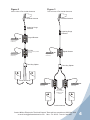
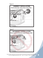
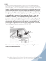
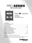
In-Line or 75 Ohm In-Line
17dB Adjustable Gain
800/1900 MHz
Smart Technology
Signal Booster
™
Contents:
Quick Install Overview. . . . . . . . . . . . . . . . . . . . . . . . . . . . . .
Installation Diagram. . . . . . . . . . . . . . . . . . . . . . . . . . . . . . . .
Understanding the Signal Booster Lights . . . . . . . . . . . . . . .
Warnings and Recommendations. . . . . . . . . . . . . . . . . . . . .
2
3
9
11
Appearance of device and accessories may vary.
Note: This manual contains important safety and operating information. Please read and
follow the instructions in this manual. Failure to do so could be hazardous and result in
damage to your Signal Booster.
Installation Instructions for:
In-Line or 75 Ohm In-Line
17dB Adjustable Gain 800/1900 MHz Smart Technology ™ Signal Booster
Model # 276215 FCC ID: PWO276215 IC: 4726A-276215
The term “IC” before the radio certification number only signifies that Industry Canada technical
specifications were met.
How it Works
The In-Line Signal Booster is designed to provide an additional 17dB gain to
compensate for signal loss due to a long cable run or the use of taps or splitters.
The In-Line Signal Booster allows installation of multiple inside antennas with
minimal signal loss and is installed between a Wilson indoor Signal Booster, like
the AG Pro Installer, and the Inside Antenna. Optimally, the In-Line Signal Booster
is installed after long runs of cable and/or taps and splitters to compensate for the
signal loss. The In-Line Signal Booster can be installed in the middle of a cable
run or near the inside antenna.
The In-Line is designed to offset cable and splitter/tap loss for In-Building
installations. It should be used on the Inside Antenna side of a Wilson Electronics
In-Building Signal Booster such as the AG Pro 75™.
Inside this Package
Note: Kits may contain different accessories
In-Line
(806215 & 806715)
Indoor Antenna Options
50 ohms
301135
304451
304452
304453
75 ohms
301155
304471
304472
304473
AC/DC Power Supply
6V / 2.5A
(859912)
Tap Option
Note: Splitter Options on page 3.
50 ohm
(859907)
Appearance of device and accessories may vary.
To purchase, call Wilson Electronics Sales Department at: 800-204-4104
1
Contact Wilson Electronics Technical Support Team with any questions at 866-294-1660
or email: [email protected]. Mon.- Fri. Hours: 7 am to 6 pm MST.
Quick Install Overview
Refer to Installation Diagrams on page 3 & 4. Contact Wilson Electronics Technical
Support Team with any questions at 866-294-1660.
1. Install In-Building Signal Booster (such as the AG Pro 75™ sold separately). Use the installation guide for the model you purchased to install.
2. Select a location to install the In-Line that is away from excessive heat, direct sunlight, moisture and has proper ventilation. Do not place the In-Line in an air-tight enclosure.
3. The In-Line should be placed where it can make up for installation gain loss due to cable, taps or splitters. Optimal location is near or directly connected to the Inside Antenna.
4. a) Connect a cable to the In-Building Signal Booster at the connector labeled “Inside Antenna.”
b) Run the cable to the In-Line, attach to the connector labeled “Outside Antenna.”
c) From the In-Line connector marked “Inside Antenna” run a cable to the Inside Antenna. For more information on running cable (refer to diagrams on pages 3 & 4).
5. Before powering up the In-Line, verify that all cables are connected and check that all connections are tight.
Note: Be careful when plugging the connectors in so as not to bend the center pins on the connectors.
6. The In-Line has been packaged with the gain control knobs adjusted to the highest gain position. If one or both of the lights are not green (refer to pages 9 & 10).
Warning: Connecting the Signal Booster directly to a cell phone with use of an adapter may damage the cell phone and/or the Signal Booster.
Contact Wilson Electronics Technical Support Team with any questions at 866-294-1660
or email: [email protected]. Mon.- Fri. Hours: 7 am to 6 pm MST.
2
Before Getting Started
This guide will help you properly install your Wilson Electronics Signal Booster. It
is important to read through all of the installation steps for your particular
application prior to installing any equipment. Read through the instructions,
visualize where all the equipment will need to be installed and do a soft
installation before mounting any equipment. Contact Wilson Electronics Technical
Support with any questions at: 866-294-1660.
Installation Diagrams
Note: Do not install the In-Line without
an In-Building Signal Booster between
the Outside Antenna and In-Line.
Figure 1
One In-Line & One Inside Antenna
Note: Install the In-Line as close as
possible to Inside Antenna for optimal performance.
Outside Antenna
Lightning Surge
Protector
Splitter Options
800
800
1900
SMART
TECHNOLOGY
62
37
2-Way (859957)
50 ohm
3-Way (859980)
50 ohm
32
42
47
37
62
Signal Booster
Signal Booster
32
42
1900
MHz
52
57
1900
SMART
TECHNOLOGY
Signal Booster
32
800
MHz
47
52
57
4-Way (859981)
50 ohm
Surge Protector
Power Strip
37
62
32
42
800
MHz
47
37
42
1900
MHz
52
57
62
47
52
57
In-Line
2-Way (859993)
75 ohm
800
800
1900
SMART
TECHNOLOGY
3
7
800
MHz
17
3
10
14
1900
SMART
TECHNOLOGY
In-Line
In-Line
Adjustable Gain Signal Booster
1900
MHz
17
Adjustable Gain Signal Booster
7
3
800
MHz
10
14
7
Surge Protector
Power Strip
17
3
10
14
7
1900
MHz
17
10
Place near Indoor Antenna as
close as possible for optimal
performance
14
3-Way (859994)
75 ohm
Inside Antenna
3
Contact Wilson Electronics Technical Support Team with any questions at 866-294-1660
or email: [email protected]. Mon.- Fri. Hours: 7 am to 6 pm MST.
Figure 2
Figure 3
One In-Line & Two Inside Antennas
Two In-Lines & Two Inside Antennas
Outside Antenna
Outside Antenna
Lightning Surge
Protector
Lightning Surge
Protector
800
Signal Booster
1900
SMART
TECHNOLOGY
800
Surge Protector
Power Strip
62
37
32
42
47
37
62
Signal Booster
32
42
800
MHz
47
52
57
37
32
42
1900
MHz
52
57
1900
SMART
TECHNOLOGY
Signal Booster
32
800
MHz
52
57
37
42
1900
MHz
47
62
62
47
52
57
In-Line
800
1900
SMART
TECHNOLOGY
In-Line
Adjustable Gain Signal Booster
3
Surge Protector
Power Strip
7
800
MHz
17
3
10
14
1900
MHz
17
800
Place as close as possible
to splitter
7
800
Signal Booster
1900
1900
SMART
TECHNOLOGY
SMART
TECHNOLOGY
Signal Booster
In-Line
Adjustable Gain Signal Booster
Surge Protector
Power Strip
10
14
3
7
800
MHz
17
3
7
1900
MHz
10
17
14
10
32
37
800
MHz
62
32
42
47
57
52
37
1900
MHz
62
42
47
57
52
14
Two-Way Splitter
Two-Way Splitter
Inside Antennas
800
1900
800
SMART
TECHNOLOGY
3
Surge Protector
Power Strip
17
7
3
10
14
1900
SMART
TECHNOLOGY
In-Line
In-Line
Adjustable Gain Signal Booster
800
MHz
17
Adjustable Gain Signal Booster
7
1900
MHz
3
7
800
MHz
10
17
14
3
10
14
7
1900
MHz
17
10
14
Surge Protector
Power Strip
In-Line
Place as close as
possible to Inside
Antennas
Inside Antennas
Contact Wilson Electronics Technical Support Team with any questions at 866-294-1660
or email: [email protected]. Mon.- Fri. Hours: 7 am to 6 pm MST.
4
Reasons for Using an In-Line with In-Building
Installations
Covering multiple rooms or even floors of a building can be challenging as each
is a different size and shape. Balancing the signal coverage can require multiple
attenuators, cables, taps and splitters. All of these can decrease your system gain
and coverage. Reasons to install an In-Line include:
1. Cable loss – Long runs of cable from the Inside Antenna to the main InBuilding Signal Booster may have significant loss or require Wilson 400 lowloss cable.
2. Splitter loss – When multiple rooms must be evenly covered, a splitter evenly
divides the signal for separate Inside Antennas. Each division reduces system
gain and inside coverage area.
3. Tap loss – Taps pass the signal with low attenuation out one port and pass the
signal with high attenuation port continues on to another location possibly with
more splitters and taps downstream. The attenuation port typically runs directly
to an Inside Antenna.
4. Increased system dynamic range – A user who gets too near an Inside
Antenna can lower the gain and coverage area for all other users. The In-Line
adds dynamic range to the In-Building installation and reduces use of the main
Signal Booster automatic gain control.
The In-Line overcomes the losses associated with large In-Building installations.
The In-Line recovers inside coverage area that is normally lost due to cable, splitter
and tap loss. By installing the In-Line near an Inside Antenna, uplink noise figure
is minimized and downlink power is maximized. Additionally, the In-Line enhances
performance of the main Signal Booster by increasing the systems gain and input
signal dynamic range. The variable gain knobs on the In-Line allow for simple,
quick signal level balancing and installation.
5
Contact Wilson Electronics Technical Support Team with any questions at 866-294-1660
or email: [email protected]. Mon.- Fri. Hours: 7 am to 6 pm MST.
Installing the Wilson Electronics In-Line
Select a location to install the In-Line that is away from excessive heat, direct
sunlight, moisture and has proper ventilation. Do not place in an air-tight enclosure.
Recommended installation locations for the In-Line are:
• On a shelf
• In a closet
• Near a power outlet
• Near the Inside Antenna
• Where there is more than 5dB loss between
In-Building Signal Booster and Inside Antenna
Note: It is important to have adequate air ventilation. Maintain at least 6 inches of clearance from surrounding objects.
The In-Line should be placed where it can make up for installation gain loss due to
cable, taps or splitters. Optimal location is near or directly connected to the Inside
Antenna.
Note: For distances of 20 feet or more, use Wilson low loss cable to prevent significant signal loss or contact Wilson Electronics Technical Support Team for assistance: 866-294-1660.
Note: Be careful when plugging the connector in so as not to damage the center pins on the connectors.
IMPORTANT NOTICE
• It is very important to power your Signal Booster using a surge
protected AC Power Strip with at least a 1000 Joule rating.
• Failure to do this will void your warranty in the event of a power surge
or lightning strike.
Contact Wilson Electronics Technical Support Team with any questions at 866-294-1660
or email: [email protected]. Mon.- Fri. Hours: 7 am to 6 pm MST.
6
Powering up a Wilson Electronics In-Line
1. Never point the front of a Directional Outside Antenna toward the Inside
Antenna. Refer to Figures 4 & 5 on page 8.
2. Run the antenna cable from the In-Building Signal Booster “Inside Antenna”
connector to the In-Line “Outside Antenna” connector and attach to both
connectors. Run the Inside Antenna cable to the In-Line and attach it to the
connector labeled “Inside Antenna” on the In-Line. For more information refer
to pages 3 & 4.
3. Plug the power supply into the In-Line input marked “POWER” (carefully, to
avoid damaging the center pin) and then into a surge protected AC Power
Strip with at least a 1000 Joule rating.
4. If the In-Line does not have two green lights, please refer to pages 9 & 10.
5. If you know that only one frequency band (800 or 1900) is available in your
coverage area (or going to be used), reduce the gain control on the frequency
band that is NOT in use to the lowest setting. This will reduce the power
consumption of the In-Line.
6. Using multiple In-Building Signal Boosters other than the In-Line in one
installation could cause interference to the cell tower.
7. Contact Wilson Electronics Technical Support Team with any questions at
866-294-1660 or email [email protected]. Technical Support hours
are Mon.- Fri. 7 am to 6 pm MST.
7
Contact Wilson Electronics Technical Support Team with any questions at 866-294-1660
or email: [email protected]. Mon.- Fri. Hours: 7 am to 6 pm MST.
Figure 4
CORRECT INSTALLATION
Point antennas away from each other
Recommended
placement for In-Line
Inside Panel
Antenna
Outdoor
Antenna
Signal Booster
Figure 5
INCORRECT INSTALLATION
Never point antennas toward each other
Inside Panel
Antenna
Not recommended
placement for
In-Line
Outdoor
Antenna
Signal Booster
Contact Wilson Electronics Technical Support Team with any questions at 866-294-1660
or email: [email protected]. Mon.- Fri. Hours: 7 am to 6 pm MST.
8
Understanding the In-Line Lights and Troubleshooting
The In-Line is equipped with two indicator lights, one for the 800 MHz band and
the other for the 1900 MHz band. During this time, both lights will do one of the
following 2 things:
Figure 6
800 MHz
1900 MHz
Indicator light
Indicator light
SMART
TECHNOLOGY
™
Adjustable Gain Signal Booster
3
7
800
Gain control MHz
17
3
10
14
7
1900
MHz
17
10
Gain control
14
Note: The In-Line can be reset by disconnecting and reconnecting the power supply from the Signal Booster.
1. Green
If the indicator lights are green, the In-Line is operating properly. If you are
happy with the coverage area in your building, then you are done.
9
Contact Wilson Electronics Technical Support Team with any questions at 866-294-1660
or email: [email protected]. Mon.- Fri. Hours: 7 am to 6 pm MST.
2. Red
If either of the two indicator lights on the In-Line are red, this indicates
that the In-Line has shut down on that frequency to prevent an oscillation
(feedback). First, make sure that all the connections are tight. Then reduce
the gain for that frequency in small increments by rotating the gain control,
counter clockwise, waiting 5 seconds between each adjustment for the InLine to reset (it may take up to 3 minutes for the In-Line to reset). Continue
this adjustment until the indicator light turns green. When you are turning
down the gain, you are reducing the inside coverage area. If the amount
of coverage area is sufficient for your needs and the light is green, the
installation is complete. If the coverage area is not large enough, it is
necessary to increase the separation distance of the antennas by moving
them horizontally or vertically farther apart, or both (see Figure 7 below).
Then increase the gain until the red light comes on and then slightly keep
decreasing the gain until the green light appears. If after separating the
antennas your coverage area is still too small, contact Wilson Electronics
Technical Support Team for assistance: 866-294-1660.
Figure 7
Signal Booster
Outside Antenna
In-Line
Inside Antenna
To increase coverage move
Outside & Inside Antennas
farther apart
(horizontally or vertically)
The In-Line can be reset by disconnecting and reconnecting the power
supply from the Signal Booster.
Contact Wilson Electronics Technical Support Team with any questions at 866-294-1660
or email: [email protected]. Mon.- Fri. Hours: 7 am to 6 pm MST.
10
Warnings and Recommendations
Warning: The Directional Antenna must always be located so the back or
side points to the Inside Antenna. Never point the front of the
Outside Antenna toward the Inside Antenna – this is to prevent
oscillation.
Warning: Connecting the In-Building Signal Booster directly to the cell phone
with use of an adapter will damage the cell phone.
Warning: Use only the power supply provided. Use of a non-Wilson
Electronics product may damage your equipment.
Warning: RF Safety: FCC regulations require that the Inside Antenna used
with this Signal Booster be listed on page 1 of this installation
guide. Use of other antennas is not permitted. The antenna must
be located 8 inches or more from all persons.
Warning: Verify that both the Outside Antenna and the Inside Antenna are
connected to the In-Building Signal Booster & In-Line before
powering them up.
Recommendation: Lightning Surge Protection is recommended for all in-building installations.
This device complies with Part 15 of FCC rules. Operation is subject to two
conditions: (1) This device may not cause harmful interference, and (2) this
device must accept any interference received, including interference that may
cause undesired operation. Changes or modifications not expressly approved by
Wilson Electronics could void the authority to operate this equipment.
11
Contact Wilson Electronics Technical Support Team with any questions at 866-294-1660
or email: [email protected]. Mon.- Fri. Hours: 7 am to 6 pm MST.
About Wilson Electronics
Wilson Electronics, LLC has been a leader in the wireless communications
industry for over 40 years. The company designs and manufactures Signal
Boosters, antennas and related components that significantly improve cellular
phone signal reception and transmission in a wide variety of applications, mobile
(vehicle, RV, marine) and in-building (home, office, machine to machine).
With extensive experience in antenna and Signal Booster research and design,
the company’s engineering team uses a state-of-the-art testing laboratory,
including an anechoic chamber and network analyzers, to fine-tune antenna
designs and performance. For its Signal Boosters, Wilson Electronics uses
a double electrically shielded RF enclosure and cell tower simulators for
compliance testing.
Wilson Electronics Signal Boosters feature patented Smart Technology ™
that enables them to automatically adjust their power based on cell tower
requirements. By detecting and preventing oscillation (feedback), signal
overload and interference with other users, these Smart Technology ™ Signal
Boosters improve network cell phone areas without compromising carrier
systems.
All products are engineered and assembled in the company’s 100,000-squarefoot headquarters in St. George, Utah. Wilson Electronics has product dealers in
all 50 states as well as in countries around the world.
Contact Wilson Electronics Technical Support Team with any questions at 866-294-1660
or email: [email protected]. Mon.- Fri. Hours: 7 am to 6 pm MST.
12
30-Day Money-Back Guarantee
All Wilson Electronics products are protected by Wilson Electronics 30-day money-back
guarantee. If for any reason the performance of any product is not acceptable, simply
return the product directly to the reseller with a dated proof of purchase.
2-Year Warranty
Wilson Electronics Signal Boosters are warranted for two (2) years against defects in
workmanship and/or materials. Warranty cases may be resolved by returning the product
directly to the reseller with a dated proof of purchase.
Signal Boosters may also be returned directly to the manufacturer at the consumer’s
expense, with a dated proof of purchase and a Returned Material Authorization (RMA)
number supplied by Wilson Electronics. Wilson Electronics shall, at its option, either repair
or replace the product. Wilson Electronics will pay for delivery of the repaired or replaced
product back to the original consumer if located within the continental U.S.
This warranty does not apply to any Signal Booster determined by Wilson Electronics to
have been subjected to misuse, abuse, neglect, or mishandling that alters or damages
physical or electronic properties.
Failure to use a surge protected AC Power Strip with at least a 1000 Joule rating will void
your warranty.
RMA numbers may be obtained by contacting Technical Support at 866-294-1660.
Disclaimer : The information provided by Wilson Electronics, LLC is believed to be
complete and accurate. However, no responsibility is assumed by Wilson Electronics, LLC
for any business or personal losses arising from its use, or for any infringements of patents
or other rights of third parties that may result from its use.
13
Contact Wilson Electronics Technical Support Team with any questions at 866-294-1660
or email: [email protected]. Mon.- Fri. Hours: 7 am to 6 pm MST.
Copyright © 2013 Wilson Electronics, LLC All rights reserved.
U.S. Patent Nos. – 7,221,967; 7,729,669; 7,486,929; 7,409,186; 7,783,318
Contact Wilson Electronics Technical Support Team with any questions at 866-294-1660
or email: [email protected]. Mon.- Fri. Hours: 7 am to 6 pm MST.
14
In-Line Specifications
Part #
806215
806715
Model Number
276215
Antenna connectors
N-Female
Antenna impedance
50 ohm
Dimensions
F-Female
75 ohm
5.7 x 4.2 x 1.5 inch (14.0 x 10.8 x 3.9 cm)
Weight
1.27 lbs (0.544 kg)
Frequency
1
2
824-894 MHz / 1850-1990 MHz
Passband Gain (nominal)
800 MHz
uplink / downlink
17 dB typical, 19 dB max / 17 dB typical, 19 dB max
1900 MHz
uplink / downlink
17 dB typical, 19 dB max / 17 dB typical, 19 dB max
20 dB Bandwidth (nominal)
Uplink
Downlink
800 MHz
26 MHz typical, 29 MHz maximum
29 MHz typical, 32 MHz max
1900 MHz
63 MHz typical, 69 MHz maximum
63 MHz typical, 70 MHz max
Power Output
800 MHz
1900 MHz
Power output for single cell phone (uplink)
-3.7 dBm
-2 dBm
Power output for single received channel (downlink)
30.2 dBm
30.5 dBm
Power output for multiple transmitted channels
(uplink)
3
The maximum power is reduced
by the number of channels:
Maximum Power
Number of channels
800 MHz
2
-10.6 dBm
-9.4 dBm
3
-14.1 dBm
-12.9 dBm
4
-16.6 dBm
-15.4 dBm
5
-18.5 dBm
-17.4 dBm
6
-20.1 dBm
-19.0 dBm
Power output for multiple received channels
(downlink)
1900 MHz
4
The maximum power is reduced
by the number of channels:
Noise Figure (typical downlink/uplink)
Isolation
Power Requirements
Maximum Power
Number of channels
800 MHz
2
22.3 dBm
1900 MHz
21 dBm
3
18.8 dBm
17.4 dBm
4
16.3dBm
14.9 dBm
5
14.4 dBm
13.0 dBm
6
12.8 dBm
11.4 dBm
3.5 dB nominal / 6 dB nominal
> 45 dB
110-240 V AC, 50-60 Hz, 8 W
Notes:
1. Nominal gain is the maximum gain at any frequency in the passband.
2. Nominal bandwidth is the difference between two frequencies that are adjacent to the passband where the amplification is 20 dB lower than the passband
amplification. One of the frequencies is lower than the passband and the other is higher.
3. The Manufacturer’s rated output power of this equipment is for single carrier operation. For situations when multiple carrier signals are present, the rating
would have to be reduced by 3.5 dB, especially where the output signal is re-radiated and can cause interference to adjacent band users. This power
reduction is to be by means of input power or gain reduction and not by an attenuator at the output of the device.
4. The maximum power for 2 or more simultaneous signals will be reduced by 6 dB every time the number of signals is doubled.
3301 East Deseret Drive, St. George, UT 84790
For additional Technical Support visit www.WilsonElectronics.com
or email at: [email protected]
Phone: 866-294-1660 Local: 435-673-5021 Fax: 435-656-2432
www.twitter.com/WilsonCellular
www.facebook.com/WilsonCellular
AIG #111003_In-Line_Rev10_04.16.13