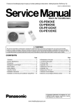
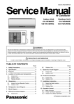
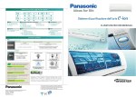
1
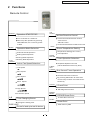
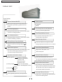
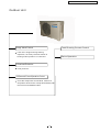
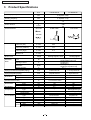
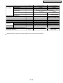
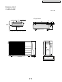
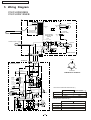
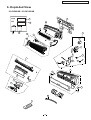
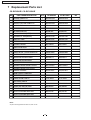
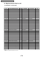
Order No: PHA-AG0701011A2
Air Conditioner
CS/CU-RE9GKE
CS/CU-RE12GKE
WARNING
This serv ice informati on is design ed for experienced repair technicians only a nd is not des igned for us e by the gene ral pu blic.
It d oes no t cont ain warnings or cau tions to advise non-tech ical ind ividua ls of potenti al dangers in attempting t o serv ice a product.
Pro ducts power ed by electricity should b e serviced or repaired only by experie nced profes sional technicians. Any a ttemp t to service
or r epair the pro duct o r products dealt with in th is service informa tion by anyon e else could result in serious injury or death.
CONTENTS
Page
1 Features
Page
-----------------------------------------
13
-----------------------------------------
14
-----------------------------------------
15
-----------------------------------------
16
--------------------------------------------------------
2
6 Exploded View
------------------------------------------------------
3
7 Replacement Parts List
-----------------------------------------
6
8 Exploded View
2 Functions
3 Product Specifications
4 Dimensions
-------------------------------------------------- 10
5 Wiring diagram
-------------------------------------------------- 12
R
9 Replacement Parts List
C Panasonic Home Appliances Air Conditioner
(Guangzhou) Co., Ltd. (PHA-AG) All rights reserved.
Unauthorized copying and distribution is violation of
law.
CS-RE9GKE / CU-RE9GKE / CS-RE12GKE / CU-RE12GKE
1 Features
■
■ High Efficiency
■
■ Enviromental Friendly (For Refrigerant : R410A Model)
Zero ozone depleting potential and low global
warming potential by using R410A refrigerant.
■
■ Powerful/Quiet operation mode.
■
■ Comfort Environment
Air filter with function to reduce dust and smoke
■
■ Auto Restart Control
Automatically restart after power failure
■
■ Rem ova ble and was hab le Front Pan el
■
■ 12-hour Timer Setting, 4 kinds of Timer mode.
D elay ON Timer
D elay OFF Tim er
D elay OFF-ON Tim er
D eley ON -OFF Tim er
■
■ Breakdown S elf Diagnosis functio n
2
CS-RE9GKE / CU-RE9GKE / CS-RE12GKE / CU-RE12GKE
2 Functions
Remote Control
AIR
SWING
OFF/ON
Operation START/STOP
MODE
Turn on/off the air conditi onor
Horizont al Airflow Direction Control
When stop the operat ion by pressing
-Auto Con trol
OFF /ON button,t he cursor key po ints
-Manual Control
to OFF.
Vertical Airfl ow Direction Manual Control
TEMP
Operation Mode Selection
Room Temperature Setting
Temperature Setti ng(16℃ to 30℃)
Automatic Mode Operation
A uto Operation
Heating Mode Ope ration
TIM ER
OFF/O N
Cooli ng Mode Operation
FAN
SPEED
Airflow Direction Control
Timer Operation Selection
Soft Dry Mode Operation
Indoor Fan Speed Selection
Stop/Start Operation Control
(set the ON/OFF Timer hourly later)
TIMER
SET/
CANCEL
Low Speed
Med- Speed
Set /Cancel Timer Operation
Set timer/Cancel the set timer
Med Speed
By pressing SET button for 5seconds
continuously to switch to set the sensor
Med+ Speed
sensitivity.
CHECK
Check Point
High Speed
Self diagnosis function
ERROE
RESET
Automatic Speed
A,B
ERROE Reset Point
To reset the i ndoor unit.
Time Changing Button
RESET
Reset Point
Change the setting time.
POWERFUL/QUIET
Clear memory data
Powerful and quiet swith button
3
CS-RE9GKE / CU-RE9GKE / CS-RE12GKE / CU-RE12GKE
Indoor Unit
Auto Switch
Button
Feature mode
Power Switch ON/OFF
When the remote control cannot be used or
for repairing and testing ,please use this
button.
Powerful
Quiet
Anti-freezing Control for the Evaporator
Force Cooling Operation
Cooling or Soft Dry Operation
Keep pressing this button for 5 seconds to start
the force cooling operation.
Time Delay Safety Control
Force Heating Operation
The unit will restart operation in 3-4
minutes after each pause.
Keep pressing this button for 8 seconds to start
the force heating operation.
Warm Booting Control
Different Remote Controlling Setting
Indoor fan starts running when indoor
Keep pressing this button for 11 to change
di fferent remote controlling setting(A
Mode.
piping temperature reaches 19 ℃ or above.
B)
Indoor Fan Speed Control
Signal Receiving Sound
Keep pressing this button for 16 seconds to turn
off or turn on the signal receiving sound or
High,Med+, Med, Med-,Low
H 14 A bno rmal ity Detection Mo de.
Auto Fan Speed
Airflow Direction Control
Operation Indication Lamps
Power (green)
Timer(orange)
Automatic Airflow Dir ection Control
Lights up in operation;
Blinks dur ing Hot Start
operation and
determining Auto
Operation mode
Light up in Timer Setting.
The louver automatically swings up and down
Five Manual Airflow Direction Control
Delayed On-timer Control
For cooling or soft dry mode, the unit
Blinks in Self Diagnosis Control
Air quality
Green
Orange
Red
starts 15 minutes before the set time with
the remote control, but for heating mode
30 minutes before the set time.
Operation Mode
Automatic Restart Control
Cooling/Heating/Soft Dry /Auto Operation
Operation is restarted after power failure
at previous setting mode.
4
CS-RE9GKE / CU-RE9GKE / CS-RE12GKE / CU-RE12GKE
Outdoor Unit
4-way Valve Control
Total Running Current Control
If the unit is stopped dur ing Heating
Oper ation, the 4- way v alve will remain in
heating mode operation for 3 minutes.
Deice Operation
Overload Protector
Inner protector
30 Seconds Forced Operation Control
Once the compressor i s activated, it does not
stop withi n 30 seconds. It stops immediatel y wi th
remote control ON/OFF button.
5
CS-RE9GKE / CU-RE9GKE / CS-RE12GKE / CU-RE12GKE
3
Product Specifications
CS-RE 9GK E
Unit
CU-RE9GKE
Cooling Capacity
kW
2.60(0.90-3.00)
Heating Capacity
kW
3.30(0.90-4.10)
Moi sture Rem oval
L /h
1.5
Single
230
50
Power Source
Phase
V
Cycle
Airflow Method
OU TLET
S IDE V IEW
TOP VIEW
INTA KE
Air Circulation Indoor Air (low)
m 3/min
5.94
-
Indoor Air (medium)
m 3/min
7.71
-
Indoor Air (high)
m 3/min
9.8
-
Outdoor Air
m 3/min
-
-
Electrical
Data
Cooling:high42,Low27
Cooling:high47
Heating:high42,Low27
Heating:high48
Cooling:750(190-1000)
Heating:820(170-1110)
Cooling:3.5
Heating:4.0
Cooling:3.46(3.00~4.73)
Heating:4.02(3.56~5.29)
3.7
G:half union3/8"
G:3-way valve3/8"
L:half union1/4"
L:2-way valve1/4"
G:gas side3/8"
G:gas side3/8"
L:liquid side1/4"
L:liquid side1/4"
14
0.5
1.9
3 core-wire/1.0mm 2
280
540
799
780
183
289
8.5
29
Rotary(1 cylinder)
Rolling piston type
Induction(6 poles)
750
dB(A)
Noise Level
Input
W
Running Current
A
EER/COP
W/W
Starting Current
A
Inch
Inch
Inch
Inch
mm
m
Piping Connection Port(Flare piping)
Piping Size(Flare piping)
Inner Diameter
Length
Power Supply Cord Length
(Number of core-wire)
Drain Hose
Height
Width
Depth
Dimensions
Net Weight
Compressor
m
mm
mm
mm
kg
Type
Motor
Air Circulation
Type
Rated output
W
type
type
Input
Rated Output
Low
Fan
Med
Speed
High
Cross-flow fan
Motor
Induction(8poles)
30
830±60
1070±60
1360±60
W
W
rpm
rpm
rpm
6
Propeller fan
Induction(6 poles)
25
730±60
CS-RE9GKE / CU-RE9GKE / CS-RE12GKE / CU-RE12GKE
Unit
Heat
Exchanger
CS-RE9GKE
Evaporator
Copper
Slot type
D escription
Tube Material
Fi n Type
(Plate fin configuration,forced draft)
Rows/Stage
2 x 15
20
FPI
Dimensions
mm
610x315x25.4
Refrigerant Control Device
Refrigeration Oil
(c.c)
-
Refrigerant (R410A)
Thermostat
Protection Device
Length
Capillary
C irculation
Inner Di ameter
g
mm
L/min
mm
Electronic Control
-
1X24
18.5
726x504x18.2
C apillary Tube
RB68A or Freol Alpha68M
840
sensor
Inner protector
600±10
8.15±0.2
1.3
P.P. H oneycomb
Air Filter
Refrigerant Circulation Control Device
Fan Motor Capacitor
CU-RE9GKE
Condenser
C opper
Corrugation type
Capi llary
μF , V
Specifications are subj ect to change without notice for further im pr ovem ent.
7
1.2μF , 450V
CS-RE9GKE / CU-RE9GKE / CS-RE12GKE / CU-RE12GKE
CS-RE12GKE
Unit
C U-RE12GKE
Cooling Capacity
kW
3.50(0.90-3.90)
Heating Capacity
kW
4.25(0.90-5.10)
Moi sture Rem oval
L /h
2.0
Single
230
50
Power Source
Phase
V
Cycle
Airflow Method
OU TLET
S IDE V IEW
TOP VIEW
INTA KE
Air Circulation Indoor Air (low)
m 3/min
6.79
-
Indoor Air (medium)
m 3/min
8.38
-
Indoor Air (high)
m 3/min
9.9
-
Outdoor Air
m 3/min
-
-
Electrical
Data
Cooling:high48
Cooling:high42,Low30
Heating:high42,Low33
Heating:high50
Cooling:1010(170-1200)
Heating:1140(150-1460)
Cooling:4.80
Heating:5.20
Cooling:3.46(3.25~5.29)
Heating:3.69(3.49~6.00))
4.9
G:half union3/8"
G:3-way valve3/8"
L:half union1/4"
L:2-way valve1/4"
G:gas side3/8"
G:gas side3/8"
L:liquid side1/4"
L:liquid side1/4"
14
0.5
14
3 core-wire/1.0mm 2
280
540
799
780
183
289
31
8.5
Rotary(1 cylinder)
Rolling piston type
Induction(6 poles)
750
-
dB(A)
Noise Level
Input
W
Running Current
A
EER/COP
W/W
Starting Current
A
Inch
Inch
Inch
Inch
mm
m
Piping Connection Port(Flare piping)
Piping Size(Flare piping)
Inner Diameter
Length
Power Supply Cord Length
(Number of core-wire)
Drain Hose
Height
Width
Depth
Dimensions
Net Weight
Compressor
m
mm
mm
mm
kg
Type
Motor
Air Circulation
Type
Rated output
W
type
type
Input
Rated Output
Low
Fan
Med
Speed
High
Cross-flow fan
Induction(8poles)
30
940±60
1160± 60
1370±60
Motor
W
W
rpm
rpm
rpm
8
Propeller fan
Induction(6 poles)
25
880±60
CS-RE9GKE / CU-RE9GKE / CS-RE12GKE / CU-RE12GKE
Unit
Heat
Exchanger
C S-RE 12GKE
Evaporator
Copper
Slot type
D escription
Tube Material
Fi n Type
(Plate fin configuration,forced draft)
2 x 15
2X24
20
17
Rows/Stage
FPI
Dimensions
mm
610x315x25.4
Refrigerant Control Device
Refrigeration Oil
(c.c)
-
Refrigerant (R410A)
Thermostat
Protection Device
Length
Capillary
C irculation
Inner Di ameter
g
mm
L/min
mm
Electronic Control
-
726
696 X504x36.4
C apillary Tube
RB68A or Freol Alpha68M
1040
Inner protector
310±10 565±20
11.3± 0.2 12.3±0.2
1.5
1.3
P.P. H oneycomb
Air Filter
Refrigerant Circulation Control Device
Fan Motor Capacitor
CU-RE12GKE
Condenser
C opper
Corrugation type
Capi llary
μF , V
Specifications are subject to change without notice for further improvement.
9
1.8μF , 450V
CS-RE9GKE / CU-RE9GKE / CS-RE12GKE / CU-RE12GKE
4 Dimensions
Indoor Unit
CS-RE9/12GKE
Unit : mm
Side view
Front View
183
Air inta ke
Rig ht Pip ing
Ho le
Left P iping
Hole
Air outlet
<Back View>
Gas Side
Installa tion Plate H ook
Liquid
Side
AUTO
HEAT
COOL
DRY
OFF
hr
DEL AY
OF F
ON
hr
DEL AY
OF F
ON
POW ERFUL/Q UIET
SELECT
SET/CANCEL
ER RO R R ESE T
(100)
56
(50)
(420)
16
Drain P ort
Installation plate (Front View)
A
B
(13 1)
(382 )
(631 )
10
(118)
CS-RE9GKE / CU-RE9GKE / CS-RE12GKE / CU-RE12GKE
Outdoor Unit
CU-RE9/12GKE
Unit : mm
<Top View>
10c m
or more
105
780
570
48
10 cm
or more
100cm
or more
INVERTER
320
352
11
57
CS-RE9GKE / CU-RE9GKE / CS-RE12GKE / CU-RE12GKE
5 Wiring Diagram
CS/CU-RE9GKE
CS/CU-RE12GKE
1
1
W
W
W
MO TOR
BR
W
W
SENSOR
(AI R TEMPERATURE.)
R
W
CN-STM
(W)
CN-DISP
(Y)
W
W
1
O
Y
5
P
W
W
W
ELECT RONIC
C ONTR OLLER
(DISPL AY,RE CEIVER )
WIREL ES S RE MOTE CONTROL
AU TO SW
W
SENSOR
(PIPING TEMP.)
W
W
W
15
15
ELECTRONIC
CONTROL LER
(MAIN)
CN- TH
(Y )
FU SE
T 2.5 A L 25 0V
POWER S UPPLY CORD
AC4
1
B
R
M OTOR
ZNR
4
BR
BL
A C1
W
AC2
R
BL
W
B
Y
FM
CN-FM
(W)
AC3
Y/G
INDOO R UNIT
1(1L )2(N) 3
TERMINAL
TERMINAL
YELLOW
1(
1 L)2(N) 3
BL
O UTDOOR UNIT
AC -WHT
(W HITE)
R
W
AC -BLK
(BLACK)
D ATA
(R ED)
BLUE
FUSE
RED
T20A L250V
G
TRADE MARK
F G I( GRE E N )
CO MPRESSO R TERMINAL
G
F G 2 (G R E E N )
SE N S OR
(A IR T E MP)
SE N S OR
(P IP IN G T E MP )
1
2 C N- T H
3 (W HI T E)
4
SE N S OR
(C OM P. T EM P )
1 C N- TA NK
3 (W HI T E )
C T101
+
CO IL C OM P
(4 -W AY VAVL E )
C N -H O T
(W H I T E )
Y
Y
OUTDOOR FAN MOTOR RESISTANCE(Ω)
G RY2
( GRAY)
GRY
G R Y1
( G R AY )
GRY
Fan Mot or
CAPACI TOR
B
Fm2
+
B
- DB 102
Fm1
Y
DB 101
Y
CU-RE9GKE
R EACTOR
+
Y-B(M)
Y-R (A)
+
N
L6L AHYF0000 1
423Ω
423Ω
686Ω
686Ω
COMPRESSOR RESISTANCE(Ω)
P
+ +
CONNECTING
CU-RE12GKE
L6 LAHY F00 00 1
C OMP RESSOR
(RED )
R
(BLU E)
B
(YELLO W)
Y
CONNECTING
Y/G
12
CU-PE9DK E
CU-PE12DKE
B 09 22 5 6
U -V
1.15 2
U-W
1.15 2
V-W
1.15 2
CS-RE9GKE / CU-RE9GKE / CS-RE12GKE / CU-RE12GKE
6. Exploded View
CS-RE9GKE / CS-RE12GKE
36
37
1
35
3
34
33
12
4
5
24
6
2
13
14
15
7
17
16
23
9
26
30
31
10
11
20
8
21
19
30
31
32
25
13
29
CS-RE9GKE / CU-RE9GKE / CS-RE12GKE / CU-RE12GKE
7 Replacement Parts List
CS-RE9GKE / CS-RE12GKE
NO
PART NAME&DESCRIPTION
CS-RE9GKE
Q'TY
CS-RE12GKE
1 CHASSIS COMPLETE
1
CWD50C1534
CWD50C1534
2 FAN MOTOR
1
ARW51G8P30AC
ARW51G8P30AC
3 CROSS FLOW FAN COMPLETE
1
CWH02C1054
CWH02C1054
4 EVAPORATOR
1
CWB30C2101
CWB30C2101
7 DISCHARGE GRILLE COMPLETE
1
CWE20C2701
CWE20C2723
8 AIR SWING MOTOR
1
CWA981091
CWA981091
9 HORIZONTAL VANE(LEFT)
1
CWE24C1189
CWE24C1189
10 HORIZONTAL VANE(RIGHT)
1
CWE24C1190
CWE24C1190
11 VERTICAL VANE
1
CWE24C1191
CWE24C1191
12 C-BOX
1
CWH14C5704
CWH14C5703
13 CONTROL BOARD
1
CWH102337
CWH102337
14 PARTICULAR PIECE
1
CWD932689
CWD932689
15 TERMINAL BOARD COMPLETE
1
CWA28C2279
CWA28C2279
16 POWER SUPPLY CORD COMPLETE
1
CWA20C2609
CWA20C2609
17 CONTROL BOARD
1
CWA73C2643
CWA73C2642
19 INDICATOR HOLDER-FRONT
1
CWD932717
CWD932717
20 INDICATOR HOLDER-BACK
1
CWD932718
CWD932718
21 INDICATOR PCB
1
CWA744835
CWA744835
23 CONTROL BOARD FRONT COVER
1
CWH131235J
CWH131235J
24 CONTROL BOARD TOP COVER
1
CWH131237
CWH131237
25 REMOTE CONTROL
1
CWA75C3077
CWA75C3077
26 FRONT GRILLE COMPLETE
1
CWE11C3768
CWE11C3768
29 AIR FILTER
2
CWD001168
CWD001168
30 SCREW-FRONT GRILLE
2
XTT4+16CFJ
XTT4+16CFJ
31 CAP-FRONT GRILLE
2
CWH521121
CWH521121
32 DRAIN HOSE
1
CWH851095
CWH851095
33 OPERATING INSTRUTIONS
1
CWF565612
CWF565594
34 OPERATING INSTRUTIONS
1
CWF565594
CWF565612
35 INSTALLATION INSTRUCTION
1
CWF613195
CWF613195
36 INSTALLATION INSTRUCTION
1
CWF613196
CWF613196
37 INSTALLATION PLATE
1
CWH361086
CWH361086
Note:
All parts are supplied from PHA-AG, P.R. China.
14
RE
CS-RE9GKE / CU-RE9GKE / CS-RE12GKE / CU-RE12GKE
8
Exploded View
CU-RE9GKE / CU-RE12GKE
29
42
37
34
28
31
4
27
2
5
6
25
3
26
11
24
7
39
23
33
12
19
32
18
20
17
14
36
8
34
10
13
38
9
15
16
21
1
15
CS-RE9GKE / CU-RE9GKE / CS-RE12GKE / CU-RE12GKE
9. Replacement Parts List
CU-RE9GKE / CU-RE12GKE
NO
PART NAM E&DESCRIPTION
1
CHASSIS ASS'Y
2
FAN MOTOR BRACKET
3
SCREW -FAN MOTOR BRACKET
4
FAN MOTOR
5
6
CU-RE9GKE
Q'TY
1
CU-RE12GKE
CWD50K2162A
CWD50K2162A
1
CWD54C1012
CWD54C1012
2
CWH551148A
CWH551148A
1
L6LAHYF00001
L6LAJYF00001
SCREW -FAN MOTOR MOUNT
4
CWH55406J
CWH55406J
PROPELLER FAN ASS'Y
1
CWH03K1034
CWH03K1034
7
NUT-PROPELLER FAN
1
CWH561036J
CWH561036J
8
COMPRESSOR
1
CWB092256
CWB092256
9
ANTI-VIBRATION BUSHING
3
CWH50077
CWH50077
10
NUT-COMPRESSOR MOUNT
3
CWH56000J
CWH56000J
11
CONDENSER
1
CWB32C2028
CWB32C2033
12
TUBE ASSY(3-WAY VALVE)
1
CWT01C4200
CWT01C4165
13
HOLDER COUPLING ASS'Y
1
CWH351040J
CWH351040J
14
4-W AY VALVE
2-W AY VALVE
1
CWB001037J
CWB001037J
15
1
CWB021251
CWB021251
16
3-W AY VALVE
1
CWB011308
CWB011308
17
STRAINER
1
CWB11094
CWB11094
18
TERMINAL COVER
1
CWH171039
CWH171039
19
NUT FOR TERMIANL COVER
1
7080300J
7080300J
20
SOUND PROOF BOARD
1
CWH151173
CWH151173
21
SOUND PROOF MATERIAL
1
CWG302433
CWG302433
23
REACTOR
1
CWA421050J
CWA421060J
24
CONTROL BOX COMPLETE
1
CWH14C5747
CWH14C5746
25
CONTROL BOARD CASING
TERMINAL BOARD ASS'Y
1
CWH102298
CWH102298
1
CWA28K1121
CWA28K1121
27
CONTROL BOARD COMPLETE
1
CWH14C5749
CWH14C5748
28
CONTROL BOARD CASING
1
CWH102298
CWH102298
29
26
COVER-CONTROL BOX
1
CWH131214
CWH131214
31
ELECTRONIC CONTROLLER
1
CWA73C2675
CWA73C2674
32
TUBE ASS'Y(CAPILLARY)
1
CWT01C3773
CWT01C4021
33
CAPILLARY
1
CWB15386
CWB15416
34
SENSOR COMPLETE(COMP)
1
CWA50C2209J
CWA50C2209J
35
SENSOR COMPLETE(PIPING)
1
CWA50C2282J
CWA50C2282J
36
V-COIL COMPLETE
1
CWA43C2179J
CWA43C2179J
37
TOP PLATE
1
CWE031054A
CWE031054A
38
CABINET FRONT PLATE
1
CWE06C1211
CWE06C1211
39
CABINET SIDE PLATE (R)
1
CWE041224A
CWE041224A
40
CABINET SIDE PLATE (L)
1
CWE041247A
CWE041247A
41
CONTROL BOARD COVER
1
CWH13C1161
CWH13C1161
42
HANDLE
1
CWE161001
CWE161001
N ote:
A ll par ts are s upplie d from PHA-AG, P.R. Ch ina.
16
RE