1
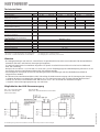
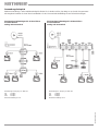
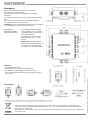
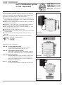
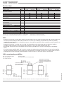
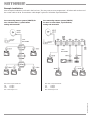
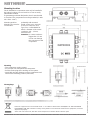
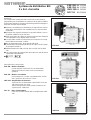
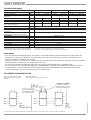
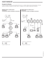
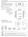
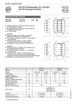
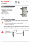
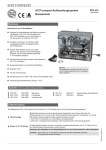
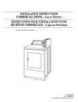
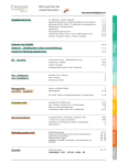
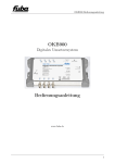
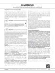
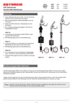
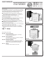
EXR 308 BN 273348
EXR 334 BN 273349
VWS 330 BN 230599
NCF 18 BN 230636
Sat-ZF-Verteilsystem
2 x Sat + terrestrisch
Zur Beachtung:
Die beschriebenen Geräte dienen ausschließlich der Installation
für Satelliten-Empfangsanlagen. Jegliche anderweitige Nutzung
oder Nichtbeachtung dieses Anwendungshinweises hat den
Verlust der Gewährleistung bzw. Garantie zur Folge.
Kaskadierfähiges Sat-ZF-Verteilsystem zur Verteilung von
Sat-ZF-Signalen (beide Polarisationen eines Satelliten) und
terrestrischen Signalen auf viele Receiver.
Terrestrischer Empfang auch bei ausgeschalteten
Sat-Receivern möglich.
Je nach Kabellänge können Systeme mit bis zu 16 Anschlüssen ohne Kaskadierverstärker aufgebaut werden.
Je Receiver ist nur eine Niederführung notwendig.
Für Twin-Receiver sind zwei Niederführungen notwendig.
Netzteil NCF 18 mit hohem Wirkungsgrad.
Umschaltung horizontal/vertikal über das Koaxialkabel durch
14/18 V-Versorgungsspannung.
Die Stromversorgung der LNB erfolgt je nach Anwendungsfall
über EXR 308, VWS 330 oder WFS 330.
Das Sat-ZF-Verteilsystem stimmt mit den z. Zt. gültigen
Anforderungen der Richtlinie 73/23/EWG und 89/336/EWG
überein.
EXR 308
K001
112
Beschreibung der Bauteile:
EXR 308 – End-Umschaltmatrix
für 8 Anschlüsse (wird pro Anlage 1 x benötigt),
komplett mit Netzteil NCF 18.
EXR 334 – Durchschleifmatrix
zur Erweiterung um jeweils 4 Anschlüsse, komplett
mit 3-fach Verbindungselement.
EXR 334
VWS 330 – Verteilnetzverstärker
komplett mit Netzteil NCF 18 und 3-fach-Verbindungselement. Je nach Kabellänge wird damit der
Ausbau um 3 zusätzliche EXR 334 ermöglicht.
VWS 330
935.1841/C/0805/1.4d
NCF 18 – Netzteil
als Beipack bei EXR 308 bzw. VWS 330.
Technische Daten
Typ
Bestell-Nr.
Frequenzbereich
Eingänge/Ausgänge/
Teilnehmer-Anschlüsse
Durchgangsdämpfung
Anschlußdämpfung
Verstärkung
Max. Ausgangspegel
(Störprodukt 3. Ordnung)
Max. Betriebspegel
Stromaufnahme aus dem Netzteil
Stromaufnahme aus dem
Receiver je Teilnehmer
Max. Stromentnahme über den
14 V-Anschluß (nicht kurzschlußfest)
Typ / Bestell-Nr.
Eingangsnennspannung
zul. Eingangsspannungsbereich
Spannung sekundär
Stromentnahme
Eingangsnennleistung
Schutzklasse/Schutzart
EXR 308
EXR 334
273348
47–862
950–2400
3/-/8
MHz
dB
dB
dB
dBµV
–
9
–
851)
dBµV
mA
mA
–
mA
47–862
–
10
–
852)
3
17
–
–
–
–
230599
950–2400
3/3/4
47–862
950–2400
3/3/-
3
13
–
852)
–
–
13
1101)
–
1053)
–
–
11
1102)
984)
150
1
40
20
120
–
150
–
300
NCF 18 / 230636
230 (50–60 Hz)
198–253
18 ± 5%
max. 650
typ. 14,5
II (schutzisoliert)/IP 30
V~
V~
V=
mA
W
) 60 dB KMA / 3-Sender-Meßverfahren nach DIN 45004 B
) 35 dB IMA / 2-Sender-Meßverfahren nach EN 50083-3
VWS 330
273349
) bei Belegung mit 6 TV-Kanälen und FM
) bei Belegung mit 32 TV-Kanälen pro Polarisation
1
3
2
4
Hinweise
– Bei Anlagenplanungen mit mehr als 4 Anschlüssen ist grundsätzlich einmal die Umschaltmatrix EXR 308 (enthält das
Netzteil für die LNB- und Matrizen-Versorgung) einzuplanen.
Sie wird als letzte Matrix im Verteilnetz eingesetzt. Für jeweils 4 zusätzliche Anschlüsse ist eine Durchschleifmatrix
EXR 334 notwendig.
Beispiel: 16 Anschlüsse = 1 x EXR 308 + 2 x EXR 334. Je nach Empfangspegel und Kabeldämpfung können bis zu 16
Anschlüsse ohne Sat-Verteilnetzverstärker VWS 330 realisiert werden.
– Nicht belegte HF-Ausgänge müssen zur Einhaltung der EMV-Anforderungen mit Abschlußwiderstand EMK 03
abgeschlossen werden.
– Bei Einsatz eines Verteilnetzverstärkers VWS 330 erfolgt die LNB-Stromversorgung und die Versorgung der davorgeschaltenen Matrizen vom Netzteil des Verstärkers aus. Die Stromversorgung der nachgeschalteten Matrizen kann
sowohl von der End-Umschaltmatrix EXR 308 wie auch vom 2. DC-Anschluß des Verstärkers erfolgen.
(= zugleich interne Versorgungsspannung von VWS 330)
Möglichkeiten der LNB-Stromversorgung
650 mA für LNB
Davon max. 300 mA über den 14 V-Anschluß
Zur Ermittlung des gesamten Strombedarfes sind alle aktiven Komponenten zu berücksichtigen.
935.1841/C/0805/2.4d
650 – 150 = 500 mA für LNB
Davon max. 200 mA über
den 14 V-Anschluß
Anwendungsbeispiele
Weitere Anwendungs- und Installationsbeispiele finden Sie in der Broschüre „Der Weg zu noch mehr Programmen“.
Alle Angaben beziehen sich auf das Koaxialkabel LCD 90. Die maximale Kabellänge ist auf 2150 MHz bezogen.
Sat-Gemeinschaftsanlage bis 20 Anschlüsse
2 Polarisationen
analog und terrestrisch
Mindestpegel am Eingang von EXR 334:
Mindestpegel am Eingang von EXR 334:
Sat
VHF
UHF
Sat
VHF
UHF
75 dBµV
80 dBµV
90 dBµV
Maximale Kabellänge: 42 m
75 dBµV
80 dBµV
90 dBµV
Maximale Kabellänge: 50 m
935.1841/C/0805/3.4d
Sat-Gemeinschaftsanlagen bis 16 Anschlüsse
2 Polarisationen
analog und terrestrisch
Montageort
Das Sat-ZF-Verteilsystem darf nur in trockenen
Innenräumen montiert werden.
Nicht auf oder an leicht entzündlichen Materialen
montieren.
Zur Geräteentwärmung muß freie Luftzirkulation möglich
sein.
Die Geräte sind mit einer Potentialausgleichsleitung
(Cu mindestens 4 mm2) zu versehen.
Achtung: Die Sicherheitsbestimmungen nach EN 50083-1
+ A1 und EN 60065 + A11 sind zu beachten.
Vorzugsweise Wandmontage.
Holzschrauben, max. 4 mm Ø
Schraubkupplung 75 Ω (Serie F)
nach EN 60169-24.
Zulässiger Durchmesser des
Kabelinnleiters: 0,6 – 1,2 mm,
gratfrei
Achtung Bei größerem Durch
messer des Kabelinnenleiters als
1,2 mm bzw. Grat können die
Gerätebuchsen zerstört werden.
Montage
– Stromführendes Gerät!
– Nicht öffnen, nicht am Gerät manipulieren.
– Bei Arbeiten an der Anlage Netzstecker ziehen.
– Auf ausreichenden Abstand und Montagelage achten
(siehe Abb.)
Steckdose
Montagelage
Elektronische Geräte gehören nicht in den Hausmüll, sondern müssen - gemäß Richtlinie 2002/96/EG DES
EUROPÄISCHEN PARLAMENTS UND DES RATES vom 27. Januar 2003 über Elektro-und Elektronik-Altgeräte
fachgerecht entsorgt werden.
Bitte geben Sie dieses Gerät am Ende seiner Verwendung zur Entsorgung an den dafür vorgesehenen öffentlichen
Sammelstellen ab.
KATHREIN-Werke KG · Anton-Kathrein-Straße 1–3 · Postfach 10 04 44 · D-83004 Rosenheim · Deutschland · Telefon (0 80 31) 18 40 · Telefax (0 80 31) 18 43 06
935.1841/C/0805/4.4d/SKS Irrtum und technische Änderungen vorbehalten.
Montagelage:
Befestigungsmittel:
Verbindungsstecker:
SAT IF Distribution System
2 x Sat + terrestrial
EXR 308 BN 273348
EXR 334 BN 273349
VWS 330 BN 230599
NCF 18 BN 230636
The components mentioned ih these instructions are only destined for installation in satellite reception systems. Any other use
or the non-observance of the insdtructions will entail the loss of
guarantee or the liability claim on the manufacturer.
Cascadeable Sat IF distribution system for the distribution of
Sat IF signals (both polarisations from a satellite) and terrestrial
signals on to many receivers.
Terrestrial range is fully passive to allow reception also without
switched-on Sat receiver.
Depending on the cable length, it will be possible to feed the
signals to 16 subscribers without using an amplifier.
Each receiver needs only one coaxial cable leading to it. Twin
receivers will need two cables.
High efficiency power supply unit NVCF 18.
Horizontal/vertical switch-over via the coaxial cable with 14/18
V supply voltage.
Remote feeding of LNBs either via EXR 308, VWS 330 or
WFS 330.
The Sat IF components fulfil the requirements of the valid
regulations 73/23/EEC and 89/336/EEC.
EXR 308
K001
112
Description of the components:
EXR 308 – End-line switching matrix
for 8 subscribers (is needed once per system)
supplied with power supply unit NCF 18.
EXR 334 – Through-line switching matrix
allows one to extend a system wit another 4 subscriber points, supplied with 3-way connection element.
VWS 330 – Network Amplifier
with separate power supply unit NCF 18 and 3-way
connection element. Allows one to extend the network with 3 additional 4-way matrices EXR 334 (dependent on cable loss).
EXR 334
VWS 330
935.1841/C/0805/1.4e
NCF 18 – Power supply unit
Is in the scope of delivery of EXR 308 and VWS 330.
Technical data
Type
EXR 308
Order Nr.
273348
Frequency range
MHz
47–862
950–2400
Inputs/Outputs/
3/-/8
Subscriber connections
Through loss
dB
–
–
Tap loss
dB
9
10
Gain
dB
–
–
852)
max. output level
dBµV
851)
(3rd order prod.)
max. operation level
dBµV
–
–
Current drain from power unit
mA
150
Current drain from receiver
mA
1
each subscriber
max. current drain form DC connection
mA
150
(not short-circuit proof)
Type / Order Nr.
NCF 18 / 230636
nominal input voltage
V~
230 (50–60 Hz)
admissible input voltage range
V~
198–253
secondary voltage V=
18 ± 5%
Current drain
mA
max. 650
Consumption
W
typ. 14,5
Safety class/Protection category
II (Safety insulation)/IP 30
) 60 dB X. mod. / 3 transmitter measurement method B acc. to DIN 450043
) 35 dB I. mod./ 2 transmitter measurement method acc. to EN 50083-3
EXR 334
VWS 330
273349
47–862
950–2400
3/3/4
3
17
–
–
–
47–862
3
13
–
852)
–
–
13
1101)
–
1053)
230599
950–2400
3/3/–
–
11
1102)
984)
40
20
120
–
–
300
) distributing 6 TV channels and FM signals.
) distributing 32 TV channels each polarisation.
1
3
2
4
Note
– Systems for more than 4 subscribers need be planned with at least one switching matrix EXR 308 (a power supply unit
for remote power feeding to LNBs and the matrices is in the scope of delivery of EXR 308. The matrix is generally
installewd as the final matrix in a distribution system. A through-line matrix EXR 334 is needed for system extension to
another four subscribers.
Example: 16 receivers = 1 x EXR 308 + 2 x EXR 334- Depending on the signal level and the cable loss, it will be
possible to feed the signals to 16 receivers without having to use a Sat matrix amplifier VWS 330.
– Not needed outputs have to be terminated with the resistor type EMK 03 to assure electromagnetic compatibility
(EMC).
– If a matrix system amplifier VWS 330 is used in a system, the LNB and the switching matrices in front of the amplifier
receive the operating power from the power unit of the amplifier. The amplifier and the post-circuited matrices can be
powered either via the switching matrix EXR 308 or via the second DC connection point on the amplifier.
LNB current supply possibilities
650 mA for LNB
max. 300 mA from 14 V connection point
Connection point for
LNB supply voltage or
pre-circuited matrices
Alternative connection
point for power supply to
amplifier or matrices from
NCF 18
When calculating the totally required supply voltages, the current drain of all active components in the system must be taken into account.
935.1841/C/0805/2.4e
650 – 150 = 500 mA for LNB
max. 200 mA from
14 V connection point
Example Installations
More example installations are found in the brochure „The easy route to more programmes“. All values refer to the use of
the coaxial cable LCD 90. The maximum cable length is given for 2150 MHz signal distribution.
Sat community antenna system (SMATV) for
max. 16 subscribers, 2 polarisations
analog and terrestrial
terrestrial
Antenna
Sat community antenna system (SMATV)
for max. 20 subscirbers, 2 polarisations,
analog and terrestrial
SAT-IF
terrestrial
Antenna
SAT-IF
Min. level on input of EXR 334:
Min. level on input of EXR 334:
Sat
VHF
UHF
Sat
VHF
UHF
Max. cable length: 42 m
75 dBµV
80 dBµV
90 dBµV
Max. cable length: 50 m
935.1841/C/0805/3.4e
75 dBµV
80 dBµV
90 dBµV
Mounting location
The IF distribution components must only be installed in
dry indoor locations. Do not install on or near to easily
inflammable material.
To guarantee good heat dissipation, the air must be able
to circulate. The components must be grounded (Cu wire
min. diam. 4 mm2)
Mounting position:
Mounting accessories:
Connections:
preferably wall mounted.
Wood screws, max. 4 mm Ø
Screw-on connector 75 Ω,
Type F acc. to EN 60169-24.
Admis. diameter of the centre
conductor: 0,6 – 1,2 mm,
free from burr.
Attention: A centre conductor
bigger than 1.2 mm
or burr can damage
the connectors of the
component.
Mounting
– The component carries current!
– Do not open nor manipulate the component.
– Pull the mains plug when working on the system.
– Install with enough distance to other components and
observe the mounting position (see illustr.)
Antenna socket
Electronic equipment is not household waste – in accordance with directive 2002/96/EC OF THE EUROPEAN
PARLIAMENT AND THE COUNCIL of 27th January 2003 on used electrical and electronic equipment, it must be
disposed of properly.
At the end of its service life, take this unit for disposal at a relevant official collection point
KATHREIN-Werke KG · Anton-Kathrein-Straße 1–3 · Postfach 10 04 44 · D-83004 Rosenheim · Deutschland · Telefon (0 80 31) 18 40 · Telefax (0 80 31) 18 43 06
935.1841/C/0805/4.4e/SKS Subject to technical changes!
Montagelage
EXR 308 BN 273348
EXR 334 BN 273349
VWS 330 BN 230599
NCF 18 BN 230636
Système de distribution BIS
2 x Sat + terrestre
Remarque:
Les composants mentionnés dans cette notice sont destinés
uniquement pour l’installation en systèmes de réception satellite.
Toute auutre utilisation entraine la perte de garantie et dégage le
fabircant de toute responsabilité.
Système cascadable pour distribution de signaux BIS et terrestres (deux polarisations d’un satellite) vers un grand nombre
d’abonnés.
Réception des signaux terrestres est possible même si aucun
récepteur satellite n’est en fonction.
Selon la longueur du câble, les signaux peuvent être distribués
à 16 utilisateurs sans amplificateur cascadé.
Un seul câble coaxial est nécessaire par récepteur. Les récepteurs TWIN nécessistent 2 câbles.
Bloc d’alimentation NCF 18 de grande efficacité.
Commutation horizontale/verticale par le câble coaxial à partir
du récepteur (14/18 V).
Téléalimentation du LNB par EXR 308, ou VWS 330 ou WFS
330.
Les composants du système BIS répondent aux spécifications
73/23/CEE et 89/336/CEE.
EXR 308
K001
112
Description des composants:
EXR 308 – Matrice terminale
pour 8 abonnés, livrée avec bloc d’alimentation
séparé NCF 18 (une matrice est nécessaire par
système)
EXR 334 – Matrice cascadable
pour extension à 4 sorties complémentaires, livrées
avec une pièce de jonction à 3 voies.
EXR 334
VWS 330 – Amplificateur d’extension
livré avec bloc d’alimentation séparé NCF 18 et une
pièce de jonction à 3 voies.
Selon la longueur du câble, permet l’extension du
système avec 3 EXR 334.
VWS 330
935.1841/C/0805/1.4f
NCF 18 – Bloc d’alimentation
Livré avec la matrice EXR 308 et l’amplificateur VWS
330.
Données techniques
Type
No.
Gamme de fréquency
Entrées/Sorties/
Abonnées
Affaiblissement de passage
Affaiblissement de raccordement
Gain
Niv. de sortie, max.
(prod. d’inter. 3ème ord.)
Niveau d’opération, max.
Courant consommé à partir de l’aliment.
Courant consommé à partir du récepteur
par abonnée
Décharge de courant par la borne de 14 V
(ne pas protége contre les court-circuits)
Alimentation
Tension d’entrée, nom.
Plage de tension d’entrée admis.
Tension sec.
Courant consommé
Consommation
Classe de protection/Catégorie de protection
MHz
EXR 308
EXR 334
273348
47–862
950–2400
3/-/8
273349
47–862
950–2400
3/3/4
dB
dB
dB
dBµV
–
9
–
851)
dBµV
mA
mA
–
mA
–
10
–
852)
3
17
–
–
–
–
47–862
3
13
–
852)
–
–
13
1101)
–
1053)
230599
950–2400
3/3/–
–
11
1102)
984)
150
1
40
20
120
–
150
–
300
NCF 18 / 230636
230 (50–60 Hz)
198–253
18 ± 5%
max. 650
typ. 14,5
II (Isolation protectrice)/IP 30
V~
V~
V=
mA
W
) 60 dB M /messures à 3 porteuses suivant DIN 45004 B
) 35 dB IM /messures à 2 porteuses suivant EN 50083-3
VWS 330
) par rapport à la loi de pondération avec 6 canaux TV + la FM
) par rapport à la loi de pondération avec 32 canaux par polarisation
1
3
2
4
Remarques
– Pour les systèmes de distribution BIS, une matrices cascadable (Modèle final EXR 308 livré avec alimentation) est
nécessaire. La matrice est utilisée en tant que matrice terminale. Pour l’extension à 4 sorties complèmentaires, la
matrice d’extension EXR 334 est nécessaire.
Exemple: 16 sortie = 1 x EXR 304 + 2 x EXR 334. Selon le niveau d’entré et l’atténuation du câble, les signaux peuvent
être distribués à 16 utilisateurs sans amplificateur VWS 330.
– Les sorties non-utilisées doivent être fermées par une charge 75Ω type EMK 03 (compatibilité CEM).
– En cas d’utilisation d’un amplificateur VWS 330, la téléalimentation du LNB et des matrices amont se fait à partir de
son alimentation. L’amplificateur et les autres matrices pourront être alimentées par la matrice de commutation
terminale EXR 308 ou par la deuxième borne CC de l’amplificateur.
Possibilités d’alimentation LNB
650 – 150 = 500 mA pour LNB
Dont 200 mA max. via la borne
de 14 V
650 mA pour LNB
Dont 300 mA max. via la borne de 14 V
Point de raccordement alternativ pour alimenter
l’amplificateur ou les matrices par l’unité NCF 18
Le calcul d’alimentation LNB doit prendre en considération le courant consommé par tous les composants actifs du système BIS.
935.1841/C/0805/2.4f
Point de raccordement
pour alimenter le LNB
ou les matrices en aval
Exemples d’utilisation
D’autres exemples d’utilisation se trouvent dans la brochure „La solution simple pour plus de programmes“. Tous les
données se refèrent à l’utilisation du câble LCD 90. La longueur max. du câble est valable pour 2150 MHz.
Antenne collective satellite jusqu’à
16 abonnées
2 polarisations, signaux analogiques et terrestres
Antenne
terr.
Antenne collective satellite jusqu’à
20 abonnées
2 polarisations, signaux analogiques et terrestre
BIS
Antenne
terr.
BIS
Niveau min. à l’entrée EXR 334:
Longueur min. à l’entrée EXR 334:
Sat
VHF
UHF
Sat
VHF
UHF
Longueur de câble 42 m max.
75 dBµV
80 dBµV
90 dBµV
Longueur de câble 50 m max.
935.1841/C/0805/3.4f
75 dBµV
80 dBµV
90 dBµV
Lieu de montage
Les composants du système BIS sont prévus pour
l’installation à l’intéreur. Ne montez pas les composants
sur ou près de matériaux facilement inflammables. Pour
assurer une bonne dissipation de la chaleur, l’air doit être
en mesure de pouvoir circuler. Les composants doivent
être mis à la terre (fil de cuivre d’au moins 4 mm2).
Attention:
Observez les prescriptions de sécurité selon
EN 500-83-1 + A 1 et EN 60065 + A 11.
Position de montage:
En préférance sur un mur.
Accessoires de montage:Vis à bois, max. 4 mm Ø
Connecteurs:
Couplage à visser 75 Ω
type F selon EN 60169-24.
Diamètre admis. du conducteur
intérieur: 0,6 – 1,2 mm,
libre de bavure.
Attention: Un diamètre dépassant 1,2 mm ou de la
bavure, puisse
endommager les
embases.
Prise d’antenne
Positions de montage
Les appareils électroniques ne doivent pas être mis dans la poubelle de la maison, mais doivent être recyclés
correctement selon la directive 2002/96/EG DU PARLEMENT ET DU CONSEIL EUROPEEN du 27 janvier 2003
concernant les appareils électroniques et électriques usagés.
Nous vous prions de mettre cet appareil à la fin de son utilisation dans un emplacement prévu pour son recyclage.
KATHREIN-Werke KG · Anton-Kathrein-Straße 1–3 · Postfach 10 04 44 · D-83004 Rosenheim · Deutschland · Telefon (0 80 31) 18 40 · Telefax (0 80 31) 18 43 06
935.1841/C/0805/4.4f/SKS Nous nous reservons le droit de toutes modifiaitons techinques.
Positions de montage
– Le composant est sous tension.
– N’ouvrez pas, ne munipulez pas le composant.
– Lors du travail sur le réseau, tirez le câble secteur.
– Gardez une distance suffisante vers d’autres objects
(voir illustr.).