1
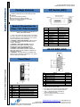
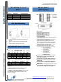
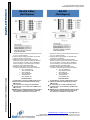
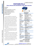
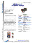
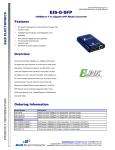
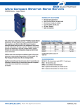
B&B ELECTRONICS p/n 7207r4 485DRCI-0812ds page 1/5 ©2008 B&B Electronics. All rights reserved 485DRCI Industrial RS-232 to RS-422/485 Converter Data Rates up to 115.2 Kbps 10 – 48 VDC Input Power Range Wide Operating Temperature 3-Way 2000V Optical Isolation Modbus ASCII/RTU Compatible UL Class 1 Division 2 Specifications The Ilinx™485DRCI is our premium Industrial RS-232 to RS-422/485 Converter. Designed for rugged industrial use, it is UL approved and certified for operation in Class 1 Division 2 environments. This DIN rail mountable converter optically Industrial Bus Serial Technology TD, RD, GND Data A(-), Data B (+), GND TDA(-), TDB(+), RDA (-), RDB(+), GND DB9 Female (DCE) Removable Terminal Block, 28 to 14 AWG 1.2 to 115.2 Kbps 2000 V, 3-Way (Input, Output, Power) 600 W Peak Power Dissipation Clamping time < 1 pico-second MODBUS ASCII / RTU Source Input Voltage Power Consumption Connector Power External 10 to 48 VDC 960 mW Removable Terminal Block, 28 to 14 AWG LED Indicators Dimensions Enclosure Weight Mechanical Transmit, Receive, and Power 4.5 x 1.3 x 4.9 in (11.4 x 3.3 x 12.4 cm) 35mm DIN Mount, Plastic, IP30 0.45 lbs (204.12 g) Op TEMP Storage TEMP Op Humidity Environmental - 40 to 176 °F (-40 to 80 °C) - 40 to 185 °F (-40 to 85 °C) 0 to 95% Non-condensing Approvals UL File Number MTBF MTBF Calc. Method Regulatory FCC, CE, cUL, Class 1 Division 2 E222870 (C1 D2 E245458) 254617 Parts Count Reliability Prediction RS-232 RS-485 2-Wrie RS-422/485 4-Wire RS-232 CON. RS-422/485 CON. Data Rate Isolation Surge Protection isolates and converts unbalanced, full or half-duplex RS-232 signals to balanced RS-422/485 signals at baud rates up to 115.2 Kbps. In addition to optical isolation, the unit has surge suppression on the RS422/485 lines. Featuring Automatic Send Data Control circuitry, it does not require special software PRODUCT INFORMATION control of handshake signals in RS-485 mode. The removable terminal blocks for power and RS422/485 signals make wiring easy. It is powered by a supply voltage of 10 to 48 VDC which is isolated from all data and signal ground lines. Configuration is made easy with a 12 position DIP switch on the bottom of the converter. Remember, when it comes to reliable communications in harsh industrial environments, Type Size Temperature Terminal Torque Ordering Information B&B Electronics’ Ilinx™ brand converters and isolators are your number one choice. Class 1 DIV 2 Wiring Solid Copper Only 28 to 14 AWG 105°C (221 °F) Minimum 0.5 Nm (Newton-meters) 485DRCI Accessories MDR-20-24 Ind. RS-232 to RS-422/485 Converter Ind. 24VDC 1A Slimline Power Supply www.bb-elec.com [email protected] [email protected] International Office: 707 Dayton Road PO Box 1040 Ottawa, IL 61350 USA 815-433-5100 Fax 433-5104 European Office: Westlink Commercial Park Oranmore Co. Galway Ireland +353 91 792444 Fax +353 91 792445 B&B ELECTRONICS p/n 7207r4 485DRCI-0812ds page 2/5 ©2008 B&B Electronics. All rights reserved DIP Switch (SW1) Package Contents 485DRCI Industrial RS-232 to RS-422/485 Converter Datasheet Power Terminal Block (installed) RS-422/485 Terminal Block (installed) If any item is missing or damaged, contact B&B Electronics for a replacement Special Precautions for Class 1 Div 2 Environment Special Instructions for Installation and Operation in a Class 1 DIV 2 Environment. 1. Power, input / output (I/O) wiring must be in accordance with Class 1 Division 2 wiring methods [Article 501.10(B) of the National Electrical Code, NFPA70] and in accordance with the local authority having jurisdiction. 2. WARNING – EXPLOSION HAZARD: SUBSTITUTION OF COMPONENTS MAY IMPAIR SUITABILITY FOR CLASS 1, DIVISION 2. 3. WARNING – EXPLOSION HAZARD: WHEN IN HAZARDOUS LOCATIONS, TURN OFF POWER BEFORE REPLACING OR WIRING MODULES 4. WARNING – EXPLOSION HAZARD: DO NOT DISCONNECT EQUIPMENT UNLESS POWER HAS BEEN SWITCHED OFF OR THE AREA IS KNOWN TO BE NON-HAZARDOUS. 5. WARNING – THIS APPARATUS IS SUITABLE FOR USE IN CLASS 1, DIVISION 2, GROUPS A, B, C, AND D, OR UNCLASSIFIED LOCATIONS. Pos 1 2 3 4 5 6 7 8 9 10 11 12 ON RS-485 Half Duplex 2-Wire 2-Wire Termination In TX Bias In RXBias In 2400 baud 4800 baud 9600 baud 19.2 k baud 38.4 k baud OFF RS-422 Full Duplex 4-Wire 4-Wire Termination Out TX Bias Out RX Bias Out RS-232 DB9F (DCE) PRODUCT INFORMATION Front Panel 1 2 Power TB RD LED 3 4 5 DB9 F 422/485 TB TD LED 6 7 Power LED Dip Switch 2 Position, Removable Red, Flashes when RS-422/485 Data Received RS-232 (Wired DCE) 5 Position, Removable Red Flashes when RS-422/485 Data Transmitted Red, ON When Power Applied 12 Position Pin 1 2 3 4 5 6 7 8 9 Signal Receive Line Signal Detector (DCD) Receive Data (RD) Transmit Data (TD) DTE Ready (DTR) Signal Ground (SG) DCE Ready (DSR) Request to Send (RTS) Clear to Send (CTS) Ring Indicator (RI) Direction --OUTPUT INPUT ------------- 1. DB9 Female Connector is DCE. 2. Pin 2 (RD) is the Converter’s RS-232 Data Output. 3. Pin 3 (TD) is the Converter’s RS-232 Data Input. 4. Pins 1, 4, and 6 (DCD, DTR, and DSR) are jumpered together internally. 5. Pins 7 and 8 (RTS and CTS) are jumpered together internally. www.bb-elec.com [email protected] [email protected] International Office: 707 Dayton Road PO Box 1040 Ottawa, IL 61350 USA 815-433-5100 Fax 433-5104 European Office: Westlink Commercial Park Oranmore Co. Galway Ireland +353 91 792444 Fax +353 91 792445 B&B ELECTRONICS p/n 7207r4 485DRCI-0812ds page 3/5 ©2008 B&B Electronics. All rights reserved RS-422/485 Terminal Block Terminal A B C D E RS-485 2-Wire GND Data B(+) Data A(-) ----- RS-485 2-Wire (Half Duplex) RS-422/485 4-Wire GND RDB(+) RDA(-) TDB(+) TDA(-) DIN Rail Mounting 1. Angle the top portion of the DIN mount over the top of DIN Rail. 2. Move the converter so that it is parallel with the DIN Rail. 3. Snap the bottom of the DIN mount in place. PRODUCT INFORMATION RS-422/485 Baud / Timeout Baud (Kbps) 2.4 4.8 9.6 19.2 38.4 SW1 8 ON OFF OFF OFF OFF Switch Selectable SW1 SW1 SW1 9 10 11 OFF OFF OFF ON OFF OFF OFF ON OFF OFF OFF ON OFF OFF OFF SW1 12 OFF OFF OFF OFF ON Timeout (ms) 4.16 2.08 1.04 0.580 0.260 Resistor Selectable Baud Timeout (Kbps) SW1-8 through 12 R-11 Value (ms) 1.2 OFF 820 KΩ 8.33 57.6 OFF 16 KΩ 0.176 115.2 OFF 8.2 KΩ 0.087 1. Pre-defined baud rates are set using SW1 positions 8 through 12. 1. Loosen the screws to open the TB lead clamps for the A, B, and C terminals. 2. Insert the RS-485 2-Wire signal leads. The terminal board accepts 28 to 14 AWG wire. 3. Tighten the screws to close the TB lead clamps. Ensure the clamps hold the leads securely. However, do not over tighten. For Class 1 DIV 2 installations, ensure the wiring is in accordance with the special precautions and the specification table. 4. Configure the DIP Switch on the bottom of the converter for RS-485 2-Wire operation (see above). X. ON = Termination IN OFF=Termination OUT Y. ON=TX Bias IN OFF=TX Bias OUT Z. ON=RX Bias IN OFF=RX Bias OUT Installation Notes: In 2-Wire mode, Terminal B is tied to Terminal D and Terminal C is tied to Terminal E with DIP Switch SW1-3 and SW1-4. If Termination is required, a 120Ω resistor can be placed across the D and E terminals by setting SW1-5 to ON. This converter has 1.2 KΩ pull-up/down bias resistors built in. To use this bias, set SW1-6 and SW1-7 to ON. B&B Electronics’ RS-485 Application Note contains more information about termination and biasing. This reference is available on our web site. 2. Resistor Selectable baud rates are set by inserting a through-hole resistor (R-11) on the circuit board. 3. WARNING – EXPLOSION HAZARD: SUBSTITUTION OF COMPONENTS MAY IMPAIR SUITABILITY FOR CLASS 1, DIVISION 2. www.bb-elec.com [email protected] [email protected] International Office: 707 Dayton Road PO Box 1040 Ottawa, IL 61350 USA 815-433-5100 Fax 433-5104 European Office: Westlink Commercial Park Oranmore Co. Galway Ireland +353 91 792444 Fax +353 91 792445 B&B ELECTRONICS p/n 7207r4 485DRCI-0812ds page 4/5 ©2008 B&B Electronics. All rights reserved RS-485 4-Wire (Full Duplex) RS-422 (Full Duplex) PRODUCT INFORMATION 1. Loosen the screws to open the TB lead clamps for the A, B, C, D, and E terminals. 2. Insert the RS-485 4-Wire signal leads. The terminal board accepts 28 to 14 AWG wire. 3. Tighten the screws to close the TB lead clamps. Ensure the clamps hold the leads securely. However, do not over tighten. For Class 1 DIV 2 installations, ensure the wiring is in accordance with the special precautions and the specification table. 4. Configure the DIP Switch on the bottom of the converter for RS-485 2-Wire operation (see above). X. ON = Termination IN OFF=Termination OUT Y. ON=TX Bias IN OFF=TX Bias OUT Z. ON=RX Bias IN OFF=RX Bias OUT Installation Notes: If Termination is required, a 120Ω resistor can be placed across the D and E terminals by setting SW1-5 to ON. This converter has 1.2 KΩ pull-up/down bias resistors built in. To use this bias, set SW1-6 and SW1-7 to ON. B&B Electronics’ RS-485 Application Note contains more information about termination and biasing. This reference is available on our web site. 1. Loosen the screws to open the TB lead clamps for the A, B, C, D, and E terminals. 2. Insert the RS-422 signal leads. The terminal board accepts 28 to 14 AWG wire. 3. Tighten the screws to close the TB lead clamps. Ensure the clamps hold the leads securely. However, do not over tighten. For Class 1 DIV 2 installations, ensure the wiring is in accordance with the special precautions and the specification table. 4. Configure the DIP Switch on the bottom of the converter for RS-485 2-Wire operation (see above). X. ON = Termination IN OFF=Termination OUT Y. ON=TX Bias IN OFF=TX Bias OUT Z. ON=RX Bias IN OFF=RX Bias OUT Installation Notes: If Termination is required, a 120Ω resistor can be placed across the D and E terminals by setting SW1-5 to ON. This converter has 1.2 KΩ pull-up/down bias resistors built in. To use this bias, set SW1-6 and SW1-7 to ON. B&B Electronics’ RS-485 Application Note contains more information about termination and biasing. This reference is available on our web site. www.bb-elec.com [email protected] [email protected] International Office: 707 Dayton Road PO Box 1040 Ottawa, IL 61350 USA 815-433-5100 Fax 433-5104 European Office: Westlink Commercial Park Oranmore Co. Galway Ireland +353 91 792444 Fax +353 91 792445 B&B ELECTRONICS p/n 7207r4 485DRCI-0812ds page 5/5 ©2008 B&B Electronics. All rights reserved Loop Back Test Power 1. Loosen the screw to open the terminal block lead clamp. 2. Insert the power lead. TB will accept 28 to 14AWG wire. 3. Tighten the screw to close the terminal block lead clamp. Ensure the clamp holds the lead securely. However, do not over tighten. For Class 1 DIV 2 installations, ensure wiring is in accordance with the special precautions and specification table. 1. Configure the converter for RS-485 4-Wire mode and the desired baud rate. 2. Place a jumper wire between the B and D terminals and the C and E terminals. 3. Connect a PC to the RS-232 port. 4. Using Hyper Terminal or similar program, connect to the appropriate COM port. Set the baud rate to match the converter. Ensure Hyper Terminal local echo is OFF. 5. Transmit data. If the same data is returned, the test is good. PRODUCT INFORMATION Mechanical Diagram www.bb-elec.com [email protected] [email protected] International Office: 707 Dayton Road PO Box 1040 Ottawa, IL 61350 USA 815-433-5100 Fax 433-5104 European Office: Westlink Commercial Park Oranmore Co. Galway Ireland +353 91 792444 Fax +353 91 792445