1
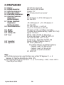
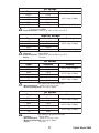
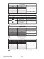
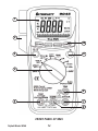
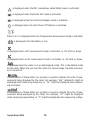
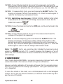
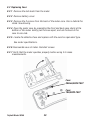
TRIPLETT
Model
9045
True RMS
Digital Multimeter
Instruction Manual
CONTENTS
PAGE
1. Introduction
2. Safety Rules and Warnings
3. International Symbols
4. Product Features
5. Specifications
6. Front Panel and LCD Display
7. Measurement Procedures
DC & AC Voltage
DC & AC Current
Resistance
Continuity
Diode
Capacitance
Temperature
Frequency & Duty Cycle
8. Maintenance
9. Accessories
10. Warranty
2
3-8
8
9
10 - 13
14 - 17
17 - 20
20 - 21
22 - 24
24
24
25
26
27
27
28 - 30
31
32
1: INTRODUCTION
The Triplett Model 9045 is a 6000 count, autoranging, True RMS, handheld Digital Multimeter with a 61 segment bargraph in its backlit Liquid Crystal Display. At
its core is an LSI (Large Scale Integration) integrated circuit which uses dual
slope A/D conversion for stability and accuracy. The meter can measure AC and
DC Voltage and Current, Resistance, Diode voltage drop, Continuity, Capacitance,
Temperature, and Frequency. Defeatable Auto Power Off, Data Hold, REL, and
Min-Max Memory features enhance convenience, and Overload protection makes
the meter resistant to damage from accidental overloads. The overmolded case
adds ruggedness and presents a stylish appearance.
WARNING!!!
This meter is NOT to be used to measure power circuitry exceeding
CATEGORY III / 600 Volts (CAT III / 600 Volts). Using this meter on such
circuitry could result in damage to the meter and user injury.
Triplett Model 9045
2
84-866 Rev A
1/06
2: SAFETY RULES & WARNINGS
2.1 Read all instructions in this manual before using this meter. Failure to do so
may result in damage to the meter or injury to the user.
2.2 Prior to using the meter in any situation which could result in injury to the
user, in order to verify that the meter is functional and producing a valid
reading, test the meter on a circuit(s) known to have potentials equivalent to
the potential that is to be measured. For example, before using the meter to
determine if an AC power line is energized with 120VAC, test the meter on a
line known to be energized with 120VAC. Failure to do so may result in
damage to the meter or injury to the user.
2.3 Do not use this meter with its case open, or with parts removed. Doing so
may damage the meter and/or injure the user.
2.4 When using this meter in schools and workshops, responsible teachers or
skilled personnel must control the usage of this meter. Failure to observe this
precaution may result in damage to the meter or injury to the user.
2.5 Follow the recommendations of any Trade Organizations or Regulatory
Agencies whose scope encompasses the use of this meter. Failure to do so
may result in damage to the meter or injury to the user.
2.6 Do not open this meter for maintenance without first disconnecting the test
leads from all external circuitry. Failure to observe this precaution may result
in damage to the meter or injury to the user.
2.7 Repairs and maintenance must only be carried out by qualified service
personnel or qualified electricians / technicians who know the dangers of,
and the safety rules applicable to this type of equipment. Failure to observe
this precaution may result in damage to the meter or injury to the user.
2.8 Always set the meter to the appropriate range or mode before connecting it
to the circuitry to be tested. Failure to observe this precaution may result in
damage to the meter or injury to the user.
2.9 Check the condition of the test leads before making a measurement. Do not
use the test leads if there is damaged insulation or exposed metal. Failure
to observe this precaution may result in damage to the meter or injury to
the user.
3
Triplett Model 9045
2.10 Make sure test leads are properly inserted and seated in the meter’s input
jacks. A loose test lead may cause the user to believe that no hazard exists,
when in fact, dangerous voltages or currents may be present. Failure to
observe this precaution may result in damage to the meter or injury to
the user.
2.11 Do not touch the tips of the test leads when making a measurement. Do not
touch live circuitry when making a measurement. Failure to observe this
precaution may result in damage to the meter or injury to the user.
2.12 Before using the meter, examine both the meter and the test leads for
damage. Do not use the meter if damage (damaged insulation, exposed
metal, cracked case, burnt smell, etc.) is evident. Failure to observe this
precaution may result in damage to the meter or injury to the user.
2.13 Insert the test leads in the jacks specified in the instructions for performing
particular tests. Inserting the test leads in incorrect jacks can damage the
meter and/or injure the user.
2.14 Do not exceed the maximum voltage or current limitations of the meter
(see product specifications). Doing so may damage the meter and/or
injure the user.
2.15 Do not apply voltage or current to the input of the meter when it is set to any
of the Ohms Ω ranges. Doing so may damage the meter and/or injure
the user.
2.16 Do not apply voltage or current to the input of the meter when it is set to the
Diode Test
or Continuity Beeper
the meter and/or injure the user.
modes. Doing so may damage
2.17 Do not attempt to measure a voltage source with the test leads plugged into
the meter’s uA/mA or 10A jacks. Doing so may damage the meter and/or
injure the user.
2.18 Do not rotate the Function switch with the test leads connected to the
circuitry to be tested. Doing so may damage the meter or the circuitry,
and/or injure the user.
2.19 Replace fuses only with exact or equivalent fuses. Do not “bridge” fuses out
of circuit. Failure to observe this precaution may result in damage to the
meter or injury to the user.
Triplett Model 9045
4
2.20 Do not apply voltages to the input of the meter which are elevated above the
earth ground potential by more than 600V AC/DC. Doing so may damage
the meter and/or injure the user.
2.21 Do not continue to use meter when the “low battery” symbol
is
displayed. The displayed reading may be in error and lead the user to
believe that no hazard exists, when in fact, dangerous voltages or currents
may be present. Failure to observe this precaution may result in damage to
the meter or injury to the user.
2.22 Use caution when working with voltages above 25 volts AC or 35 volts DC.
Such voltages may cause a life threatening electrical shock.
2.23 This meter is not for use by children. Failure to observe this precaution may
result in damage to the meter or injury to the user.
2.24 Do not use this meter to make measurements in adverse environments such
as rain, snow, fog, or locations with steam, explosive gases or dusts.
Doing so may damage the meter and/or injure the user.
2.25 Do not use meter in condensing atmospheres. That is, do not use meter in
conditions where ambient temperature and humidity could cause condensation of water inside of meter. Doing so may cause injury to the user.
2.26 Do not use the meter if either the meter or the test leads are wet, either from
exposure to the weather, or after cleaning the case of the meter. Doing so
may cause injury to the user.
2.27 Do not attempt immediate use of the meter when bringing it from a cold
environment to a warm environment. Condensation of water, inside and
outside of the meter, may produce dangerous measuring conditions. Allow
the meter to warm to room temperature before using. Failure to observe
this precaution may result in damage to the meter or injury to the user.
2.28 Do not modify the meter. Changing the design may make the meter unsafe
and may result in injury to the user.
2.29 Use caution when attempting to evaluate if a dangerous voltage is present.
The meter will not read AC voltage if it is set to DC, nor will it read DC if it
is set to AC. For example, if the meter is set to measure DC Volts, it will not
measure a dangerous AC voltage, even if the probes are inserted into a
household AC wall outlet.
5
Triplett Model 9045
2.30 Do not touch the metallic portion of one test lead if the other test lead is
connected to a live circuit. The current from the live circuit may pass
through the meter and appear on the unconnected test lead. Failure to
observe this warning may result in user injury.
2.31 Do not attempt to use meter when no display is present on LCD. Doing so
may damage the meter and/or injure the user.
2.32 Use caution when measuring circuits containing capacitors. Capacitors can
store dangerous or lethal levels of electricity, even when the circuitry which
they are in has been disconnected from its power source. Some capacitors
could source enough energy to damage the meter and/or injure the user.
2.33 Use caution when using this meter to measure voltages or currents in
industrial applications where High Energy circuitry is used. High Energy
circuitry is usually regarded as any circuitry capable of supplying over 4000
watts to a load before a safety device (like a fuse) interrupts the circuit.
2.34 Do not use this meter to measure current in circuits whose open circuit
voltage exceeds the voltage range of the meters’ fuses. Failure to observe
this precaution may result in damage to the meter or injury to the user.
2.35 When you use the meter to check a high-voltage circuit, do not try to
connect both test leads at once. Instead, clip one probe to the neutral
or ground lead of the circuit (usually a bare, green, or white wire in AC
wiring circuits) using the insulated slip-on Alligator Clips. Then probe
for voltages with the other test lead. This helps prevent you from
accidentally touching a hot wire, since you need to concentrate on only
one test lead. Failure to observe this precaution may result in damage to
the meter or injury to the user.
2.36 If there is any doubt about the condition of the meter (i.e. safe vs unsafe),
remove the meter from service and secure it in a location that will prevent
its unintentional use. Failure to observe this precaution may result in
damage to the meter or injury to the user.
2.37 Do not use the meter if it does not appear to work correctly on all ranges and
in all modes. Failure to observe this precaution may result in damage to
the meter or injury to the user.
2.38 Do not use the meter if it has undergone long-term storage under unfavorable conditions. Failure to observe this precaution may result in damage to
the meter or injury to the user.
Triplett Model 9045
6
2.39 Do not use the meter if it may have been damaged in transport. Failure to
observe this precaution may result in damage to the meter or injury to
the user.
2.40 Always connect one of the meter’s alligator clips to the low side of a power
circuit first. Never clamp onto a hot wire first, (usually red, black, or blue
in AC wiring circuits.) If you clamp onto a hot wire first, and touch the
other probe, you could receive a shock. Failure to observe this precaution
may result in damage to the meter or injury to the user.
2.41 To avoid damage to the meter and possible user injury, disconnect test leads
from test points before changing the function/range. Failure to observe this
precaution may result in damage to the meter or injury to the user.
2.42 Avoid usage near strong magnetic fields (magnets, loudspeakers,
transformers, motors, coils, relays, contactors, electromagnets, etc.).
The meter may display readings that are in error, causing the user to
misinterpret the hazards present. For example, the meter may indicate a
low voltage when high voltages are actually present. Failure to observe this
precaution may result in damage to the meter or injury to the user.
2.43 Avoid usage near strong electrostatic fields (high voltage power lines,
televisions, computer monitors, etc.). The meter may display readings that
are in error, causing the user to misinterpret the hazards present. For
example, the meter may indicate a low voltage when high voltages are
actually present. Failure to observe this precaution may result in damage
to the meter or injury to the user.
2.44 Avoid usage near strong RF fields (radio or television transmitters, walkie
talkies, cellular phones, etc.). The meter may display readings that are in
error, causing the user to misinterpret the hazards present. For example, the
meter may indicate a low voltage when high voltages are actually present.
Failure to observe this precaution may result in damage to the meter or
injury to the user.
2.45 Remove the battery when the meter may be left unused for longer than 1
month. Chemical leakage from the battery could damage the meter,
leading to user injury.
2.46 Do not use the meter if there is evidence of chemical leakage from the
battery. Leakage could damage meter and lead to injury of user.
7
Triplett Model 9045
2.47 Observe whether HOLD function is activated. The meter may not show
the presence of dangerous potentials when HOLD is activated. For
example, if HOLD is applied when the meter is reading zero, and 120VAC
is subsequently applied, the meter will continue to read zero. Failure to
observe this precaution may result in damage to the meter or injury to the
user.
2.48 Do not attempt to test charged capacitors. Only discharged capacitors
may be tested. If you wish to test a capacitor, discharge it using an
approved method before connecting it to the meter. Caution: Some
capacitors can store dangerous lethal charges. Discharging these
capacitors can be dangerous unless an approved method is used. Failure
to observe this precaution may result in damage to the meter or injury
to the user.
2.49 Do not use the thermocouple to measure the temperature of objects that are
electrically “live”. Failure to observe this precaution may result in damage
to the meter or injury to the user.
3: INTERNATIONAL SYMBOLS
The following International Symbols may be used in this manual and on the case
of the meter to identify, caution, or warn the user of important product limitations
or important operational procedures that must be followed to ensure safe usage
of the product.
_ +
Low Battery
Ground
See Instruction Manual
AC
DC
Fuse
Double Insulated
Beeper
Diode
AC or DC
Dangerous Voltages
Capacitance
Triplett Model 9045
8
4: PRODUCT FEATURES
4.1
4.2
4.3
4.4
4.5
4.6
4.7
4.8
4.9
4.10
4.11
4.12
4.13
4.14
4.15
4.16
4.17
4.18
4.19
4.20
4.21
4.22
4.23
4.24
True RMS AC Measurements to 750 Volts
6000 Count Resolution
61 Segment Bargraph
Blue Backlit Display
Auto / Manual Ranging
DC Voltage Ranges to 1000 Volts
AC/DC Current ranges to 10 Amps
Resistance Ranges to 60 MΩ
Temperature Measurements (F or C display)
Capacitance Measurements to 4000uF
Frequency Measurements (60Hz displays as “60.00”)
Diode Test indicates true voltage across diode
Continuity Beeper
Data HOLD button
Defeatable Auto Power Off
RELative mode
Min / Max Memory mode
Fused Current Ranges
Overload protection
Double Insulated Shock Resistant Overmolded Case with Built-in Stand
Safety Designed to Comply with IEC 1010-1 (CE)
CAT III / 600V and CAT II / 1000V Rated
3 Year Warranty
Includes: Safety Test Leads with Screw-On Alligator Clips,
Thermocouple Probe and Adaptor, 9 Volt Battery
9
Triplett Model 9045
5: SPECIFICATIONS
5.1
5.2
5.3
5.4
5.5
5.6
Display:
Display Resolution:
Overrange Indication:
Measurement Rate:
Low Battery Annunciator:
Operating Conditions:
Temperature:
Relative Humidity:
5.7 Storage Conditions:
Temperature:
Relative Humidity:
5.8 Case Dimensions:
5.9 Weight:
5.10 Battery:
5.11 Battery Life:
5.12 Fuse:
5.13 Insulation:
5.14 Approvals:
0.8" (20.3mm) high LCD
6000 counts, 0000 to 5999
Displays “OL”
2 to 3 measurements per second
_ +
0 to 40 degrees C (32 to 104 degrees F)
less than 80%
-20 to 60 degrees C (-4 to 140 degrees F)
less than 90%
177 x 93 x 39 mm, (L x W x H)
7.0 x 3.7 x 1.5 inches (L x W x H)
300 grams, 0.7 lbs. (w/ battery, w/o leads)
1 standard 9 volt alkaline battery (Triplett PN: 37-48)
approx. 100 hours
800mA / 600 volt FAST, 5 x 20mm fuse,
for uA or mA ranges. Triplett PN: 3207-131
10A / 600 volt FAST, 1/4” x 1” fuse,
for 10A range. Triplett PN: PN 3207-128
Double Insulated (Protection Class II)
IEC 1010-1 (EN61010-1)
Overvoltage Category (Installation Category)
Category I and II to 1000 volts DC
Category I and II to 750 volts AC
Category III to 600 volts AC/DC
CE: EMC, LVD
Note:
a) The following accuracy specifications are valid at 23 degrees C, +/- 5
degrees C, Relative Humidity less than 75%
b) The specifications are in the form “ +/- (x % of reading + LSD)” where LSD is
“Least Significant Digit”.
Triplett Model 9045
10
DC Voltage
Range
Resolution
600mV
6V
60V
600V
1000V
0.1mV
1mV
10mV
100mV
1V
Accuracy
±(0.5% rdg + 5 digits)
±(0.8% rdg + 5 digits)
Input Impedance: All ranges are 10MΩ except 600mV range
is greater than 1000MΩ
Overload Protection: 1000V DC or 750V AC RMS Sine (CAT II)
TRMS AC Voltage
Range
Resolution
6V
60V
600V
750V
1mV
10mV
100mV
1V
Accuracy
±(0.8% rdg + 5 digits)
±(1.2% rdg + 5 digits)
Input Impedance:
All ranges are 10MΩ
Frequency:
50Hz to 400Hz
Overload Protection: 1000V DC or 750V AC RMS Sine (CAT II)
Display:
True RMS
DC Current
Range
Resolution
600µA
6000µA
60mA
600mA
6A
10A
0.1µA
1µA
10µA
0.1mA
1mA
10mA
Accuracy
±(2.0% rdg + 5 digits)
±(1.5% rdg + 5 digits)
±(2.0% rdg + 5 digits)
Overload Protection: 800mA / 600V fuse (below 6A range)
10A / 600Fuse for 6A and 10A Ranges
Max. Current Input: 10A for 15 sec each 15 min.
Measuring Voltage Drop: Full range is 300mV.
AC Current
Range
Resolution
600µA
6000µA
60mA
600mA
6A
10A
0.1µA
1µA
10µA
0.1mA
1mA
10mA
Accuracy
±(2.5% rdg + 5 digits)
±(2.0% rdg + 5 digits)
±(2.5% rdg + 5 digits)
Overload Protection: 800mA / 600V fuse (below 6A range)
10A / 600V fuse for 6A and 10A ranges
Frequency:
50Hz to 400Hz
Max. Current Input: 10A for 15 sec each 15 min.
Measuring Voltage Drop: Full range is 300mV.
Display:
True RMS
11
Triplett Model 9045
Resistance
Range
Resolution
600Ω
6KΩ
60KΩ
600KΩ
6MΩ
60MΩ
0.1Ω
1Ω
10Ω
100Ω
1KΩ
10KΩ
Accuracy
±(1.0% rdg + 5 digits)
±(2.0% rdg + 5 digits)
Overload Protection: All ranges 600V DC or AC RMS for less than 10 sec. (CAT I)
Diode Test and Continuity Beeper
Range
Resolution
Accuracy
Displays actual diode
voltage in Volts
Beeper sounds if
Continuity Resistance
is less than
approx. 120 Ohms
Forward DC currrent about 1mA
Open circuit volage about 2.8V
Open circuit volage about 2.8V
Overload Protection: All ranges 600V DC or AC RMS for less than 10 sec. (CAT I)
Capacitance
Range
Resolution
Accuracy
40nF *
10pF
±(5.0% rdg + 10 LSD)
400nF *
100pF
4µF
1nF
±(3.0% rdg + 5 LSD)
40µF
10nF
400µF
100nF
±(20.0% rdg + 20 LSD)
4000µF
1µF
Overload Protection: 600V DC or AC RMS for 30 sec. max (CAT I)
REL residual zero reading
* Not accurate below 10nF.
Frequency
Range
Resolution
Accuracy
9.999Hz
0.001Hz
99.99Hz
0.01Hz
999.9Hz
0.1Hz
9.999KHz
0.001KHz
±(0.1% rdg + 5 LSD)
99.99KHz
0.01KHz
999.9KHz
0.1KHz
9.999MHz
0.001MHz
Overload Protection: 600V DC or AC RMS (CAT I)
Input Sensitivity: 1.5V RMS below 100KHz, 5V RMS above 100KHz
Triplett Model 9045
12
Temperature
Range
Resolution
Accuracy
-58° F to 392° F
±(0.75% rdg + 5 digits)
32° F to 104° F
2 degree Fahrenheit
±5° F
392° F to 752° F
±(1.5% rdg + 5 digits)
±(0.75% rdg + 3 digits)
-50° C to 200° C
0° C to 40° C
1 degree Centigrade
±3° C
200° C to 400° C
±(1.5% rdg + 3 digits)
Overload Protection: 600V DC or AC RMS for 30 sec. (CAT I)
The provided thermocouple is only rated up to 300°F. Above this temperature,
the thermocouple will function, but the lead wire may melt or char.
Duty Cycle
Range
Resolution
Accuracy
0.1 to 99.9%
0.1%
±(2.0% rdg + 5 digits)
Overload Protection: 600V DC or AC RMS (CAT I)
13
Triplett Model 9045
1
2
10
3
9
4
8
5
7
6
FRONT PANEL OF 9045
Triplett Model 9045
14
6: 9045 FRONT PANEL AND LCD DISPLAY
1)
2)
3)
4)
5)
LCD Display
Test Probe Holders
Data HOLD and Backlight Button
Rotary FUNCTION Selector Switch
Input Jack for Voltage, Resistance, Capacitance,
Temperature, Frequency, Diode Test, and Continuity
6) COMmon Input Jack for all measurements and tests
7) µA/mA Input Jack for 600uA to 600mA ranges
8) 10A Input Jack for 6A and 10A ranges
9) RELative button
10) FUNCTION pushbuttons, SELECT, Hz/DUTY, MAX/MIN, and RANGE
The numeric digits readout the measured quantity for all modes and functions.
The minus sign appears if the measured quantity is negative with respect to the
meter’s COM jack, or if the meter is REL’ed and the quantity is less than the REL
value. Only one decimal point is displayed at a time, its position indicating the
range that the meter is set to.
Either MAX or MIN is displayed when the MAX/MIN mode is activated.
is displayed when the HOLD mode is activated.
15
Triplett Model 9045
is displayed when the REL (sometimes called Delta) mode is activated.
is displayed when the Diode Test mode is activated.
is displayed when the Continuity Beeper mode is activated.
is displayed when the Auto Power Off feature is activated.
Either C or F is displayed when the Temperature measurement mode is activated.
is displayed when the battery is low.
is displayed when a DC measurement mode is activated, i.e. DC Volts or Amps.
is displayed when an AC measurement mode is activated, i.e. AC Volts or Amps.
is displayed when the meter is in an Autoranging mode. This is the default mode
for the meter. When the user sets the meter to a manual range, the Auto annunciator is turned off.
A combination of these letters (or symbols) is used to indicate the units of measurement being displayed by the meter. For example, “kHz” (kiloHertz) might be
displayed when measuring frequency, or “ Ω “ might be displayed when measuring resistance.
A combination of these letters (or symbols) is used to indicate the units of measurement being displayed by the meter. For example, “nF” might be displayed
when measuring capacitance, or “V” might be displayed when measuring voltage.
Triplett Model 9045
16
The bargraph visually indicates how the input quantity compares with the measurement range of the meter. For example, if the meter is set to the 6 Volt DC
range, and 3 volts is applied to the meter’s input, the bargraph would extend from
0 to 30, half the length of the bargraph, indicating that the measured quantity is 1/
2 of the range setting. This feature is often used for “nulling” or “peaking” adjustments, which are easier to visualize on the bargraph, rather than examining the
numeric digital reading.
7: MEASUREMENT PROCEDURES
WARNING!!!
Do not use the meter when the low battery annunciator
is displayed.
This may cause the meter to produce inaccurate readings,
and lead the user to believe that no hazard exists, when,
in fact, dangerous voltages or currents are present.
7.1 Pushbuttons and their Functions
7.1.1 Using the HOLD feature
The 9045 incorporates a convenient HOLD feature. This feature “freezes”
button is quickly pressed and
the reading in the LCD when the
released. To release the HOLD, press the button again.
Note: The
annunciator appears in the LCD when HOLD is activated.
WARNING!!!
The meter may not show the presence of dangerous potentials when HOLD is
activated. For example, if HOLD is applied when the meter is reading zero,
and 120VAC is subsequently applied, the meter will continue to read zero.
Failure to observe this precaution may result in damage to the meter
or injury to the user.
17
Triplett Model 9045
7.1.2 Auto Power Off
The 9045 has Defeatable Auto Power Off. This power saving feature automatically turns the meter off 15 to 20 minutes after the last button press
or switch actuation.
The
annunciator appears on the LCD when the feature is activated. To
defeat the Auto Power Off, and keep the meter running continuously, hold
down the SELECT pushbutton while turning the meter on. The annunciator
will not appear in the display.
7.1.3 The SELECT Button
The 9045 has several test functions available on one position of the rotary
FUNCTION switch. To access the different functions, the SELECT button is
momentarily pressed, repeatedly if necessary, until the desired function is
obtained. In the Voltage and Current measurement modes, the SELECT
button allows either AC or DC signals to be measured. In the Temperature
measurement mode, the SELECT button allows the meter to display its
measurement in either Centigrade or Fahrenheit.
On the
position of the rotary FUNCTION switch, use the
SELECT button to choose the desired measurement mode.
To determine the measurement mode, observe the LCD display annunciators while the SELECT button is being pressed.
7.1.4 Using the Backlite
The LCD incorporates a blue LED backlite that aids the user when using the
meter in poorly lit areas. The same button that activates the HOLD is used to
activate the Backlite. To turn on the Backlite, the
button is pressed
and held for 2 seconds or longer. Because the Backlite consumes so much
power (it uses more power than all of the other electronics in the meter), it
only stays on briefly (about 8 to 10 seconds) and automatically turns itself
off. To turn the Backlite off manually, before it goes off automatically, press
and hold the button again until the Backlite turns off.
Since the HOLD feature and Backlite feature share the same button, there is
some interaction in their operation. A few presses of the button will reveal
how to use the button effectively.
Triplett Model 9045
18
7.1.5 REL Mode
Press the
(REL) button to make subsequent readings RELative to the
present reading, or to “zero out” any zero error. The button is usually used
to zero out a residual resistance reading on the 600Ω range, or the residual
stray capacitance reading on the 40nF range. This button does not work in
all ranges or modes. For example, it doesn’t work in the Frequency, Diode
Test, or Continuity modes.
7.1.6 MAX / MIN Mode
The 9045 contains a convenient memory that remembers the Maximum and
Minimum values measured by the meter. The feature can be used for a few
minutes or several hours to memorize the Maximum and Minimum values
measured by the meter.
To activate the feature, press the MAX / MIN button when the meter is in the
desired range. The MAX annunciator will appear in the display, and the Auto
Ranging and Auto Power Off features will deactivate. When the MAX annunciator is displayed, the meter is showing the maximum or “peak” value in its
memory. Another press of the MAX / MIN button will turn off the MAX annunciator and turn on the MIN annunciator. Now the minimum or “valley”
value in the meter’s memory is being displayed. Subsequent presses of the
button will toggle the meter’s display between the MAX and MIN display
modes.
Notes:
This feature does not work in all measurement modes. For example, it does not
work in the Frequency, Continuity, Diode Test, and Capacitance modes.
When using MAX / MIN, the meter is in a manual ranging mode… i.e. the meter
will not autorange if the signal being measured is above or below the range selected when the MAX / MIN button was pressed.
To return to the normal measurement mode, press and hold the MAX / MIN button
until the meter beeps and the MAX and MIN annunciators turn off.
7.1.7 RANGE Selection
After a measurement mode is chosen by using the rotary FUNCTION switch
and the SELECT button (if necessary), the RANGE may be chosen manually
or automatically. That is, the user has the option to allow the meter to select
its measurement range, or the user may manually select the measurement
range.
To allow the meter to select the range, the user need do nothing . . . its
automatic. The Auto annunciator informs the user that the meter will
choose the appropriate measurement range.
19
Triplett Model 9045
To select the range manually, press the RANGE button. The first press of the
button will turn off the Auto annunciator, and the meter will be in the range
the meter was on when the Auto annunciator was on. Subsequent presses
of the button will manually select additional ranges. The actual range
selected can be determined by observing the decimal points and range
annunciators on the LCD display.
Notes:
The ranges are arranged in sequence, starting at the lowest range first, and
incrementing to the next higher range with each press of the RANGE button. When
on the highest range, the next RANGE button press will set the meter to the lowest
range, and each subsequent press will increment the meter to the next higher
range.
To exit the manual ranging mode, press and hold the RANGE button until the
meter beeps and the Auto annunciator in the display comes on.
Some modes do not allow the ranges to be selected manually. For example, the
Capacitance and Frequency ranges are autoranging only.
7.1.8 Hz / Duty Measurement
Hz (Frequency) and Duty (Duty Cycle) can be measured in two different ways
on the 9045. The method chosen depends on the type of measurement being made by the user. The Hz / Duty button is used in both methods. See the
following sections for specific information on performing the measurements.
7.2 Rotary FUNCTION Selector Switch
7.2.1 DC Voltage Measurement:
WARNING!!!
Do not rotate the FUNCTION switch with an input applied to the meter.
If the input voltage is higher than 1000V DC (CAT II),
or 600V DC (CAT III), do not attempt to measure!
Use Caution when measuring voltages above 50V DC.
7.2.1.1 Connect the black test lead to the COM jack and the red test lead to the
jack.
7.2.1.2 Set the rotary FUNCTION switch to the
Triplett Model 9045
20
position.
7.2.1.3 Connect the test probes to circuit being measured. The LCD will display
the DC voltage. Note the position of the decimal point and the units annunciator when reading the voltage.
7.2.1.4 If the display indicates overrange, i.e. “OL”, disconnect the test probes
from the circuit immediately! The voltage exceeds the measurement range
of the 9045.
7.2.1.5 To set the range manually, press the RANGE button, repeatedly if necessary, to select the desired range. Observe the position of the decimal point
and the annunciators to identify the selected range.
7.2.2 AC Voltage Measurement
WARNING!!!
Do not rotate the FUNCTION switch with an input applied to the meter.
If the input voltage is higher than 750VAC (CAT II),
or 600VAC (CAT III), do not attempt to measure!
Use Caution when measuring voltages above 30V AC.
7.2.2.1 Connect the black test lead to the COM jack and the red test lead to the
jack.
7.2.2.2 Set the rotary FUNCTION switch to the
position.
7.2.2.3 Connect the test probes to circuit being measured. The LCD will display
the AC voltage. Note the position of the decimal point and the units annunciator when reading the voltage.
7.2.2.4 If the display indicates overrange, i.e. “OL”, disconnect the test probes
from the circuit immediately! The voltage exceeds the measurement range
of the 9045.
7.2.2.5 To set the range manually, press the RANGE button, repeatedly if necessary, to select the desired range. Observe the position of the decimal point
and the annunciators to identify the selected range.
21
Triplett Model 9045
7.2.3 DC Current Measurement
WARNING!!!
If the magnitude of the current to be measured is unknown, always start by
setting the meter to the highest range, and then to lower ranges,
until a satisfactory reading is obtained.
Do not rotate the FUNCTION switch with the input applied to the meter.
If the input current is higher than 10A, do not attempt to measure!
Use caution when measuring current in a circuit with voltages
above 50 VDC. Do not use meter to measure current in circuits
whose voltage exceeds the voltage rating of the meters’ fuses.
7.2.3.1 Connect the black test lead to the COM jack. Connect the red test lead to
the 10A jack unless it is known that the input current is less than 600mA or
6000uA. If the current is less than 6000uA or 600mA, connect the red test
lead to the uA/mA jack.
7.2.3.2 If the red test lead is inserted into the 10A jack, set the FUNCTION switch
to the 10A position. Connect test leads in series with circuit to be measured.
Read the value of the current on the LCD display.
7.2.3.3 If the red test lead is inserted into the uA/mA jack, set the FUNCTION
switch to the uA or mA position. Connect test leads in series with circuit to
be measured. Read the value of the current on the LCD.
7.2.3.4 If the display indicates overrange, i.e. “OL”, disconnect the test probes
from the circuit and reconnect the red test lead to the 10A jack. Set the
FUNCTION switch to the 10A position, and reconnect the test leads to the
circuit. Read the value from the LCD. If the input current exceeds the measurement capability of the meter, as evidenced by a display of over 10 amps,
or an overrange display, it should not be measured.
7.2.3.5 If the displayed value is less than “600” (decimal point not shown), a
more accurate reading may be obtained by setting the FUNCTION switch to a
lower range and using a different jack. Disconnect the probes from the
circuit and rotate the FUNCTION switch to the next lower position. Reconnect the test probes to the circuit and observe the reading on the LCD dis
play. If the FUNCTION switch is already on the lowest position (i.e. uA), no
greater measurement resolution can be obtained.
7.2.3.6 To set the range manually, press the RANGE button, repeatedly if necessary, to select the desired range. Observe the position of the decimal point
and the annunciators to identify the selected range.
Triplett Model 9045
22
7.2.4 AC Current Measurement:
WARNING!!!
If the magnitude of the current to be measured is unknown, always start by
setting the meter to the highest range, and then to lower ranges,
until a satisfactory reading is obtained.
Do not rotate the FUNCTION switch with the input applied to the meter.
If the input current is higher than 10A, do not attempt to measure!
Use caution when measuring current in a circuit with voltages
above 30 VAC. Do not use meter to measure current in circuits
whose voltage exceeds the voltage rating of the meters’ fuses.
7.2.4.1 Connect the black test lead to the COM jack. Connect the red test lead to
the 10A jack unless it is known that the input current is less than 600mA or
6000uA. If the current is less than 6000uA or 600mA, connect the red test
lead to the uA/mA jack.
7.2.4.2 If the red test lead is inserted into the 10A jack, set the FUNCTION switch
to the 10 A position. Press the SELECT button so that the AC annunciator is
on. Connect test leads in series with circuit to be measured. Read the value
of the current on the LCD display.
7.2.4.3 If the red test lead is inserted into the uA/mA jack, set the FUNCTION
switch to the uA or mA position. Press the SELECT button so that the AC
annunciator is on. Connect test leads in series with circuit to be measured.
Read the value of the current on the LCD.
7.2.4.4 If the display indicates overrange, i.e. “OL”, disconnect the test probes
from the circuit and reconnect the red test lead to the 10A jack. Set the
FUNCTION switch to the 10A position, and reconnect the test leads to the
circuit. Read the value from the LCD. If the input current exceeds the measurement capability of the meter, as evidenced by a display of over 10 amps,
or an overrange display, it should not be measured.
7.2.4.5 If the displayed value is less than “600” (decimal point not shown), a
more accurate reading may be obtained by setting the FUNCTION switch to a
lower range and using a different jack. Disconnect the probes from the
circuit and rotate the FUNCTION switch to the next lower position. Reconnect the test probes to the circuit and observe the reading on the LCD
display. If the FUNCTION switch is already on the lowest position (i.e. uA),
no greater measurement resolution can be obtained.
23
Triplett Model 9045
7.2.4.6 To set the range manually, press the RANGE button, repeatedly if necessary, to select the desired range. Observe the position of the decimal point
and the annunciators to identify the selected range.
7.2.5 Resistance Measurement
WARNING!!!
Do not apply voltage or current to the meter when the
FUNCTION switch is set to
7.2.5.1 Connect the black test lead to the COM jack, and the red test lead to the
jack.
7.2.5.2 Set the FUNCTION switch to the
position. The LCD display
will indicate overrange (i.e. “OL”).
7.2.5.3 Connect the test leads to the device or circuit being measured. Observe
correct polarity if appropriate. Read the value of the resistance on the LCD
display.
7.2.5.4 To set the range manually, press the RANGE button, repeatedly if necessary, to select the desired range. Observe the position of the decimal point
and the annunciators to identify the selected range.
Notes:
a) The 6M, and 60M ranges may require several seconds to stabilize.
b) To obtain the most accurate reading on the 60Ω range, short the test leads
together and press the REL button to null out any zero error. Unshort the leads
and proceed with measurements.
7.2.6 Continuity Beeper
WARNING!!!
Do not apply voltage or current to the meter when the
FUNCTION switch is set to
Triplett Model 9045
24
7.2.6.1 Connect the black test lead to the COM jack, and the red test lead to the
jack.
7.2.6.2 Set the FUNCTION switch to the
position. Press the SELECT
button, repeatedly if necessary, to select the Continuity Beeper mode. The
annunciator will turn on when the Continuity Beeper mode is selected.
The LCD display will indicate overrange (i.e. “OL”).
7.2.6.3 Connect the test leads to the device or circuit being tested. If the continuity of the tested circuit is less than about 120 Ohms, the beeper will sound
and the approximate resistance will be displayed on the LCD.
7.2.7 Diode Test
WARNING!!!
Do not apply voltage or current to the meter when the
FUNCTION switch is set to
7.2.7.1 Connect the black test lead to the COM jack, and the red test lead to the
jack.
7.2.7.2 Set the FUNCTION switch to the position. Press the SELECT button,
repeatedly if necessary, to select the Diode Test mode. The
annunciator will turn on when the Diode Test mode is selected.
The LCD display will indicate overrange (i.e. “OL”).
7.2.7.3 Connect the test leads to the device or circuit being tested, observing the
appropriate polarity. To test a simple diode, connect the red test probe to
the Anode of the diode and the black test lead to the Cathode (“banded”
end) of the diode. The LCD will indicate the voltage drop of the diode.
Reverse the connections of the test probes to the diode. The LCD should
indicate overrange (“OL”). If the display reads “0.000 v” when the leads are
connected in either direction to a standard silicon diode, the diode is
probably shorted.
Note: The reading displayed on the LCD is an accurate indication of the voltage
drop of the device or circuit being measured.
25
Triplett Model 9045
7.2.8 Measuring Capacitance
WARNING!!!
Do not connect a charged capacitor to the meter.
Doing so may damage the meter or injure the user.
Do not apply voltage or current to the meter when the
FUNCTION switch is set to
7.2.8.1 Connect the black test lead to the COM jack, and the red test lead to the
jack.
7.2.8.2 Set the FUNCTION switch to the
position. Press the SELECT
button, repeatedly if necessary, to select the Capacitance Test mode. The nF
annunciator will turn on when the Capacitance Test mode is selected.
7.2.8.3 Before testing capacitor, be certain it is discharged and disconnected
from any other circuitry that may cause an erroneous measurement.
WARNING!!!
Use an approved method to discharge the capacitor. Some capacitors can
hold a dangerous charge, and discharging them inappropriately can be
hazardous to the user.
7.2.8.4 When measuring values less than 40nF, consider using the REL feature
to “null out” any residual reading. Residual readings of 100 to 150 counts
(1.00 to 1.50nF) are typical. Refer to section 7.1.5.
7.2.8.5 Connect the test leads to the capacitor to be tested. Read the measured
value from the LCD display.
Note: Capacitors larger than 100uf will take some time to measure. 1000uf will
take between 10 and 20 seconds to measure.
If the display indicates OL, the capacitor is larger than the meter will measure, or
it is leaky or shorted.
Measurements on capacitors with values less than 10nF are not accurate.
Triplett Model 9045
26
7.2.9 Measuring Temperature
WARNING!!!
Do not attempt to measure the temperature of any surface that is electrically
“live”. Failure to observe this precaution may result in injury to the user.
Do not apply voltage or current to the meter when the
FUNCTION switch is set to
7.2.9.1 Remove the test leads from the input jacks of the meter.
7.2.9.2 Set the FUNCTION switch to the
position. Using the SELECT
button, select the desired units of measurement (C or F). Plug the provided
thermocouple adaptor into the COM and
jacks. The nega-
tive side of the adapter (marked “-”) plugs into the COM jack. Plug the provided thermocouple lead into the adaptor, observing correct polarity (plus to
plus, minus to minus).
7.2.9.3 Read the temperature on LCD display. Use the SELECT button to change
the units of measure ( C or F).
7.2.10 Measuring Frequency and Duty Cycle
Frequency and Duty Cycle can be measured in several different ways on the
Triplett 9045. The method chosen depends on the type of measurement
being made. For wideband low level measurements, such as measurements
in electronic circuitry, the
position on the FUNCTION switch works
best. For measurement at higher voltages, and lower frequencies (like 120
VAC /60Hz), the
mode works best.
7.2.10.1 ‘Wideband Low Level Measurements (several volts peak to peak up to
10MHz) are made by setting the FUNCTION switch to the
position.
7.2.10.2 Connect the black test lead to the COM jack, and the red test lead to the
jack.
27
Triplett Model 9045
7.2.10.3 Connect the test leads to the circuit to be measured, and read the
frequency on the LCD display. Observe the position of the decimal point and
the annunciator to determine the units of measure (i.e. Hz, kHz, MHz, etc)
7.2.10.4 To measure Duty Cycle, press and release the Hz/DUTY button. The
display will change to a Duty Cycle readout in %. Press the button again to
return to the Frequency measurement mode.
7.2.10.5 High Voltage Low Frequency (120VAC, 220VAC, 480VAC, 50Hz, 60Hz)
measurements are made in the AC Voltage measurement mode. Set the
FUNCTION switch to
7.2.10.6 Connect the black test lead to the COM jack, and the red test lead to the
jack.
7.2.10.7 Connect the test leads to the circuit to be measured and read the
voltage of the signal to be measured.
7.2.10.8 To measure Frequency, press and release the Hz/DUTY button. The
display will change to a frequency readout. Observe the position of the
decimal point and the annunciator to determine the units of measure (i.e.
Hz, kHz, etc). Press the button again to measure Duty Cycle in %. Press the
button again to return to the AC Voltage measurement mode.
Notes: The
test is very sensitive and is intended to measure low level
signals in electronic circuitry. If it is used to measure the frequency of an AC
power line, even small amounts of noise or distortion on the line may cause erratic readings.
8: MAINTENANCE
Your Triplett Model 9045 DMM is a precision measuring instrument and, when
used as described in this manual, should not require maintenance.
However, periodic calibration of the meter will insure that it is accurate and performing in accordance with its design specifications. A one year calibration interval is suggested.
To clean the outside of the meter, use a cloth dampened with a mild detergent
solution. Do not use any abrasive cleansers, or chemical solvents that may damage the case of the meter.
Triplett Model 9045
28
TRIPLETT PRODUCT RETURN INSTRUCTIONS
In the unlikely event that you must return your Triplett equipment for repair,
the following steps must be taken.
1) Call 1-800-TRIPLETT to obtain a Return Material
Authorization (RMA) number from Customer Service.
2) Enclose a copy of the original sales receipt showing date of purchase.
3) Clearly print the RMA number on the outside of the shipping container.
4) Return to:
Triplett Corporation
One Triplett Drive
Bluffton, OH 45817
ATTN: Repair Dept.
Be sure to include a full description of the problem, and a telephone number,
street address, or email address, where you can be contacted, and a return address where the meter can be shipped to upon repair.
8.1 Replacing Battery
8.1.1 Remove the test leads from the meter.
8.1.2 Remove battery cover. Battery installs in the cover. Lift lid (see drawing)
and install in cover observing proper polarity.
8.1.3 Re-install on meter.
29
Triplett Model 9045
8.2 Replacing Fuse:
8.2.1 Remove the test leads from the meter.
8.2.2 Remove battery cover.
8.2.3 Remove the 3 screws from the back of the meter case. One is behind the
stand. See drawing.
8.2.4 Open the meter case by separating the front and back case shells at the
bottom of the meter. Gently pull the case apart, and set the back of the
case to one side.
8.2.5 Locate the defective fuse and replace with the exact or equivalent type.
See meter specifications.
8.2.6 Reassemble case of meter. Reinstall screws.
8.2.7 Verify that the meter operates properly before using it to make
measurements.
Fuse:
800mA/600V FAST
Fuse:
10A/600V FAST
Triplett Model 9045
30
9: ACCESSORIES
9.1 The Triplett Model 9045 package contains the following items:
The Model 9045 DMM
Test leads for the 9045 (Triplett PN: 79-760)
Bead Type Temperature Probe (Triplett PN: 79-761)
Thermocouple Adaptor (Triplett PN: 79-799)
9 Volt Battery (Triplett PN: 37-48)
Instruction Manual (Triplett PN: 84-866)
9.2 Replacement Fuses
800mA / 600V FAST, 5 x 20mm, Triplett PN 3207-131
10A / 600V FAST, 1/4" x 1", Triplett PN 3207-128
9.3 An optional carrying case is available for the 9045. It’s constructed of Cordura,
with a Velcro secured flap, a belt loop on the back, and a padded interior.
(Triplett PN: 10-4275)
31
Triplett Model 9045
10: Triplett Three Year Limited Warranty
The Triplett Corporation warrants instruments and test equipment manufactured by it to be free
from defective material or workmanship and agrees to repair or replace such products which,
under normal use and service, disclose the defect to be the fault of our manufacturing, with no
charge within three years (one year on calibration) of the date of original purchase for parts and
labor. If we are unable to repair or replace the product, we will make a refund of the purchase
price. Consult the Instruction Manual for instructions regarding the proper use and servicing of
instruments and test equipment. Our obligation under this warranty is limited to repairing,
replacing, or making refund on any instrument or test equipment which proves to be defective
within three years from the date of original purchase.
This warranty does not apply to any of our products which have been repaired or altered by
unauthorized persons in any way so as, in our sole judgment, to injure their stability or reliability,
or which have been subject to misuse, abuse, misapplication, negligence, accident or which
have had the serial numbers altered, defaced, or removed. Accessories, including batteries and
fuses, not of our manufacture used with this product are not covered by this warranty.
To register a claim under the provisions of this warranty, contact Triplett Corporation’s Customer
Service Department for a Return Authorization Number (RMA) and return instructions. No
returned product will be accepted without an RMA number. Upon our inspection of the product,
we will advise you as to the disposition of your claim.
ALL WARRANTIES IMPLIED BY LAW ARE HEREBY LIMITED TO A PERIOD OF THREE YEARS
(ONE YEAR ON CALIBRATION) FROM DATE OF PURCHASE, AND THE PROVISIONS OF
THE WARRANTY ARE EXPRESSLY IN LIEU OF ANY OTHER WARRANTIES EXPRESSED
OR IMPLIED.
The purchaser agrees to assume all liability for any damages and bodily injury which may result
from the use or misuse of the product by the purchaser, his employees, or others, and the
remedies provided for in this warranty are expressly in lieu of any other liability Triplett Corporation
may have, including incidental or consequential damages.
Some states (USA ONLY) do not allow the exclusion or limitation of incidental or consequential
damages, so the above limitation or exclusion may not apply to you. No representative of Triplett
Corporation or any other person is authorized to extend the
liability of Triplett Corporation in connection with the sale of its products beyond the terms hereof.
Triplett Corporation reserves the right to discontinue models at any time, or change specifications,
price or design, without notice and without incurring any obligation.
This warranty gives you specific legal rights, and you may have other rights which vary from
state to state.
Triplett Model 9045
32
NOTES
33
Triplett Model 9045
NOTES
Triplett Model 9045
34
NOTES
35
Triplett Model 9045
Triplett Corporation One Triplett Drive
800-TRIPLETT
FAX: 419-358-7956
© Triplett Corporation
Bluffton, OH 45817
www.triplett.com
All Rights Reserved